EP4531352A2 - Fast reroute for ethernet virtual private networks - virtual extensible local area network - Google Patents
Fast reroute for ethernet virtual private networks - virtual extensible local area network Download PDFInfo
- Publication number
- EP4531352A2 EP4531352A2 EP25150551.7A EP25150551A EP4531352A2 EP 4531352 A2 EP4531352 A2 EP 4531352A2 EP 25150551 A EP25150551 A EP 25150551A EP 4531352 A2 EP4531352 A2 EP 4531352A2
- Authority
- EP
- European Patent Office
- Prior art keywords
- tunnel endpoint
- endpoint address
- reroute
- address
- packet
- Prior art date
- Legal status (The legal status is an assumption and is not a legal conclusion. Google has not performed a legal analysis and makes no representation as to the accuracy of the status listed.)
- Pending
Links
Images


Classifications
-
- H—ELECTRICITY
- H04—ELECTRIC COMMUNICATION TECHNIQUE
- H04L—TRANSMISSION OF DIGITAL INFORMATION, e.g. TELEGRAPHIC COMMUNICATION
- H04L45/00—Routing or path finding of packets in data switching networks
- H04L45/22—Alternate routing
-
- H—ELECTRICITY
- H04—ELECTRIC COMMUNICATION TECHNIQUE
- H04L—TRANSMISSION OF DIGITAL INFORMATION, e.g. TELEGRAPHIC COMMUNICATION
- H04L12/00—Data switching networks
- H04L12/28—Data switching networks characterised by path configuration, e.g. LAN [Local Area Networks] or WAN [Wide Area Networks]
- H04L12/46—Interconnection of networks
- H04L12/4633—Interconnection of networks using encapsulation techniques, e.g. tunneling
-
- H—ELECTRICITY
- H04—ELECTRIC COMMUNICATION TECHNIQUE
- H04L—TRANSMISSION OF DIGITAL INFORMATION, e.g. TELEGRAPHIC COMMUNICATION
- H04L12/00—Data switching networks
- H04L12/28—Data switching networks characterised by path configuration, e.g. LAN [Local Area Networks] or WAN [Wide Area Networks]
- H04L12/46—Interconnection of networks
- H04L12/4641—Virtual LANs, VLANs, e.g. virtual private networks [VPN]
-
- H—ELECTRICITY
- H04—ELECTRIC COMMUNICATION TECHNIQUE
- H04L—TRANSMISSION OF DIGITAL INFORMATION, e.g. TELEGRAPHIC COMMUNICATION
- H04L12/00—Data switching networks
- H04L12/28—Data switching networks characterised by path configuration, e.g. LAN [Local Area Networks] or WAN [Wide Area Networks]
- H04L12/46—Interconnection of networks
- H04L12/4641—Virtual LANs, VLANs, e.g. virtual private networks [VPN]
- H04L12/4675—Dynamic sharing of VLAN information amongst network nodes
-
- H—ELECTRICITY
- H04—ELECTRIC COMMUNICATION TECHNIQUE
- H04L—TRANSMISSION OF DIGITAL INFORMATION, e.g. TELEGRAPHIC COMMUNICATION
- H04L41/00—Arrangements for maintenance, administration or management of data switching networks, e.g. of packet switching networks
- H04L41/06—Management of faults, events, alarms or notifications
- H04L41/0654—Management of faults, events, alarms or notifications using network fault recovery
- H04L41/0668—Management of faults, events, alarms or notifications using network fault recovery by dynamic selection of recovery network elements, e.g. replacement by the most appropriate element after failure
-
- H—ELECTRICITY
- H04—ELECTRIC COMMUNICATION TECHNIQUE
- H04L—TRANSMISSION OF DIGITAL INFORMATION, e.g. TELEGRAPHIC COMMUNICATION
- H04L45/00—Routing or path finding of packets in data switching networks
- H04L45/28—Routing or path finding of packets in data switching networks using route fault recovery
-
- H—ELECTRICITY
- H04—ELECTRIC COMMUNICATION TECHNIQUE
- H04L—TRANSMISSION OF DIGITAL INFORMATION, e.g. TELEGRAPHIC COMMUNICATION
- H04L45/00—Routing or path finding of packets in data switching networks
- H04L45/50—Routing or path finding of packets in data switching networks using label swapping, e.g. multi-protocol label switch [MPLS]
-
- H—ELECTRICITY
- H04—ELECTRIC COMMUNICATION TECHNIQUE
- H04L—TRANSMISSION OF DIGITAL INFORMATION, e.g. TELEGRAPHIC COMMUNICATION
- H04L45/00—Routing or path finding of packets in data switching networks
- H04L45/50—Routing or path finding of packets in data switching networks using label swapping, e.g. multi-protocol label switch [MPLS]
- H04L45/507—Label distribution
Definitions
- the disclosure relates to computer networks and, more particularly, to forwarding traffic within computer networks.
- a computer network is a collection of interconnected computing devices that can exchange data and share resources.
- Example network devices include switches or other layer two (“L2") devices that operate within the second layer of the Open Systems Interconnection ("OSI") reference model, i.e., the data link layer, and routers or other layer three (“L3") devices that operate within the third layer of the OSI reference model, i.e., the network layer.
- L2 Layer two
- OSI Open Systems Interconnection
- L3 layer three
- Network devices within computer networks often include a control unit that provides control plane functionality for the network device and forwarding units for routing or switching data units.
- An Ethernet Virtual Private Network may be used to extend two or more remote L2 customer networks through an intermediate L3 network (usually referred to as a "provider network” or “core network”), in a transparent manner, i.e., as if the intermediate L3 network does not exist.
- the EVPN transports L2 communications, such as Ethernet packets or "frames," between customer networks connected by an IP infrastructure in which case IP/GRE tunneling or other IP tunneling can be used within the provider network to carry encapsulated L2 communications as if these customer networks were directly attached to the same local area network (“LAN").
- a customer edge (“CE”) device of a customer network is said to be multi-homed when it is coupled to two or more physically different provider edge (“PE”) devices on the same EVPN instance when the PE devices are resident on the same physical Ethernet segment.
- the PE devices on the Ethernet segment provide transport services through the intermediate network to a remote PE device, and each of the PE devices on the Ethernet segment may forward Ethernet frames in the Ethernet segment for the CE device.
- a CE device is multi-homed to two or more PE devices, either one or all of the multi-homed PE devices are used to reach the customer network depending on the multi-homing mode of operation.
- VXLAN Virtual eXtenstible Local Area Network
- VXLAN provides a tunneling scheme to overlay L2 networks on top of L3 networks.
- VXLANs establish tunnels for communicating traffic over common physical IP infrastructure between the PE devices. That is, VXLAN overlay networks are designated for each customer network and operated over the existing LAN infrastructure of a data center, for example.
- Devices that support VXLANs are called virtual tunnel endpoints (VTEPs) (also known as "VXLAN tunnel endpoints").
- VTEPs can be end hosts or network switches or routers.
- VTEPs encapsulate VXLAN traffic and de-encapsulate that traffic when it leaves the VXLAN tunnel.
- An EVPN implementing VXLAN is referred to herein as "EVPN-VXLAN.”
- network devices e.g., PE devices
- a PE device may implement fast reroute by pre-installing in its data plane a backup path that leads to a backup network device for handling traffic.
- a first PE device (“primary PE device”) of an Ethernet segment may be inhibited from establishing a backup path over the core network to a second PE device (e.g., "backup PE device”) of the Ethernet segment due to an EVPN "split-horizon filtering" rule.
- the split-horizon filtering rule prevents a network device from forwarding traffic that is received from a tunnel (e.g., VXLAN tunnel) of a given split-horizon group over the core network from being forwarded back into the core network on another tunnel belonging to the same split-horizon group.
- the backup PE device is configured with an additional tunnel endpoint address (referred to herein as “reroute tunnel endpoint address”) for the backup path that is associated with a split-horizon group (referred to herein as “second split-horizon group”) that is different than a tunnel endpoint address and first split-horizon group for another path used for normal traffic forwarding.
- the backup PE device sends the reroute tunnel endpoint address to the primary PE device.
- the backup PE device may advertise an EVPN route including the reroute tunnel endpoint address, such as including the reroute tunnel endpoint address in an Egress Endpoint sub-type-length-value (sub-TLV) of a BGP tunnel encapsulation attribute carried in an Ethernet Auto-Discovery route (e.g., EVPN Type 1 route), and/or including the reroute tunnel endpoint address in an extended community (e.g., BGP transitive extended community) of an Ethernet AD route or MAC/IP Advertisement route (e.g., EVPN Type 2 route).
- an Ethernet Auto-Discovery route e.g., EVPN Type 1 route
- an extended community e.g., BGP transitive extended community
- MAC/IP Advertisement route e.g., EVPN Type 2 route
- the primary PE device may use the reroute tunnel endpoint address to configure a backup path to the backup PE device over the core network.
- a routing component of the primary PE device may configure a forwarding component of the primary PE device by installing the reroute tunnel endpoint address within the forwarding plane and one or more operations to cause the forwarding component to encapsulate a VXLAN header including the reroute tunnel endpoint address to a packet received from the core network when rerouting the packet back into the core network along the backup path to the backup PE device.
- the primary PE device may reroute the packet back into the core network to the backup PE device, which in turn may forward the packet on the Ethernet segment to the local CE device.
- the techniques may provide one or more technical advantages. For example, by configuring a backup PE device of the Ethernet segment with a reroute tunnel endpoint address associated with a second split-horizon group that is different than a tunnel endpoint address associated with a first split-horizon group for another path used for normal traffic forwarding and sending the reroute tunnel endpoint address to the primary PE device, the primary PE device may install a backup path using the reroute tunnel endpoint address to reroute packets to the backup PE device without being inhibited by the split-horizon filtering rule. In this way, the PE devices may provide fast reroute for traffic in EVPN-VXLAN, and thus provide faster convergence (e.g., sub-second convergence) in the event an egress access link failure occurs.
- convergence e.g., sub-second convergence
- a method includes receiving, by a first provider edge (PE) device of an Ethernet segment and from a second PE device of the Ethernet segment that provides a customer edge (CE) device multi-homed to the first PE device and the second PE device with reachability to an Ethernet Virtual Private Network (EVPN) instance, a reroute tunnel endpoint address of the second PE device for a backup path to the second PE device, wherein the reroute tunnel endpoint address of the second PE device is associated with a second split-horizon group that is different than a tunnel endpoint address and a first split-horizon group of the second PE device for another path to the second PE device.
- PE provider edge
- CE customer edge
- EVPN Ethernet Virtual Private Network
- the method also includes configuring, by a routing component of the first PE device and within a forwarding component of the first PE device, a backup path to the second PE device over a core network, wherein configuring the backup path comprises installing the reroute tunnel endpoint address within the forwarding component and one or more operations causing the forwarding component to encapsulate, to a packet received from the core network, a Virtualized eXtensible Local Area Network (VXLAN) header including the reroute tunnel endpoint address as a destination tunnel endpoint address of the VXLAN header.
- VXLAN Virtualized eXtensible Local Area Network
- the method further includes receiving, by the forwarding component of first PE device, a packet from the core network.
- the method includes rerouting, by the forwarding component of the first PE device and when an access link from the first PE device to the CE device has failed, the packet on the backup path by encapsulating the VXLAN header including the reroute tunnel endpoint address and forwarding the packet including the reroute tunnel endpoint address on the backup path to the second PE device over the core network.
- a method in another example, includes configuring a first provider edge (PE) device of an Ethernet segment with a reroute tunnel endpoint for a backup path to the first PE device, wherein the Ethernet segment provides a customer edge (CE) device that is multi-homed to the first PE device and a second PE device with reachability to an Ethernet Virtual Private Network (EVPN) instance, and wherein the reroute tunnel endpoint address of the first PE device is associated with a second split-horizon group that is different than a tunnel endpoint address and a first split-horizon group of the first PE device for another path to the first PE device.
- the method also includes sending, by the first PE device, the reroute tunnel endpoint address to a second PE device.
- the method also includes receiving, by the first PE device, a packet encapsulated with a Virtualized eXtensible Local Area Network (VXLAN) header including the reroute tunnel endpoint address as a destination tunnel endpoint address of the VXLAN header.
- the method further includes sending, by the first PE device, the packet on the Ethernet segment to the CE device.
- VXLAN Virtualized eXtensible Local Area Network
- a first provider edge (PE) device of an Ethernet segment comprises: a forwarding component; and a routing component configured to: receive, from a second PE device of the Ethernet segment, a reroute tunnel endpoint address of the second PE device for a backup path to the second PE device, wherein the Ethernet segment provides a customer edge (CE) device that is multi-homed to the first PE device and the second PE device with reachability to an Ethernet Virtual Private Network (EVPN) instance, and wherein the reroute tunnel endpoint address of the second PE device is associated with a second split-horizon group that is different than a tunnel endpoint address and a first split-horizon group of the second PE device for another path to the second PE device; and configure, within a forwarding component of the first PE device, a backup path to the second PE device over a core network, wherein configuring the backup path comprises installing the reroute tunnel endpoint address within the forwarding component and one or more operations causing the forwarding component to encapsulate, to a packet received from the core network,
- CE customer edge
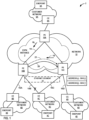
- FIG. 1 is a block diagram illustrating a network system 2 configured to provide fast reroute for traffic in EVPN-VXLAN, in accordance with one or more aspects of the techniques described in this disclosure.
- network system 2 includes customer networks 6A-6D ("customer networks 6") connected to an intermediate network 12.
- Intermediate network 12 may represent a public network that is owned and operated by a service provider to interconnect a plurality of edge networks, such as customer networks 6.
- Intermediate network 12 is a layer 3 (“L3”) network in the sense that it natively supports L3 operations as described in the OSI model. Common L3 operations include those performed in accordance with L3 protocols, such as the Internet protocol ("IP").
- IP Internet protocol
- Each of endpoints 4 may represent one or more non-edge switches, routers, hubs, gateways, security devices such as firewalls, intrusion detection, and/or intrusion prevention devices, servers, computer terminals, laptops, tablets, printers, databases, wireless mobile devices such as cellular phones or personal digital assistants, wireless access points, bridges, cable modems, application accelerators, or other network devices.
- security devices such as firewalls, intrusion detection, and/or intrusion prevention devices
- servers computer terminals, laptops, tablets, printers, databases
- wireless mobile devices such as cellular phones or personal digital assistants, wireless access points, bridges, cable modems, application accelerators, or other network devices.
- network system 2 may include any number of customer networks. Nonetheless, for ease of description, only customer networks 6A-6D are illustrated in FIG. 1 .
- additional network devices are not shown for ease of explanation, it should be understood that network system 2 may comprise additional network and/or computing devices such as, for example, one or more additional switches, routers, hubs, gateways, security devices such as firewalls, intrusion detection, and/or intrusion prevention devices, servers, computer terminals, laptops, printers, databases, wireless mobile devices such as cellular phones or personal digital assistants, wireless access points, bridges, cable modems, application accelerators, or other network devices.
- additional network and/or computing devices such as, for example, one or more additional switches, routers, hubs, gateways, security devices such as firewalls, intrusion detection, and/or intrusion prevention devices, servers, computer terminals, laptops, printers, databases, wireless mobile devices such as cellular phones or personal digital assistants, wireless access points, bridges, cable modems, application accelerators, or other network devices.
- Intermediate network 12 may provide a number of residential and business services, including residential and business class data services (which are often referred to as "Internet services” in that these data services permit access to the collection of publicly accessible networks referred to as the Internet), residential and business class telephone and/or voice services, and residential and business class television services.
- residential and business class data services which are often referred to as "Internet services” in that these data services permit access to the collection of publicly accessible networks referred to as the Internet
- residential and business class telephone and/or voice services and residential and business class television services.
- One such business class data service offered by a service provider intermediate network 12 includes layer 2 ("L2") EVPN service.
- Intermediate network 12 represents an L2/L3 switch fabric for one or more customer networks that may implement an L2 EVPN service.
- PE device 10C sends the reroute tunnel endpoint address to a primary PE device, e.g., PE device 10B (404).
- PE device 10C may advertise an Ethernet AD route including the reroute tunnel endpoint address.
- PE device 10C may advertise the reroute tunnel endpoint address in a Tunnel Egress Endpoint sub-TLV of a BGP tunnel encapsulation attribute that is carried in an Ethernet AD route.
- PE device 10C may advertise the reroute tunnel endpoint address (e.g., an IPv4 or IPv6 address) in an extended community (e.g., BGP Transitive Extended Community (type 0x06)) of an EVPN AD route or EVPN MAC route (e.g., EVPN Type 2 route).
- an extended community e.g., BGP Transitive Extended Community (type 0x06)
- the techniques of this disclosure may be implemented in a wide variety of devices or apparatuses, including a network device, an integrated circuit (IC) or a set of ICs (i.e., a chip set). Any components, modules or units have been described provided to emphasize functional aspects and does not necessarily require realization by different hardware units. The techniques described herein may also be implemented in hardware or any combination of hardware and software and/or firmware. Any features described as modules, units or components may be implemented together in an integrated logic device or separately as discrete but interoperable logic devices. In some cases, various features may be implemented as an integrated circuit device, such as an integrated circuit chip or chipset.
Landscapes
- Engineering & Computer Science (AREA)
- Computer Networks & Wireless Communication (AREA)
- Signal Processing (AREA)
- Computer Security & Cryptography (AREA)
- Data Exchanges In Wide-Area Networks (AREA)
Abstract
Description
- The disclosure relates to computer networks and, more particularly, to forwarding traffic within computer networks.
- A computer network is a collection of interconnected computing devices that can exchange data and share resources. Example network devices include switches or other layer two ("L2") devices that operate within the second layer of the Open Systems Interconnection ("OSI") reference model, i.e., the data link layer, and routers or other layer three ("L3") devices that operate within the third layer of the OSI reference model, i.e., the network layer. Network devices within computer networks often include a control unit that provides control plane functionality for the network device and forwarding units for routing or switching data units.
- An Ethernet Virtual Private Network ("EVPN") may be used to extend two or more remote L2 customer networks through an intermediate L3 network (usually referred to as a "provider network" or "core network"), in a transparent manner, i.e., as if the intermediate L3 network does not exist. In particular, the EVPN transports L2 communications, such as Ethernet packets or "frames," between customer networks connected by an IP infrastructure in which case IP/GRE tunneling or other IP tunneling can be used within the provider network to carry encapsulated L2 communications as if these customer networks were directly attached to the same local area network ("LAN").
- In an EVPN configuration, a customer edge ("CE") device of a customer network is said to be multi-homed when it is coupled to two or more physically different provider edge ("PE") devices on the same EVPN instance when the PE devices are resident on the same physical Ethernet segment. The PE devices on the Ethernet segment provide transport services through the intermediate network to a remote PE device, and each of the PE devices on the Ethernet segment may forward Ethernet frames in the Ethernet segment for the CE device. When a CE device is multi-homed to two or more PE devices, either one or all of the multi-homed PE devices are used to reach the customer network depending on the multi-homing mode of operation.
- An example of an IP tunneling scheme is Virtual eXtenstible Local Area Network ("VXLAN"). VXLAN provides a tunneling scheme to overlay L2 networks on top of L3 networks. VXLANs establish tunnels for communicating traffic over common physical IP infrastructure between the PE devices. That is, VXLAN overlay networks are designated for each customer network and operated over the existing LAN infrastructure of a data center, for example. Devices that support VXLANs are called virtual tunnel endpoints (VTEPs) (also known as "VXLAN tunnel endpoints"). VTEPs can be end hosts or network switches or routers. VTEPs encapsulate VXLAN traffic and de-encapsulate that traffic when it leaves the VXLAN tunnel. An EVPN implementing VXLAN is referred to herein as "EVPN-VXLAN."
- Particular aspects are set out in the appended independent claims. Various optional embodiments are set out in the dependent claims. In general, techniques are described for facilitating fast reroute for traffic in EVPN-VXLAN. For example, network devices, e.g., PE devices, may use fast reroute to restore traffic flow in response to a node or link failure. Typically, a PE device may implement fast reroute by pre-installing in its data plane a backup path that leads to a backup network device for handling traffic. However, a first PE device ("primary PE device") of an Ethernet segment may be inhibited from establishing a backup path over the core network to a second PE device (e.g., "backup PE device") of the Ethernet segment due to an EVPN "split-horizon filtering" rule. For example, the split-horizon filtering rule prevents a network device from forwarding traffic that is received from a tunnel (e.g., VXLAN tunnel) of a given split-horizon group over the core network from being forwarded back into the core network on another tunnel belonging to the same split-horizon group.
- In accordance with the techniques described in this disclosure, the backup PE device is configured with an additional tunnel endpoint address (referred to herein as "reroute tunnel endpoint address") for the backup path that is associated with a split-horizon group (referred to herein as "second split-horizon group") that is different than a tunnel endpoint address and first split-horizon group for another path used for normal traffic forwarding. The backup PE device sends the reroute tunnel endpoint address to the primary PE device. For example, the backup PE device may advertise an EVPN route including the reroute tunnel endpoint address, such as including the reroute tunnel endpoint address in an Egress Endpoint sub-type-length-value (sub-TLV) of a BGP tunnel encapsulation attribute carried in an Ethernet Auto-Discovery route (e.g., EVPN
Type 1 route), and/or including the reroute tunnel endpoint address in an extended community (e.g., BGP transitive extended community) of an Ethernet AD route or MAC/IP Advertisement route (e.g., EVPNType 2 route). - In response to receiving the reroute tunnel endpoint address, the primary PE device may use the reroute tunnel endpoint address to configure a backup path to the backup PE device over the core network. For example, a routing component of the primary PE device may configure a forwarding component of the primary PE device by installing the reroute tunnel endpoint address within the forwarding plane and one or more operations to cause the forwarding component to encapsulate a VXLAN header including the reroute tunnel endpoint address to a packet received from the core network when rerouting the packet back into the core network along the backup path to the backup PE device. In this way, when the primary PE device receives a packet over the core network and the access link from the primary PE device to the local CE device has failed, the primary PE device may reroute the packet back into the core network to the backup PE device, which in turn may forward the packet on the Ethernet segment to the local CE device.
- The techniques may provide one or more technical advantages. For example, by configuring a backup PE device of the Ethernet segment with a reroute tunnel endpoint address associated with a second split-horizon group that is different than a tunnel endpoint address associated with a first split-horizon group for another path used for normal traffic forwarding and sending the reroute tunnel endpoint address to the primary PE device, the primary PE device may install a backup path using the reroute tunnel endpoint address to reroute packets to the backup PE device without being inhibited by the split-horizon filtering rule. In this way, the PE devices may provide fast reroute for traffic in EVPN-VXLAN, and thus provide faster convergence (e.g., sub-second convergence) in the event an egress access link failure occurs.
- In one example, a method includes receiving, by a first provider edge (PE) device of an Ethernet segment and from a second PE device of the Ethernet segment that provides a customer edge (CE) device multi-homed to the first PE device and the second PE device with reachability to an Ethernet Virtual Private Network (EVPN) instance, a reroute tunnel endpoint address of the second PE device for a backup path to the second PE device, wherein the reroute tunnel endpoint address of the second PE device is associated with a second split-horizon group that is different than a tunnel endpoint address and a first split-horizon group of the second PE device for another path to the second PE device. The method also includes configuring, by a routing component of the first PE device and within a forwarding component of the first PE device, a backup path to the second PE device over a core network, wherein configuring the backup path comprises installing the reroute tunnel endpoint address within the forwarding component and one or more operations causing the forwarding component to encapsulate, to a packet received from the core network, a Virtualized eXtensible Local Area Network (VXLAN) header including the reroute tunnel endpoint address as a destination tunnel endpoint address of the VXLAN header. The method further includes receiving, by the forwarding component of first PE device, a packet from the core network. Moreover, the method includes rerouting, by the forwarding component of the first PE device and when an access link from the first PE device to the CE device has failed, the packet on the backup path by encapsulating the VXLAN header including the reroute tunnel endpoint address and forwarding the packet including the reroute tunnel endpoint address on the backup path to the second PE device over the core network.
- In another example, a method includes configuring a first provider edge (PE) device of an Ethernet segment with a reroute tunnel endpoint for a backup path to the first PE device, wherein the Ethernet segment provides a customer edge (CE) device that is multi-homed to the first PE device and a second PE device with reachability to an Ethernet Virtual Private Network (EVPN) instance, and wherein the reroute tunnel endpoint address of the first PE device is associated with a second split-horizon group that is different than a tunnel endpoint address and a first split-horizon group of the first PE device for another path to the first PE device. The method also includes sending, by the first PE device, the reroute tunnel endpoint address to a second PE device. The method also includes receiving, by the first PE device, a packet encapsulated with a Virtualized eXtensible Local Area Network (VXLAN) header including the reroute tunnel endpoint address as a destination tunnel endpoint address of the VXLAN header. The method further includes sending, by the first PE device, the packet on the Ethernet segment to the CE device.
- In yet another example, a first provider edge (PE) device of an Ethernet segment, comprises: a forwarding component; and a routing component configured to: receive, from a second PE device of the Ethernet segment, a reroute tunnel endpoint address of the second PE device for a backup path to the second PE device, wherein the Ethernet segment provides a customer edge (CE) device that is multi-homed to the first PE device and the second PE device with reachability to an Ethernet Virtual Private Network (EVPN) instance, and wherein the reroute tunnel endpoint address of the second PE device is associated with a second split-horizon group that is different than a tunnel endpoint address and a first split-horizon group of the second PE device for another path to the second PE device; and configure, within a forwarding component of the first PE device, a backup path to the second PE device over a core network, wherein configuring the backup path comprises installing the reroute tunnel endpoint address within the forwarding component and one or more operations causing the forwarding component to encapsulate, to a packet received from the core network, a Virtualized eXtensible Local Area Network (VXLAN) header including the reroute tunnel endpoint address as a destination tunnel endpoint address of the VXLAN header; and wherein, in response to the configuration of the backup path, the forwarding component is configured to: receive a packet from the core network; and reroute, when an access link from the first PE device to the CE device has failed, the packet on the backup path by encapsulating the VXLAN header including the reroute tunnel endpoint address and forwarding the packet including the reroute tunnel endpoint address on the backup path to the second PE device over the core network.
- The details of one or more aspects of the techniques are set forth in the accompanying drawings and the description below. Other features, objects, and advantages of the techniques of this disclosure will be apparent from the description and drawings, and from the claims.
-
-
FIG. 1 is a block diagram illustrating a network system configured to provide fast reroute for traffic in EVPN-VXLAN, in accordance with one or more aspects of the techniques described in this disclosure. -
FIG. 2 is a block diagram illustrating an example of a provider edge device configured to provide fast reroute for traffic in EVPN-VXLAN, in accordance to one or more aspects of the techniques described in this disclosure. -
FIGS. 3A-3C are block diagrams illustrating example packet fields of a route including the reroute tunnel endpoint address, in accordance with one or more aspects of the techniques described in this disclosure. -
FIG. 4 is a flowchart illustrating an example operation of PE devices configured to provide fast reroute for traffic in EVPN-VXLAN, in accordance with one or more aspects of the techniques described in this disclosure. - Like reference characters denote like elements throughout the figures and text.
-
FIG. 1 is a block diagram illustrating anetwork system 2 configured to provide fast reroute for traffic in EVPN-VXLAN, in accordance with one or more aspects of the techniques described in this disclosure. As shown inFIG. 1 ,network system 2 includescustomer networks 6A-6D ("customer networks 6") connected to anintermediate network 12.Intermediate network 12 may represent a public network that is owned and operated by a service provider to interconnect a plurality of edge networks, such ascustomer networks 6.Intermediate network 12 is a layer 3 ("L3") network in the sense that it natively supports L3 operations as described in the OSI model. Common L3 operations include those performed in accordance with L3 protocols, such as the Internet protocol ("IP"). L3 is also known as a "network layer" in the OSI model and the "IP layer" in the TCP/IP model, and the term L3 may be used interchangeably with "network layer" and "IP" throughout this disclosure. As a result,intermediate network 12 may be referred to herein as a Service Provider ("SP") network or, alternatively, as a "core network" considering thatnetwork 12 acts as a core to interconnect edge networks, such ascustomer networks 6. - In the example of
FIG. 1 , provideredge network devices 10A-10C (collectively, "PE devices 10") providecustomer endpoints 4A-4D (collectively, "endpoints 4") associated withcustomer networks 6 with access tointermediate network 12 via customer edge network devices, e.g., customeredge network devices 8A-8D (collectively, "CE devices 8"). PE devices 10 andCE devices 8 may each represent a router, switch, or other suitable network device that participates in an L2 virtual private network ("L2VPN") service, such as an EVPN. Each ofendpoints 4 may represent one or more non-edge switches, routers, hubs, gateways, security devices such as firewalls, intrusion detection, and/or intrusion prevention devices, servers, computer terminals, laptops, tablets, printers, databases, wireless mobile devices such as cellular phones or personal digital assistants, wireless access points, bridges, cable modems, application accelerators, or other network devices. - The configuration of
network system 2 illustrated inFIG. 1 is merely an example. For example, a network system may include any number of customer networks. Nonetheless, for ease of description,only customer networks 6A-6D are illustrated inFIG. 1 . Although additional network devices are not shown for ease of explanation, it should be understood thatnetwork system 2 may comprise additional network and/or computing devices such as, for example, one or more additional switches, routers, hubs, gateways, security devices such as firewalls, intrusion detection, and/or intrusion prevention devices, servers, computer terminals, laptops, printers, databases, wireless mobile devices such as cellular phones or personal digital assistants, wireless access points, bridges, cable modems, application accelerators, or other network devices. -
Intermediate network 12 may provide a number of residential and business services, including residential and business class data services (which are often referred to as "Internet services" in that these data services permit access to the collection of publicly accessible networks referred to as the Internet), residential and business class telephone and/or voice services, and residential and business class television services. One such business class data service offered by a service providerintermediate network 12 includes layer 2 ("L2") EVPN service.Intermediate network 12 represents an L2/L3 switch fabric for one or more customer networks that may implement an L2 EVPN service. An EVPN is a service that provides a form of L2 connectivity across an intermediate L3 network, such asintermediate network 12, to interconnect two or more L2 customer networks, such asL2 customer networks 6, that may be located in different geographical areas (in the case of service provider network implementation) and/or in different racks (in the case of a data center implementation). In some examples, the EVPN transports L2 communications, such as Ethernet packets or "frames," between customer networks connected by an IP infrastructure in which case IP/GRE tunneling or other IP tunneling can be used within the provider network to carry encapsulated L2 communications as if these customer networks were directly attached to the same local area network ("LAN"). Often, EVPN is transparent to the customer networks in that these customer networks are not aware of the intervening intermediate network and instead act and operate as if these customer networks were directly connected and form a single L2 network, and for this reason, EVPN may also be referred to as a "transparent LAN service. - To configure an EVPN, a network operator of
intermediate network 12 configures, via configuration or management interfaces, various devices, e.g., PE devices 10, included withinintermediate network 12 that interface withL2 customer networks 6. The EVPN configuration may include an EVPN instance ("EVI") 3, which comprises of one or more broadcast domains.EVPN instance 3 is configured withinintermediate network 12 forcustomer networks 6 to enableendpoints 4 withincustomer networks 6 to communicate with one another via the EVI as ifendpoints 4 were directly connected via an L2 network. Generally,EVI 3 may be associated with a virtual routing and forwarding instance ("VRF") on a PE device, such as any ofPE devices 10A-10C. Consequently, multiple EVIs (not shown) may be configured onPE devices 10A-10C for an Ethernet segment, e.g.,Ethernet segment 14, each of the EVIs providing a separate, logical L2 forwarding domain. As used herein, an EVI is an EVPN routing and forwarding instance spanningPE devices 10A-10C participating in the EVI. In the example ofFIG. 1 , each of PE devices 10 is configured withEVI 3 and exchanges EVPN routes to implementEVI 3, as further described below. - Each of PE devices 10 uses MAC routes specifying the MAC addresses learned by other PE devices to determine how to forward L2 communications to MAC addresses that belong to devices connected to other PE devices, i.e., to
remote CE devices 8 and/or devices behind CE devices operatively coupled to PE devices (e.g., endpoints 4). That is, each of PE devices 10 determine whether Ethernet frames can be sent directly to a particular one of the other CE devices, PE devices 10 or whether to treat the Ethernet frames as so called broadcast, unknown unicast, or multicast ("BUM") traffic that is to be flooded within the EVPN based on the MAC addresses learning information received from the other PE devices 10. - An example of an IP tunneling scheme is Virtual eXtensible Local Area Network ("VXLAN"). VXLANs provide an IP tunneling scheme to overlay L2 networks, e.g.,
customer networks 6, on top of L3 networks, e.g.,intermediate network 12. VXLANs establish tunnels for communicating traffic over common physical IP infrastructure between Network Virtualization Edges / VXLAN Tunneling Endpoints (VTEPs), e.g., PE devices 10. That is, VXLAN creates virtual L2 networks spanning physical L3 networks between VTEPs. For example, PE devices 10 operating as VTEPs may encapsulate VXLAN traffic and de-encapsulate that traffic when it leaves the VXLAN tunnel. As one example, VTEPs communicate traffic with a 24-bit segment ID, Virtual Network Identifier (VNI), that uniquely identifies the VXLAN. For instance, the VNI maps to a tenant Virtual Local Area Network (VLAN) identifier, where the tenant VLAN identifier gets mapped to an EVPN instance (EVI). To tunnel traffic, an ingress PE device may encapsulate an "outer packet" (referred to as "VXLAN header") with the VNI that identifies a corresponding VXLAN instance to tunnel the payload or "inner packet" over the EVPN. When an egress PE device receives the packet, the egress PE device de-encapsulates the VXLAN header and forwards the L2 communications to its local customer network. In a way, VXLAN "stretches" an L2 network over an intermediate L3 network. Additional examples of VXLAN are described in "Virtual eXtensible Local Area Network (VXLAN): A Framework forOverlaying Virtualized Layer 2 Networks overLayer 3 Networks," Request for Comments 7438, August 2014, the entire contents of which is incorporated by reference herein. PE devices 10 may implement other tunneling protocols, such as Network Virtualization using Generic Routing Encapsulation (NVGRE), Generic Routing Encapsulation (GRE), MPLS-over-GRE, User Datagram Protocol (UDP), or MPLS-over-UDP. - In the example of
FIG. 1 ,PE device 10A may receive L2 traffic originating fromcustomer network 6A and destined forcustomer network 6C, and encapsulate the L2 traffic fromcustomer network 6A with a VXLAN header that identifies a corresponding VXLAN instance, e.g.,VXLAN tunnel 19, and a destination VTEP, e.g.,PE device 10B, to tunnel the traffic toPE device 10B, which in turn forwards the traffic tocustomer network 6C. Similarly,PE device 10B may receive L2 traffic originating fromcustomer network 6B and destined forcustomer network 6D, and encapsulate the L2 traffic fromcustomer network 6B with a VXLAN header that identifies a corresponding VXLAN instance, e.g.,VXLAN tunnel 20, and a destination VTEP, e.g.,PE device 10C, to tunnel the traffic toPE device 10C, which in turn forwards the traffic tocustomer network 6D. - In an EVPN configuration, a CE device is said to be multi-homed when it is coupled to two or more physically different PE devices on the same EVI when the PE devices are resident on the same physical Ethernet segment. For example,
CE device 8C is coupled toPE devices 10B-10C vialinks 15B-15C, respectively, wherePE devices 10B-10C are capable of providingL2 customer network 6C with redundant connectivity to EVPN viaCE device 8C. Multi-homed devices are often employed by network operators so as to improve access to the EVPN provided byintermediate network 12 should a failure in one ofegress PE devices 10B-10C or one oflinks 15B-15C occur. When a CE device is multi-homed to two or more PE devices, either one or all of the multi-homed PE devices are used to reach the customer network depending on the multi-homing mode of operation. In this example,PE devices FIG. 1 ,CE devices CE device 8B is coupled toPE device 10B vialink 15A andCE device 8D is coupled to PE device 10D vialink 15D. - For each EVI, the EVPN protocol directs the PE devices to output a routing protocol message advertising an Ethernet Auto-Discovery (AD) route (e.g.,
EVPN Type 1 route) specifying the relevant Ethernet segment identifier (ESI) for the Ethernet segment coupled to the EVPN instance. That is, each of PE devices 10 may advertise an Ethernet AD route per Ethernet segment to advertise reachability of the Ethernet segment on the PE device. For example, each of PE devices 10 for each EVI may use a Border Gateway Protocol (BGP) to advertise an Ethernet AD route that includes an RD (which may include, e.g., an IP address of the originating PE device), ESI, Ethernet Tag Identifier, and MPLS label that identifies the Ethernet segment ("ESI label"). Each of the routes are advertised and imported by all multi-homed and remote PE devices that share the same EVI on the advertising ESI. In the example ofFIG. 1 , each ofPE devices 10B-10D ofEVI 3 advertise and import the routes described above to discover each other and to elect a designated forwarder forEthernet segment 14. - In some examples, Ethernet Tags are used to identify a particular broadcast domain, e.g., a VLAN, in an EVI. A PE device may advertise a unique EVPN label per <Ethernet Segment Identifier (ESI), Ethernet Tag> combination. This label assignment methodology is referred to as a per <ESI, Ethernet Tag> label assignment. Alternatively, a PE device may advertise a unique EVPN label per media access control (MAC) address. In still another example, a PE device may advertise the same single EVPN label for all MAC addresses in a given EVI. This label assignment methodology is referred to as a per EVI label assignment.
- Once the EVPN is operational for the {EVI, ESI} pair, PE devices 10 output a MAC/IP Advertisement route (e.g.,
EVPN Type 2 route) to other PE devices to announce media access control (MAC) addresses associated with customer equipment in their local customer network. For example, PE devices 10 output MAC/IP Advertisement routes including an RD, ESI, Ethernet Tag Identifier, MAC address and MAC address length, IP network address and IP network address length, and MPLS label, for example. As one example,PE devices 10B and 10D each advertises a MAC/IP Advertisement route to other PE devices to announce the MAC address ofCE device 8C and/orendpoint 4C incustomer network 6C that is reachable byEthernet segment 14. Additional information with respect to the EVPN protocol is described in "BGP MPLS-Based Ethernet VPN," Internet Engineering Task Force (IETF), RFC 7432, February 2015, the entire content of which is incorporated herein by reference. - In some examples, a PE device may use fast reroute (FRR) to reroute traffic in response to a link or node failure. To generally perform fast reroute, a primary PE device of an Ethernet segment pre-installs a backup path to reroute traffic to a backup PE device of the Ethernet segment and uses the backup path in the event of a link or node failure. Without the techniques described in this disclosure, a primary PE device is unable to establish a backup path, e.g., VXLAN tunnel, to a backup PE device of the Ethernet segment due to a "split-horizon filtering" rule. For example, the split-horizon filtering rule prevents traffic from being forwarded back to the source (e.g., receiving a packet from the core network and sending the packet back into the core network). To achieve split-horizon filtering, VXLAN tunnels are typically associated with the same split-horizon group. For example, as
VXLAN tunnel 19 andVXLAN tunnel 20 are added to a bridge domain, the VXLAN tunnels are typically configured with the same split-horizon group. Traffic that is received from a tunnel of a given split-horizon group is not forwarded to another tunnel of the same split-horizon group. In this example, becauseVXLAN tunnels PE device 10B is unable to send traffic that it receives fromintermediate network 12 viaVXLAN tunnel 19 back intointermediate network 12 tobackup PE device 10C viaVXLAN tunnel 20. - In accordance with the techniques described in this disclosure, PE devices of the Ethernet segment may provide fast reroute for traffic in EVPN-VXLAN. In this example, the backup PE device (e.g.,
PE device 10C) and primary PE device (e.g.,PE device 10B) may operate in an all-active EVPN multihoming mode.PE device 10C (the backup PE device for Ethernet segment 14), is configured with an additional tunnel endpoint address (referred to herein as "reroute tunnel endpoint address") for a backup path, where the reroute tunnel endpoint address is different than a tunnel endpoint address for another path toPE device 10C used for "normal traffic forwarding," e.g., for traffic forwarded onVXLAN tunnel 20. For example, to send traffic fromCE device 8B toCE device 8D,PE device 10B may useVXLAN tunnel 20 to tunnel traffic received fromCE device 8B toPE device 10C. In this example,PE device 10C is configured with a tunnel endpoint address "A" forVXLAN tunnel 20 associated with a first split-horizon group "X" for forwarding traffic on VXLAN tunnel 20 (illustrated inFIG. 1 as "ADDRESS A: SHG X"). Other paths, e.g.,VXLAN tunnel 19, are also associated with the first split-horizon group "X" such that the split-horizon filtering rule is applied. In this example,PE device 10C is also configured with a reroute tunnel endpoint address "B" for VXLAN tunnel 21 (e.g., the backup path) associated with a second split-horizon group "Y" for forwarding traffic on the backup path (illustrated inFIG. 1 as "ADDRESS B : SHG Y"). The reroute tunnel endpoint address and second split-horizon group forVXLAN tunnel 21 are different than the tunnel endpoint address and first split-horizon group forVXLAN tunnel 20. -
PE device 10C may send the reroute tunnel endpoint address to the primary PE device, e.g.,PE device 10B. As one example,PE device 10C may advertise an Ethernet Auto-Discovery (AD) route including the reroute tunnel endpoint address (illustrated as "route 16" inFIG. 1 ). As further described below,PE device 10C may advertise the reroute tunnel endpoint address in a Tunnel Egress Endpoint sub-type-length-value (sub-TLV) of a BGP tunnel encapsulation attribute that is carried in an Ethernet AD route, for example. Additional examples of the Tunnel Egress Endpoint sub-TLV is described in K. Patel, et al., "The BGP Tunnel Encapsulation Attribute," Internet-Draft, draft-ietf-idr-tunnel-encaps-22, January 7, 2021, the entire contents of which is incorporated by reference herein.Route 16 may set the ESI value to zero and include a route target of theEVI 3 for Ethernet segment 14 (and other route targets of other EVPN instances for Ethernet segment 14). As another example,PE device 10C may advertise the reroute tunnel endpoint address (e.g., an IPv4 or IPv6 address) in an extended community (e.g., BGP Transitive Extended Community (type 0x06)) for an Ethernet AD route (e.g.,EVPN Type 1 route) or MAC/IP advertisement route (e.g.,EVPN Type 2 route), as further described below. - In response to receiving the reroute tunnel endpoint address from
PE device 10C,PE device 10B, e.g., the primary PE device, may use the reroute tunnel endpoint address to configure the backup path (e.g., VXLAN tunnel 21) over the core network toPE device 10C. For example, a routing component ofPE device 10B may configure its forwarding component by installing, within the forwarding plane, the reroute tunnel endpoint address and configure one or more operations to cause the forwarding component to add the reroute tunnel endpoint address to a packet received from the core network and destined forCE device 8C when rerouting the packet back into the core network along the backup path (e.g., VXLAN tunnel 21) toPE device 10C. For example, the one or more operations may cause the forwarding component to encapsulate a VXLAN header including the reroute tunnel endpoint address as a destination VTEP of the VXLAN header to tunnel the packet toPE device 10C viaVXLAN tunnel 21. - In some examples,
PE device 10B may implement a Bidirectional Forwarding Detection (BFD) protocol to detect whether access link 15B has failed. Examples of BFD may include session-BFD (S-BFD) or Multihop-BFD (MH-BFD).PE device 10B may determine thataccess link 15B has failed based on determining that BFD messages have not been received fromCE device 8C in a configured time period, for example.PE device 10B may also detect whether an Ethernet interface or aggregate Ethernet interface has failed using an Ethernet failure detection mechanism (e.g., link fault signaling (LFS)) at the physical layer without using BFD. - If there is no link failure (e.g.,
access link 15B is operating normally),PE device 10B forwards the traffic that it receives fromintermediate network 12 onEthernet segment 14 toCE device 8C using a primary path (e.g., a primary next hop). For example,PE device 10B may have a primary path configured with a next hop toCE device 8C via an interface to accesslink 15B. - In response to determining that
access link 15B (or an Ethernet interface or aggregate Ethernet interface) has failed,PE device 10B may configure its forwarding component to use the backup path to reroute traffic onVXLAN tunnel 21. In this way, whenPE device 10B receivespacket 18 fromintermediate network 12 viaVXLAN tunnel 19 associated with the first split-horizon group "X", the forwarding component ofPE device 10B may automatically perform operations to encapsulate a VXLAN header with the reroute tunnel endpoint associated with the second split-horizon group "Y" as a destination VTEP address of the VXLAN header, and send the packet including the reroute tunnel endpoint address toPE device 10C overintermediate network 12 viaVXLAN tunnel 21. Because the tunnel endpoint address forVXLAN tunnel 21 is configured with a different split-horizon group than the tunnel endpoint address forVXLAN tunnel 19, the split-horizon filtering rule does not preventPE device 10B from forwarding the packet over the core network toPE device 10C viaVXLAN tunnel 21.PE device 10C receives the packet, and becausePE device 10C is the tunnel endpoint forVXLAN tunnel 21, de-encapsulates the VXLAN header from the packet and forwards the payload onEthernet segment 14 toCE device 8C. - For ease of illustration, the example of
FIG. 1 is described with respect to configuring a single reroute tunnel endpoint address for a single backup path (e.g., VXLAN tunnel 21). The techniques may also include configuring an additional reroute tunnel endpoint address for each of a plurality of backup paths. For example,PE device 10A may load balance the traffic that is to be delivered tocustomer network 6C acrossPE devices PE device 10C is the primary PE device andPE device 10B is the backup PE device,PE device 10B is configured with an additional tunnel endpoint address (e.g., reroute tunnel endpoint address) for a backup path fromPE device 10C toPE device 10B (not shown inFIG. 1 ), where the reroute tunnel endpoint address forPE device 10B is different than a tunnel endpoint address used for forwarding traffic on a primary path.PE device 10B may send the tunnel endpoint addresses toPE device 10C such thatPE device 10C, e.g., the primary PE device in this example, may use the reroute tunnel endpoint address associated withPE device 10B to configure the backup path over the core network toPE device 10B. -
FIG. 2 is a block diagram illustrating an example of a provider edge device configured to provide fast reroute for EVPN-VXLAN, in accordance to one or more aspects of the techniques described is this disclosure.PE device 200 is described with respect toPE devices FIG. 1 , but may be performed by any PE device. - As shown in
FIG. 2 ,PE device 200 includes acontrol unit 202 having a routing component 204 (control plane), andcontrol unit 202 that is coupled to forwarding component 230 (data plane).Forwarding component 230 is associated with one or more interface cards 240A-240N ("IFCs 240") that receive packets viainbound links 242A-242N ("inbound links 242") and send packets viaoutbound links 244A-244N ("outbound links 244").IFCs 240 are typically coupled to links 242, 244 via a number of interface ports (not shown). Inbound links 242 and outbound links 244 may represent physical interfaces, logical interfaces, or some combination thereof. - Elements of
control unit 202 andforwarding component 230 may be implemented solely in software, or hardware, or may be implemented as combinations of software, hardware, or firmware. For example,control unit 202 may include one ormore processors 206 that may represent, one or more microprocessors, digital signal processors ("DSPs"), application specific integrated circuits ("ASICs"), field programmable gate arrays ("FPGAs"), or any other equivalent integrated or discrete logic circuitry, or any combination thereof, which execute software instructions. In that case, the various software modules ofcontrol unit 202 may comprise executable instructions stored, embodied, or encoded in a computer-readable medium, such as a computer-readable medium, containing instructions. Instructions embedded or encoded in a computer-readable medium may cause a programmable processor, or other processor, to perform the method, e.g., when the instructions are executed. Computer-readable media may include random access memory ("RAM"), read only memory ("ROM"), programmable read only memory (PROM), erasable programmable read only memory ("EPROM"), electronically erasable programmable read only memory ("EEPROM"), non-volatile random access memory ("NVRAM"), flash memory, a hard disk, a CD-ROM, a floppy disk, a cassette, a solid state drive, magnetic media, optical media, or other computer-readable media. Computer-readable media may be encoded with instructions corresponding to various aspects ofPE device 200, e.g., protocols, processes, and modules.Control unit 202, in some examples, retrieves and executes the instructions from memory (not shown) for these aspects. -
Routing component 204 operates as a control plane forPE device 200 and includes an operating system that provides a multi-tasking operating environment for execution of a number of concurrent processes.Routing component 204 includes akernel 210, which provides a run-time operating environment for user-level processes.Kernel 210 may represent, for example, a UNIX operating system derivative such as Linux or Berkeley Software Distribution ("BSD").Kernel 210 offers libraries and drivers by which user-level processes may interact with the underlying system.Hardware environment 208 ofrouting component 204 includesprocessor 206, described above, that executes program instructions loaded into a main memory (not shown inFIG. 2 ) from a storage device (also not shown inFIG. 2 ) in order to execute the software stack, including bothkernel 210 and processes executing on the operating environment provided bykernel 210. -
Kernel 210 provides an operating environment that executesvarious protocols 214 at different layers of a network stack, including protocols for implementing EVPN networks. For example,routing component 204 includes network protocols that operate at a network layer of the network stack.Protocols 214 provide control plane functions for storing network topology in the form of routing tables or other structures, executing routing protocols to communicate with peer routing devices and maintain and update the routing tables, and provide management interface(s) to allow user access and configuration ofPE device 200. That is,routing component 204 is responsible for the maintenance ofrouting information 218 to reflect the current topology of a network and other network entities to whichPE device 200 is connected. In particular, routing protocols are used to periodically updaterouting information 218 to reflect the current topology of the network and other entities based on routing protocol messages received byPE device 200. - In the example of
FIG. 2 ,protocols 214 include routing protocols, such as Border Gateway Protocol ("BGP") 216 for exchanging routing information with other routing devices and for updatingrouting information 218. In EVPN,PE device 200 may use BGP to advertise to other PE devices the MAC addressesPE device 200 has learned from local customer edge network devices to whichPE device 200 is connected. In particular,PE device 200 may use a BGP route advertisement message to announce reachability information for the EVPN, where the BGP route advertisement specifies one or more MAC addresses learned byPE device 200 instead of L3 routing information.PE device 200updates routing information 218 based on the BGP route advertisement message.Protocols 214 may also include failure detection protocols, such as Bidirectional Forwarding Detection ("BFD")protocol 217 for exchanging BFD messages to detect node failure. In some examples,BFD protocol 217 may include seamless-BFD (S-BFD) or multihop-BFD (MH-BFD). -
Protocols 214 may also include tunneling protocols, such as Virtual eXtensible LAN (VXLAN) 215, or other tunneling protocols not shown inFIG. 2 , such as NVGRE, GRE, UDP and/or MPLS tunneling protocols. - Routing
information 218 may include information defining a topology of a network, including one or more routing tables and/or link-state databases. Typically, the routing information defines routes (i.e., series of next hops) through a network to destinations / prefixes within the network learned via a distance-vector routing protocol (e.g., BGP) or defines the network topology with interconnected links learned using a link state routing protocol (e.g., IS-IS or OSPF). In contrast, forwardinginformation 232 is generated based on selection of certain routes within the network and maps packet key information (e.g., L2 / L3 source and destination addresses and other select information from a packet header) to one or more specific next hop forwarding structures within forwardinginformation 232 and ultimately to one or more specific output interface ports ofIFCs 240.Routing component 204 may generate forwardinginformation 232 in the form of a radix tree having leaf nodes that represent destinations within the network, a series of tables, a link list, a database, a flat file, or various other data structures. -
Routing component 204 also includes anEVPN module 220 that performs L2learning using BGP 216.EVPN module 220 may maintain tables for each EVI established byPE device 200, or in alternative examples may maintain one or more tables that are independent of each respective EVI.PE device 200 may useEVPN module 220 to advertise, e.g., EVPN routes including Ethernet AD routes (Type 1) to advertise reachability ofPE device 200 for an Ethernet segment and Ethernet segment routes (Type 4) to discover other PE devices of the Ethernet segment and for purposes of DF election (and backup DF election) for the Ethernet segment.PE device 200 may useEVPN module 220 to advertise other EVPN routes, such as inclusive multicast Ethernet Tag (IMET) routes (Type 3) to advertise information aboutPE device 200 that is used to send BUM traffic toPE device 200.EVPN module 220 may store information from the routes, such as the identification of PE devices of an Ethernet segment and additional information provided by attributes and/or extended communities of the EVPN routes. Information may include, for example, one or more reroute tunnel endpoint addresses for backup paths (e.g., VXLAN tunnels), as further described below. -
Routing component 204 includes aconfiguration interface 222 that receives and may report configuration data forPE device 200.Configuration interface 222 may represent a command line interface; a graphical user interface; Simple Network Management Protocol ("SNMP"), Netconf, or another configuration protocol; or some combination of the above in some examples.Configuration interface 222 receives configuration data configuring thePE device 200, and other constructs that at least partially define the operations forPE device 200, including the techniques described herein. For example, an administrator may, after powering-up, activating or otherwise enablingPE device 200 to operate within a network, interact withcontrol unit 202 viaconfiguration interface 222 to configurePE device 200 to perform the techniques described in this disclosure. -
Forwarding component 230 represents hardware and logic functions that provide high-speed forwarding of network traffic.Forwarding component 230 implements data plane (also known as a "forwarding plane") functionality to handle packet processing from ingress interfaces on which packets are received to egress interfaces to which packets are sent.Forwarding component 230 determines data packet forwarding throughPE device 200, applies services, rate limits packet flows, filters packets, and otherwise processes the packets using forwarding structures and lookup data installed by routingcomponent 204 to theforwarding component 230. -
Forwarding component 230 binds actions to be performed on packets received by the forwarding component to identification of one or more properties of the packets. That is, upon identifying certain packet properties, forwardingcomponent 230 performs the action abound to the properties. Packet properties may include packet metadata such as a particular packet's ingress interface or egress interface (as determined by the forwarding component) as well as information carried by the packet and packet header, such as packet header fields, destination route prefixes, layer four (L4) or Transport Layer protocol destination ports, and the packet payload. Actions bound to packet characteristics may include count, discard, forward to a specified next-hop or interface, filter, sample, rate limit, and Quality of Service (QoS) marking, differential services (DiffServ), load balance, intrusion detection and prevention, L2 class of service (CoS), and L2 or L2 Virtual Private Network (L2VPN) switching. -
Forwarding component 230 typically includes a set of one or more forwarding chips programmed with forwarding information (e.g., forwarding information 232) that maps network destinations with specific next hops and the corresponding output interface ports. For example, forwardingcomponent 230 may include one or more programmable application-specific integrated circuits (ASIC)-based packet processors (not shown) that process packets to identify packet properties and perform actions bound to the properties. The ASIC-based packet processors include key engines that execute microcode (or "microinstructions") to control and apply fixed hardware components of the ASICs to process packet "keys." A packet key includes packet fields and other parameters that determine a flow of packet processing for the packet along an internal forwarding path. A forwarding path comprises programmable, executable microcode and fixed hardware components that determine the packet processing actions and other operations performed by the key engines. The forwarding path may include, for example, executable instructions, programmable logic, and application-specific logic that perform lookups, rate limit packet flows, and manipulate packet keys, among other functions. - In general, when
PE device 200 receives a packet via one of inbound links 242, forwardingcomponent 230 identifies an associated next hop for the data packet by traversing the programmed forwarding information based on information within the packet, e.g., in the case of a packet with VXLAN encapsulation, the VXLAN header.Forwarding component 230 forwards the packet on one of outbound links 244 mapped to the corresponding next hop. -
Forwarding component 230stores forwarding information 232 for each Ethernet VPN Instance (EVI) established byPE device 200 to associate network destinations with specific next hops and the corresponding interface ports.Forwarding unit 230 forwards the data packet on one of outbound links 244 to the corresponding next hop in accordance with forwardinginformation 232 associated with an Ethernet segment. At this time,forwarding component 230 may encapsulate and/or de-encapsulate packet headers (or push and/or pop labels in the case of MPLS) from the packet to forward the packet to the next hop. For example, ifPE device 200 is to send a packet to a peer tunneling endpoint over the intermediate network, forwardingcomponent 230 may encapsulate an outer tunnel transport header, e.g., an outer Ethernet header, outer IP header, outer tunnel scheme header, outer VXLAN header, inner destination MAC address, and inner source MAC address. IfPE device 200 receives an encapsulated packet,forwarding component 230 may de-encapsulate the outer tunnel transport header and send the inner payload to the destination in accordance with forwardinginformation 232. Additional information regarding next hops is described in PLATFORM-INDEPENDENT CONTROL PLANE AND LOWER-LEVEL DERIVATION OF FORWARDING STRUCTURES,U.S. Patent No. 7,990,993, filed November 6, 2008 , and additional information regarding the configuration of forwarding paths within the forwarding component is described in PACKET FORWARDING PATH PROGRAMMING USING HIGH-LEVEL DESCRIPTION LANGUAGE,"U.S. Patent No. 8,806,058, filed July 29, 2011 , the entire contents of each of which is incorporated by reference herein. - In accordance with the techniques described herein,
routing component 204 may include a fast reroutemodule 224 that performs the techniques described in this disclosure. For example,PE device 200 may represent an example of a backup PE device (e.g.,PE device 10C ofFIG. 1 ). In this example, an administrator may configurePE device 200 viaconfiguration interface 222 with a reroute tunnel endpoint address associated with a second split-horizon group for the backup path, where the reroute tunnel endpoint address and second split-horizon group are different than a tunnel endpoint address and first split-horizon group for another path used for normal traffic forwarding (e.g.,VXLAN tunnel 20 ofFIG. 1 ). For example,PE device 200 may be configured with a tunnel endpoint address and a first split-horizon group for a VXLAN tunnel 20 (e.g., "Address A: SHG X") and a different tunnel endpoint address and second split-horizon group for backup path VXLAN tunnel 21 (e.g., "Address B : SHG Y"). -
PE device 200 may useBGP 216 to advertise an EVPN route including the reroute tunnel endpoint address. For example, fast reroutemodule 224 may causePE device 200 to include the reroute tunnel endpoint address in a Tunnel Egress Endpoint sub-TLV of a BGP Tunnel Encapsulation Attribute carried in an Ethernet AD route. As another example, fast reroutemodule 224 may causePE device 200 to include the reroute tunnel endpoint address within a BGP Transitive Extended Community (type 0x06) carried in an Ethernet AD route or an EVPN MAC/IP Advertisement route (e.g.,EVPN Type 2 route).PE device 200 may then advertise the EVPN route including the reroute tunnel endpoint address to the primary PE device. - In examples in which
PE device 200 represents a primary PE device (e.g.,PE device 10B ofFIG. 1 ),PE device 200 may receive the EVPN route including the reroute tunnel endpoint address associated with the backup PE device. In response, fast reroutemodule 224 ofPE device 200 may install the reroute tunnel endpoint address within forwarding information 232 (e.g., illustrated as "reroutetunnel endpoint address 234" inFIG. 2 ) and furtherconfigures forwarding component 230 with one or more operations to causeforwarding component 230 to encapsulate a VXLAN header to an incoming packet received from the core network, where the reroute tunnel endpoint address is set as a destination VTEP address of the VXLAN header to tunnel the packet to the backup PE device via the backup path (e.g., VXLAN tunnel 21). - In this way, when
PE device 200 receives, via one of inbound links 242 of a core-facing interface and an access link to a locally connected CE device is down, theforwarding component 230 may, according to the forwardinginformation 232, encapsulate the packet with the reroute tunnel endpoint address and send the packet including the reroute tunnel endpoint address to the backup PE device via a core-facing interface to the backup path. -
FIGS. 3A-3C are block diagrams illustrating example packet fields of a route including the reroute tunnel endpoint address, in accordance with one or more aspects of the techniques described in this disclosure. -
FIG. 3A is a block diagram illustrating an exampleEgress Endpoint sub-TLV 300 of a BGP Tunnel Encapsulation Attribute. A BGP Tunnel Encapsulation Attribute is a Type-Length-Value (TLV) that specifies the type of tunnel (e.g., type 0x06 for VXLAN), a length of the value field, and one or more attributes specified in sub-TLVs, such asEgress Endpoint sub-TLV 300. -
Egress Endpoint sub-TLV 300 is used to specify the address of the egress endpoint of the tunnel. For example,Egress Endpoint sub-TLV 300 includes areserved field 302, anaddress family field 304, and anaddress field 306. Theaddress family field 304 may specify a value from an "Address Family Numbers" registry of the Internet Assigned Numbers Authority (IANA). The value specified in theaddress family field 304 may indicate whether the address specified inaddress field 306 is an IPv4 or IPv6 address. - The
address field 306 may specify the reroute tunnel endpoint address, as described in this disclosure. The reroute tunnel endpoint address may be an IPv4 address or an IPv6 address. In some examples, reservedfield 302 may include a flags field with a bit to specify whether the reroute tunnel endpoint address is used when protecting egress link failures (e.g.,access link 15B failures) or other scenarios in which the primary PE device is unable to send traffic to the local CE device (e.g., when the MAC address of the primary PE device is being updated). Additional examples of the Tunnel Egress Endpoint sub-TLV field is described in Internet-Draft, draft-ietf-idr-tunnel-encaps-22, which is incorporated by reference above. -
FIG. 3B is a block diagram illustrating an example BGP transitiveextended community 320 that includes an IPv4 reroute tunnel endpoint address, in accordance with one or more aspects of the techniques described in this disclosure. In this example, BGP transitiveextended community 320 includes atype field 322, asub-type field 324, aflags field 326, anaddress length field 328, and a reroute tunnelendpoint address field 330. - The
type field 322 specifies the type as EVPN (e.g., type 0x06). Thesub-type field 324 may specify a value (e.g., a value registered with the IANA) associated with the reroute tunnel endpoint address to indicate the BGP transitiveextended community 320 includes a reroute tunnel endpoint address. The flags field 326 may specify whether the reroute tunnel endpoint address is used when protecting egress link failures (e.g.,access link 15B failures) or other scenarios in which the primary PE device is unable to send traffic to the local CE device (e.g., when the MAC address of the primary PE device is being updated). Theaddress length field 328 may specify the length of the reroute tunnel endpoint address. The reroute tunnelendpoint address field 330 may specify the reroute tunnel endpoint address, as described in this disclosure. In this example, the reroute tunnelendpoint address field 330 may include 4 or 16 octets to specify an IPv4 address of the reroute tunnel endpoint address. -
FIG. 3C is a block diagram illustrating an example BGP transitiveextended community 340 that includes an IPv6 reroute tunnel endpoint address, in accordance with one or more aspects of the techniques described in this disclosure. In this example, BGP transitiveextended community 340 includes atype field 342, asub-type field 344, aflags field 346, areserved field 348, and a reroute tunnelendpoint address field 350. - The
type field 342 specifies the type as EVPN (e.g., type 0x06). Thesub-type field 344 may specify a value (e.g., a value registered with the IANA) associated with the reroute tunnel endpoint address to indicate the BGP transitiveextended community 340 includes a reroute tunnel endpoint address. The flags field 346 may specify whether the reroute tunnel endpoint address is used when protecting egress link failures (e.g.,access link 15B failures) or other scenarios in which the primary PE device is unable to send traffic to the local CE device (e.g., when the MAC address of the primary PE device is being updated). The reroute tunnelendpoint address field 350 may specify the reroute tunnel endpoint address, as described in this disclosure. In this example, the reroute tunnelendpoint address field 350 may include 128-bits to specify an IPv6 address of the reroute tunnel endpoint address. Additional examples of BGP transitive extended communities is described in E. Rosen, et al., "IANA Registries for BGP Extended Communities," Request for Comments 7153, March 2014, the entire contents of which is incorporated by reference herein. -
FIG. 4 is a flowchart illustrating an example operation of PE devices, in accordance with one or more aspects of the techniques described in this disclosure.FIG. 4 will be described with respect PE devices 10 ofFIG. 1 andPE device 200 ofFIG. 2 . - In the example of
FIG. 4 ,PE device 10C ofEthernet segment 14 is configured with a reroute tunnel endpoint address associated with a second split-horizon group for a backup path, wherein the reroute tunnel endpoint address and second split-horizon group are different than the tunnel endpoint address and first split-horizon group of another path toPE device 10C used for normal traffic forwarding (402). -
PE device 10C sends the reroute tunnel endpoint address to a primary PE device, e.g.,PE device 10B (404). For example,PE device 10C may advertise an Ethernet AD route including the reroute tunnel endpoint address. As one example,PE device 10C may advertise the reroute tunnel endpoint address in a Tunnel Egress Endpoint sub-TLV of a BGP tunnel encapsulation attribute that is carried in an Ethernet AD route. As another example,PE device 10C may advertise the reroute tunnel endpoint address (e.g., an IPv4 or IPv6 address) in an extended community (e.g., BGP Transitive Extended Community (type 0x06)) of an EVPN AD route or EVPN MAC route (e.g.,EVPN Type 2 route). - The primary PE device, e.g.,
PE device 10B receives the reroute tunnel endpoint address fromPE device 10C (406) and may configure within its forwarding component 230 a backup path (e.g., backup next hop) to thebackup PE device 10C over the core network (408). For example, fast reroutemodule 224 of therouting component 204 ofPE device 10B may install the reroute tunnel endpoint address within theforwarding component 230 and one or more operations that causes theforwarding component 230 to encapsulate the packet with a VXLAN header with the reroute tunnel endpoint as a destination VTEP address of the VXLAN header to send the packet toPE device 10C overintermediate network 12 via the backup path, e.g.,VXLAN tunnel 21. -
PE device 10B may detect whether an access link to the CE device (e.g.,access link 15B toCE device 8C) has failed (410). For example,PE device 10B may implement BFD protocol 317 to detect whether the access link has failed. If the access link has not failed ("NO" of step 410),PE device 10B sends a packet received from the core network using the primary path, e.g., sending the packet onEthernet segment 14 toCE device 8C (412). If the access link has failed ("YES" of step 410),PE device 10B reroutes the packet received from the core network using the backup path, for example, by encapsulating the packet with a VXLAN header including the reroute tunnel endpoint as a destination VTEP address of the VXLAN header, and sends the packet including the reroute tunnel endpoint address on the backup path toPE device 10C over the core network (414). - When
PE device 10C receives the packet including the reroute tunnel endpoint address (416),PE device 10C de-encapsulates the VXLAN header (418) and forwards the packet onEthernet segment 14 toCE device 8C (420). - The techniques of this disclosure may be implemented in a wide variety of devices or apparatuses, including a network device, an integrated circuit (IC) or a set of ICs (i.e., a chip set). Any components, modules or units have been described provided to emphasize functional aspects and does not necessarily require realization by different hardware units. The techniques described herein may also be implemented in hardware or any combination of hardware and software and/or firmware. Any features described as modules, units or components may be implemented together in an integrated logic device or separately as discrete but interoperable logic devices. In some cases, various features may be implemented as an integrated circuit device, such as an integrated circuit chip or chipset.
- If implemented in software, the techniques may be realized at least in part by a computer-readable medium comprising instructions that, when executed in a processor, performs one or more of the methods described above. The computer-readable medium may be a physical structure, and may form part of a computer program product, which may include packaging materials. In this sense, the computer readable medium may be non-transitory. The computer-readable medium may comprise random access memory (RAM) such as synchronous dynamic random access memory (SDRAM), read-only memory (ROM), non-volatile random access memory (NVRAM), electrically erasable programmable read-only memory (EEPROM), FLASH memory, magnetic or optical data storage media, and the like. A computer readable medium may also or alternatively include transient media such as carrier signals and transmission media.
- The code or instructions may be executed by one or more processors, such as one or more digital signal processors (DSPs), general purpose microprocessors, an application specific integrated circuits (ASICs), field programmable logic arrays (FPGAs), or other equivalent integrated or discrete logic circuitry. Accordingly, the term "processor," as used herein may refer to any of the foregoing structure or any other structure suitable for implementation of the techniques described herein. In addition, in some aspects, the functionality described herein may be provided within dedicated software modules or hardware modules configured for encoding and decoding, or incorporated in a combined video codec. Also, the techniques could be fully implemented in one or more circuits or logic elements.
- Thus, from one perspective, there has now been described techniques for providing fast reroute for traffic in EVPN-VXLAN. For example, a backup PE device of an Ethernet segment is configured with an additional tunnel endpoint address ("reroute tunnel endpoint address") for a backup path associated with a second split-horizon group that is different than a tunnel endpoint address and first split-horizon group for another path used for normal traffic forwarding. The backup PE device sends the reroute tunnel endpoint address to a primary PE device of the Ethernet segment, which uses the reroute tunnel endpoint address to configure a backup path to the backup PE device over the core network. For example, the primary PE device may install the reroute tunnel endpoint address within its forwarding plane and one or more operations to cause the primary PE device to encapsulate a VXLAN header including the reroute tunnel endpoint address when rerouting the packet along the backup path.
- Further examples of feature combinations taught by the present disclosure are set out in the following numbered clauses.
- 1. A method comprising:
- receiving, by a first provider edge (PE) device of an Ethernet segment and from a second PE device of the Ethernet segment that provides a customer edge (CE) device multi-homed to the first PE device and the second PE device with reachability to an Ethernet Virtual Private Network (EVPN) instance, a reroute tunnel endpoint address of the second PE device for a backup path to the second PE device, wherein the reroute tunnel endpoint address of the second PE device is associated with a second split-horizon group that is different than a tunnel endpoint address and a first split-horizon group of the second PE device for another path to the second PE device;
- configuring, by a routing component of the first PE device and within a forwarding component of the first PE device, a backup path to the second PE device over a core network, wherein configuring the backup path comprises installing the reroute tunnel endpoint address within the forwarding component and one or more operations causing the forwarding component to encapsulate, to a packet received from the core network, a Virtualized eXtensible Local Area Network (VXLAN) header including the reroute tunnel endpoint address as a destination tunnel endpoint address of the VXLAN header;
- receiving, by the forwarding component of first PE device, a packet from the core network; and
- rerouting, by the forwarding component of the first PE device and when an access link from the first PE device to the CE device has failed, the packet on the backup path by encapsulating the VXLAN header including the reroute tunnel endpoint address and forwarding the packet including the reroute tunnel endpoint address on the backup path to the second PE device over the core network.
- 2. The method of
clause 1, wherein receiving the reroute tunnel endpoint address comprises receiving an Ethernet Auto-Discovery route including the reroute tunnel endpoint address. - 3. The method of any of
clauses - 4. The method of any of
clauses 1 to 3, wherein the reroute tunnel endpoint address is included in a Border Gateway Protocol (BGP) transitive extended community. - 5. The method of any of
clauses 1 to 4, wherein receiving the reroute tunnel endpoint address comprises receiving a MAC/IP Advertisement route including the reroute tunnel endpoint address. - 6. The method of any of
clauses 1 to 5, wherein the reroute tunnel endpoint address is included in a Border Gateway Protocol (BGP) transitive extended community. - 7. A method comprising:
- configuring a first provider edge (PE) device of an Ethernet segment with a reroute tunnel endpoint for a backup path to the first PE device, wherein the Ethernet segment provides a customer edge (CE) device that is multi-homed to the first PE device and a second PE device with reachability to an Ethernet Virtual Private Network (EVPN) instance, and wherein the reroute tunnel endpoint address of the first PE device is associated with a second split-horizon group that is different than a tunnel endpoint address and a first split-horizon group of the first PE device for another path to the first PE device;
- sending, by the first PE device, the reroute tunnel endpoint address to a second PE device;
- receiving, by the first PE device, a packet encapsulated with a Virtualized eXtensible Local Area Network (VXLAN) header including the reroute tunnel endpoint address as a destination tunnel endpoint address of the VXLAN header; and
- sending, by the first PE device, the packet on the Ethernet segment to the CE device.
- 8. The method of
clause 7, wherein sending the reroute tunnel endpoint address to the second PE device comprises sending an Ethernet Auto-Discovery route including the reroute tunnel endpoint address. - 9. The method of any of
clauses - 10. The method of any of
clauses 7 to 9, wherein the reroute tunnel endpoint address is included in a Border Gateway Protocol (BGP) transitive extended community. - 11. The method of any of
clauses 7 to 10, wherein sending the reroute tunnel endpoint address to the second PE device comprises sending a MAC/IP Advertisement route including the reroute tunnel endpoint address. - 12. The method of any of
clauses 7 to 11, wherein the reroute tunnel endpoint address is included in a Border Gateway Protocol (BGP) transitive extended community. - 13. A first provider edge (PE) device of an Ethernet segment, comprising:
- a forwarding component; and
- a routing component configured to:
- receive, from a second PE device of the Ethernet segment, a reroute tunnel endpoint address of the second PE device for a backup path to the second PE device, wherein the Ethernet segment provides a customer edge (CE) device that is multi-homed to the first PE device and the second PE device with reachability to an Ethernet Virtual Private Network (EVPN) instance, and wherein the reroute tunnel endpoint address of the second PE device is associated with a second split-horizon group that is different than a tunnel endpoint address and a first split-horizon group of the second PE device for another path to the second PE device; and
- configure, within a forwarding component of the first PE device, a backup path to the second PE device over a core network, wherein configuring the backup path comprises installing the reroute tunnel endpoint address within the forwarding component and one or more operations causing the forwarding component to encapsulate, to a packet received from the core network, a Virtualized eXtensible Local Area Network (VXLAN) header including the reroute tunnel endpoint address as a destination tunnel endpoint address of the VXLAN header; and
- wherein, in response to the configuration of the backup path, the forwarding component is configured to: receive a packet from the core network; and
reroute, when an access link from the first PE device to the CE device has failed, the packet on the backup path by encapsulating the VXLAN header including the reroute tunnel endpoint address and forwarding the packet including the reroute tunnel endpoint address on the backup path to the second PE device over the core network.
- 14. The first PE device of clause 13, wherein to receive the reroute tunnel endpoint address, the routing component is configured to receive an Ethernet Auto-Discovery route including the reroute tunnel endpoint address.
- 15. The first PE device of any of
clauses 13 or 14, wherein the reroute tunnel endpoint address is included in an Egress Endpoint sub-TLV of a Border Gateway Protocol (BGP) Tunnel Encapsulation Attribute carried in the Ethernet Auto-Discovery route. - 16. The first PE device of any of clauses 13 to 15, wherein the reroute tunnel endpoint address is included in a Border Gateway Protocol (BGP) transitive extended community.
- 17. The first PE device of any of clauses 13 to 16, wherein to receive the reroute tunnel endpoint address, the routing component is configured to receive a MAC/IP Advertisement route including the reroute tunnel endpoint address.
- 18. The first PE device of any of clauses 13 to 17, wherein the reroute tunnel endpoint address is included in a Border Gateway Protocol (BGP) transitive extended community.
- 19. The first PE device of any of clauses 13 to 18, wherein the routing component is further configured to:
- configure the first PE device with a reroute tunnel endpoint for a backup path to the first PE device, wherein the reroute tunnel endpoint address of the first PE device is associated with a second split-horizon group that is different than a tunnel endpoint address and a first split-horizon group of the first PE device for another path to the first PE device;
- send the reroute tunnel endpoint address to a second PE device;
- wherein, in response to the configuration of the backup path, the forwarding component is further configured to:
- receive a packet encapsulated with a VXLAN header including the reroute tunnel endpoint address for the backup path to the first PE device as a destination tunnel endpoint address of the VXLAN header; and
- send the packet on the Ethernet segment to the CE device.
-
- 1. A method comprising:
- receiving, by a first provider edge (PE) device of an Ethernet segment and from a second PE device of the Ethernet segment that provides a customer edge (CE) device multi-homed to the first PE device and the second PE device with reachability to an Ethernet Virtual Private Network (EVPN) instance, a reroute tunnel endpoint address of the second PE device for a backup path to the second PE device, wherein the reroute tunnel endpoint address of the second PE device is associated with a second split-horizon group that is different than a tunnel endpoint address and a first split-horizon group of the second PE device for another path to the second PE device;
- configuring, by a routing component of the first PE device and within a forwarding component of the first PE device, a backup path to the second PE device over a core network, wherein configuring the backup path comprises installing the reroute tunnel endpoint address within the forwarding component and one or more operations causing the forwarding component to encapsulate, to a packet received from the core network, a Virtualized eXtensible Local Area Network (VXLAN) header including the reroute tunnel endpoint address as a destination tunnel endpoint address of the VXLAN header;
- receiving, by the forwarding component of first PE device, a packet from the core network; and
- rerouting, by the forwarding component of the first PE device and when an access link from the first PE device to the CE device has failed, the packet on the backup path by encapsulating the VXLAN header including the reroute tunnel endpoint address and forwarding the packet including the reroute tunnel endpoint address on the backup path to the second PE device over the core network.
- 2. The method of example 1, wherein receiving the reroute tunnel endpoint address comprises receiving an Ethernet Auto-Discovery route including the reroute tunnel endpoint address.
- 3. The method of any of examples 1 or 2, wherein the reroute tunnel endpoint address is included in an Egress Endpoint sub-TLV of a Border Gateway Protocol (BGP) Tunnel Encapsulation Attribute carried in the Ethernet Auto-Discovery route.
- 4. The method of any of examples 1 to 3, wherein the reroute tunnel endpoint address is included in a Border Gateway Protocol (BGP) transitive extended community.
- 5. The method of any of examples 1 to 4, wherein receiving the reroute tunnel endpoint address comprises receiving a MAC/IP Advertisement route including the reroute tunnel endpoint address.
- 6. The method of any of examples 1 to 5, wherein the reroute tunnel endpoint address is included in a Border Gateway Protocol (BGP) transitive extended community.
- 7. A method comprising:
- configuring a first provider edge (PE) device of an Ethernet segment with a reroute tunnel endpoint for a backup path to the first PE device, wherein the Ethernet segment provides a customer edge (CE) device that is multi-homed to the first PE device and a second PE device with reachability to an Ethernet Virtual Private Network (EVPN) instance, and wherein the reroute tunnel endpoint address of the first PE device is associated with a second split-horizon group that is different than a tunnel endpoint address and a first split-horizon group of the first PE device for another path to the first PE device;
- sending, by the first PE device, the reroute tunnel endpoint address to a second PE device;
- receiving, by the first PE device, a packet encapsulated with a Virtualized eXtensible Local Area Network (VXLAN) header including the reroute tunnel endpoint address as a destination tunnel endpoint address of the VXLAN header; and
- sending, by the first PE device, the packet on the Ethernet segment to the CE device.
- 8. The method of example 7, wherein sending the reroute tunnel endpoint address to the second PE device comprises sending an Ethernet Auto-Discovery route including the reroute tunnel endpoint address.
- 9. The method of any of examples 7 or 8, wherein the reroute tunnel endpoint address is included in an Egress Endpoint sub-TLV of a Border Gateway Protocol (BGP) Tunnel Encapsulation Attribute carried in the Ethernet Auto-Discovery route.
- 10. The method of any of examples 7 to 9, wherein the reroute tunnel endpoint address is included in a Border Gateway Protocol (BGP) transitive extended community.
- 11. The method of any of examples 7 to 10, wherein sending the reroute tunnel endpoint address to the second PE device comprises sending a MAC/IP Advertisement route including the reroute tunnel endpoint address.
- 12. The method of any of examples 7 to 11, wherein the reroute tunnel endpoint address is included in a Border Gateway Protocol (BGP) transitive extended community.
- 13. A first provider edge (PE) device of an Ethernet segment, comprising:
- a forwarding component; and
- a routing component configured to:
- receive, from a second PE device of the Ethernet segment, a reroute tunnel endpoint address of the second PE device for a backup path to the second PE device, wherein the Ethernet segment provides a customer edge (CE) device that is multi-homed to the first PE device and the second PE device with reachability to an Ethernet Virtual Private Network (EVPN) instance, and wherein the reroute tunnel endpoint address of the second PE device is associated with a second split-horizon group that is different than a tunnel endpoint address and a first split-horizon group of the second PE device for another path to the second PE device; and
- configure, within a forwarding component of the first PE device, a backup path to the second PE device over a core network, wherein configuring the backup path comprises installing the reroute tunnel endpoint address within the forwarding component and one or more operations causing the forwarding component to encapsulate, to a packet received from the core network, a Virtualized eXtensible Local Area Network (VXLAN) header including the reroute tunnel endpoint address as a destination tunnel endpoint address of the VXLAN header; and
- wherein, in response to the configuration of the backup path, the forwarding component is configured to:
- receive a packet from the core network; and
- reroute, when an access link from the first PE device to the CE device has failed, the packet on the backup path by encapsulating the VXLAN header including the reroute tunnel endpoint address and forwarding the packet including the reroute tunnel endpoint address on the backup path to the second PE device over the core network.
- 14. The first PE device of example 13, wherein to receive the reroute tunnel endpoint address, the routing component is configured to receive an Ethernet Auto-Discovery route including the reroute tunnel endpoint address.
- 15. The first PE device of any of examples 13 to 14, wherein the routing component is further configured to:
- configure the first PE device with a reroute tunnel endpoint for a backup path to the first PE device, wherein the reroute tunnel endpoint address of the first PE device is associated with a second split-horizon group that is different than a tunnel endpoint address and a first split-horizon group of the first PE device for another path to the first PE device;
- send the reroute tunnel endpoint address to a second PE device;
- wherein, in response to the configuration of the backup path, the forwarding component is further configured to:
- receive a packet encapsulated with a VXLAN header including the reroute tunnel endpoint address for the backup path to the first PE device as a destination tunnel endpoint address of the VXLAN header; and
- send the packet on the Ethernet segment to the CE device.
Claims (15)
- A device comprising:memory; andone or more processors in communication with the memory and configured to:receive, from a second device, a reroute tunnel endpoint address of the second device for a backup path to the second device,wherein the device is configured to operate as a first provider edge, PE, device of an Ethernet segment of one or more Ethernet segments with reachability to a customer endpoint and the second device is configured to operate as a second PE device of the one or more Ethernet segments,wherein the reroute tunnel endpoint address of the second device is associated with a second split-horizon group different than a first split-horizon group for another path to the second device, the reroute tunnel endpoint address being different than a tunnel endpoint of the first split-horizon group;configure a backup path to the second device over a core network by installing the reroute tunnel endpoint address and one or more corresponding actions to cause the device to encapsulate a packet received from the core network with the reroute tunnel endpoint address; andreroute, based on the device being unable to send the packet to the customer endpoint, the packet received from the core network on the backup path by encapsulating the packet with the reroute tunnel endpoint address and forwarding the packet including the reroute tunnel endpoint address on the backup path to the second device over the core network.
- The device of claim 1, wherein to receive the reroute tunnel endpoint address, the one or more processors are configured to receive an Ethernet Auto-Discovery route including the reroute tunnel endpoint address.
- The device of claim 2, wherein the reroute tunnel endpoint address is included in an Egress Endpoint sub-TLV of a Border Gateway Protocol Tunnel Encapsulation Attribute carried in the Ethernet Auto-Discovery route.
- The device of claim 2, wherein the reroute tunnel endpoint address is included in a Border Gateway Protocol transitive extended community in the Ethernet Auto-Discovery route.
- The device of claim 1, wherein to receive the reroute tunnel endpoint address, the one or more processors are configured to receive a Media Access Control / Internet Protocol, MAC/IP, Advertisement route including the reroute tunnel endpoint address.
- The device of claim 5, wherein the reroute tunnel endpoint address is included in a Border Gateway Protocol transitive extended community in the MAC/IP Advertisement route.
- A device comprising:memory; andone or more processors coupled to the memory and configured to:send, to a second device, a reroute tunnel endpoint address for a backup path to the device;wherein the device is configured to operate as a first provider edge device of an Ethernet segment of one or more Ethernet segments with reachability to a customer edge device,wherein the reroute tunnel endpoint address of the device is associated with a second split-horizon group different than a first split-horizon group for another path to the device, the reroute tunnel endpoint address being different than a tunnel endpoint address of the first split-horizon group;receive, from the second device, a packet encapsulated with a header including the reroute tunnel endpoint address as a destination tunnel endpoint address of the header; andsend the packet on the Ethernet segment to the customer edge device.
- The device of claim 7, wherein to send the reroute tunnel endpoint address to the second device, the one or more processors are configured to send an Ethernet Auto-Discovery route including the reroute tunnel endpoint address.
- The device of claim 8, wherein the reroute tunnel endpoint address is included in an Egress Endpoint sub-TLV of a Border Gateway Protocol Tunnel Encapsulation Attribute carried in the Ethernet Auto-Discovery route.
- The device of claim 8, wherein the reroute tunnel endpoint address is included in a Border Gateway Protocol transitive extended community of the Ethernet Auto-Discovery route.
- The device of claim 7, wherein to send the reroute tunnel endpoint address to the second device, the one or more processors are configured to send a Media Access Control / Internet Protocol, MAC/IP, Advertisement route including the reroute tunnel endpoint address.
- The device of claim 11, wherein the reroute tunnel endpoint address is included in a Border Gateway Protocol transitive extended community of the MAC/IP Advertisement route.
- A method for network management comprising:receiving, by a first device and from a second device, a reroute tunnel endpoint address of the second device for a backup path to the second device,wherein the first device is configured to operate as a first provider edge, PE, device of an Ethernet segment of one or more Ethernet segments with reachability to a customer endpoint and the second device is configured to operate as a second PE device of the one or more Ethernet segments,wherein the reroute tunnel endpoint address of the second devices is associated with a second split-horizon group different than a first split-horizon group for another path to the second device, the reroute tunnel endpoint address being different than a tunnel endpoint of the first split-horizon group;configuring, by the first device, a backup path to the second device over a core network by installing the reroute tunnel endpoint address and one or more corresponding actions to cause the device to encapsulate a packet received from the core network with the reroute tunnel endpoint address; andrerouting, by the first device and based on the device being unable to send a packet received from the core network to the customer endpoint, the packet on the backup path by encapsulating the packet with the reroute tunnel endpoint address and forwarding the packet including the reroute tunnel endpoint address on the backup path to the second device over the core network.
- The method of claim 13, further comprising steps corresponding to the functionality recited in any of claims 2-12.
- A computer-readable medium comprising instructions that when executed by one or more processors, cause the one or more processors to perform the method recited by corresponding to the functionality of any of claims 13 to 14.
Applications Claiming Priority (2)
| Application Number | Priority Date | Filing Date | Title |
|---|---|---|---|
| US17/301,351 US11546253B2 (en) | 2021-03-31 | 2021-03-31 | Fast reroute for ethernet virtual private networks—virtual extensible local area network |
| EP21180926.4A EP4068697B1 (en) | 2021-03-31 | 2021-06-22 | Fast reroute for ethernet virtual private networks - virtual extensible local area network |
Related Parent Applications (1)
| Application Number | Title | Priority Date | Filing Date |
|---|---|---|---|
| EP21180926.4A Division EP4068697B1 (en) | 2021-03-31 | 2021-06-22 | Fast reroute for ethernet virtual private networks - virtual extensible local area network |
Publications (2)
| Publication Number | Publication Date |
|---|---|
| EP4531352A2 true EP4531352A2 (en) | 2025-04-02 |
| EP4531352A3 EP4531352A3 (en) | 2025-05-21 |
Family
ID=76553631
Family Applications (2)
| Application Number | Title | Priority Date | Filing Date |
|---|---|---|---|
| EP21180926.4A Active EP4068697B1 (en) | 2021-03-31 | 2021-06-22 | Fast reroute for ethernet virtual private networks - virtual extensible local area network |
| EP25150551.7A Pending EP4531352A3 (en) | 2021-03-31 | 2021-06-22 | Fast reroute for ethernet virtual private networks - virtual extensible local area network |
Family Applications Before (1)
| Application Number | Title | Priority Date | Filing Date |
|---|---|---|---|
| EP21180926.4A Active EP4068697B1 (en) | 2021-03-31 | 2021-06-22 | Fast reroute for ethernet virtual private networks - virtual extensible local area network |
Country Status (3)
| Country | Link |
|---|---|
| US (2) | US11546253B2 (en) |
| EP (2) | EP4068697B1 (en) |
| CN (2) | CN115225568B (en) |
Families Citing this family (9)
| Publication number | Priority date | Publication date | Assignee | Title |
|---|---|---|---|---|
| US11570086B2 (en) | 2021-02-22 | 2023-01-31 | Juniper Networks, Inc. | Fast reroute for BUM traffic in ethernet virtual private networks |
| US11546253B2 (en) | 2021-03-31 | 2023-01-03 | Juniper Networks, Inc | Fast reroute for ethernet virtual private networks—virtual extensible local area network |
| CN116032690B (en) * | 2022-12-12 | 2023-11-03 | 北京秒如科技有限公司 | Virtual network scheduling method under edge computing scene |
| US12452213B2 (en) * | 2022-12-14 | 2025-10-21 | Hewlett Packard Enterprise Development Lp | Update of firewall tables using ethernet virtual private network (EVPN) route type |
| US12003414B1 (en) | 2023-02-17 | 2024-06-04 | Arista Networks, Inc. | Traffic handling for EVPN E-tree |
| US12015544B1 (en) * | 2023-05-01 | 2024-06-18 | Arista Networks, Inc. | Backup route for network devices in multihoming configuration |
| CN116708081B (en) * | 2023-06-25 | 2025-09-26 | 中国电信股份有限公司 | Fixed-mobile integrated network communication system and method |
| US20250158918A1 (en) * | 2023-11-09 | 2025-05-15 | Hewlett Packard Enterprise Development Lp | Broadcast traffic forwarding at a stitching border network device |
| CN120151138B (en) * | 2025-03-25 | 2025-10-31 | 北京联广通网络科技有限公司 | Data transmission methods, apparatus, devices and systems based on VXLAN |
Citations (2)
| Publication number | Priority date | Publication date | Assignee | Title |
|---|---|---|---|---|
| US7990993B1 (en) | 2008-02-20 | 2011-08-02 | Juniper Networks, Inc. | Platform-independent control plane and lower-level derivation of forwarding structures |
| US8806058B1 (en) | 2011-07-29 | 2014-08-12 | Juniper Networks, Inc. | Packet forwarding path programming using a high-level description language |
Family Cites Families (33)
| Publication number | Priority date | Publication date | Assignee | Title |
|---|---|---|---|---|
| CN100531136C (en) | 2006-06-08 | 2009-08-19 | 华为技术有限公司 | Method and system for transmitting message in virtual special network link fault |
| CN101483558B (en) | 2008-01-10 | 2012-07-04 | 华为技术有限公司 | Method, system and apparatus for packet switching network access by network appliance |
| CN102195822B (en) | 2010-03-01 | 2014-05-07 | 杭州华三通信技术有限公司 | Fault detection method and business provider edge (PE) equipment |
| CN104253759B (en) | 2013-06-30 | 2017-08-29 | 华为技术有限公司 | Message forwarding method, apparatus and system |
| US9794180B2 (en) | 2014-07-18 | 2017-10-17 | Cisco Technology, Inc. | Reducing transient packet duplication and improving split-horizon filtering |
| US9948472B2 (en) * | 2014-10-22 | 2018-04-17 | Juniper Networks, Inc. | Protocol independent multicast sparse mode (PIM-SM) support for data center interconnect |
| US9929940B2 (en) | 2015-03-05 | 2018-03-27 | Juniper Networks, Inc. | Update of MAC routes in EVPN single-active topology |
| US9900250B2 (en) | 2015-03-26 | 2018-02-20 | Cisco Technology, Inc. | Scalable handling of BGP route information in VXLAN with EVPN control plane |
| US20170063600A1 (en) | 2015-08-31 | 2017-03-02 | Juniper Networks, Inc. | Egress protection for bum traffic with link failures in evpn |
| US9923781B2 (en) | 2015-11-18 | 2018-03-20 | Telefonaktiebolaget Lm Ericsson (Publ) | Designated forwarder (DF) election and re-election on provider edge (PE) failure in all-active redundancy topology |
| WO2017118880A1 (en) | 2016-01-08 | 2017-07-13 | Telefonaktiebolaget Lm Ericsson (Publ) | Faster convergence on primary provider edge (pe) failure in a single-active redundancy topology |
| US10148566B2 (en) | 2016-02-26 | 2018-12-04 | Juniper Networks, Inc. | Split-horizon packet forwarding in a multi-home PBB-EVPN network |
| US10666500B2 (en) * | 2016-03-30 | 2020-05-26 | Juniper Networks, Inc. | Failure handling for active-standby redundancy in EVPN data center interconnect |
| US10050873B2 (en) | 2016-05-17 | 2018-08-14 | Juniper Networks, Inc. | Egress node protection for broadcast, unknown unicast, or multicast traffic in EVPN topologies |
| CN106161253B (en) | 2016-06-23 | 2020-12-25 | 新华三技术有限公司 | Message processing method and device |
| US11032185B2 (en) | 2016-09-09 | 2021-06-08 | Nec Corporation | Communication system, edge node, communication method and program |
| CN107846342B (en) * | 2016-09-20 | 2020-11-06 | 华为技术有限公司 | Method, device and system for forwarding VXLAN message |
| US10320658B2 (en) * | 2016-10-18 | 2019-06-11 | Cisco Technology, Inc. | Method and system for asymmetric redundancy mechanisms in multi-homed network access topologies |
| CN106878166B (en) * | 2017-01-22 | 2020-04-03 | 新华三技术有限公司 | Route notification method and device |
| CN112929273A (en) * | 2017-03-14 | 2021-06-08 | 华为技术有限公司 | Method, equipment and system for processing route |
| US10382332B2 (en) * | 2017-05-12 | 2019-08-13 | Juniper Networks, Inc. | Route signaling and convergence in EVPN of port extenders |
| EP3735763B1 (en) * | 2018-01-02 | 2025-03-05 | Telefonaktiebolaget LM Ericsson (publ) | Controlling device and method implemented thereon for ethernet virtual private network |
| CN110391951B (en) | 2018-04-17 | 2022-11-08 | 中兴通讯股份有限公司 | Ethernet segment identifier adjacency detection processing method and device and storage medium |
| EP3641240B1 (en) | 2018-10-17 | 2023-11-15 | Juniper Networks, Inc. | Node protection for bum traffic for multi-homed node failure |
| US11349749B2 (en) * | 2018-10-17 | 2022-05-31 | Juniper Networks, Inc. | Node protection for bum traffic for multi-homed node failure |
| CN111064659B (en) * | 2018-10-17 | 2022-07-19 | 瞻博网络公司 | Node protection of BUM traffic for multi-homed node failures |
| US10924332B2 (en) * | 2018-10-17 | 2021-02-16 | Juniper Networks, Inc. | Node protection for bum traffic for multi-homed node failure |
| US11316777B2 (en) | 2019-11-18 | 2022-04-26 | Cisco Technology, Inc. | Method and system for network traffic diversion |
| US11057295B1 (en) * | 2020-01-07 | 2021-07-06 | Juniper Networks, Inc. | Loop avoidance and egress link protection with ethernet virtual private network (EVPN) fast reroute (FRR) |
| US11438193B2 (en) | 2020-01-28 | 2022-09-06 | Arista Networks, Inc. | EVPN multihoming optimizations for ethernet segment connection interruptions |
| US11303474B1 (en) * | 2020-03-13 | 2022-04-12 | Juniper Networks, Inc. | Split-horizon filtering for EVPN-VXLAN |
| US11570086B2 (en) | 2021-02-22 | 2023-01-31 | Juniper Networks, Inc. | Fast reroute for BUM traffic in ethernet virtual private networks |
| US11546253B2 (en) | 2021-03-31 | 2023-01-03 | Juniper Networks, Inc | Fast reroute for ethernet virtual private networks—virtual extensible local area network |
-
2021
- 2021-03-31 US US17/301,351 patent/US11546253B2/en active Active
- 2021-06-22 EP EP21180926.4A patent/EP4068697B1/en active Active
- 2021-06-22 CN CN202110692300.0A patent/CN115225568B/en active Active
- 2021-06-22 CN CN202410641012.6A patent/CN118353825A/en active Pending
- 2021-06-22 EP EP25150551.7A patent/EP4531352A3/en active Pending
-
2022
- 2022-11-30 US US18/060,521 patent/US12010011B2/en active Active
Patent Citations (2)
| Publication number | Priority date | Publication date | Assignee | Title |
|---|---|---|---|---|
| US7990993B1 (en) | 2008-02-20 | 2011-08-02 | Juniper Networks, Inc. | Platform-independent control plane and lower-level derivation of forwarding structures |
| US8806058B1 (en) | 2011-07-29 | 2014-08-12 | Juniper Networks, Inc. | Packet forwarding path programming using a high-level description language |
Non-Patent Citations (2)
| Title |
|---|
| E. ROSEN ET AL.: "IANA Registries for BGP Extended Communities", REQUEST FOR COMMENTS, March 2014 (2014-03-01), pages 7153 |
| K. PATEL ET AL.: "The BGP Tunnel Encapsulation Attribute", INTERNET-DRAFT, DRAFT-IETF-IDR-TUNNEL-ENCAPS-22, 7 January 2021 (2021-01-07) |
Also Published As
| Publication number | Publication date |
|---|---|
| US12010011B2 (en) | 2024-06-11 |
| CN118353825A (en) | 2024-07-16 |
| CN115225568A (en) | 2022-10-21 |
| US11546253B2 (en) | 2023-01-03 |
| US20220321458A1 (en) | 2022-10-06 |
| US20230095253A1 (en) | 2023-03-30 |
| EP4068697A1 (en) | 2022-10-05 |
| EP4068697B1 (en) | 2025-01-08 |
| EP4531352A3 (en) | 2025-05-21 |
| CN115225568B (en) | 2024-06-04 |
Similar Documents
| Publication | Publication Date | Title |
|---|---|---|
| US12010011B2 (en) | Fast reroute for ethernet virtual private networks—virtual extensible local area network | |
| US11539619B1 (en) | Local-bias forwarding of L2 multicast, unknown unicast, and broadcast traffic for an ethernet VPN | |
| US11349749B2 (en) | Node protection for bum traffic for multi-homed node failure | |
| US10142129B1 (en) | Bum packet filtering in multi-homed EVPN overlay networks | |
| US9992154B2 (en) | Layer 3 convergence for EVPN link failure | |
| US10237163B2 (en) | Static route advertisement | |
| EP3809641B1 (en) | Improved port mirroring over evpn vxlan | |
| US20170373973A1 (en) | Signaling ip address mobility in ethernet virtual private networks | |
| US9019814B1 (en) | Fast failover in multi-homed ethernet virtual private networks | |
| EP3301861A1 (en) | Evpn designated forwarder state propagation to customer edge devices using connectivity fault management | |
| US10924332B2 (en) | Node protection for bum traffic for multi-homed node failure | |
| US12143293B2 (en) | Fast reroute for BUM traffic in ethernet virtual private networks | |
| EP3641240B1 (en) | Node protection for bum traffic for multi-homed node failure | |
| US11575541B1 (en) | Mapping of virtual routing and forwarding (VRF) instances using ethernet virtual private network (EVPN) instances | |
| CN111064659B (en) | Node protection of BUM traffic for multi-homed node failures | |
| US11303474B1 (en) | Split-horizon filtering for EVPN-VXLAN |
Legal Events
| Date | Code | Title | Description |
|---|---|---|---|
| PUAI | Public reference made under article 153(3) epc to a published international application that has entered the european phase |
Free format text: ORIGINAL CODE: 0009012 |
|
| STAA | Information on the status of an ep patent application or granted ep patent |
Free format text: STATUS: THE APPLICATION HAS BEEN PUBLISHED |
|
| AC | Divisional application: reference to earlier application |
Ref document number: 4068697 Country of ref document: EP Kind code of ref document: P |
|
| AK | Designated contracting states |
Kind code of ref document: A2 Designated state(s): AL AT BE BG CH CY CZ DE DK EE ES FI FR GB GR HR HU IE IS IT LI LT LU LV MC MK MT NL NO PL PT RO RS SE SI SK SM TR |
|
| PUAL | Search report despatched |
Free format text: ORIGINAL CODE: 0009013 |
|
| AK | Designated contracting states |
Kind code of ref document: A3 Designated state(s): AL AT BE BG CH CY CZ DE DK EE ES FI FR GB GR HR HU IE IS IT LI LT LU LV MC MK MT NL NO PL PT RO RS SE SI SK SM TR |
|
| RIC1 | Information provided on ipc code assigned before grant |
Ipc: H04L 12/46 20060101AFI20250411BHEP |
|
| STAA | Information on the status of an ep patent application or granted ep patent |
Free format text: STATUS: REQUEST FOR EXAMINATION WAS MADE |
|
| 17P | Request for examination filed |
Effective date: 20251119 |
|
| GRAP | Despatch of communication of intention to grant a patent |
Free format text: ORIGINAL CODE: EPIDOSNIGR1 |
|
| STAA | Information on the status of an ep patent application or granted ep patent |
Free format text: STATUS: GRANT OF PATENT IS INTENDED |
|
| INTG | Intention to grant announced |
Effective date: 20260311 |