EP4531225A1 - Flexible power transformer - Google Patents
Flexible power transformer Download PDFInfo
- Publication number
- EP4531225A1 EP4531225A1 EP23822646.8A EP23822646A EP4531225A1 EP 4531225 A1 EP4531225 A1 EP 4531225A1 EP 23822646 A EP23822646 A EP 23822646A EP 4531225 A1 EP4531225 A1 EP 4531225A1
- Authority
- EP
- European Patent Office
- Prior art keywords
- voltage
- transformer
- converter apparatus
- module
- winding
- Prior art date
- Legal status (The legal status is an assumption and is not a legal conclusion. Google has not performed a legal analysis and makes no representation as to the accuracy of the status listed.)
- Pending
Links
Images


Classifications
-
- H—ELECTRICITY
- H02—GENERATION; CONVERSION OR DISTRIBUTION OF ELECTRIC POWER
- H02J—ELECTRIC POWER NETWORKS; CIRCUIT ARRANGEMENTS OR SYSTEMS FOR SUPPLYING OR DISTRIBUTING ELECTRIC POWER; SYSTEMS FOR STORING ELECTRIC ENERGY
- H02J3/00—Circuit arrangements for AC mains or AC distribution networks
- H02J3/12—Arrangements for adjusting voltage in AC networks by changing a characteristic of the network load
-
- H—ELECTRICITY
- H02—GENERATION; CONVERSION OR DISTRIBUTION OF ELECTRIC POWER
- H02M—APPARATUS FOR CONVERSION BETWEEN AC AND AC, BETWEEN AC AND DC, OR BETWEEN DC AND DC, AND FOR USE WITH MAINS OR SIMILAR POWER SUPPLY SYSTEMS; CONVERSION OF DC OR AC INPUT POWER INTO SURGE OUTPUT POWER; CONTROL OR REGULATION THEREOF
- H02M7/00—Conversion of AC power input into DC power output; Conversion of DC power input into AC power output
- H02M7/42—Conversion of DC power input into AC power output without possibility of reversal
- H02M7/44—Conversion of DC power input into AC power output without possibility of reversal by static converters
- H02M7/48—Conversion of DC power input into AC power output without possibility of reversal by static converters using discharge tubes with control electrode or semiconductor devices with control electrode
- H02M7/4807—Conversion of DC power input into AC power output without possibility of reversal by static converters using discharge tubes with control electrode or semiconductor devices with control electrode having a high frequency intermediate AC stage
-
- H—ELECTRICITY
- H02—GENERATION; CONVERSION OR DISTRIBUTION OF ELECTRIC POWER
- H02J—ELECTRIC POWER NETWORKS; CIRCUIT ARRANGEMENTS OR SYSTEMS FOR SUPPLYING OR DISTRIBUTING ELECTRIC POWER; SYSTEMS FOR STORING ELECTRIC ENERGY
- H02J3/00—Circuit arrangements for AC mains or AC distribution networks
- H02J3/04—Arrangements for connecting networks of the same frequency but supplied from different sources
- H02J3/06—Controlling the transfer of power between connected networks; Controlling load sharing between connected networks
-
- H—ELECTRICITY
- H02—GENERATION; CONVERSION OR DISTRIBUTION OF ELECTRIC POWER
- H02M—APPARATUS FOR CONVERSION BETWEEN AC AND AC, BETWEEN AC AND DC, OR BETWEEN DC AND DC, AND FOR USE WITH MAINS OR SIMILAR POWER SUPPLY SYSTEMS; CONVERSION OF DC OR AC INPUT POWER INTO SURGE OUTPUT POWER; CONTROL OR REGULATION THEREOF
- H02M1/00—Details of apparatus for conversion
- H02M1/0067—Converter structures employing plural converter units, other than for parallel operation of the units on a single load
- H02M1/007—Plural converter units in cascade
-
- H—ELECTRICITY
- H02—GENERATION; CONVERSION OR DISTRIBUTION OF ELECTRIC POWER
- H02M—APPARATUS FOR CONVERSION BETWEEN AC AND AC, BETWEEN AC AND DC, OR BETWEEN DC AND DC, AND FOR USE WITH MAINS OR SIMILAR POWER SUPPLY SYSTEMS; CONVERSION OF DC OR AC INPUT POWER INTO SURGE OUTPUT POWER; CONTROL OR REGULATION THEREOF
- H02M1/00—Details of apparatus for conversion
- H02M1/0083—Converters characterised by their input or output configuration
- H02M1/0093—Converters characterised by their input or output configuration wherein the output is created by adding a regulated voltage to or subtracting it from an unregulated input
-
- H—ELECTRICITY
- H02—GENERATION; CONVERSION OR DISTRIBUTION OF ELECTRIC POWER
- H02M—APPARATUS FOR CONVERSION BETWEEN AC AND AC, BETWEEN AC AND DC, OR BETWEEN DC AND DC, AND FOR USE WITH MAINS OR SIMILAR POWER SUPPLY SYSTEMS; CONVERSION OF DC OR AC INPUT POWER INTO SURGE OUTPUT POWER; CONTROL OR REGULATION THEREOF
- H02M1/00—Details of apparatus for conversion
- H02M1/0095—Hybrid converter topologies, e.g. NPC mixed with flying capacitor, thyristor converter mixed with MMC or charge pump mixed with buck
-
- H—ELECTRICITY
- H02—GENERATION; CONVERSION OR DISTRIBUTION OF ELECTRIC POWER
- H02M—APPARATUS FOR CONVERSION BETWEEN AC AND AC, BETWEEN AC AND DC, OR BETWEEN DC AND DC, AND FOR USE WITH MAINS OR SIMILAR POWER SUPPLY SYSTEMS; CONVERSION OF DC OR AC INPUT POWER INTO SURGE OUTPUT POWER; CONTROL OR REGULATION THEREOF
- H02M1/00—Details of apparatus for conversion
- H02M1/12—Arrangements for reducing harmonics from AC input or output
-
- H—ELECTRICITY
- H02—GENERATION; CONVERSION OR DISTRIBUTION OF ELECTRIC POWER
- H02M—APPARATUS FOR CONVERSION BETWEEN AC AND AC, BETWEEN AC AND DC, OR BETWEEN DC AND DC, AND FOR USE WITH MAINS OR SIMILAR POWER SUPPLY SYSTEMS; CONVERSION OF DC OR AC INPUT POWER INTO SURGE OUTPUT POWER; CONTROL OR REGULATION THEREOF
- H02M1/00—Details of apparatus for conversion
- H02M1/32—Means for protecting converters other than automatic disconnection
- H02M1/325—Means for protecting converters other than automatic disconnection with means for allowing continuous operation despite a fault, i.e. fault tolerant converters
-
- H—ELECTRICITY
- H02—GENERATION; CONVERSION OR DISTRIBUTION OF ELECTRIC POWER
- H02M—APPARATUS FOR CONVERSION BETWEEN AC AND AC, BETWEEN AC AND DC, OR BETWEEN DC AND DC, AND FOR USE WITH MAINS OR SIMILAR POWER SUPPLY SYSTEMS; CONVERSION OF DC OR AC INPUT POWER INTO SURGE OUTPUT POWER; CONTROL OR REGULATION THEREOF
- H02M3/00—Conversion of DC power input into DC power output
- H02M3/22—Conversion of DC power input into DC power output with intermediate conversion into AC
- H02M3/24—Conversion of DC power input into DC power output with intermediate conversion into AC by static converters
- H02M3/28—Conversion of DC power input into DC power output with intermediate conversion into AC by static converters using discharge tubes with control electrode or semiconductor devices with control electrode to produce the intermediate AC
- H02M3/325—Conversion of DC power input into DC power output with intermediate conversion into AC by static converters using discharge tubes with control electrode or semiconductor devices with control electrode to produce the intermediate AC using devices of a triode or a transistor type requiring continuous application of a control signal
- H02M3/335—Conversion of DC power input into DC power output with intermediate conversion into AC by static converters using discharge tubes with control electrode or semiconductor devices with control electrode to produce the intermediate AC using devices of a triode or a transistor type requiring continuous application of a control signal using semiconductor devices only
- H02M3/33569—Conversion of DC power input into DC power output with intermediate conversion into AC by static converters using discharge tubes with control electrode or semiconductor devices with control electrode to produce the intermediate AC using devices of a triode or a transistor type requiring continuous application of a control signal using semiconductor devices only having several active switching elements
- H02M3/33576—Conversion of DC power input into DC power output with intermediate conversion into AC by static converters using discharge tubes with control electrode or semiconductor devices with control electrode to produce the intermediate AC using devices of a triode or a transistor type requiring continuous application of a control signal using semiconductor devices only having several active switching elements having at least one active switching element at the secondary side of an isolation transformer
- H02M3/33584—Bidirectional converters
-
- H—ELECTRICITY
- H02—GENERATION; CONVERSION OR DISTRIBUTION OF ELECTRIC POWER
- H02M—APPARATUS FOR CONVERSION BETWEEN AC AND AC, BETWEEN AC AND DC, OR BETWEEN DC AND DC, AND FOR USE WITH MAINS OR SIMILAR POWER SUPPLY SYSTEMS; CONVERSION OF DC OR AC INPUT POWER INTO SURGE OUTPUT POWER; CONTROL OR REGULATION THEREOF
- H02M5/00—Conversion of AC power input into AC power output, e.g. for change of voltage, for change of frequency, for change of number of phases
- H02M5/02—Conversion of AC power input into AC power output, e.g. for change of voltage, for change of frequency, for change of number of phases without intermediate conversion into DC
- H02M5/04—Conversion of AC power input into AC power output, e.g. for change of voltage, for change of frequency, for change of number of phases without intermediate conversion into DC by static converters
- H02M5/10—Conversion of AC power input into AC power output, e.g. for change of voltage, for change of frequency, for change of number of phases without intermediate conversion into DC by static converters using transformers
- H02M5/12—Conversion of AC power input into AC power output, e.g. for change of voltage, for change of frequency, for change of number of phases without intermediate conversion into DC by static converters using transformers for conversion of voltage or current amplitude only
-
- H—ELECTRICITY
- H02—GENERATION; CONVERSION OR DISTRIBUTION OF ELECTRIC POWER
- H02M—APPARATUS FOR CONVERSION BETWEEN AC AND AC, BETWEEN AC AND DC, OR BETWEEN DC AND DC, AND FOR USE WITH MAINS OR SIMILAR POWER SUPPLY SYSTEMS; CONVERSION OF DC OR AC INPUT POWER INTO SURGE OUTPUT POWER; CONTROL OR REGULATION THEREOF
- H02M5/00—Conversion of AC power input into AC power output, e.g. for change of voltage, for change of frequency, for change of number of phases
- H02M5/40—Conversion of AC power input into AC power output, e.g. for change of voltage, for change of frequency, for change of number of phases with intermediate conversion into DC
- H02M5/42—Conversion of AC power input into AC power output, e.g. for change of voltage, for change of frequency, for change of number of phases with intermediate conversion into DC by static converters
- H02M5/44—Conversion of AC power input into AC power output, e.g. for change of voltage, for change of frequency, for change of number of phases with intermediate conversion into DC by static converters using discharge tubes or semiconductor devices to convert the intermediate DC into AC
- H02M5/443—Conversion of AC power input into AC power output, e.g. for change of voltage, for change of frequency, for change of number of phases with intermediate conversion into DC by static converters using discharge tubes or semiconductor devices to convert the intermediate DC into AC using devices of a thyratron or thyristor type requiring extinguishing means
- H02M5/45—Conversion of AC power input into AC power output, e.g. for change of voltage, for change of frequency, for change of number of phases with intermediate conversion into DC by static converters using discharge tubes or semiconductor devices to convert the intermediate DC into AC using devices of a thyratron or thyristor type requiring extinguishing means using semiconductor devices only
- H02M5/4505—Conversion of AC power input into AC power output, e.g. for change of voltage, for change of frequency, for change of number of phases with intermediate conversion into DC by static converters using discharge tubes or semiconductor devices to convert the intermediate DC into AC using devices of a thyratron or thyristor type requiring extinguishing means using semiconductor devices only having a rectifier with controlled elements
-
- Y—GENERAL TAGGING OF NEW TECHNOLOGICAL DEVELOPMENTS; GENERAL TAGGING OF CROSS-SECTIONAL TECHNOLOGIES SPANNING OVER SEVERAL SECTIONS OF THE IPC; TECHNICAL SUBJECTS COVERED BY FORMER USPC CROSS-REFERENCE ART COLLECTIONS [XRACs] AND DIGESTS
- Y02—TECHNOLOGIES OR APPLICATIONS FOR MITIGATION OR ADAPTATION AGAINST CLIMATE CHANGE
- Y02E—REDUCTION OF GREENHOUSE GAS [GHG] EMISSIONS, RELATED TO ENERGY GENERATION, TRANSMISSION OR DISTRIBUTION
- Y02E40/00—Technologies for an efficient electrical power generation, transmission or distribution
- Y02E40/30—Reactive power compensation
Definitions
- the present application relates to the field of electrical devices of the power system, and in particular to a flexible power transformer.
- the power transformer is the central node of electrical energy transmission and connects different voltage levels.
- the regional voltage may be affected by adjusting the voltage of the transformer.
- the conventional voltage adjustment manner of the power transformer is mainly the mechanical loaded voltage adjustment, which may play the role of regional voltage adjustment in the power grid with the conventional synchronous generator as the main body.
- the connection of large-scale new energy and power electronic devices proposes the requirement of rapid and continuous voltage adjustment on the system.
- the mechanical loaded voltage adjustment transformer does not have the ability of continuous voltage adjustment, and the mechanical tap-changer has a slow adjustment speed and does not have the function of automatically adjusting the voltage.
- the present application provides a flexible power transformer.
- the present application provides the following technical solution.
- An embodiment of the present application provides a flexible power transformer.
- the flexible power transformer includes at least a main transformer and a converter apparatus.
- the main transformer includes a primary winding and multiple secondary windings.
- the converter apparatus is connected in series between an end of the primary winding of the main transformer and an end of any one of the multiple secondary windings of the main transformer, or the converter apparatus is connected in series between ends of any two of the multiple secondary windings of the main transformer.
- the converter apparatus is configured to adjust a voltage of each winding of the main transformer by adjusting an output voltage of the converter apparatus.
- the converter apparatus may include multiple cascaded subunits.
- the subunits are configured to adjust an output voltage level of the converter apparatus by changing a number of the cascaded subunits.
- the converter apparatus may be configured to control a port voltage and a power flow of the flexible power transformer by controlling an amplitude and a phase of an output voltage on the inverter side of the converter apparatus.
- the subunit may include a rectifier module, a dual active bridge module with a high-frequency isolation transformer, and an inverter module.
- An input end of the rectifier module is connected to any one of the multiple secondary windings, and an output end of the rectifier module is connected to an input end of the dual active bridge module with the high-frequency isolation transformer.
- An input end of the inverter module is connected to an output end of the dual active bridge module with the high-frequency isolation transformer, and an output end of the inverter module is connected to an end of another one of the multiple secondary windings or the end of the primary winding.
- the rectifier module is configured to rectify an AC voltage provided by the secondary winding into a DC voltage, and maintain a DC voltage of each module in the converter apparatus to be stable.
- the dual active bridge module with the high-frequency isolation transformer is configured to perform a DC voltage conversion, transmit a converted DC voltage to the inverter module, and electrically isolate each module in the converter apparatus.
- the inverter module is configured to invert the converted DC voltage to an AC voltage, and transmit the AC voltage to the end of the another one of the multiple secondary windings or the end of the primary winding.
- the inverter module may further be configured to change a voltage of the primary winding of the main transformer and a voltage of each secondary winding of the main transformer by controlling a phase and an amplitude of the output voltage of the inverter module.
- the dual active bridge module with the high-frequency isolation transformer may have multiple ports.
- the multiple ports are configured to provide multiple power exchange interfaces outward.
- an operating frequency of a high-frequency transformer in the dual active bridge module with the high-frequency isolation transformer may be determined by a capacity, an occupation, and characteristics of an adopted power component of the converter apparatus.
- the output end of the inverter module may be connected in series between the end of the winding and a neutral point.
- the flexible power transformer may further include a bypass apparatus connected in parallel at both ends of an inverter side of the converter apparatus.
- the bypass apparatus may include an anti-parallel thyristor and a mechanical switch.
- the flexible power transformer provided by the present application includes a main transformer and a converter apparatus.
- the main transformer includes a primary winding and multiple secondary windings.
- the converter apparatus is connected in series between the end of the primary winding of the main transformer and the end of any one of the multiple secondary windings of the main transformer, or the converter apparatus is connected in series between the ends of any two of the multiple secondary windings of the main transformer.
- the voltage of each winding of the main transformer is adjusted by adjusting the output voltage of the converter apparatus.
- the function of the adjustment of the voltage of each winding of the transformer may be achieved without changing the turn ratio of the transformer.
- the voltage source converter is combined with the power transformer to achieve the rapid, continuous, accurate and flexible adjustment of the output electrical quantity of the transformer with a converter having a smaller capacity, which has the advantages of arc-free switching, flexible control and fast response speed. In addition to controlling the voltage, it may also assist in controlling the power flow of the transformer.
- orientation or position relationship indicated by terms “center”, “up”, “down”, “left”, “right”, “vertical”, “horizontal”, “inside”, “outside”, or the like are based on the orientation or position relationship shown in the drawings, which are only for facilitating the description of the present application and simplifying the description, instead of indicating or implying that the apparatus or element referred to must have a particular orientation, or be constructed and operated in a particular orientation, and thus cannot be understood as a limitation on the present application.
- terms “first” “second” and “third” are only for descriptive purposes and can not be understood as indicating or implying a relative importance.
- install shall be understood broadly, and for example, may be a fixed connection, a detachable connection, or an integrated connection; may be a mechanical connection or an electrical connection; may be a direct connection, an indirect connection through an intermediate medium, or an internal connection between two elements; may be a wireless connection or a wired connection.
- install shall be understood broadly, and for example, may be a fixed connection, a detachable connection, or an integrated connection; may be a mechanical connection or an electrical connection; may be a direct connection, an indirect connection through an intermediate medium, or an internal connection between two elements; may be a wireless connection or a wired connection.
- An embodiment of the present application provides a flexible power transformer including a main transformer 1 and a converter apparatus 2.
- the main transformer 1 includes a primary winding and multiple secondary windings.
- the converter apparatus 2 is connected in series between the end of the primary winding of the main transformer 1 and the end of any one of the multiple secondary windings of the main transformer 1, or the converter apparatus 2 is connected in series between the ends of any two of the multiple secondary windings of the main transformer 1.
- the voltage of each winding of the main transformer 1 is adjusted by adjusting the output voltage of the converter apparatus 2.
- the main transformer 1 includes a primary winding 11, a secondary winding 12, and a tertiary winding 13 is taken as an example for illustration.
- the primary winding 11 is located on the primary side of the main transformer 1
- the secondary winding 12 and the tertiary winding 13 are located on the secondary side of the main transformer 1.
- An AC system is connected to the primary winding 11 of the main transformer 1 to supply power to the main transformer 1.
- the tertiary winding 13 is configured to supply power to the converter apparatus 2.
- the primary winding 11 cooperates with the secondary winding 12 to complete a voltage conversion process.
- the secondary winding 12 is responsible for outputting the voltage to supply energy to the lower-level line (i.e., the power grid) or the load.
- the tertiary winding 13 is connected to the input end of the converter apparatus 2, and the tertiary winding 13 provides active power support for the converter apparatus 2.
- the converter apparatus 2 is connected in series between the end of the primary winding 11 of the main transformer 1 and the tertiary winding 13 of the main transformer 1.
- voltages at both ends of the primary winding 11 may be adjusted by adjusting the output voltage of the converter apparatus 2, and the output voltage of the secondary winding 12 may be synchronously changed, so as to achieve the rapid, continuous and accurate adjustment of the amplitude and phase of the voltage of the main transformer 1.
- each of the primary winding 11 and the tertiary winding 13 is of a star connection.
- the connection of the secondary winding 12 is not required, which may be flexibly selected according to the connection manner of the conventional power transformer based on application requirements of different scenarios.
- the converter apparatus 2 is connected in series between the end of the secondary winding 12 of the main transformer 1 and the tertiary winding 13 of the main transformer 1.
- voltages at both ends of the secondary winding 12 may be adjusted by adjusting the output voltage of the converter apparatus 2, and the voltages at both ends of the primary winding 11 may be synchronously changed, so as to achieve the rapid, continuous and accurate adjustment of the amplitude and phase of the voltage of the main transformer 1.
- each of the secondary winding 12 and the tertiary winding 13 is of the star connection.
- the connection of the primary winding 11 is not required, which may be flexibly selected according to the connection manner of the conventional power transformer based on application requirements of different scenarios.
- the converter apparatus 2 with flexible adjustable voltage amplitude and phase may be connected in series between the end of the winding of the star connection of the power transformer and the center point (or the ground) of the star connection of the power transformer.
- the voltage of each winding of the main transformer 1 may be changed by adjusting the converter apparatus 2, so as to replace the conventional mechanical transformer for the voltage adjustment and provide a certain phase shifting function.
- the tertiary winding provides active power support for the converter apparatus 2, which achieves comprehensive functions of flexible control of the voltage/power flow, flexible port expansion and electrical energy quality compensation of the power transformer.
- the present application provides a flexible power transformer.
- the converter apparatus is connected in series between the end of the primary winding of the main transformer and the end of any one of the multiple secondary windings of the main transformer, or the converter apparatus is connected in series between the ends of any two of the multiple secondary windings of the main transformer.
- the function of the adjustment of the voltage of each winding of the transformer may be achieved without changing the turn ratio of the transformer.
- the voltage source converter is combined with the power transformer to achieve the rapid, continuous, accurate and flexible adjustment of the output electrical quantity of the transformer with a converter having a smaller capacity.
- the bypass apparatus bypasses the converter apparatus, and the main transformer may continue to operate normally.
- the flexible power transformer has advantages of arc-free switching, flexible control, fast response speed, low cost and high reliability.
- the converter apparatus 2 includes multiple cascaded subunits.
- the output voltage level of the converter apparatus may be adjusted by changing the number of the cascaded subunits.
- the converter apparatus 2 is achieved by multiple cascaded subunits, which can be applied to different voltage levels by changing the number of the cascaded subunits.
- the multiple cascaded subunits may achieve a multi-level inverter, reduce the harmonic content injected into the system, and is easy to expand, which may achieve an application of multiple voltage levels.
- the subunit With fully controlled power electronic components as the core, the subunit makes the amplitude and phase of the output voltage flexible and controllable, which greatly improves the response speed of on-load voltage adjustment, and may achieve long-term continuous operation, thereby providing a new solution for the voltage fluctuation problem caused by continuous fluctuation of the new energy.
- the subunit for each of the cascaded subunits, includes a rectifier module 21, a dual active bridge module 22 with a high-frequency isolation transformer, and an inverter module 23.
- the input end of the rectifier module 21 is connected to any one of the multiple secondary windings, and the output end of the rectifier module 21 is connected to the input end of the dual active bridge module 22 with the high-frequency isolation transformer.
- the input end of the inverter module 23 is connected to the output end of the dual active bridge module 22 with the high-frequency isolation transformer, and the output end of the inverter module 23 is connected to the end of another one of the multiple secondary windings or the end of the primary winding.
- the rectifier module 21 is configured to rectify an AC voltage provided by the secondary winding connected to the rectifier module 21 into a DC voltage, and maintain the DC voltage of each module in the converter apparatus 2 to be stable.
- the dual active bridge module 22 with the high-frequency isolation transformer is configured to perform a DC voltage conversion, transmit the converted DC voltage to the inverter module 23, and electrically isolate each module in the converter apparatus 2.
- the inverter module 23 is configured to invert the converted DC voltage to an AC voltage, and transmit the AC voltage to the end of the another one of the multiple secondary windings or the end of the primary winding.
- FIG. 3 a case where the converter apparatus 2 is connected in series between the end of the primary winding 11 of the main transformer 1 and the tertiary winding 13 of the main transformer 1 is taken as an example for illustration.
- the input end of the rectifier module 21 is connected to the tertiary winding 13, and the output end of the rectifier module 21 is connected to the input end of the dual active bridge module 22 with the high-frequency isolation transformer.
- the output end of the dual active bridge module 22 with the high-frequency isolation transformer is connected to the input end of the inverter module 23.
- the output end of the inverter module 23 is connected to the end of the primary winding 11.
- the tertiary winding 13 maintains the DC voltage in each module of the subunit to be stable through the rectifier module 21.
- the dual active bridge module 22 with the high-frequency isolation transformer has a function of DC voltage conversion, and achieves electrical isolation of each module in the subunit, which ensures scalability of the voltage level and the capacity of the flexible power transformer.
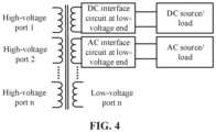
- the dual active bridge module 22 with the high-frequency isolation transformer may adopt a multi-port design and provide multiple power exchange interfaces outward, so as to achieve energy interaction between the main transformer, and DC power supplies and low-voltage AC and DC loads such as distributed photovoltaic and energy storage, which provides a convenient channel for access of distributed energy and energy supply of low-voltage loads around the high-voltage transformer substation, and makes operation of the whole device more flexible and reliable. As shown in FIG.
- the dual active bridge module 22 with the high-frequency isolation transformer includes n high-voltage ports and n low-voltage ports, and the number of ports may be flexibly expanded.
- One of the low-voltage ports is connected to the DC interface circuit at the low-voltage end, and another one of the low-voltage ports is connected to the AC interface circuit at the low-voltage end.
- the AC interface circuit at the low-voltage end and the DC interface circuit at the low-voltage end provide interfaces for the external AC and DC distributed power supply and loads to achieve the energy exchange between the main transformer, and the external power supply and loads. Port expansion of high and low voltages as well as AC and DC is easier and the operation manner is flexible and efficient.
- the high-frequency isolation transformer is adopted in the dual active bridge module 22 with the high-frequency isolation transformer, which greatly reduces the volume of the converter apparatus 2, making it possible to integrate the converter apparatus 2 into the transformer box and facilitating engineering applications.
- the operating frequency of the high-frequency isolation transformer is determined by the insulation level, capacity, occupation, and characteristics of the adopted power component of the converter apparatus 2.
- inverter modules 23 are cascaded to output a multi-level AC voltage, the amplitude and phase of which may be flexibly adjusted according to the Pulse Width Modulation (PWM) strategy.
- PWM Pulse Width Modulation
- the output end of the inverter module 23 is connected in series between the end of the winding and the neutral point.
- the absolute values of the voltages between the neutral point and the external terminals are equal.
- the common connection point of the head ends (or tail ends) of the three-phase coils is the neutral point, such as point N of the tertiary winding 13 in FIG. 3 .
- the coupling manner between the converter apparatus 2 and the main transformer 1 is as follows.
- the inverter module 23 of the converter apparatus 2 is connected in series between the end of the winding of the star connection of the main transformer 1 and the center point (or the ground) of the star connection of the main transformer 1.
- Such coupling manner applies to both of a high-voltage transmission system and a three-phase four-wire low-voltage distribution system.
- the inverter module 23 of the converter apparatus 2 may be connected in series to the end of the high-voltage winding or the end of the low-voltage winding.
- the inverter module 23 is connected in series between the end of the winding of the star connection of the power transformer and the center point (or the ground) of the star connection of the power transformer, the potential to ground is low, and the insulation requirement is low, which greatly reduces the insulation cost of the converter apparatus.
- the amplitude and phase of the voltage of the inverter module 23 are flexible and adjustable.
- the voltage of the primary winding and the voltage of each secondary winding of the main transformer 1 are changed by controlling the phase and amplitude of the output voltage of the inverter module 23.
- the input end of the converter apparatus 2 has a function of compensating the reactive power or harmonic current for the system through the tertiary energy-acquiring winding (i.e., the tertiary winding 13) while maintaining the DC voltage to be constant.
- the function of fast, arc-free and smooth voltage amplitude adjustment may be achieved.
- the phase angle of the voltage at the inlet side of the main transformer 1 may be changed, such that the power flow of the branch where the flexible power transformer is located is changed, and the power flow is adjusted.
- the inverter module 23 may have a harmonic voltage compensation function on the basis of achieving the adjustment of the voltage amplitude or phase.
- the flexible power transformer may adopt a voltage control mode or a power flow control mode.
- the port voltage and power flow of the flexible power transformer are controlled by controlling the amplitude and phase of the output voltage on the inverter side of the converter apparatus.
- a controllable voltage source is connected in series between the end of the winding of the star connection of the transformer and the center point (or the ground) of the star connection of the transformer.
- the busbar voltage of the AC system is denoted as u S .
- the voltage of the primary winding of the transformer is denoted as u 1 , and the number of turns is denoted as W 1 .
- the voltage of the secondary winding is denoted as u 2 , and the number of turns is denoted as W 2 .
- the voltage of the energy-acquiring winding (i.e., the tertiary winding) of the converter is denoted as u 3 , and the number of turns is denoted as W 3 .
- the output voltage of the controllable voltage source is denoted as u 4 .
- the voltage adjustment may be achieved.
- equations (1) and (2) the principle of the voltage adjustment is shown as equations (1) and (2).
- the voltage u 1 at both ends of the primary winding of the transformer may be adjusted by only adjusting the output voltage u 4 of the converter without changing the number of turns of the winding.
- the voltage u 2 induced at the side of the secondary winding also changes synchronously with the change of the voltage u 1 at both ends of the primary winding.
- the principle of power flow adjustment is shown as equations (3) to (8).
- the flexible power transformer may further achieve the power flow control for each line of multiple outlet lines.
- the transformer T1 is equivalent to a reactance X (converted to the primary side), and the part of the back-to-back converter connected in series to the transformer is equivalent to a controlled voltage source U ⁇ 4 .
- the active power P and the reactive power Q transmitted from the AC system to the load are as follows.
- P U 1 U 2 X sin ⁇ ⁇ 2
- Q U 1 U 1 ⁇ U 2 X cos ⁇ ⁇ 2
- the amplitude of the output voltage of the controllable voltage source is denoted as U 4
- the phase angle is denoted as ⁇ 4 .
- the active power P' and the reactive power Q' of the line are respectively as follows.
- P ′ U 1 ′ U 2 X sin ⁇ ⁇ ⁇ 2
- Q ′ U 1 ′ U 1 ′ ⁇ U 2 X cos ⁇ ⁇ ⁇ 2
- U' 1 and ⁇ are respectively as follows.
- FIG. 5 describes a phasor relationship of the voltage adjustment of the flexible power transformer.
- FIG. 6 describes an equivalent circuit of the flexible power transformer performing the power flow adjustment.
- the flexible power transformer further includes a bypass apparatus 3 connected in parallel at both ends of the inverter side of the converter apparatus 2.
- the bypass apparatus 3 includes an anti-parallel thyristor and a mechanical switch.
- the bypass apparatus 3 consists of the anti-parallel thyristor, the mechanical switch, etc., and the bypass apparatus 3 is connected in parallel at both ends of the inverter side of the converter apparatus 2.
- the output end of the bypass apparatus 3 is short-circuited, and the flexible power transformer operates as a conventional power transformer, which ensures reliability of the device.
Landscapes
- Engineering & Computer Science (AREA)
- Power Engineering (AREA)
- Inverter Devices (AREA)
- Ac-Ac Conversion (AREA)
Abstract
Description
- The application is based on and claims priority to
Chinese patent application No. 202210691872.1 filed on June 17, 2022 - The present application relates to the field of electrical devices of the power system, and in particular to a flexible power transformer.
- Under the background of "dual carbon", China has proposed to build a new power system with the new energy as the main body. Cleanliness of the structure of the power supply and power grid is accelerated, the grid-connected scale of new energy units gradually increase, and multiple ultra-high voltage alternating current (AC) and direct current (DC) projects are put into operation in succession. In the new power system, there are prominent problems that the power and voltage change rapidly and frequently, and the high/low voltage exceeds the limits, which are caused by factors such as large-scale replacement of conventional power supplies by volatile new energy, structure changes of the power grid frame, and load changes. Therefore, the ability of accepting a new energy power grid with high permeability and the long-distance transmission of the power grid are limited, which is not conducive to improving the quality of the power supply and reducing line losses. The safe, stable and economic operation of the power system is under great pressure, and it is urgent to improve the operation flexibility and regulation ability of the power grid.
- The power transformer is the central node of electrical energy transmission and connects different voltage levels. The regional voltage may be affected by adjusting the voltage of the transformer. The conventional voltage adjustment manner of the power transformer is mainly the mechanical loaded voltage adjustment, which may play the role of regional voltage adjustment in the power grid with the conventional synchronous generator as the main body. In the new power system, the connection of large-scale new energy and power electronic devices proposes the requirement of rapid and continuous voltage adjustment on the system. However, the mechanical loaded voltage adjustment transformer does not have the ability of continuous voltage adjustment, and the mechanical tap-changer has a slow adjustment speed and does not have the function of automatically adjusting the voltage. In addition, when the reactive power of the system is insufficient, by means of adjusting the tap joint of the transformer, only the voltage at the point where the transformer is located can be adjusted, and voltages in other regions are further reduced due to shortage of the reactive power, which can not adapt to the voltage adjustment requirement of the new power system with the new energy as the main body.
- In order to improve the consumption ability to the new energy of the new power system, maintain the voltage of the power grid to be stable, and improve the electrical energy quality of the power grid supply, it is urgent to carry out the research on the flexible power transformer technology in which the active part of the power electronics combines with the conventional electromagnetic transformers, so as to ensure the safe and reliable operation of the new energy power system with the new energy as the main body.
- In order to achieve the rapid, continuous and accurate adjustment of the voltage of the AC power transformer, improve the consumption ability to the new energy of the new power system, and ensure the reliable operation of the power grid, the present application provides a flexible power transformer.
- To achieve the above purpose, the present application provides the following technical solution.
- An embodiment of the present application provides a flexible power transformer. The flexible power transformer includes at least a main transformer and a converter apparatus. The main transformer includes a primary winding and multiple secondary windings. The converter apparatus is connected in series between an end of the primary winding of the main transformer and an end of any one of the multiple secondary windings of the main transformer, or the converter apparatus is connected in series between ends of any two of the multiple secondary windings of the main transformer. The converter apparatus is configured to adjust a voltage of each winding of the main transformer by adjusting an output voltage of the converter apparatus.
- In some embodiments, the converter apparatus may include multiple cascaded subunits. The subunits are configured to adjust an output voltage level of the converter apparatus by changing a number of the cascaded subunits.
- In some embodiments, the converter apparatus may be configured to control a port voltage and a power flow of the flexible power transformer by controlling an amplitude and a phase of an output voltage on the inverter side of the converter apparatus.
- In some embodiments, for each of the cascaded subunits, the subunit may include a rectifier module, a dual active bridge module with a high-frequency isolation transformer, and an inverter module. An input end of the rectifier module is connected to any one of the multiple secondary windings, and an output end of the rectifier module is connected to an input end of the dual active bridge module with the high-frequency isolation transformer. An input end of the inverter module is connected to an output end of the dual active bridge module with the high-frequency isolation transformer, and an output end of the inverter module is connected to an end of another one of the multiple secondary windings or the end of the primary winding.
- The rectifier module is configured to rectify an AC voltage provided by the secondary winding into a DC voltage, and maintain a DC voltage of each module in the converter apparatus to be stable.
- The dual active bridge module with the high-frequency isolation transformer is configured to perform a DC voltage conversion, transmit a converted DC voltage to the inverter module, and electrically isolate each module in the converter apparatus.
- The inverter module is configured to invert the converted DC voltage to an AC voltage, and transmit the AC voltage to the end of the another one of the multiple secondary windings or the end of the primary winding.
- In some embodiments, the inverter module may further be configured to change a voltage of the primary winding of the main transformer and a voltage of each secondary winding of the main transformer by controlling a phase and an amplitude of the output voltage of the inverter module.
- In some embodiments, the dual active bridge module with the high-frequency isolation transformer may have multiple ports. The multiple ports are configured to provide multiple power exchange interfaces outward.
- In some embodiments, an operating frequency of a high-frequency transformer in the dual active bridge module with the high-frequency isolation transformer may be determined by a capacity, an occupation, and characteristics of an adopted power component of the converter apparatus.
- In some embodiments, the output end of the inverter module may be connected in series between the end of the winding and a neutral point.
- In some embodiments, the flexible power transformer may further include a bypass apparatus connected in parallel at both ends of an inverter side of the converter apparatus.
- In some embodiments, the bypass apparatus may include an anti-parallel thyristor and a mechanical switch.
- The technical solution of the present application has the following advantages.
- The flexible power transformer provided by the present application includes a main transformer and a converter apparatus. The main transformer includes a primary winding and multiple secondary windings. The converter apparatus is connected in series between the end of the primary winding of the main transformer and the end of any one of the multiple secondary windings of the main transformer, or the converter apparatus is connected in series between the ends of any two of the multiple secondary windings of the main transformer. The voltage of each winding of the main transformer is adjusted by adjusting the output voltage of the converter apparatus. The converter apparatus is connected in series between the end of the primary winding of the main transformer and the end of any one of the multiple secondary windings of the main transformer, or the converter apparatus is connected in series between the ends of any two of the multiple secondary windings of the main transformer. The voltage of each winding of the main transformer is adjusted by adjusting the output voltage of the converter apparatus. The function of the adjustment of the voltage of each winding of the transformer may be achieved without changing the turn ratio of the transformer. In addition, the voltage source converter is combined with the power transformer to achieve the rapid, continuous, accurate and flexible adjustment of the output electrical quantity of the transformer with a converter having a smaller capacity, which has the advantages of arc-free switching, flexible control and fast response speed. In addition to controlling the voltage, it may also assist in controlling the power flow of the transformer.
- In order to illustrate the technical solution in the specific implementations of the present application or in the related art more clearly, drawings needed to be used in the description of the specific implementations or the related art would be briefly introduced below. It is apparent that the drawings described below are some implementations of the present application. For those of ordinary skill in the art, other drawings may also be obtained from these drawings without creative labor.
-
FIG. 1 is a schematic diagram of a specific example of a flexible power transformer according to an embodiment of the present application. -
FIG. 2 is a schematic diagram of another specific example of a flexible power transformer according to an embodiment of the present application. -
FIG. 3 is a diagram of a specific wiring of a flexible power transformer according to an embodiment of the present application. -
FIG. 4 is a wiring form of a high-frequency isolation transformer according to an embodiment of the present application. -
FIG. 5 is a diagram of a phasor relationship of voltage adjustment of a flexible power transformer according to an embodiment of the present application. -
FIG. 6 is an equivalent circuit of a flexible power transformer performing power flow adjustment according to an embodiment of the present application. - The technical solution of the present application will be clearly and completely described in combination with the drawings below. It is apparent that the described embodiments are a part of the embodiments of the present application, and not all the embodiments. Based on the embodiments in the present application, all other embodiments obtained by those of ordinary skill in the art without creative labor fall within the scope of protection of the present application.
- In the description of the present application, it is to be noted that the orientation or position relationship indicated by terms "center", "up", "down", "left", "right", "vertical", "horizontal", "inside", "outside", or the like, are based on the orientation or position relationship shown in the drawings, which are only for facilitating the description of the present application and simplifying the description, instead of indicating or implying that the apparatus or element referred to must have a particular orientation, or be constructed and operated in a particular orientation, and thus cannot be understood as a limitation on the present application. In addition, terms "first" "second" and "third" are only for descriptive purposes and can not be understood as indicating or implying a relative importance.
- In the description of the present application, it is to be noted that, unless otherwise explicitly specified and limited, terms "install", "link" and "connect" shall be understood broadly, and for example, may be a fixed connection, a detachable connection, or an integrated connection; may be a mechanical connection or an electrical connection; may be a direct connection, an indirect connection through an intermediate medium, or an internal connection between two elements; may be a wireless connection or a wired connection. For those of ordinary skill in the art, the specific meaning of the above terms in the present application may be understood according to specific conditions.
- In addition, technical features referred to in different implementations of the present application described below may be combined as long as they do not conflict with each other.
- An embodiment of the present application provides a flexible power transformer including a
main transformer 1 and aconverter apparatus 2. Themain transformer 1 includes a primary winding and multiple secondary windings. Theconverter apparatus 2 is connected in series between the end of the primary winding of themain transformer 1 and the end of any one of the multiple secondary windings of themain transformer 1, or theconverter apparatus 2 is connected in series between the ends of any two of the multiple secondary windings of themain transformer 1. The voltage of each winding of themain transformer 1 is adjusted by adjusting the output voltage of theconverter apparatus 2. - In some embodiments, as shown in
FIG. 1 orFIG. 2 , a case where themain transformer 1 includes a primary winding 11, a secondary winding 12, and a tertiary winding 13 is taken as an example for illustration. Here, the primary winding 11 is located on the primary side of themain transformer 1, and the secondary winding 12 and the tertiary winding 13 are located on the secondary side of themain transformer 1. An AC system is connected to the primary winding 11 of themain transformer 1 to supply power to themain transformer 1. The tertiary winding 13 is configured to supply power to theconverter apparatus 2. - In some embodiments, the primary winding 11 cooperates with the secondary winding 12 to complete a voltage conversion process. Here, the secondary winding 12 is responsible for outputting the voltage to supply energy to the lower-level line (i.e., the power grid) or the load. The tertiary winding 13 is connected to the input end of the
converter apparatus 2, and the tertiary winding 13 provides active power support for theconverter apparatus 2. - As shown in
FIG. 1 , theconverter apparatus 2 is connected in series between the end of the primary winding 11 of themain transformer 1 and the tertiary winding 13 of themain transformer 1. Here, voltages at both ends of the primary winding 11 may be adjusted by adjusting the output voltage of theconverter apparatus 2, and the output voltage of the secondary winding 12 may be synchronously changed, so as to achieve the rapid, continuous and accurate adjustment of the amplitude and phase of the voltage of themain transformer 1. In such case, each of the primary winding 11 and the tertiary winding 13 is of a star connection. The connection of the secondary winding 12 is not required, which may be flexibly selected according to the connection manner of the conventional power transformer based on application requirements of different scenarios. - As shown in
FIG. 2 , theconverter apparatus 2 is connected in series between the end of the secondary winding 12 of themain transformer 1 and the tertiary winding 13 of themain transformer 1. Here, voltages at both ends of the secondary winding 12 may be adjusted by adjusting the output voltage of theconverter apparatus 2, and the voltages at both ends of the primary winding 11 may be synchronously changed, so as to achieve the rapid, continuous and accurate adjustment of the amplitude and phase of the voltage of themain transformer 1. In such case, each of the secondary winding 12 and the tertiary winding 13 is of the star connection. The connection of the primary winding 11 is not required, which may be flexibly selected according to the connection manner of the conventional power transformer based on application requirements of different scenarios. - In the embodiments of the present application, as shown in
FIG. 3 , theconverter apparatus 2 with flexible adjustable voltage amplitude and phase may be connected in series between the end of the winding of the star connection of the power transformer and the center point (or the ground) of the star connection of the power transformer. The voltage of each winding of themain transformer 1 may be changed by adjusting theconverter apparatus 2, so as to replace the conventional mechanical transformer for the voltage adjustment and provide a certain phase shifting function. In addition, the tertiary winding provides active power support for theconverter apparatus 2, which achieves comprehensive functions of flexible control of the voltage/power flow, flexible port expansion and electrical energy quality compensation of the power transformer. - The present application provides a flexible power transformer. The converter apparatus is connected in series between the end of the primary winding of the main transformer and the end of any one of the multiple secondary windings of the main transformer, or the converter apparatus is connected in series between the ends of any two of the multiple secondary windings of the main transformer. The function of the adjustment of the voltage of each winding of the transformer may be achieved without changing the turn ratio of the transformer. In addition, the voltage source converter is combined with the power transformer to achieve the rapid, continuous, accurate and flexible adjustment of the output electrical quantity of the transformer with a converter having a smaller capacity. When the converter apparatus fails, the bypass apparatus bypasses the converter apparatus, and the main transformer may continue to operate normally. The flexible power transformer has advantages of arc-free switching, flexible control, fast response speed, low cost and high reliability.
- In some embodiments, as shown in
FIG. 3 , theconverter apparatus 2 includes multiple cascaded subunits. The output voltage level of the converter apparatus may be adjusted by changing the number of the cascaded subunits. - In some embodiments, the
converter apparatus 2 is achieved by multiple cascaded subunits, which can be applied to different voltage levels by changing the number of the cascaded subunits. In addition, the multiple cascaded subunits may achieve a multi-level inverter, reduce the harmonic content injected into the system, and is easy to expand, which may achieve an application of multiple voltage levels. With fully controlled power electronic components as the core, the subunit makes the amplitude and phase of the output voltage flexible and controllable, which greatly improves the response speed of on-load voltage adjustment, and may achieve long-term continuous operation, thereby providing a new solution for the voltage fluctuation problem caused by continuous fluctuation of the new energy. - In the embodiments of the present application, for each of the cascaded subunits, the subunit includes a
rectifier module 21, a dualactive bridge module 22 with a high-frequency isolation transformer, and an inverter module 23. Here, the input end of therectifier module 21 is connected to any one of the multiple secondary windings, and the output end of therectifier module 21 is connected to the input end of the dualactive bridge module 22 with the high-frequency isolation transformer. The input end of the inverter module 23 is connected to the output end of the dualactive bridge module 22 with the high-frequency isolation transformer, and the output end of the inverter module 23 is connected to the end of another one of the multiple secondary windings or the end of the primary winding. Here, therectifier module 21 is configured to rectify an AC voltage provided by the secondary winding connected to therectifier module 21 into a DC voltage, and maintain the DC voltage of each module in theconverter apparatus 2 to be stable. The dualactive bridge module 22 with the high-frequency isolation transformer is configured to perform a DC voltage conversion, transmit the converted DC voltage to the inverter module 23, and electrically isolate each module in theconverter apparatus 2. The inverter module 23 is configured to invert the converted DC voltage to an AC voltage, and transmit the AC voltage to the end of the another one of the multiple secondary windings or the end of the primary winding. - Specifically, as shown in
FIG. 3 , a case where theconverter apparatus 2 is connected in series between the end of the primary winding 11 of themain transformer 1 and the tertiary winding 13 of themain transformer 1 is taken as an example for illustration. The input end of therectifier module 21 is connected to the tertiary winding 13, and the output end of therectifier module 21 is connected to the input end of the dualactive bridge module 22 with the high-frequency isolation transformer. The output end of the dualactive bridge module 22 with the high-frequency isolation transformer is connected to the input end of the inverter module 23. The output end of the inverter module 23 is connected to the end of the primary winding 11. - Here, the tertiary winding 13 maintains the DC voltage in each module of the subunit to be stable through the
rectifier module 21. - Here, the dual
active bridge module 22 with the high-frequency isolation transformer has a function of DC voltage conversion, and achieves electrical isolation of each module in the subunit, which ensures scalability of the voltage level and the capacity of the flexible power transformer. The dualactive bridge module 22 with the high-frequency isolation transformer may adopt a multi-port design and provide multiple power exchange interfaces outward, so as to achieve energy interaction between the main transformer, and DC power supplies and low-voltage AC and DC loads such as distributed photovoltaic and energy storage, which provides a convenient channel for access of distributed energy and energy supply of low-voltage loads around the high-voltage transformer substation, and makes operation of the whole device more flexible and reliable. As shown inFIG. 4 , the dualactive bridge module 22 with the high-frequency isolation transformer includes n high-voltage ports and n low-voltage ports, and the number of ports may be flexibly expanded. One of the low-voltage ports is connected to the DC interface circuit at the low-voltage end, and another one of the low-voltage ports is connected to the AC interface circuit at the low-voltage end. The AC interface circuit at the low-voltage end and the DC interface circuit at the low-voltage end provide interfaces for the external AC and DC distributed power supply and loads to achieve the energy exchange between the main transformer, and the external power supply and loads. Port expansion of high and low voltages as well as AC and DC is easier and the operation manner is flexible and efficient. - In some embodiments, the high-frequency isolation transformer is adopted in the dual
active bridge module 22 with the high-frequency isolation transformer, which greatly reduces the volume of theconverter apparatus 2, making it possible to integrate theconverter apparatus 2 into the transformer box and facilitating engineering applications. The operating frequency of the high-frequency isolation transformer is determined by the insulation level, capacity, occupation, and characteristics of the adopted power component of theconverter apparatus 2. - Multiple inverter modules 23 are cascaded to output a multi-level AC voltage, the amplitude and phase of which may be flexibly adjusted according to the Pulse Width Modulation (PWM) strategy. By connecting the inverter module 23 in series to the end of the primary winding 11, the voltage of each winding may be changed to achieve the purpose of voltage adjustment without changing the turn ratio of the transformer.
- In some embodiments, as shown in
FIG. 3 , the output end of the inverter module 23 is connected in series between the end of the winding and the neutral point. Here, the absolute values of the voltages between the neutral point and the external terminals are equal. When the power supply side (the transformer or generator) or the load side is of a star connection, the common connection point of the head ends (or tail ends) of the three-phase coils is the neutral point, such as point N of the tertiary winding 13 inFIG. 3 . - In some embodiments, the coupling manner between the
converter apparatus 2 and themain transformer 1 is as follows. The inverter module 23 of theconverter apparatus 2 is connected in series between the end of the winding of the star connection of themain transformer 1 and the center point (or the ground) of the star connection of themain transformer 1. Such coupling manner applies to both of a high-voltage transmission system and a three-phase four-wire low-voltage distribution system. The inverter module 23 of theconverter apparatus 2 may be connected in series to the end of the high-voltage winding or the end of the low-voltage winding. The inverter module 23 is connected in series between the end of the winding of the star connection of the power transformer and the center point (or the ground) of the star connection of the power transformer, the potential to ground is low, and the insulation requirement is low, which greatly reduces the insulation cost of the converter apparatus. - In the embodiments of the present application, the amplitude and phase of the voltage of the inverter module 23 are flexible and adjustable. The voltage of the primary winding and the voltage of each secondary winding of the
main transformer 1 are changed by controlling the phase and amplitude of the output voltage of the inverter module 23. The input end of theconverter apparatus 2 has a function of compensating the reactive power or harmonic current for the system through the tertiary energy-acquiring winding (i.e., the tertiary winding 13) while maintaining the DC voltage to be constant. - In some embodiments, when the phase of the voltage of the inverter module 23 is the same as or reverse with the phase of the winding to which the inverter module 23 is connected in series, the function of fast, arc-free and smooth voltage amplitude adjustment may be achieved. When there is an angle difference between the phase of the output voltage of the inverter module 23 and the phase of the winding to which the inverter module 23 is connected in series, the phase angle of the voltage at the inlet side of the
main transformer 1 may be changed, such that the power flow of the branch where the flexible power transformer is located is changed, and the power flow is adjusted. The inverter module 23 may have a harmonic voltage compensation function on the basis of achieving the adjustment of the voltage amplitude or phase. - The flexible power transformer may adopt a voltage control mode or a power flow control mode. In the power flow control mode, the port voltage and power flow of the flexible power transformer are controlled by controlling the amplitude and phase of the output voltage on the inverter side of the converter apparatus.
- In some embodiments, principles of voltage adjustment and power flow control are as follows. A controllable voltage source is connected in series between the end of the winding of the star connection of the transformer and the center point (or the ground) of the star connection of the transformer. The busbar voltage of the AC system is denoted as u S . The voltage of the primary winding of the transformer is denoted as u 1, and the number of turns is denoted as W 1. The voltage of the secondary winding is denoted as u 2, and the number of turns is denoted as W 2. The voltage of the energy-acquiring winding (i.e., the tertiary winding) of the converter is denoted as u 3, and the number of turns is denoted as W 3 . The output voltage of the controllable voltage source is denoted as u 4. By adjusting the output voltage u 4 of the converter, the voltage adjustment may be achieved. With the equivalent circuit of the flexible power transformer performing the power flow adjustment, the principle of the voltage adjustment is shown as equations (1) and (2).


- According to the above equation (1), it can be known that the voltage u 1 at both ends of the primary winding of the transformer may be adjusted by only adjusting the output voltage u 4 of the converter without changing the number of turns of the winding. From the equation (2), it can be known that the voltage u 2 induced at the side of the secondary winding also changes synchronously with the change of the voltage u 1 at both ends of the primary winding.
- In some embodiments, the principle of power flow adjustment is shown as equations (3) to (8).
- The amplitude of the voltage of the AC system at the sending end is denoted as U 1, and the phase angle is 0. The amplitude of the voltage of the AC system at the receiving end is denoted as U 2, and the phase angle is denoted as δ 2. By changing the amplitude and phase angle of the output voltage on the inverter side of the converter, the flexible power transformer may further achieve the power flow control for each line of multiple outlet lines. The transformer T1 is equivalent to a reactance X (converted to the primary side), and the part of the back-to-back converter connected in series to the transformer is equivalent to a controlled voltage source U̇ 4.
- The active power P and the reactive power Q transmitted from the AC system to the load are as follows.


- The amplitude of the output voltage of the controllable voltage source is denoted as U 4, and the phase angle is denoted as δ 4. After the controllable voltage source is injected, the active power P' and the reactive power Q' of the line are respectively as follows.


- Here, U' 1 and ϕ are respectively as follows.


-
FIG. 5 describes a phasor relationship of the voltage adjustment of the flexible power transformer.FIG. 6 describes an equivalent circuit of the flexible power transformer performing the power flow adjustment. - In some embodiments, as shown in
FIG. 1 orFIG. 2 , the flexible power transformer further includes a bypass apparatus 3 connected in parallel at both ends of the inverter side of theconverter apparatus 2. - In some embodiments, the bypass apparatus 3 includes an anti-parallel thyristor and a mechanical switch. The bypass apparatus 3 consists of the anti-parallel thyristor, the mechanical switch, etc., and the bypass apparatus 3 is connected in parallel at both ends of the inverter side of the
converter apparatus 2. When theconverter apparatus 2 fails, the output end of the bypass apparatus 3 is short-circuited, and the flexible power transformer operates as a conventional power transformer, which ensures reliability of the device. - It is apparent that the above embodiments are only examples for clear illustration and are not a limitation on the implementations. For those of ordinary skill in the art, other changes or modifications in different forms may further be made based on the above illustration. Here, all the implementations need not to be, and cannot be exhaustive. Any apparent changes or modifications resulting therefrom remains within the scope of protection created by the present application.
Claims (10)
- A flexible power transformer, comprising at least a main transformer and a converter apparatus,wherein the main transformer comprises a primary winding and a plurality of secondary windings;the converter apparatus is connected in series between an end of the primary winding of the main transformer and an end of any one of the plurality of secondary windings of the main transformer, or the converter apparatus is connected in series between ends of any two of the plurality of secondary windings of the main transformer; andthe converter apparatus is configured to adjust a voltage of each winding of the main transformer by adjusting an output voltage of the converter apparatus.
- The flexible power transformer of claim 1, wherein the converter apparatus comprises a plurality of cascaded subunits, and the subunits are configured to adjust an output voltage level of the converter apparatus by changing a number of the cascaded subunits.
- The flexible power transformer of claim 2, wherein the converter apparatus is configured to control a port voltage and a power flow of the flexible power transformer by controlling an amplitude and a phase of an output voltage on an inverter side of the converter apparatus.
- The flexible power transformer of claim 2, wherein for each of the cascaded subunits, the subunit comprises a rectifier module, a dual active bridge module with a high-frequency isolation transformer, and an inverter module,wherein an input end of the rectifier module is connected to any one of the plurality of secondary windings, and an output end of the rectifier module is connected to an input end of the dual active bridge module with the high-frequency isolation transformer;an input end of the inverter module is connected to an output end of the dual active bridge module with the high-frequency isolation transformer, and an output end of the inverter module is connected to an end of another one of the plurality of secondary windings or the end of the primary winding;the rectifier module is configured to rectify an alternating current (AC) voltage provided by the secondary winding into a direct current (DC) voltage, and maintain a DC voltage of each module in the converter apparatus to be stable;the dual active bridge module with the high-frequency isolation transformer is configured to perform a DC voltage conversion, transmit a converted DC voltage to the inverter module, and electrically isolate each module in the converter apparatus; andthe inverter module is configured to invert the converted DC voltage to an AC voltage, and transmit the AC voltage to the end of the another one of the plurality of secondary windings or the end of the primary winding.
- The flexible power transformer of claim 4, wherein the inverter module is further configured to change a voltage of the primary winding of the main transformer and a voltage of each secondary winding of the main transformer by controlling a phase and an amplitude of an output voltage of the inverter module.
- The flexible power transformer of claim 4, wherein the dual active bridge module with the high-frequency isolation transformer has a plurality of ports, and the plurality of ports are configured to provide a plurality of power exchange interfaces outward.
- The flexible power transformer of claim 4, wherein an operating frequency of a high-frequency transformer in the dual active bridge module with the high-frequency isolation transformer is determined by a capacity, an occupation, and characteristics of an adopted power component of the converter apparatus.
- The flexible power transformer of claim 4, wherein the output end of the inverter module is connected in series between the end of the winding and a neutral point.
- The flexible power transformer of any one of claims 1 to 8, further comprising a bypass apparatus connected in parallel at both ends of an inverter side of the converter apparatus.
- The flexible power transformer of claim 9, wherein the bypass apparatus comprises an anti-parallel thyristor and a mechanical switch.
Applications Claiming Priority (2)
| Application Number | Priority Date | Filing Date | Title |
|---|---|---|---|
| CN202210691872.1A CN114884071A (en) | 2022-06-17 | 2022-06-17 | Flexible power transformer |
| PCT/CN2023/075686 WO2023241074A1 (en) | 2022-06-17 | 2023-02-13 | Flexible power transformer |
Publications (2)
| Publication Number | Publication Date |
|---|---|
| EP4531225A1 true EP4531225A1 (en) | 2025-04-02 |
| EP4531225A4 EP4531225A4 (en) | 2026-04-29 |
Family
ID=82682406
Family Applications (1)
| Application Number | Title | Priority Date | Filing Date |
|---|---|---|---|
| EP23822646.8A Pending EP4531225A4 (en) | 2022-06-17 | 2023-02-13 | FLEXIBLE POWER TRANSFORMER |
Country Status (3)
| Country | Link |
|---|---|
| EP (1) | EP4531225A4 (en) |
| CN (1) | CN114884071A (en) |
| WO (1) | WO2023241074A1 (en) |
Families Citing this family (8)
| Publication number | Priority date | Publication date | Assignee | Title |
|---|---|---|---|---|
| CN114884071A (en) * | 2022-06-17 | 2022-08-09 | 国网智能电网研究院有限公司 | Flexible power transformer |
| CN116345532A (en) * | 2022-12-27 | 2023-06-27 | 三峡电能有限公司 | Open winding structure flexible looped network controller |
| CN117595383B (en) * | 2023-12-25 | 2025-04-25 | 电子科技大学 | Control method of multi-port photovoltaic and energy storage combined power generation system based on duty cycle |
| CN118100261B (en) * | 2024-02-01 | 2025-06-24 | 国网湖北省电力有限公司经济技术研究院 | A flexible distribution transformer topology for taking energy from high voltage ports and its control method |
| US20250253094A1 (en) * | 2024-02-02 | 2025-08-07 | Rockwell Collins, Inc. | Radiation hardened active power transformer |
| CN118137859B (en) * | 2024-05-08 | 2024-08-09 | 东北电力大学 | Direct type AC/AC-HV type hybrid distribution transformer |
| CN119480394A (en) * | 2025-01-14 | 2025-02-18 | 佛山市顺德区伊戈尔电力科技有限公司 | A power conversion system and distribution transformer |
| CN120049441B (en) * | 2025-04-18 | 2025-08-15 | 国网福建省电力有限公司电力科学研究院 | Hybrid distribution transformer integrating on-load voltage regulating switch and series-parallel converter and voltage control method |
Family Cites Families (12)
| Publication number | Priority date | Publication date | Assignee | Title |
|---|---|---|---|---|
| US5949221A (en) * | 1998-05-21 | 1999-09-07 | Siemens Westinghouse Power Corporation | Line powered, primary side connected apparatus injecting voltage compensation into an electric power line using one transformer |
| RO122237B1 (en) * | 2005-11-24 | 2009-02-27 | Adrian Traian Pleşca | Stabilized mono-phase modular switch, for voltage adjustment under load |
| WO2010091260A2 (en) * | 2009-02-06 | 2010-08-12 | Abb Research Ltd. | A hybrid distribution transformer with ac & dc power capabilities |
| CN105006978A (en) * | 2015-08-26 | 2015-10-28 | 南方电网科学研究院有限责任公司 | On-load tap changer for distribution transformers |
| CN110086355B (en) * | 2019-04-29 | 2020-05-22 | 西安交通大学 | High-frequency control compensation type controllable alternating current distribution transformer |
| JP7291639B2 (en) * | 2020-01-16 | 2023-06-15 | 株式会社ダイヘン | on-load tap changer |
| CN111525582B (en) * | 2020-06-10 | 2025-10-21 | 全球能源互联网研究院有限公司 | A flexible AC active voltage regulation device and method |
| CN111525583B (en) * | 2020-06-16 | 2025-09-16 | 全球能源互联网研究院有限公司 | Voltage regulating transformer and power flow control system |
| CN112072639B (en) * | 2020-08-11 | 2022-04-08 | 东南大学 | Module-shared power grid flexible closed-loop controller topology |
| CN213585598U (en) * | 2020-11-27 | 2021-06-29 | 全球能源互联网研究院有限公司 | Multi-port power electronic transformer topological structure and alternating current-direct current micro-grid system thereof |
| CN112886827B (en) * | 2021-02-01 | 2022-06-03 | 中科兆和电力技术(山东)有限公司 | Half-capacity cophase power supply converter |
| CN114884071A (en) * | 2022-06-17 | 2022-08-09 | 国网智能电网研究院有限公司 | Flexible power transformer |
-
2022
- 2022-06-17 CN CN202210691872.1A patent/CN114884071A/en active Pending
-
2023
- 2023-02-13 WO PCT/CN2023/075686 patent/WO2023241074A1/en not_active Ceased
- 2023-02-13 EP EP23822646.8A patent/EP4531225A4/en active Pending
Also Published As
| Publication number | Publication date |
|---|---|
| WO2023241074A1 (en) | 2023-12-21 |
| EP4531225A4 (en) | 2026-04-29 |
| CN114884071A (en) | 2022-08-09 |
Similar Documents
| Publication | Publication Date | Title |
|---|---|---|
| EP4531225A1 (en) | Flexible power transformer | |
| US11431263B2 (en) | Solid-state transformer having uninterrupted operation ability under AC/DC fault and control method thereof | |
| Bahrman et al. | The ABCs of HVDC transmission technologies | |
| CN112821403B (en) | A single-phase or three-phase electromagnetic series transmission line power flow control topology circuit | |
| KR20130006613A (en) | Static var compensator with multilevel converter | |
| CN101795072A (en) | High-voltage direct-current direct-current (HVDC-DC) power electronic converter transformer | |
| EP1078434B1 (en) | Power inverter apparatus using the load transformer of an ac power line to insert series compensation | |
| Venkataramanan et al. | A superconducting DC transmission system based on VSC transmission technologies | |
| KR20210150852A (en) | Hybrid semiconductor transformer | |
| CN102222921A (en) | Capacitor clamping-based trilevel railway power regulator | |
| CN107093907A (en) | Auto-transformer adjusts the compensation device of reactive capability | |
| CN112952845A (en) | Low-frequency power transmission system with transformer isolation and control method thereof | |
| US3942089A (en) | D.C. voltage transformation in high tension systems | |
| JP2000228826A (en) | Power supply equipment by quality | |
| CN115173422B (en) | Interconnection type power supply transformer and regulation and control method thereof | |
| Lopes et al. | A PWM quadrature-booster phase shifter for AC power transmission | |
| CN214707171U (en) | Low-frequency power transmission system with transformer isolation | |
| EP4542807A1 (en) | Flexible alternating-current interconnection apparatus and startup control method | |
| Pan et al. | Urban power grid enhancement and modernization with VSC-HVDC interties | |
| CN109038606B (en) | On-load voltage regulating transformer and unified power flow control system | |
| CN103701113B (en) | Power flow control device | |
| RU2489791C1 (en) | Method of distributing power in multilevel frequency converter for powering synchronous and asynchronous motors | |
| CN107171270B (en) | Intensive ice melting device constant current, constant voltage modular dynamic reactive power compensation components | |
| CN117458573A (en) | A regional power quality management system and control method | |
| Yu et al. | A three-port input-series and output-parallel DC-DC converter with distributed control for medium-voltage DC distribution system |
Legal Events
| Date | Code | Title | Description |
|---|---|---|---|
| STAA | Information on the status of an ep patent application or granted ep patent |
Free format text: STATUS: THE INTERNATIONAL PUBLICATION HAS BEEN MADE |
|
| PUAI | Public reference made under article 153(3) epc to a published international application that has entered the european phase |
Free format text: ORIGINAL CODE: 0009012 |
|
| STAA | Information on the status of an ep patent application or granted ep patent |
Free format text: STATUS: REQUEST FOR EXAMINATION WAS MADE |
|
| 17P | Request for examination filed |
Effective date: 20241223 |
|
| AK | Designated contracting states |
Kind code of ref document: A1 Designated state(s): AL AT BE BG CH CY CZ DE DK EE ES FI FR GB GR HR HU IE IS IT LI LT LU LV MC ME MK MT NL NO PL PT RO RS SE SI SK SM TR |
|
| DAV | Request for validation of the european patent (deleted) | ||
| DAX | Request for extension of the european patent (deleted) | ||
| A4 | Supplementary search report drawn up and despatched |
Effective date: 20260331 |
|
| RIC1 | Information provided on ipc code assigned before grant |
Ipc: H02J 3/12 20060101AFI20260325BHEP Ipc: H02J 3/06 20060101ALI20260325BHEP Ipc: H02M 5/12 20060101ALI20260325BHEP Ipc: H02M 1/00 20060101ALI20260325BHEP Ipc: H02M 1/12 20060101ALI20260325BHEP Ipc: H02M 1/32 20070101ALI20260325BHEP Ipc: H02M 3/335 20060101ALI20260325BHEP Ipc: H02M 5/45 20060101ALI20260325BHEP Ipc: H02M 7/48 20070101ALI20260325BHEP |