EP4531211A1 - Terminal scurring - Google Patents
Terminal scurring Download PDFInfo
- Publication number
- EP4531211A1 EP4531211A1 EP23199580.4A EP23199580A EP4531211A1 EP 4531211 A1 EP4531211 A1 EP 4531211A1 EP 23199580 A EP23199580 A EP 23199580A EP 4531211 A1 EP4531211 A1 EP 4531211A1
- Authority
- EP
- European Patent Office
- Prior art keywords
- cable
- section
- clamp
- terminal
- opening
- Prior art date
- Legal status (The legal status is an assumption and is not a legal conclusion. Google has not performed a legal analysis and makes no representation as to the accuracy of the status listed.)
- Pending
Links
Images


Classifications
-
- H—ELECTRICITY
- H01—ELECTRIC ELEMENTS
- H01R—ELECTRICALLY-CONDUCTIVE CONNECTIONS; STRUCTURAL ASSOCIATIONS OF A PLURALITY OF MUTUALLY-INSULATED ELECTRICAL CONNECTING ELEMENTS; COUPLING DEVICES; CURRENT COLLECTORS
- H01R4/00—Electrically-conductive connections between two or more conductive members in direct contact, i.e. touching one another; Means for effecting or maintaining such contact; Electrically-conductive connections having two or more spaced connecting locations for conductors and using contact members penetrating insulation
- H01R4/70—Insulation of connections
-
- H—ELECTRICITY
- H01—ELECTRIC ELEMENTS
- H01R—ELECTRICALLY-CONDUCTIVE CONNECTIONS; STRUCTURAL ASSOCIATIONS OF A PLURALITY OF MUTUALLY-INSULATED ELECTRICAL CONNECTING ELEMENTS; COUPLING DEVICES; CURRENT COLLECTORS
- H01R13/00—Details of coupling devices of the kinds covered by groups H01R12/70 or H01R24/00 - H01R33/00
- H01R13/46—Bases; Cases
- H01R13/52—Dustproof, splashproof, drip-proof, waterproof, or flameproof cases
- H01R13/5202—Sealing means between parts of housing or between housing part and a wall, e.g. sealing rings
-
- H—ELECTRICITY
- H01—ELECTRIC ELEMENTS
- H01R—ELECTRICALLY-CONDUCTIVE CONNECTIONS; STRUCTURAL ASSOCIATIONS OF A PLURALITY OF MUTUALLY-INSULATED ELECTRICAL CONNECTING ELEMENTS; COUPLING DEVICES; CURRENT COLLECTORS
- H01R4/00—Electrically-conductive connections between two or more conductive members in direct contact, i.e. touching one another; Means for effecting or maintaining such contact; Electrically-conductive connections having two or more spaced connecting locations for conductors and using contact members penetrating insulation
- H01R4/28—Clamped connections, spring connections
- H01R4/30—Clamped connections, spring connections utilising a screw or nut clamping member
- H01R4/34—Conductive members located under head of screw
-
- H—ELECTRICITY
- H02—GENERATION; CONVERSION OR DISTRIBUTION OF ELECTRIC POWER
- H02G—INSTALLATION OF ELECTRIC CABLES OR LINES, OR OF COMBINED OPTICAL AND ELECTRIC CABLES OR LINES
- H02G15/00—Cable fittings
- H02G15/02—Cable terminations
- H02G15/06—Cable terminating boxes, frames or other structures
-
- H—ELECTRICITY
- H01—ELECTRIC ELEMENTS
- H01R—ELECTRICALLY-CONDUCTIVE CONNECTIONS; STRUCTURAL ASSOCIATIONS OF A PLURALITY OF MUTUALLY-INSULATED ELECTRICAL CONNECTING ELEMENTS; COUPLING DEVICES; CURRENT COLLECTORS
- H01R11/00—Individual connecting elements providing two or more spaced connecting locations for conductive members which are, or may be, thereby interconnected, e.g. end pieces for wires or cables supported by the wire or cable and having means for facilitating electrical connection to some other wire, terminal, or conductive member, blocks of binding posts
- H01R11/11—End pieces or tapping pieces for wires, supported by the wire and for facilitating electrical connection to some other wire, terminal or conductive member
- H01R11/12—End pieces terminating in an eye, hook, or fork
-
- H—ELECTRICITY
- H01—ELECTRIC ELEMENTS
- H01R—ELECTRICALLY-CONDUCTIVE CONNECTIONS; STRUCTURAL ASSOCIATIONS OF A PLURALITY OF MUTUALLY-INSULATED ELECTRICAL CONNECTING ELEMENTS; COUPLING DEVICES; CURRENT COLLECTORS
- H01R13/00—Details of coupling devices of the kinds covered by groups H01R12/70 or H01R24/00 - H01R33/00
- H01R13/46—Bases; Cases
- H01R13/52—Dustproof, splashproof, drip-proof, waterproof, or flameproof cases
- H01R13/5205—Sealing means between cable and housing, e.g. grommet
-
- H—ELECTRICITY
- H01—ELECTRIC ELEMENTS
- H01R—ELECTRICALLY-CONDUCTIVE CONNECTIONS; STRUCTURAL ASSOCIATIONS OF A PLURALITY OF MUTUALLY-INSULATED ELECTRICAL CONNECTING ELEMENTS; COUPLING DEVICES; CURRENT COLLECTORS
- H01R13/00—Details of coupling devices of the kinds covered by groups H01R12/70 or H01R24/00 - H01R33/00
- H01R13/46—Bases; Cases
- H01R13/52—Dustproof, splashproof, drip-proof, waterproof, or flameproof cases
- H01R13/5213—Covers
Definitions
- the invention relates to a terminal housing for housing an electric power terminal and a cable shoe.
- the invention further relates to a motor controller system, which comprises a power terminal, a cable with a cable shoe and such a terminal housing.
- a known prior art terminal housing is disclosed in EP3940907A1 .
- the housing has a screw opening for the insertion of a screw, wherein the terminal housing further comprises corresponding receptacles for receiving a sealing element for the outer opening and the screw opening.
- the terminal housing further comprises a cover, which removably covers the screw opening. The cover is attached to the clamp section by a form fit connection.
- the terminal housing according to the invention as defined in claim 1 has its object to provide an improved or alternative terminal housing whereby the cover of the terminal housing can be removed and refitted multiple times with a reduced risk of damage to the cover resulting in inadequate sealing of the terminal contact from the environment.
- the terminal housing for housing a power terminal and a cable shoe connected to the power terminal.
- the terminal housing has a clamp section, which runs in an axial direction and a circumferential direction and comprises a clamp section wall which delimits a clamp volume for housing the power terminal and the cable shoe, and a cable section for the insertion of a cable connected to the cable shoe.
- the cable section projects from the clamp section in a direction transverse or inclined to the axial direction and delimits a cable volume.
- the cable section comprises an inner opening, for the insertion of the cable shoe into the clamp volume, and an outer opening opposing the inner opening, for the insertion of the cable into the cable section.
- the clamp section comprises a screw opening spaced from the cable section and open in the axial direction, for the insertion of a screw into the clamp volume, and a cover, which removably covers the screw opening.
- the clamp section further comprises a terminal opening opposing the screw opening, for the insertion of the power terminal into the clamp volume.
- the terminal housing comprises a cover sealing receptacle, for receiving a cover sealing element for sealing the clamp volume to the outside, the cover sealing receptacle is delimited by the clamp section and the cover.
- the cover is attached to the clamp section via at least one snap fit connection, which is provided by at least one resilient cantilever arm which extends from the cover, and comprises a protrusion at its free end, which extends into a complementary recess or opening provided on the clamp section or on the cable section.
- the snap fit connection can be provided by at least one resilient cantilever arm which extends from the clamp section or on the cable section and extends into a complementary recess or opening provided on the cover.
- the connection of the cover to the clamp section is not achieved solely by a form fit connection. Indeed the cover can be also attached to the clamp section without a form fit connection. It is only important that there is sufficient sealing between the cover and the clamp section.
- the cover can be attached to the clamp section by pressing in the axial direction, and can be removed for example by using a tool to disengage the snap fit. Due to the use of at least one resilient cantilever arm for the snap fit connection the cover can be opened and closed multiple times reducing the risk of damaging the cover.
- the recess or opening is preferably arranged spaced from the clamp section wall, so that the disengagement of the snap fit connection can be achieved without damaging the critical sealing part of the cover, so that a secure attachment of the cover is achieved whilst enabling repeated attaching and removing of the cover.
- the directions indicated herein refer in particular to the axial direction, which can correspond to the projection direction of the power terminal.
- the radial direction, or the term "radial”, thus means transverse to the axial direction.
- the circumferential direction runs about the axial direction.
- the cover preferably comprises a first projection which extends away from the clamp section transversely or inclined to the axial direction, wherein the at least one resilient cantilever arm is connected at one end to the first projection and extending perpendicular therefrom in the axial direction and comprises the protrusion at its free end, which extends into a complementary recess or opening provided on the clamp section or on the cable section.
- the resilient cantilever arms deform elastically when the snap fit engages or is disengaged. The snap fit connection is thus located away from the sealing area of the cover such that damage to the sealing area is avoided.
- Two such resilient cantilever arms can be provided, in this case the protrusions at the free ends of the cantilever arms can be facing each other and each extending into a respective complementary recess or opening provided on the clamp section or on the cable section.
- the resilient arms must be pushed apart using a tool to disengage the snap fit, thus making the attachment more secure preventing inadvertent removal of the cover.
- the second projection can be snap-fitted in the complementary opening or recess provided on the clamp section.
- the terminal housing 1 further comprises a cable sealing receptacle 29 within the cable volume 9, for receiving a cable sealing element 30 for sealing the cable volume 9 to the outside.
- the cable sealing receptacle 29 is delimited by the cable section 7 and is arranged in the region of the outer opening 11.
- the cable section 7 comprises a radial enlargement in the region of the outer opening 11, which delimits the cable sealing receptacle 29.
- the cable sealing element 30 is a generally cylindrical rubber part with sealing fins.
Landscapes
- Connector Housings Or Holding Contact Members (AREA)
- Connections By Means Of Piercing Elements, Nuts, Or Screws (AREA)
- Motor Or Generator Frames (AREA)
Abstract
Terminal housing (1) for housing a power terminal (2) and a cable shoe (3) connected to the power terminal (2). The terminal housing (1) has a clamp section (4) having a clamp section wall (37) which delimits a clamp volume (6) for housing the power terminal (2) and the cable shoe (3). The clamp section (4) comprises a screw opening (12) which is open in the axial direction (5). A cover (14) removably covers the screw opening (12), wherein the cover (14) is attached to the clamp section (4) via at least one snap fit connection (20). The snap fit connection (20) being provided by at least one resilient cantilever arm (22).
Description
- The invention relates to a terminal housing for housing an electric power terminal and a cable shoe. The invention further relates to a motor controller system, which comprises a power terminal, a cable with a cable shoe and such a terminal housing.
- A known prior art terminal housing is disclosed in
EP3940907A1 . This discloses a terminal housing, which comprises a terminal opening for the insertion of the power terminal, and further comprises an outer opening for the insertion of the cable shoe. The housing has a screw opening for the insertion of a screw, wherein the terminal housing further comprises corresponding receptacles for receiving a sealing element for the outer opening and the screw opening. The terminal housing further comprises a cover, which removably covers the screw opening. The cover is attached to the clamp section by a form fit connection. - The terminal housing according to the invention as defined in
claim 1 has its object to provide an improved or alternative terminal housing whereby the cover of the terminal housing can be removed and refitted multiple times with a reduced risk of damage to the cover resulting in inadequate sealing of the terminal contact from the environment. - This object is achieved according to a first aspect of the invention with a terminal housing for housing a power terminal and a cable shoe connected to the power terminal. The terminal housing has a clamp section, which runs in an axial direction and a circumferential direction and comprises a clamp section wall which delimits a clamp volume for housing the power terminal and the cable shoe, and a cable section for the insertion of a cable connected to the cable shoe. The cable section projects from the clamp section in a direction transverse or inclined to the axial direction and delimits a cable volume. The cable section comprises an inner opening, for the insertion of the cable shoe into the clamp volume, and an outer opening opposing the inner opening, for the insertion of the cable into the cable section. The clamp section comprises a screw opening spaced from the cable section and open in the axial direction, for the insertion of a screw into the clamp volume, and a cover, which removably covers the screw opening. The clamp section further comprises a terminal opening opposing the screw opening, for the insertion of the power terminal into the clamp volume. The terminal housing comprises a cover sealing receptacle, for receiving a cover sealing element for sealing the clamp volume to the outside, the cover sealing receptacle is delimited by the clamp section and the cover. The cover is attached to the clamp section via at least one snap fit connection, which is provided by at least one resilient cantilever arm which extends from the cover, and comprises a protrusion at its free end, which extends into a complementary recess or opening provided on the clamp section or on the cable section. Alternatively the snap fit connection can be provided by at least one resilient cantilever arm which extends from the clamp section or on the cable section and extends into a complementary recess or opening provided on the cover.
- By using a snap fit connection, the connection of the cover to the clamp section is not achieved solely by a form fit connection. Indeed the cover can be also attached to the clamp section without a form fit connection. It is only important that there is sufficient sealing between the cover and the clamp section. By having a snap fit connection the cover can be attached to the clamp section by pressing in the axial direction, and can be removed for example by using a tool to disengage the snap fit. Due to the use of at least one resilient cantilever arm for the snap fit connection the cover can be opened and closed multiple times reducing the risk of damaging the cover.
- The recess or opening is preferably arranged spaced from the clamp section wall, so that the disengagement of the snap fit connection can be achieved without damaging the critical sealing part of the cover, so that a secure attachment of the cover is achieved whilst enabling repeated attaching and removing of the cover.
- The directions indicated herein refer in particular to the axial direction, which can correspond to the projection direction of the power terminal. The radial direction, or the term "radial", thus means transverse to the axial direction. The circumferential direction runs about the axial direction.
- The cover preferably comprises a first projection which extends away from the clamp section transversely or inclined to the axial direction, wherein the at least one resilient cantilever arm is connected at one end to the first projection and extending perpendicular therefrom in the axial direction and comprises the protrusion at its free end, which extends into a complementary recess or opening provided on the clamp section or on the cable section. The resilient cantilever arms deform elastically when the snap fit engages or is disengaged. The snap fit connection is thus located away from the sealing area of the cover such that damage to the sealing area is avoided.
- Two such resilient cantilever arms can be provided, in this case the protrusions at the free ends of the cantilever arms can be facing each other and each extending into a respective complementary recess or opening provided on the clamp section or on the cable section. In this arrangement the resilient arms must be pushed apart using a tool to disengage the snap fit, thus making the attachment more secure preventing inadvertent removal of the cover.
- The cover can further comprise at least one reinforcing rib extending along a surface of the first projection opposing the cantilever arms. The rib reinforces the cover further reducing risk of damage during removal of the cover.
- The protrusions can have a first stop surface which extends in a plane extending perpendicularly to the axial direction and engages with an opposing parallel stop surface of the recess or opening. With this arrangement of stop surface it necessary to apply a lateral force to the cantilever arms to disengage the snap fit before moving the cover axially away from the clamp section.
- A second projection can be provided on the cover which extends away from the clamp section transversely or inclined to the axial direction. The second projection is preferably arranged on an opposite side of the cover to the first projection, wherein the second projection extends into a complementary opening or recess provided on the clamp section. The second projection aids locating the cover into the clamp section, and provides a more secure attachment of the cover.
- The second projection can be snap-fitted in the complementary opening or recess provided on the clamp section.
- The terminal housing can further comprise a cable sealing receptacle within the cable volume, for receiving a cable sealing element for sealing the cable volume to the outside, the cable sealing receptacle is delimited by the cable section and arranged in the region of the outer opening.
- The terminal housing can further comprise a terminal sealing receptacle arranged in the region of the terminal opening for receiving a terminal sealing element for sealing the clamp volume to the outside. The terminal sealing receptacle can be delimited by a groove that is open on the side averted from the clamp volume.
- In a preferred embodiment the cover comprises a section extending into the clamp volume, the section having a groove which delimits the sealing receptacle for receiving a cover sealing element. The section can be in the form of a collar, preferably a cylindrical collar.
- A motor controller can be provided with a terminal housing according to one of the above embodiments of the invention described above. The motor controller comprises an axially projecting power terminal, wherein the power terminal projects axially into the clamp section of the terminal housing through the terminal opening. A cable with a cable shoe extends into the terminal housing through the outer opening, such that the cable shoe is arranged in the clamp volume on the side of the power terminal facing the screw opening, and a screw extends through the cable shoe into the power terminal, such that the cable shoe is clamped between the screw and the power terminal.
- Embodiments will now be described by way of example only with reference to the accompanying drawings, in which:
-
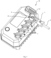
Figure 1 is a perspective view of a terminal housing according to the invention. -
Figure 2 is a cross section view of a terminal housing according tofigure 1 -
Figure 3 is an exploded view of a terminal housing according to the invention. -
Figure 4 is a cross section view taken through the line A-A infigure 2 . -
Figure 5 is a perspective view of a motor controller according to the invention. - Referring to the
figures 1 to 5 , aterminal housing 1 is provided for housing apower terminal 2 together with acable shoe 3. Theterminal housing 1 has aclamp section 4 which runs in anaxial direction 5 and a circumferential direction and comprises aclamp section wall 37 which delimits aclamp volume 6 for housing thepower terminal 2 and thecable shoe 3. Theterminal housing 1 has acable section 7 for the insertion of acable 8 connected to thecable shoe 3. As can be seen infigure 2 , thecable section 7 projects from theclamp section 4 in a direction transverse to the axial direction and delimits acable volume 9. Thecable section 7 comprises aninner opening 10 for the insertion of thecable shoe 3 into theclamp volume 9. Thecable section 7 also comprises anouter opening 11 opposing theinner opening 10, for the insertion of thecable 8 into thecable section 7. - The
clamp section 4 comprises a screw opening 12 spaced from thecable section 7 and open in theaxial direction 5. Ascrew 13 can be inserted through theopening 12 intoclamp volume 6. Thecable 8 with acable shoe 3 extends into theterminal housing 1 through theouter opening 11, such that thecable shoe 3 is arranged in theclamp volume 6 on the side of thepower terminal 2 facing thescrew opening 12. Thescrew 13 extends through thecable shoe 3 into thepower terminal 2, such that thecable shoe 3 is clamped between thescrew 13 and thepower terminal 2. Afirst cover 14 is provided, which covers thescrew opening 12. Thefirst cover 14 is removably attached to theclamp section 4. - The
clamp section 4 further comprises aterminal opening 15 opposing thescrew opening 12 for the insertion of thepower terminal 2 into theclamp volume 6. Theterminal housing 1 comprises a cover sealing receptacle 16 for receiving acover sealing element 17 for sealing theclamp volume 6 to the outside, the cover sealing receptacle 16 is delimited by theclamp section 7 and thefirst cover 14. For this purpose, thecover 14 comprises asection 18 extending into theclamp volume 6. Thesection 18 can be in the form of a collar, preferably acylindrical collar 18. Thecollar 18 has a groove 19 which delimits the sealing receptacle. - According to the invention the
cover 14 is attached to theclamp section 4 via a snapfit connection 20. The snap-fit connection is a connection via interlocking parts of thecover 14 and theclamp section 4 or thecable section 7. The snap-fit connection 20 is in the form of a cantilever snap-fit, whereby in the embodiment show an elasticallydeformable cantilever arm 22 is provided on thecover 14. The elasticallydeformable cantilever arm 22 could however also be formed on theclamp section 4 or on thecable section 7. By using a snapfit connection 20 with acantilever arm 22, the connection of the cover to the clamp section is not achieved solely by a form fit connection, and the cantilever arm enables repeated attaching and removing of the cover whilst minimizing damage to the sealing parts of thecover 14. Thecover 14 can be also attached to theclamp section 4 without a form fit connection. It is only important that there is sufficient sealing between thecover 14 and theclamp section 4 in order to seal theclamp volume 6 from the outside. Thecover 14 can be attached to the clamp section by pressing in theaxial direction 5, and can be removed for example by using a tool to disengage the snap fit. - In the embodiment shown, the snap
fit connection 20 is provided by afirst projection 21 on thecover 14 which extends away from theclamp section 4 transversely or inclined to theaxial direction 5, and which has tworesilient cantilever arms 22 connected at one end to thefirst projection 21. The tworesilient cantilever arms 22 extend perpendicular fromfirst projection 21 in theaxial direction 5 and each comprise aprotrusion 23 at their free end, which extends into acomplementary recess 24 or opening provided on theclamp section 4 or on thecable section 7. Theresilient cantilever arms 22 deform elastically when the snap fit engages or is disengaged. The snapfit connection 20 is thus located away from the sealing area of the cover such that damage to the sealing area is avoided. - The
cover 14 can further comprise at least one reinforcing rib extending along a surface of thefirst projection 21 opposing thecantilever arms 22. - In the embodiment shown, the
protrusions 23 at the free ends of thecantilever arms 22 are facing each other and each extends into a respective complementary recess or opening 24 provided on theclamp section 4 or on thecable section 7. Theprotrusions 23 have afirst stop surface 25 which extends in a plane extending perpendicularly to theaxial direction 5 and engages with an opposing parallel second stop surface 26 of the recess oropening 24. In this arrangement theresilient arms 22 must be pushed apart using a tool to disengage the snap fit, thus making the attachment more secure preventing inadvertent removal of the cover. Theprotrusions 23 can be tapered to aid deflection of thecantilever arms 22 when engaging the snap fit. - A
second projection 27 is provided on thecover 14 which extends away from theclamp section 4 transversely or inclined to theaxial direction 5. Thesecond projection 27 is arranged on an opposite side of thecover 14 to thefirst projection 21, wherein thesecond projection 27 extends into acomplementary opening 28 or recess provided on theclamp section 4. Thesecond projection 27 aids locating thecover 14 into theclamp section 4, and provides a more secure attachment of thecover 14. Thesecond projection 27 can be snap-fitted in thecomplementary opening 28 or recess provided on theclamp section 14. - The
terminal housing 1 further comprises acable sealing receptacle 29 within thecable volume 9, for receiving acable sealing element 30 for sealing thecable volume 9 to the outside. Thecable sealing receptacle 29 is delimited by thecable section 7 and is arranged in the region of theouter opening 11. In particular thecable section 7 comprises a radial enlargement in the region of theouter opening 11, which delimits thecable sealing receptacle 29. Thecable sealing element 30 is a generally cylindrical rubber part with sealing fins. - The
terminal housing 1 also has a terminal sealing receptacle 31 (seefigure 2 ) arranged in the region of theterminal opening 15 for receiving aterminal sealing element 32 for sealing theclamp volume 9 to the outside. Theterminal sealing receptacle 31 is delimited by a groove that is open on the side averted from theclamp volume 9. - The cable shoe comprises a
base 35 and asleeve 34. Thesleeve 34 receives an end of thecable 8, and thebase 35 extends from thesleeve 34 and has an opening for attachment to thepower terminal 2 via thescrew 13. Thecable volume 6 decreases towards theinner opening 10 such that thebase 35 of thecable shoe 3 is guided into theclamp volume 6 through theinner opening 10. - The
terminal housing 1 further comprises asecond cover 36 arranged at theouter opening 11 for fixing thecable 8 to theterminal housing 1. Thesecond cover 36 is snap-fitted onto theterminal housing 1, preferably by the engagement of at least one protrusion on theterminal housing 1 into an opening a collar of thesecond cover 36, such that thesecond cover 36 is removably attached to thecable section 7. -
Figure 5 shows amotor controller 33 which is provided with aterminal housing 1 according to the invention. Themotor controller 33 comprises five axially projectingpower terminals 2. One of thepower terminals 2 projects axially into theclamp section 4 of theterminal housing 1 through theterminal opening 15. Acable 8 with acable shoe 3 extends into theterminal housing 1 through theouter opening 11, such that thecable shoe 3 is arranged in theclamp volume 6 on the side of thepower terminal 2 facing thescrew opening 12. Thescrew 13 extends through thecable shoe 3 into the power terminal, such that thecable shoe 3 is clamped between thescrew 13 and thepower terminal 2. -
- 1. Terminal housing
- 2. Power terminal
- 3. Cable shoe
- 4. Clamp section
- 5. Axial direction
- 6. Clamp volume
- 7. Cable section
- 8. Cable
- 9. Cable volume
- 10. Inner opening
- 11. Outer opening
- 12. Screw opening
- 13. Screw
- 14. First cover
- 15. Terminal opening
- 16. Cover sealing receptacle
- 17. Cover sealing element
- 18. Collar
- 19. Groove
- 20. Snap fit connection
- 21. First projection
- 22. Cantilever arm(s)
- 23. Protrusion
- 24. Opening
- 25. First stop surface
- 26. Second stop surface
- 27. Second projection
- 28. Opening
- 29. Cable sealing receptacle
- 30. Cable sealing element
- 31. Terminal sealing receptacle
- 32. Terminal sealing element
- 33. Motor controller
- 34. Sleeve
- 35. Base
- 36. Second cover
- 37. Clamp section wall
- 38. Reinforcing rib
Claims (13)
- Terminal housing (1) for housing a power terminal (2) and a cable shoe (3) connected to the power terminal (2),- with a clamp section (4), which runs in an axial direction (5) and a circumferential direction and comprises a clamp section wall (37) which delimits a clamp volume (6) for housing the power terminal (2) and the cable shoe (3),- with a cable section (7) for the insertion of a cable (8) connected to the cable shoe (3),- wherein the cable section (7) projects from the clamp section (4) in a direction transverse or inclined to the axial direction (5) and delimits a cable volume (9),- wherein the cable section (7), for the insertion of the cable shoe (3) into the clamp volume (6), comprises an inner opening (10) and, for the insertion of the cable (8) into the cable section (7), an outer opening (11) opposing the inner opening (10),- wherein the clamp section (4), for the insertion of a screw (13) into the clamp volume (6), comprises a screw opening (12) spaced from the cable section (7) and open in the axial direction (5),- with a first cover (14), which removably covers the screw opening (12),- wherein the clamp section (4), for the insertion of the power terminal (2) into the clamp volume (6), comprises a terminal opening (15) opposing the screw opening (12),- wherein the terminal housing (1), for receiving a cover sealing element (17) for sealing the clamp volume (6) to the outside, comprises a cover sealing receptacle (16), which is delimited by the clamp section (4) and the first cover (14),- wherein the first cover (14) is attached to the clamp section (4) via at least one snap fit connection (20),- the snap fit connection (20) being provided by at least one resilient cantilever arm (22) which extends from the cover (14), and comprises a protrusion (23) at its free end, which extends into a complementary recess or opening (24) provided on the clamp section (4) or on the cable section (7), or the snap fit connection (20) being provided by at least one resilient cantilever arm (22) which extends from the clamp section (4) or from the cable section (7) and extends into a complementary recess or opening (24) provided on the cover (14).
- Terminal housing (1) according to claim 1, characterized in that the recess or opening (24) is arranged spaced from the clamp section wall (37).
- Terminal housing (1) according to claim 1, characterized in that the first cover (14) comprises a first projection (21) which extends away from the clamp section (4) transversely or inclined to the axial direction (5), and one of the at least one resilient cantilever arms (22) is connected at one end to the first projection (21) and extends perpendicular therefrom in the axial direction (5) and comprises the protrusion (23) at its free end, which extends into the complementary recess or opening (24) provided on the clamp section (4) or on the cable section (7).
- Terminal housing (1) according to claim 3, characterized in that a second projection (27) is provided on the cover (14) which extends away from the clamp section (4) transversely or inclined to the axial direction (5) and is arranged on an opposite side of the cover (14) to the first projection (21), wherein the second projection (27) extends into a complementary opening (28) or recess provided on the clamp section (4).
- Terminal housing according to claim 4, characterized in that the second projection (27) is snap-fitted in the complementary opening or recess (28) provided on the clamp section (4).
- Terminal housing (1) according to claim 3 or 4, characterized in that two such resilient cantilever arms (22) are provided, the protrusions (23) at the free ends of the cantilever arms (22) facing each other and each extending into a respective complementary recess or opening (24) provided on the clamp section (4) or on the cable section (7).
- Terminal housing (1) according to claim 6, characterized in that the protrusions (23) have a first stop surface (25) which extends in a plane extending perpendicularly to the axial direction (5) and engages with an opposing parallel second stop surface (26) of the recess or opening (24).
- Terminal housing (1) according to one of the preceding claims wherein the terminal housing (1) comprises a cable sealing receptacle (29) within the cable volume (6), for receiving a cable sealing element (30) for sealing the cable volume (9) to the outside, the cable sealing receptacle (29) is delimited by the cable section (7) and arranged in the region of the outer opening (11).
- Terminal housing (1) according to one of the preceding claims, characterized in that the terminal housing (1) comprises a terminal sealing receptacle (31) arranged in the region of the terminal opening (15) for receiving a terminal sealing element (32) for sealing the clamp volume (6) to the outside.
- Terminal housing (1) according to claim 9, characterized in that the terminal housing (1) comprises a groove (31) that is open on the side averted from the clamp volume (6) and delimits the terminal sealing receptacle (31).
- Terminal housing (1) according to one of the preceding claims, characterized in that first cover (14) comprises a cylindrical section extending into the clamp volume (6) having a groove (19) which delimits the cover sealing receptacle (16).
- Terminal housing (1) according to claim 3, characterized in that the first cover (14) comprises at least one reinforcing rib (38) extending along a surface of the first projection opposing the cantilever arm (22).
- A motor controller (33) with a terminal housing (1) according to one of claims 1 to 12,- wherein the motor controller (33) comprises an axially projecting power terminal (2),- wherein the power terminal (2) projects axially into the clamp section (4) of the terminal housing (1) through the terminal opening (15),- wherein a cable (8) having a cable shoe (3) extends into the terminal housing (1) through the outer opening (11), such that the cable shoe (3) is arranged in the clamp volume (6) on the side of the power terminal (2) facing the screw opening (12),- wherein a screw (13) extends through the cable shoe (3) into the power terminal (2), such that the cable shoe (3) is clamped between the screw (13) and the power terminal (2).
Priority Applications (3)
| Application Number | Priority Date | Filing Date | Title |
|---|---|---|---|
| EP23199580.4A EP4531211A1 (en) | 2023-09-26 | 2023-09-26 | Terminal scurring |
| JP2024166368A JP2025056792A (en) | 2023-09-26 | 2024-09-25 | Terminal Housing |
| CN202411349454.XA CN119726212A (en) | 2023-09-26 | 2024-09-26 | Terminal housing |
Applications Claiming Priority (1)
| Application Number | Priority Date | Filing Date | Title |
|---|---|---|---|
| EP23199580.4A EP4531211A1 (en) | 2023-09-26 | 2023-09-26 | Terminal scurring |
Publications (1)
| Publication Number | Publication Date |
|---|---|
| EP4531211A1 true EP4531211A1 (en) | 2025-04-02 |
Family
ID=88197179
Family Applications (1)
| Application Number | Title | Priority Date | Filing Date |
|---|---|---|---|
| EP23199580.4A Pending EP4531211A1 (en) | 2023-09-26 | 2023-09-26 | Terminal scurring |
Country Status (3)
| Country | Link |
|---|---|
| EP (1) | EP4531211A1 (en) |
| JP (1) | JP2025056792A (en) |
| CN (1) | CN119726212A (en) |
Families Citing this family (1)
| Publication number | Priority date | Publication date | Assignee | Title |
|---|---|---|---|---|
| US20250367753A1 (en) * | 2023-06-09 | 2025-12-04 | Murayoshi Gas Pressure Welding Industry Co., Ltd. | Reducing material for gas pressure welding and gas pressure welding method |
Citations (3)
| Publication number | Priority date | Publication date | Assignee | Title |
|---|---|---|---|---|
| EP0822614A1 (en) * | 1996-07-29 | 1998-02-04 | Techmo S.A. | Cable connector especially for pole connections and intercell connection cables |
| JP2017188322A (en) * | 2016-04-06 | 2017-10-12 | 住友電装株式会社 | connector |
| EP3940907A1 (en) | 2020-07-14 | 2022-01-19 | Mahle International GmbH | Terminal housing |
-
2023
- 2023-09-26 EP EP23199580.4A patent/EP4531211A1/en active Pending
-
2024
- 2024-09-25 JP JP2024166368A patent/JP2025056792A/en active Pending
- 2024-09-26 CN CN202411349454.XA patent/CN119726212A/en active Pending
Patent Citations (3)
| Publication number | Priority date | Publication date | Assignee | Title |
|---|---|---|---|---|
| EP0822614A1 (en) * | 1996-07-29 | 1998-02-04 | Techmo S.A. | Cable connector especially for pole connections and intercell connection cables |
| JP2017188322A (en) * | 2016-04-06 | 2017-10-12 | 住友電装株式会社 | connector |
| EP3940907A1 (en) | 2020-07-14 | 2022-01-19 | Mahle International GmbH | Terminal housing |
Also Published As
| Publication number | Publication date |
|---|---|
| JP2025056792A (en) | 2025-04-08 |
| CN119726212A (en) | 2025-03-28 |
Similar Documents
| Publication | Publication Date | Title |
|---|---|---|
| EP0320249B1 (en) | Sealed connector assembly | |
| EP1719228B1 (en) | Cable entry device | |
| EP3467367A1 (en) | Anti-tamper permanent quick connect coupling device | |
| EP3680995B1 (en) | Electrical cable connectors with break-away constructions and operating method thereof | |
| US7579556B2 (en) | Cable entry device comprising means for adjustment | |
| EP0955697A1 (en) | A waterproof connector | |
| KR20050062560A (en) | Connector device for pipes | |
| EP4531211A1 (en) | Terminal scurring | |
| JP3775709B2 (en) | Terminal fitting | |
| KR20100007906A (en) | Coaxial connector | |
| EP1109263A2 (en) | Electrical connector | |
| EP0035378A2 (en) | Electrical connector | |
| EP2390964A1 (en) | Connector and connector assembly | |
| EP2390963A1 (en) | Connector, connector assembly and connector production method | |
| US5865637A (en) | Mounting structure of terminal fitting | |
| US5076118A (en) | Fuse insertion or removal tool | |
| KR20220133864A (en) | Additional housing for plug-in connections | |
| JP3229333B2 (en) | Holding element and method for attaching a conductor | |
| WO2000075550A1 (en) | Hollow member connector | |
| JP2018190727A (en) | Plug and method for providing vibration protection to the plug | |
| US20240250465A1 (en) | Electrical plug connector with radially actuated secondary locking, and electrical plug-in connection system | |
| CN113224581A (en) | Lever type connector | |
| CN113131269B (en) | Connector with a locking member | |
| CN213692515U (en) | Plug-in component and socket | |
| KR101482793B1 (en) | connector |
Legal Events
| Date | Code | Title | Description |
|---|---|---|---|
| PUAI | Public reference made under article 153(3) epc to a published international application that has entered the european phase |
Free format text: ORIGINAL CODE: 0009012 |
|
| STAA | Information on the status of an ep patent application or granted ep patent |
Free format text: STATUS: THE APPLICATION HAS BEEN PUBLISHED |
|
| AK | Designated contracting states |
Kind code of ref document: A1 Designated state(s): AL AT BE BG CH CY CZ DE DK EE ES FI FR GB GR HR HU IE IS IT LI LT LU LV MC ME MK MT NL NO PL PT RO RS SE SI SK SM TR |
|
| STAA | Information on the status of an ep patent application or granted ep patent |
Free format text: STATUS: REQUEST FOR EXAMINATION WAS MADE |
|
| 17P | Request for examination filed |
Effective date: 20251002 |