EP0320249B1 - Sealed connector assembly - Google Patents
Sealed connector assembly Download PDFInfo
- Publication number
- EP0320249B1 EP0320249B1 EP88311608A EP88311608A EP0320249B1 EP 0320249 B1 EP0320249 B1 EP 0320249B1 EP 88311608 A EP88311608 A EP 88311608A EP 88311608 A EP88311608 A EP 88311608A EP 0320249 B1 EP0320249 B1 EP 0320249B1
- Authority
- EP
- European Patent Office
- Prior art keywords
- housing
- terminal
- connector
- seal
- connector cover
- Prior art date
- Legal status (The legal status is an assumption and is not a legal conclusion. Google has not performed a legal analysis and makes no representation as to the accuracy of the status listed.)
- Expired - Lifetime
Links
- 239000004020 conductor Substances 0.000 claims description 34
- 230000013011 mating Effects 0.000 claims description 13
- 238000007789 sealing Methods 0.000 description 7
- 238000003780 insertion Methods 0.000 description 6
- 230000037431 insertion Effects 0.000 description 6
- 239000000463 material Substances 0.000 description 4
- 230000006835 compression Effects 0.000 description 3
- 238000007906 compression Methods 0.000 description 3
- 238000011109 contamination Methods 0.000 description 3
- 238000004140 cleaning Methods 0.000 description 2
- XUIMIQQOPSSXEZ-UHFFFAOYSA-N Silicon Chemical compound [Si] XUIMIQQOPSSXEZ-UHFFFAOYSA-N 0.000 description 1
- 230000004323 axial length Effects 0.000 description 1
- 238000010276 construction Methods 0.000 description 1
- 239000000356 contaminant Substances 0.000 description 1
- 239000013536 elastomeric material Substances 0.000 description 1
- 239000012777 electrically insulating material Substances 0.000 description 1
- 238000001746 injection moulding Methods 0.000 description 1
- 239000011810 insulating material Substances 0.000 description 1
- 238000000034 method Methods 0.000 description 1
- 239000003921 oil Substances 0.000 description 1
- 229910052710 silicon Inorganic materials 0.000 description 1
- 239000010703 silicon Substances 0.000 description 1
Images


Classifications
-
- H—ELECTRICITY
- H01—ELECTRIC ELEMENTS
- H01R—ELECTRICALLY-CONDUCTIVE CONNECTIONS; STRUCTURAL ASSOCIATIONS OF A PLURALITY OF MUTUALLY-INSULATED ELECTRICAL CONNECTING ELEMENTS; COUPLING DEVICES; CURRENT COLLECTORS
- H01R13/00—Details of coupling devices of the kinds covered by groups H01R12/70 or H01R24/00 - H01R33/00
- H01R13/46—Bases; Cases
- H01R13/52—Dustproof, splashproof, drip-proof, waterproof, or flameproof cases
- H01R13/5205—Sealing means between cable and housing, e.g. grommet
- H01R13/5208—Sealing means between cable and housing, e.g. grommet having at least two cable receiving openings
-
- H—ELECTRICITY
- H01—ELECTRIC ELEMENTS
- H01R—ELECTRICALLY-CONDUCTIVE CONNECTIONS; STRUCTURAL ASSOCIATIONS OF A PLURALITY OF MUTUALLY-INSULATED ELECTRICAL CONNECTING ELEMENTS; COUPLING DEVICES; CURRENT COLLECTORS
- H01R13/00—Details of coupling devices of the kinds covered by groups H01R12/70 or H01R24/00 - H01R33/00
- H01R13/40—Securing contact members in or to a base or case; Insulating of contact members
- H01R13/42—Securing in a demountable manner
- H01R13/422—Securing in resilient one-piece base or case, e.g. by friction; One-piece base or case formed with resilient locking means
- H01R13/4223—Securing in resilient one-piece base or case, e.g. by friction; One-piece base or case formed with resilient locking means comprising integral flexible contact retaining fingers
- H01R13/4226—Securing in resilient one-piece base or case, e.g. by friction; One-piece base or case formed with resilient locking means comprising integral flexible contact retaining fingers comprising two or more integral flexible retaining fingers acting on a single contact
-
- H—ELECTRICITY
- H01—ELECTRIC ELEMENTS
- H01R—ELECTRICALLY-CONDUCTIVE CONNECTIONS; STRUCTURAL ASSOCIATIONS OF A PLURALITY OF MUTUALLY-INSULATED ELECTRICAL CONNECTING ELEMENTS; COUPLING DEVICES; CURRENT COLLECTORS
- H01R13/00—Details of coupling devices of the kinds covered by groups H01R12/70 or H01R24/00 - H01R33/00
- H01R13/40—Securing contact members in or to a base or case; Insulating of contact members
- H01R13/42—Securing in a demountable manner
- H01R13/424—Securing in base or case composed of a plurality of insulating parts having at least one resilient insulating part
-
- H—ELECTRICITY
- H01—ELECTRIC ELEMENTS
- H01R—ELECTRICALLY-CONDUCTIVE CONNECTIONS; STRUCTURAL ASSOCIATIONS OF A PLURALITY OF MUTUALLY-INSULATED ELECTRICAL CONNECTING ELEMENTS; COUPLING DEVICES; CURRENT COLLECTORS
- H01R13/00—Details of coupling devices of the kinds covered by groups H01R12/70 or H01R24/00 - H01R33/00
- H01R13/46—Bases; Cases
- H01R13/502—Bases; Cases composed of different pieces
- H01R13/506—Bases; Cases composed of different pieces assembled by snap action of the parts
-
- H—ELECTRICITY
- H01—ELECTRIC ELEMENTS
- H01R—ELECTRICALLY-CONDUCTIVE CONNECTIONS; STRUCTURAL ASSOCIATIONS OF A PLURALITY OF MUTUALLY-INSULATED ELECTRICAL CONNECTING ELEMENTS; COUPLING DEVICES; CURRENT COLLECTORS
- H01R13/00—Details of coupling devices of the kinds covered by groups H01R12/70 or H01R24/00 - H01R33/00
- H01R13/64—Means for preventing incorrect coupling
-
- H—ELECTRICITY
- H01—ELECTRIC ELEMENTS
- H01R—ELECTRICALLY-CONDUCTIVE CONNECTIONS; STRUCTURAL ASSOCIATIONS OF A PLURALITY OF MUTUALLY-INSULATED ELECTRICAL CONNECTING ELEMENTS; COUPLING DEVICES; CURRENT COLLECTORS
- H01R4/00—Electrically-conductive connections between two or more conductive members in direct contact, i.e. touching one another; Means for effecting or maintaining such contact; Electrically-conductive connections having two or more spaced connecting locations for conductors and using contact members penetrating insulation
- H01R4/02—Soldered or welded connections
Definitions
- the present invention relates to sealed connectors and more particularly to a sealed connector and sealed connector subassembly including a housing for receiving at least one terminal terminating a conductor, a conductor entry seal and a connector cover.
- Disadvantages of known sealed connectors include complexity and the resulting difficulty and time required for assembly.
- a unitary subassembly for receiving terminals each with a terminated conductor.
- Such a unitary sealed connector subassembly should be adapted for automated assembly.
- Many prior art sealed connectors are provided as multiple parts for assembly by the user. Hence, possible misassembly and/or contamination with foreign material or dirt prior to assembly is a problem. This problem could be solved by a unitary subassembly.
- An object of the present invention is to provide an improved sealed connector.
- the present invention provides a sealed connector including one or more terminals 14 each terminating an associated conductor 24, said sealed connector being characterised by a housing 12 having for each terminal a terminal receiving channel 26 extending from a terminal entry wall 28 toward an opposed mating wall 30; said housing having resilient arm means 34 extending within said terminal receiving channel for retaining the terminal within the terminal receiving channel; said housing including sleeve means 40 extending axially outwardly from said terminal entry wall for defining a seal receiving cavity 41; a connector cover 18 having an aperture 80 or apertures one for receiving each terminal; a seal 16 having an aperture 62 or apertures one for receiving each terminal disposed within said housing seal receiving cavity 41 between said housing terminal entry wall 28 and said connector cover 18; said connector cover 18 including terminal position assurance means 70 co-operating with said housing terminal retaining means 34 for securing the terminal or terminals within the terminal receiving channel or channels; and said housing and said connector cover including co-operating locking means 48, 74 for securing said connector cover to said housing.
- the connector 10 includes a housing 12 for receiving and releasably securing a plurality of terminals 14 (only one being shown for clarity), a conductor entry seal 16, a terminal position assurance and locking cover 18 and a mating connector seal 20.
- a sealed connector subassembly generally designated as 22 of the sealed connector 10 includes the housing 12, the conductor entry seal 16, the terminal position assurance and locking cover 18 and the rear connector seal 20 assembled together. Initially the cover 18 and housing 12 are preassembled or partly assembled together as seen in FIGS. 2, 4 and 6. An associated conductor 24 (FIGS. 4 and 5) is terminated by each of the terminals 14 prior to insertion into the sealed connector subassembly 22. After the terminals 14 with the terminated conductors 24 are inserted, the terminal position assurance and locking cover 18 is moved into a locking position with the housing 12 as shown in FIGS. 5 and 10.
- the sealed connector housing 12 is an integral, one-piece member formed of a strong, flexible electrically insulating material.
- a translucent plastic or similar material forms the housing 12 by conventional injection molding technique.
- Housing 12 includes a plurality of spaced-apart channels 26 extending from a terminal entry wall 28 to an opposed mating wall 30.
- Each of the channels 26 has a size and shape for receiving and orienting the terminal 14.
- channels 26 have a generally rectangular shape to orient the terminal 14 so that either one of a pair of opposed locking windows 32 formed in each terminal 14 is positioned within the channel 26 facing radially inward.
- housing 12 is formed with a resilient retaining arm 34 outwardly extending within each of the terminal-receiving channels 26.
- Each retaining arm 34 has a free end locking finger 36 to be received within the terminal locking window 32 for locking the terminal 14 in place in a channel 26 of the housing 12.
- housing 12 includes a centrally located, generally D-shaped elongated recess 38 extending inwardly from the terminal entry wall 28 into an opposed housing cavity 39 (FIGS. 4-6) for keying and terminal position assurance features of the connector cover 18.
- the terminal receiving channels 26 are arrayed at approximately 120 degree intervals around and are spaced from the central longitudinal axis of housing 12 and recess 38 with the retaining arms 36 positioned for movement within the housing cavity 39.
- a sleeve 40 of the housing 12 extends axially outwardly from the terminal entry wall 28 defining a cavity 41 for receiving the conductor entry seal 16 and the connector cover 18.
- Sleeve 40 includes a plurality of spaced apart tab portions 42 and 44 having an aperture 46 and 48, respectively, cooperating with the connector cover 18 for securing the housing 12 with the connector cover 18 in the subassembly 22 and the sealed connector 10. As seen in FIG. 1, there are two diametrically opposed tabs 42 alternating with two diametrically opposed tabs 44. Apertures 48 are shorter in axial length than apertures 46.
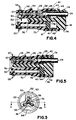
- housing 12 For accurate keying alignment with a mating connector (not shown) housing 12 includes a pair of rails 50, a latch protuberance 52 and a flat wall portion 54 (FIG. 3). Rails 50, latch protuberance 52 and flat wall portion 54 are adapted to be received in corresponding portions of the mating connector. Terminal pins or blades of the mating connector are oriented for receipt within the terminals 14. Housing 12 includes a groove 56 for receiving and retaining the mating connector seal 20.
- the mating connector seal 20 and the conductor entry seal 16 are formed of an elastomeric material and impregnated with silicon oil or similar materials.
- a plurality of outwardly extending ribs 58 and 60 are defined by the outside surface of the mating connector seal 20 and the conductor entry seal 16, respectively.
- a cleaning wiping action of any contamination or foreign materials carried by the mating connector is provided by the first inserted rib 58. Effective compression sealing is provided by the subsequent ribs 58.
- the conductor entry seal 16 has an overall size for press-fit insertion within the housing cavity 41.
- Conductor entry seal 16 includes a plurality of generally circular passageways 62 sized for interference fit engagement with the conductors 24 and a centrally located, generally D-shaped opening 64 for keying alignment with the connector cover 18.
- a plurality of outwardly extending ribs 66 are defined by an inside surface of each of the passageways 62.
- a first rib 66 provides a cleaning wiping action of any contamination carried by the inserted conductor 24 with the remaining ribs providing effective compression sealing with the inserted conductor.
- the terminal position assurance and locking cover 18 includes an axially extending elongated keying member 70, a pair of outwardly extending latching protuberances 72 received within housing apertures 46 for retaining the cover 18 in the preassembled or partly assembled condition within recess 41 of the housing 12 in the subassembly 22 (FIG. 2) and a pair of outwardly extending locking protuberances 74 received within housing apertures 48 for securing the cover 18 to the housing 12 in the final assembled condition of the sealed connector 10.
- Keying member 70 has a generally D-shape for keying alignment within D-shaped opening 64 within the conductor entry seal 16 and within the centrally located D-shaped elongated recess 38 of the housing 12. Keying member 70 includes a tapered nose portion 76 that facilitates the sliding insertion within the seal opening 64 and the housing recess 38. Keying member 70 includes a tapered base portion 78 for enhanced compression sealing with the conductor entry seal 16 as illustrated in FIG. 10.
- a plurality of spaced apart, generally circular shaped apertures 80 extend through a body portion 82 of the terminal position assurance and locking cover 18 for receiving and orienting the terminals 14.
- a plurality of radially extending ledges 84 define mating recesses 86 for receiving the housing tabs 42 and 44.
- the keying member 70 of the terminal position assurance and locking cover 18 extends through the seal opening 64 and into the housing recess 38 to align the terminal receiving apertures 80 and 62 with respective housing channels 26.
- the terminal position assurance and locking cover 18 is secured to the housing 12 in the preassembled condition by the latching protuberances 72 received within the housing apertures 46. In this condition, protuberances 74 are not in engagement with tabs 44.
- Fig. 6 illustrates the sealed connector subassembly 22 prior to the insertion of the terminals 14 with the terminated conductors 24 into the housing 12.
- the retaining arms 34 are molded to resiliently bias the locking fingers 36 of the resilient retaining arms 34 to extend within the housing recesses 26 as shown in Fig. 6.
- the locking fingers 36 of the retaining arms 34 are deflected radially inwardly as shown in Fig. 4 within the rear housing cavity 39 and in broken line in Fig. 7.
- the associated locking finger 36 moves within the terminal locking window 32 providing tactile and audible user feedback indication.
- terminal position assurance and locking cover 18 is moved into locking position as shown in Fig. 5.
- Keying member 70 engages each of the retaining arms 34 to retain the locking fingers 36 in a positively locking position in the terminal locking windows 32. If the terminals 14 are not fully inserted and/or properly positioned within the housing recesses 26, movement of the terminal position assurance and locking cover 18 into locking position is prevented.
- protuberances 72 move axially along apertures 46.
- Protuberances 74 engage tabs 44, deflect the tabs and then enter apertures 48 to lock cover 18 into place in housing 12 in the final position.
- Seal 16 is compressed in the axial direction between body 82 of cover 18 and wall 28 of housing 12 and is compressed radially by portion 78 of keying member 70. A reliable seal is made to each conductor 24, to the housing 12 and to the cover 18.
- removal of a terminal 14 is enabled by pulling the locking cover 18 outwardly to move the keying member 70 to the subassembly latching position.
- a tool (not shown) is inserted in the direction indicated by arrow labelled 90. Force is applied against the free end of the retaining arm 34 to release the locking finger 36 from the locking window 32 as indicated by an arrow labelled 92. Then the terminal 14 can be removed for repair or replacement.
- the connector 10 is simple and inexpensive to make and to assemble.
- the connector 10 is of a small size.
- the connector 10 includes terminals locking and and terminal position assurance features.
- the connector 10 has terminals 14 which can be released and replaced.
- the subassembly 22 has terminals 14 with terminated conductors which can be easily inserted without the necessity for special care or skilled labour.
- the subassembly 22 has a connector cover, a conductor entry seal and a housing mechanically secured and precisely aligned in a simple and automatic manner.
Landscapes
- Connector Housings Or Holding Contact Members (AREA)
Description
- The present invention relates to sealed connectors and more particularly to a sealed connector and sealed connector subassembly including a housing for receiving at least one terminal terminating a conductor, a conductor entry seal and a connector cover.
- Sealed connectors are known for use in environments such as automobiles for environmentally sealing the electrical connections to prevent damage from moisture and other contaminants. One example of a sealed electrical connector is disclosed in United States Patent 4,497,531 issued February 5, 1985 to Baker.
- From this document is known a sealed electrical connector comprising:
- a housing of insulating material formed with a plurality of through passageways each to receive an electrical terminal terminating an electrical conductor, each passageway extending from a mating face to an opposite, conductor-entry face of the housing;
- an axially extending shroud surrounding the conductor-entry face of the housing and defining a cavity into which the conductor-entry ends of the passageways open;
- a single sealing member receivable in the cavity and having a plurality of holes therethrough each sized to receive and grip a conductor passing through the sealing member into a respective passageway in the housing;
- a sealing member retaining lid formed with a plurality of through holes each to pass a terminal entering a respective passageway in the housing, the lid serving to close the cavity;
- the lid and the shroud being formed with cooperating latching means serving to latch the lid to the housing in the closed position.
- Disadvantages of known sealed connectors include complexity and the resulting difficulty and time required for assembly.
- It is desirable to provide a sealed connector permitting the removal of a terminal for repair or replacement. However, the construction of many prior art connectors makes it very difficult if not impossible to replace terminals without destroying the connector or the integrity of the seal. For this reason it is desirable to avoid the use of a terminal locking tang for retaining the terminal in the connector housing. However it is important to retain and securely position terminals within the connector so that a reliable electrical connection is maintained, for example, if the external terminated conductor is moved or pulled.
- Also, it is desirable to provide a unitary subassembly for receiving terminals each with a terminated conductor. Such a unitary sealed connector subassembly should be adapted for automated assembly. Many prior art sealed connectors are provided as multiple parts for assembly by the user. Hence, possible misassembly and/or contamination with foreign material or dirt prior to assembly is a problem. This problem could be solved by a unitary subassembly.
- An object of the present invention is to provide an improved sealed connector.
- Thus, in one aspect, the present invention provides a sealed connector including one or
more terminals 14 each terminating an associatedconductor 24, said sealed connector being characterised by
ahousing 12 having for each terminal a terminal receivingchannel 26 extending from aterminal entry wall 28 toward anopposed mating wall 30;
said housing having resilient arm means 34 extending within said terminal receiving channel for retaining the terminal within the terminal receiving channel;
said housing including sleeve means 40 extending axially outwardly from said terminal entry wall for defining aseal receiving cavity 41;
aconnector cover 18 having anaperture 80 or apertures one for receiving each terminal;
aseal 16 having anaperture 62 or apertures one for receiving each terminal disposed within said housingseal receiving cavity 41 between said housingterminal entry wall 28 and saidconnector cover 18;
saidconnector cover 18 including terminal position assurance means 70 co-operating with said housing terminal retaining means 34 for securing the terminal or terminals within the terminal receiving channel or channels; and
said housing and said connector cover including co-operating locking means 48, 74 for securing said connector cover to said housing. - One way of carrying out the present invention will now be described in detail by way of example with reference to drawings which show one specific embodiment.
-
- FIG. 1 is an exploded perspective view of a sealed connector constructed in accordance with the present invention and illustrating the components prior to assembly;
- FIG. 2 is a perspective view of a subassembly of the sealed connector of Figure 1 according to the present invention prior to the insertion of terminals with terminated conductors;
- FIG. 3 is an end elevational view of the subassembly taken from the line 3-3 of Figure 2;
- FIG. 4 is a sectional view taken along the line 4-4 of Figure 3 showing the terminal after the insertion of a terminal with a terminated conductor;
- FIG. 5 is a sectional view similar to Figure 4 illustrating the connector cover fully inserted in locking position;
- FIG. 6 is a sectional view taken along the line 6-6 of Figure 2;
- FIG. 7 is an enlarged, partial end view similar to the central part of Figure 3 illustrating the housing locking fingers in an initial position in broken lines and in the terminal locking position in full lines;
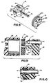
- FIG. 8 is an exploded perspective view of the connector cover and the conductor entry seal of Figure 1 prior to assembly;
- FIG. 9 is a fragmentary sectional view to illustrate the conductor entry seal relative to the connector housing and the terminated conductor; and
- FIG. 10 is a fragmentary sectional view to illustrate the conductor seal inserted within the connector housing with a terminated conductor inserted.
- Having reference now to Fig. 1, the connector 10 includes a
housing 12 for receiving and releasably securing a plurality of terminals 14 (only one being shown for clarity), aconductor entry seal 16, a terminal position assurance andlocking cover 18 and amating connector seal 20. - Referring to FIG. 2, a sealed connector subassembly generally designated as 22 of the sealed connector 10 includes the
housing 12, theconductor entry seal 16, the terminal position assurance andlocking cover 18 and therear connector seal 20 assembled together. Initially thecover 18 andhousing 12 are preassembled or partly assembled together as seen in FIGS. 2, 4 and 6. An associated conductor 24 (FIGS. 4 and 5) is terminated by each of theterminals 14 prior to insertion into the sealed connector subassembly 22. After theterminals 14 with the terminatedconductors 24 are inserted, the terminal position assurance andlocking cover 18 is moved into a locking position with thehousing 12 as shown in FIGS. 5 and 10. - Preferably, the sealed
connector housing 12 is an integral, one-piece member formed of a strong, flexible electrically insulating material. A translucent plastic or similar material forms thehousing 12 by conventional injection molding technique.Housing 12 includes a plurality of spaced-apart channels 26 extending from aterminal entry wall 28 to anopposed mating wall 30. Each of thechannels 26 has a size and shape for receiving and orienting theterminal 14. As shown in FIG. 1,channels 26 have a generally rectangular shape to orient theterminal 14 so that either one of a pair ofopposed locking windows 32 formed in eachterminal 14 is positioned within thechannel 26 facing radially inward. - Referring to FIGS. 3-7,
housing 12 is formed with a resilientretaining arm 34 outwardly extending within each of the terminal-receivingchannels 26. Eachretaining arm 34 has a freeend locking finger 36 to be received within theterminal locking window 32 for locking theterminal 14 in place in achannel 26 of thehousing 12. Referring also to FIG. 1,housing 12 includes a centrally located, generally D-shapedelongated recess 38 extending inwardly from theterminal entry wall 28 into an opposed housing cavity 39 (FIGS. 4-6) for keying and terminal position assurance features of theconnector cover 18. Theterminal receiving channels 26 are arrayed at approximately 120 degree intervals around and are spaced from the central longitudinal axis ofhousing 12 and recess 38 with the retainingarms 36 positioned for movement within thehousing cavity 39. - A
sleeve 40 of thehousing 12 extends axially outwardly from theterminal entry wall 28 defining acavity 41 for receiving theconductor entry seal 16 and theconnector cover 18.Sleeve 40 includes a plurality of spaced aparttab portions aperture connector cover 18 for securing thehousing 12 with theconnector cover 18 in thesubassembly 22 and the sealed connector 10. As seen in FIG. 1, there are two diametricallyopposed tabs 42 alternating with two diametricallyopposed tabs 44.Apertures 48 are shorter in axial length thanapertures 46. - For accurate keying alignment with a mating connector (not shown)
housing 12 includes a pair ofrails 50, alatch protuberance 52 and a flat wall portion 54 (FIG. 3).Rails 50,latch protuberance 52 andflat wall portion 54 are adapted to be received in corresponding portions of the mating connector. Terminal pins or blades of the mating connector are oriented for receipt within theterminals 14.Housing 12 includes agroove 56 for receiving and retaining themating connector seal 20. - Preferably, the
mating connector seal 20 and theconductor entry seal 16 are formed of an elastomeric material and impregnated with silicon oil or similar materials. A plurality of outwardly extendingribs mating connector seal 20 and theconductor entry seal 16, respectively. A cleaning wiping action of any contamination or foreign materials carried by the mating connector is provided by the first insertedrib 58. Effective compression sealing is provided by thesubsequent ribs 58. - Referring to FIGS. 1, 8 and 9, the
conductor entry seal 16 has an overall size for press-fit insertion within thehousing cavity 41.Conductor entry seal 16 includes a plurality of generallycircular passageways 62 sized for interference fit engagement with theconductors 24 and a centrally located, generally D-shapedopening 64 for keying alignment with theconnector cover 18. A plurality of outwardly extendingribs 66 are defined by an inside surface of each of thepassageways 62. Afirst rib 66 provides a cleaning wiping action of any contamination carried by the insertedconductor 24 with the remaining ribs providing effective compression sealing with the inserted conductor. - The terminal position assurance and locking
cover 18 includes an axially extending elongated keyingmember 70, a pair of outwardly extending latchingprotuberances 72 received withinhousing apertures 46 for retaining thecover 18 in the preassembled or partly assembled condition withinrecess 41 of thehousing 12 in the subassembly 22 (FIG. 2) and a pair of outwardly extending lockingprotuberances 74 received withinhousing apertures 48 for securing thecover 18 to thehousing 12 in the final assembled condition of the sealed connector 10. - Keying
member 70 has a generally D-shape for keying alignment within D-shapedopening 64 within theconductor entry seal 16 and within the centrally located D-shapedelongated recess 38 of thehousing 12. Keyingmember 70 includes a taperednose portion 76 that facilitates the sliding insertion within theseal opening 64 and thehousing recess 38. Keyingmember 70 includes a taperedbase portion 78 for enhanced compression sealing with theconductor entry seal 16 as illustrated in FIG. 10. - A plurality of spaced apart, generally circular shaped
apertures 80 extend through abody portion 82 of the terminal position assurance and lockingcover 18 for receiving and orienting theterminals 14. A plurality of radially extendingledges 84 definemating recesses 86 for receiving thehousing tabs - Referring to FIGS. 2 and 6, in the sealed
connector subassembly 22, the keyingmember 70 of the terminal position assurance and lockingcover 18 extends through theseal opening 64 and into thehousing recess 38 to align theterminal receiving apertures respective housing channels 26. The terminal position assurance and lockingcover 18 is secured to thehousing 12 in the preassembled condition by the latchingprotuberances 72 received within thehousing apertures 46. In this condition,protuberances 74 are not in engagement withtabs 44. - Having reference to FIGS. 4, 5, 6 and 7, the terminal position assurance feature of the connector cover is now described. Fig. 6 illustrates the sealed
connector subassembly 22 prior to the insertion of theterminals 14 with the terminatedconductors 24 into thehousing 12. The retainingarms 34 are molded to resiliently bias the lockingfingers 36 of the resilient retainingarms 34 to extend within thehousing recesses 26 as shown in Fig. 6. When theterminals 14 are inserted within thehousing recesses 26, the lockingfingers 36 of the retainingarms 34 are deflected radially inwardly as shown in Fig. 4 within therear housing cavity 39 and in broken line in Fig. 7. When each of theterminals 14 is fully inserted in thehousing recess 26, the associated lockingfinger 36 moves within theterminal locking window 32 providing tactile and audible user feedback indication. - After the
terminals 14 with the terminatedconductors 24 are fully inserted within thehousing recesses 26, the terminal position assurance and lockingcover 18 is moved into locking position as shown in Fig. 5. Keyingmember 70 engages each of the retainingarms 34 to retain the lockingfingers 36 in a positively locking position in theterminal locking windows 32. If theterminals 14 are not fully inserted and/or properly positioned within thehousing recesses 26, movement of the terminal position assurance and lockingcover 18 into locking position is prevented. - As the
cover 18 is moved from the preassembled position, protuberances 72 move axially alongapertures 46.Protuberances 74 engagetabs 44, deflect the tabs and then enterapertures 48 to lockcover 18 into place inhousing 12 in the final position.Seal 16 is compressed in the axial direction betweenbody 82 ofcover 18 andwall 28 ofhousing 12 and is compressed radially byportion 78 of keyingmember 70. A reliable seal is made to eachconductor 24, to thehousing 12 and to thecover 18. - Referring to Fig. 4, removal of a terminal 14 is enabled by pulling the locking
cover 18 outwardly to move the keyingmember 70 to the subassembly latching position. A tool (not shown) is inserted in the direction indicated by arrow labelled 90. Force is applied against the free end of the retainingarm 34 to release the lockingfinger 36 from the lockingwindow 32 as indicated by an arrow labelled 92. Then the terminal 14 can be removed for repair or replacement. - The connector 10 is simple and inexpensive to make and to assemble. The connector 10 is of a small size. The connector 10 includes terminals locking and and terminal position assurance features. The connector 10 has
terminals 14 which can be released and replaced. Thesubassembly 22 hasterminals 14 with terminated conductors which can be easily inserted without the necessity for special care or skilled labour. Thesubassembly 22 has a connector cover, a conductor entry seal and a housing mechanically secured and precisely aligned in a simple and automatic manner.
Claims (8)
- A sealed connector including one or more terminals (14) each terminating an associated conductor (24), said sealed connector comprising
a housing (12) having for each terminal a terminal receiving channel (26) extending from a terminal entry wall (28) toward an opposed mating wall (30);
said housing having resilient arm means (34) extending within said terminal receiving channel for retaining the terminal within the terminal receiving channel;
said housing including sleeve means (40) extending axially outwardly from said terminal entry wall for defining a seal receiving cavity (41);
a connector cover (18) having an aperture (80) or apertures one for receiving each terminal;
a seal (16) having an aperture (62) or apertures one for receiving each terminal disposed within said housing seal receiving cavity (41) between said housing terminal entry wall (28) and said connector cover (18);
said connector cover (18) including terminal position assurance means (70) co-operating with said housing terminal retaining means (34) for securing the terminal or terminals within the terminal receiving channel or channels; and
said housing and said connector cover including co-operating locking means (48, 74) for securing said connector cover to said housing. - A sealed connector as claimed in claim 1 wherein said connector cover terminal position assurance means (70) comprises an elongated member and said housing and said seal include corresponding passageways (38 and 64) for receiving said elongated member.
- A sealed connector as claimed in claim 2 wherein said elongated member (70) and said housing and said seal corresponding passageways (38 and 64) for receiving said elongated member are shaped for keying, whereby said terminal receiving channels (26) of said housing and said apertures of said seal and said connector cover are accurately aligned.
- A sealed connector as claimed in any preceding claim wherein said housing is adapted for releasably retaining the terminal, whereby the terminal can be removed.
- A sealed connector as claimed in claim 1, said connector cover (18), said seal (16) and said housing (12) including co-operating keying means (70, 38, 64) for keying said housing and said seal and said connector cover.
- A sealed connector as claimed in claim 5 wherein said connector cover keying means for keying said housing, said seal and said connector cover comprises an elongated D-shaped member (70) and wherein said seal and said housing co-operating keying means comprises corresponding D-shaped passageways (38 and 64) for receiving said connector cover D-shaped member.
- A sealed connector as claimed in claim 6, said housing resilient arm means (34) being disposed for engagement with said connector cover elongated D-shaped member (70) for retaining a locking finger of each arm means within a terminal locking window.
- A sealed connector as claimed in any preceding claim wherein said housing and said connector cover include co-operating latching means (46, 74) for securing said connector cover to said housing in a subassembly position.
Applications Claiming Priority (2)
| Application Number | Priority Date | Filing Date | Title |
|---|---|---|---|
| US07/130,144 US4776813A (en) | 1987-12-08 | 1987-12-08 | Sealed connector assembly |
| US130144 | 1987-12-08 |
Publications (2)
| Publication Number | Publication Date |
|---|---|
| EP0320249A1 EP0320249A1 (en) | 1989-06-14 |
| EP0320249B1 true EP0320249B1 (en) | 1993-08-04 |
Family
ID=22443272
Family Applications (1)
| Application Number | Title | Priority Date | Filing Date |
|---|---|---|---|
| EP88311608A Expired - Lifetime EP0320249B1 (en) | 1987-12-08 | 1988-12-08 | Sealed connector assembly |
Country Status (8)
| Country | Link |
|---|---|
| US (1) | US4776813A (en) |
| EP (1) | EP0320249B1 (en) |
| JP (1) | JPH07118346B2 (en) |
| KR (1) | KR970000124B1 (en) |
| BR (1) | BR8806372A (en) |
| CA (1) | CA1295026C (en) |
| DE (1) | DE3882935T2 (en) |
| ES (1) | ES2042771T3 (en) |
Cited By (1)
| Publication number | Priority date | Publication date | Assignee | Title |
|---|---|---|---|---|
| US12265266B2 (en) | 2021-09-29 | 2025-04-01 | Corning Research & Development Corporation | Fiber optic connectors having a sealing membrane disposed on the connector housing |
Families Citing this family (58)
| Publication number | Priority date | Publication date | Assignee | Title |
|---|---|---|---|---|
| JPH07101621B2 (en) * | 1987-06-16 | 1995-11-01 | 住友電装株式会社 | connector |
| US4826452A (en) * | 1987-10-16 | 1989-05-02 | Altair International, Inc. | Two-part electrical connector |
| JPH0430793Y2 (en) * | 1988-05-06 | 1992-07-24 | ||
| JPH0357027Y2 (en) * | 1988-05-06 | 1991-12-25 | ||
| JP2555394Y2 (en) * | 1988-10-26 | 1997-11-19 | 日本エー・エム・ピー 株式会社 | connector |
| GB8827756D0 (en) * | 1988-11-28 | 1988-12-29 | Amp Great Britain | Electrical connector housing assembly |
| US4900271A (en) * | 1989-02-24 | 1990-02-13 | Molex Incorporated | Electrical connector for fuel injector and terminals therefor |
| US4921437A (en) * | 1989-03-29 | 1990-05-01 | Amp Incorporated | Sealed electrical connector assembly with terminal retainer |
| US4944688A (en) * | 1989-09-25 | 1990-07-31 | Amp Incorporated | Programmable sealed connector |
| EP0424887B1 (en) * | 1989-10-24 | 1996-04-03 | The Whitaker Corporation | Electrical connector having improved secondary retention means |
| JPH0740303Y2 (en) * | 1990-03-13 | 1995-09-13 | 住友電装株式会社 | Electrical connector and connector using it |
| US5153818A (en) * | 1990-04-20 | 1992-10-06 | Rohm Co., Ltd. | Ic memory card with an anisotropic conductive rubber interconnector |
| US5044991A (en) * | 1990-11-05 | 1991-09-03 | Molex Incorporated | Electrical connector with terminal position assurance component |
| US5071369A (en) * | 1990-12-05 | 1991-12-10 | Amp Incorporated | Electrical connector having a terminal position assurance member |
| EP0529463B1 (en) * | 1991-08-28 | 1997-01-15 | The Whitaker Corporation | Seals for an electrical connector |
| JP2586314Y2 (en) * | 1991-11-08 | 1998-12-02 | 矢崎総業株式会社 | Waterproof connector |
| JP2562613Y2 (en) * | 1991-12-21 | 1998-02-16 | 住友電装株式会社 | Waterproof connector |
| JP2901111B2 (en) * | 1992-06-22 | 1999-06-07 | 矢崎総業株式会社 | Waterproof connector |
| IT1255846B (en) * | 1992-10-06 | 1995-11-17 | Amp Italia | ELECTRONIC CONNECTOR SEALED |
| US5503569A (en) * | 1993-10-04 | 1996-04-02 | The Whitaker Corporation | Electrical connector with two stage latch for retaining contacts |
| JP2911020B2 (en) * | 1994-03-28 | 1999-06-23 | 矢崎総業株式会社 | Electrical connection terminal |
| JP2957084B2 (en) * | 1994-04-08 | 1999-10-04 | 矢崎総業株式会社 | Connector housing |
| JPH0864315A (en) * | 1994-08-02 | 1996-03-08 | Molex Inc | Receptacle type electricity connector |
| JP3109794B2 (en) * | 1994-09-27 | 2000-11-20 | ヒロセ電機株式会社 | Waterproof connector |
| DE19532381C2 (en) * | 1995-09-01 | 1999-11-11 | Siemens Ag | Electrical connector with contact locking slide |
| US5730624A (en) * | 1995-11-30 | 1998-03-24 | Itt Corporation | Secondary contact lock arrangement |
| US5716233A (en) * | 1995-11-30 | 1998-02-10 | Itt Corporation | Contact position assurance device |
| DE29704689U1 (en) * | 1997-03-14 | 1997-05-15 | Intercontec GmbH, 94336 Hunderdorf | Contact carrier for electrical multiple connectors |
| FR2764128B1 (en) * | 1997-05-29 | 2002-11-29 | Proner Comatel Sa | SECONDARY LOCK FOR ELECTRICAL CONNECTOR |
| JP3566541B2 (en) * | 1998-03-31 | 2004-09-15 | 矢崎総業株式会社 | Waterproof connector and waterproofing method |
| JP3566540B2 (en) * | 1998-03-31 | 2004-09-15 | 矢崎総業株式会社 | Waterproof connector |
| JP3517109B2 (en) | 1998-03-31 | 2004-04-05 | 矢崎総業株式会社 | Waterproof connector and method of assembling waterproof connector |
| JP3547988B2 (en) | 1998-03-31 | 2004-07-28 | 矢崎総業株式会社 | Waterproof connector and waterproofing method |
| JPH11354201A (en) | 1998-06-10 | 1999-12-24 | Yazaki Corp | Waterproof connector |
| JP3500065B2 (en) | 1998-06-25 | 2004-02-23 | 矢崎総業株式会社 | Waterproof connector |
| JP3540164B2 (en) | 1998-07-06 | 2004-07-07 | 矢崎総業株式会社 | Waterproof connector |
| JP3691291B2 (en) * | 1999-06-28 | 2005-09-07 | 矢崎総業株式会社 | Waterproof connector |
| US6409541B1 (en) * | 2000-11-02 | 2002-06-25 | Autonetworks Technologies, Ltd. | Waterproof structure in cable insertion section, method of manufacturing the same, and die for waterproof molding |
| JP3804483B2 (en) * | 2001-05-18 | 2006-08-02 | 住友電装株式会社 | Waterproof connector |
| JP3767460B2 (en) | 2001-11-05 | 2006-04-19 | 住友電装株式会社 | Waterproof connector |
| US7077701B2 (en) * | 2003-06-06 | 2006-07-18 | Tyco Electronics Corporation | Sealed electrical connector |
| US20050173098A1 (en) * | 2003-06-10 | 2005-08-11 | Connors Matthew J. | Three dimensional vapor chamber |
| US20050139995A1 (en) * | 2003-06-10 | 2005-06-30 | David Sarraf | CTE-matched heat pipe |
| DE102004053576B3 (en) * | 2004-11-05 | 2006-04-13 | Lisa Dräxlmaier GmbH | Knob for fitting on gear shift rod of vehicle has means of locking formed on sleeve-form clamping element and consisting of several locking hooks formed on clamping element and spaced by cut-outs |
| US7097486B2 (en) * | 2005-02-03 | 2006-08-29 | Cushcraft Corporation | Low-cost weatherproof cable feedthrough |
| RU2319264C1 (en) * | 2007-01-09 | 2008-03-10 | Сергей Евгеньевич Варламов | Electrical connector and method for its manufacture |
| US7473113B2 (en) * | 2007-03-31 | 2009-01-06 | Kojiro Koda | Electrical connection for high humidity and low temperature environments |
| AT505774B1 (en) * | 2007-11-15 | 2009-04-15 | Sterner Franz | HOUSING FOR RECEIVING CABLE END |
| JP5417954B2 (en) * | 2009-04-09 | 2014-02-19 | 住友電装株式会社 | Waterproof connector |
| JP2011198566A (en) * | 2010-03-18 | 2011-10-06 | Sumitomo Wiring Syst Ltd | Charging connector |
| JP2012221797A (en) * | 2011-04-11 | 2012-11-12 | Iriso Electronics Co Ltd | Connector |
| US8425244B2 (en) * | 2011-07-26 | 2013-04-23 | Motorola Solutions, Inc. | Connector with a locking sleeve for locking to a socket having a circular band |
| JP5970171B2 (en) * | 2011-11-08 | 2016-08-17 | 富士電線工業株式会社 | Manufacturing method of cord with plug |
| US8974241B2 (en) | 2013-01-28 | 2015-03-10 | Itt Manufacturing Enterprises, Llc | Bracket for connector pin seals |
| JP6604512B2 (en) * | 2016-02-24 | 2019-11-13 | 住友電装株式会社 | connector |
| DE102018118774B4 (en) * | 2018-08-02 | 2022-07-14 | Harting Electric Gmbh & Co. Kg | Modular connector system |
| JP6964105B2 (en) * | 2019-03-14 | 2021-11-10 | ヒロセ電機株式会社 | Connector and how to assemble the connector |
| TWM629291U (en) | 2021-07-07 | 2022-07-11 | 大陸商富加宜電子(南通)有限公司 | Hybrid connector |
Family Cites Families (8)
| Publication number | Priority date | Publication date | Assignee | Title |
|---|---|---|---|---|
| US3937545A (en) * | 1974-12-23 | 1976-02-10 | Ford Motor Company | Waterproof electrical connector |
| US4364621A (en) * | 1980-02-28 | 1982-12-21 | General Signal Corp. | Electrical connector |
| DE3268266D1 (en) * | 1981-07-23 | 1986-02-13 | Amp Inc | Sealed electrical connector |
| JPS5921510Y2 (en) * | 1982-03-19 | 1984-06-25 | 矢崎総業株式会社 | waterproof connector |
| JPS60249273A (en) * | 1984-05-23 | 1985-12-09 | 日産自動車株式会社 | Mounting structure of connecting terminal |
| GB8615420D0 (en) * | 1986-06-24 | 1986-07-30 | Amp Gmbh | Electrical connector |
| US4714437A (en) * | 1987-01-20 | 1987-12-22 | Ford Motor Company | Electrical connector |
| US4740177A (en) * | 1987-02-09 | 1988-04-26 | Standex International Corporation | Cluster assembly with locking tabs |
-
1987
- 1987-12-08 US US07/130,144 patent/US4776813A/en not_active Expired - Lifetime
-
1988
- 1988-11-14 CA CA000582939A patent/CA1295026C/en not_active Expired - Lifetime
- 1988-12-02 BR BR888806372A patent/BR8806372A/en unknown
- 1988-12-07 KR KR1019880016239A patent/KR970000124B1/en not_active Expired - Fee Related
- 1988-12-07 JP JP63309782A patent/JPH07118346B2/en not_active Expired - Lifetime
- 1988-12-08 ES ES88311608T patent/ES2042771T3/en not_active Expired - Lifetime
- 1988-12-08 DE DE88311608T patent/DE3882935T2/en not_active Expired - Fee Related
- 1988-12-08 EP EP88311608A patent/EP0320249B1/en not_active Expired - Lifetime
Cited By (1)
| Publication number | Priority date | Publication date | Assignee | Title |
|---|---|---|---|---|
| US12265266B2 (en) | 2021-09-29 | 2025-04-01 | Corning Research & Development Corporation | Fiber optic connectors having a sealing membrane disposed on the connector housing |
Also Published As
| Publication number | Publication date |
|---|---|
| JPH01187783A (en) | 1989-07-27 |
| KR890011147A (en) | 1989-08-12 |
| CA1295026C (en) | 1992-01-28 |
| KR970000124B1 (en) | 1997-01-04 |
| DE3882935T2 (en) | 1994-01-13 |
| DE3882935D1 (en) | 1993-09-09 |
| ES2042771T3 (en) | 1993-12-16 |
| US4776813A (en) | 1988-10-11 |
| EP0320249A1 (en) | 1989-06-14 |
| BR8806372A (en) | 1989-08-22 |
| JPH07118346B2 (en) | 1995-12-18 |
Similar Documents
| Publication | Publication Date | Title |
|---|---|---|
| EP0320249B1 (en) | Sealed connector assembly | |
| KR100190793B1 (en) | Electrical connector | |
| EP0585791B1 (en) | Panel mountable electrical connector | |
| EP0306635B1 (en) | Electrical connector | |
| US4588242A (en) | Sealed electrical connector | |
| EP0585633A1 (en) | Latchable electrical connector system | |
| US5967859A (en) | Electrical connector assembly with terminal retainer system | |
| US5435738A (en) | Lever-type connector | |
| US5328382A (en) | Electrical connector with external seal and internal terminal retaining means | |
| US6059594A (en) | Sealed electrical connector | |
| EP0125786A2 (en) | Electrical connector assembly | |
| EP0035378B1 (en) | Electrical connector | |
| US5181865A (en) | Electrical connector with secondary locking | |
| EP0665453B1 (en) | Electrical connector assembly | |
| KR100326219B1 (en) | Electrical connector with terminal position assurance device | |
| US5651704A (en) | Electrical connector with terminal retainer | |
| US5352133A (en) | Connector assembly having anti-overstress latch means | |
| US4717359A (en) | Arrangement for securing electrical terminal in terminal holder | |
| EP0877447B1 (en) | Connector | |
| KR100313129B1 (en) | Peel Key and Latch Assembly | |
| EP0788670B1 (en) | Sealable connector assembly having secondary lock | |
| EP0510583B1 (en) | Electric connector | |
| EP1206014B1 (en) | Panel attachment configuration for a connector | |
| EP0581320B1 (en) | Electric connector | |
| US4726792A (en) | Electrical connector having electrical contacts provided with retention means |
Legal Events
| Date | Code | Title | Description |
|---|---|---|---|
| PUAI | Public reference made under article 153(3) epc to a published international application that has entered the european phase |
Free format text: ORIGINAL CODE: 0009012 |
|
| AK | Designated contracting states |
Kind code of ref document: A1 Designated state(s): DE ES FR GB IT SE |
|
| 17P | Request for examination filed |
Effective date: 19891125 |
|
| 17Q | First examination report despatched |
Effective date: 19920123 |
|
| GRAA | (expected) grant |
Free format text: ORIGINAL CODE: 0009210 |
|
| AK | Designated contracting states |
Kind code of ref document: B1 Designated state(s): DE ES FR GB IT SE |
|
| ITF | It: translation for a ep patent filed | ||
| REF | Corresponds to: |
Ref document number: 3882935 Country of ref document: DE Date of ref document: 19930909 |
|
| ET | Fr: translation filed | ||
| REG | Reference to a national code |
Ref country code: ES Ref legal event code: FG2A Ref document number: 2042771 Country of ref document: ES Kind code of ref document: T3 |
|
| PLBE | No opposition filed within time limit |
Free format text: ORIGINAL CODE: 0009261 |
|
| STAA | Information on the status of an ep patent application or granted ep patent |
Free format text: STATUS: NO OPPOSITION FILED WITHIN TIME LIMIT |
|
| 26N | No opposition filed | ||
| EAL | Se: european patent in force in sweden |
Ref document number: 88311608.9 |
|
| PGFP | Annual fee paid to national office [announced via postgrant information from national office to epo] |
Ref country code: GB Payment date: 20001107 Year of fee payment: 13 |
|
| PGFP | Annual fee paid to national office [announced via postgrant information from national office to epo] |
Ref country code: SE Payment date: 20001201 Year of fee payment: 13 |
|
| PGFP | Annual fee paid to national office [announced via postgrant information from national office to epo] |
Ref country code: FR Payment date: 20001204 Year of fee payment: 13 |
|
| PGFP | Annual fee paid to national office [announced via postgrant information from national office to epo] |
Ref country code: ES Payment date: 20001219 Year of fee payment: 13 |
|
| PGFP | Annual fee paid to national office [announced via postgrant information from national office to epo] |
Ref country code: DE Payment date: 20001222 Year of fee payment: 13 |
|
| PG25 | Lapsed in a contracting state [announced via postgrant information from national office to epo] |
Ref country code: GB Free format text: LAPSE BECAUSE OF NON-PAYMENT OF DUE FEES Effective date: 20011208 |
|
| PG25 | Lapsed in a contracting state [announced via postgrant information from national office to epo] |
Ref country code: SE Free format text: LAPSE BECAUSE OF NON-PAYMENT OF DUE FEES Effective date: 20011209 |
|
| REG | Reference to a national code |
Ref country code: GB Ref legal event code: IF02 |
|
| PG25 | Lapsed in a contracting state [announced via postgrant information from national office to epo] |
Ref country code: DE Free format text: LAPSE BECAUSE OF NON-PAYMENT OF DUE FEES Effective date: 20020702 |
|
| EUG | Se: european patent has lapsed |
Ref document number: 88311608.9 |
|
| GBPC | Gb: european patent ceased through non-payment of renewal fee |
Effective date: 20011208 |
|
| PG25 | Lapsed in a contracting state [announced via postgrant information from national office to epo] |
Ref country code: FR Free format text: LAPSE BECAUSE OF NON-PAYMENT OF DUE FEES Effective date: 20020830 |
|
| REG | Reference to a national code |
Ref country code: FR Ref legal event code: ST |
|
| PG25 | Lapsed in a contracting state [announced via postgrant information from national office to epo] |
Ref country code: ES Free format text: LAPSE BECAUSE OF NON-PAYMENT OF DUE FEES Effective date: 20021209 |
|
| REG | Reference to a national code |
Ref country code: ES Ref legal event code: FD2A Effective date: 20030113 |
|
| PG25 | Lapsed in a contracting state [announced via postgrant information from national office to epo] |
Ref country code: IT Free format text: LAPSE BECAUSE OF NON-PAYMENT OF DUE FEES Effective date: 20051208 |