EP4531071A2 - X-ray tube anode with optimized area focal spot track - Google Patents
X-ray tube anode with optimized area focal spot track Download PDFInfo
- Publication number
- EP4531071A2 EP4531071A2 EP24195067.4A EP24195067A EP4531071A2 EP 4531071 A2 EP4531071 A2 EP 4531071A2 EP 24195067 A EP24195067 A EP 24195067A EP 4531071 A2 EP4531071 A2 EP 4531071A2
- Authority
- EP
- European Patent Office
- Prior art keywords
- anode
- track
- emissive material
- width
- focal spot
- Prior art date
- Legal status (The legal status is an assumption and is not a legal conclusion. Google has not performed a legal analysis and makes no representation as to the accuracy of the status listed.)
- Pending
Links
Images




Classifications
-
- H—ELECTRICITY
- H01—ELECTRIC ELEMENTS
- H01J—ELECTRIC DISCHARGE TUBES OR DISCHARGE LAMPS
- H01J35/00—X-ray tubes
- H01J35/02—Details
- H01J35/04—Electrodes ; Mutual position thereof; Constructional adaptations therefor
- H01J35/08—Anodes; Anti cathodes
- H01J35/10—Rotary anodes; Arrangements for rotating anodes; Cooling rotary anodes
-
- H—ELECTRICITY
- H01—ELECTRIC ELEMENTS
- H01J—ELECTRIC DISCHARGE TUBES OR DISCHARGE LAMPS
- H01J35/00—X-ray tubes
- H01J35/02—Details
- H01J35/04—Electrodes ; Mutual position thereof; Constructional adaptations therefor
- H01J35/06—Cathodes
- H01J35/065—Field emission, photo emission or secondary emission cathodes
-
- H—ELECTRICITY
- H01—ELECTRIC ELEMENTS
- H01J—ELECTRIC DISCHARGE TUBES OR DISCHARGE LAMPS
- H01J35/00—X-ray tubes
- H01J35/02—Details
- H01J35/04—Electrodes ; Mutual position thereof; Constructional adaptations therefor
- H01J35/08—Anodes; Anti cathodes
- H01J35/10—Rotary anodes; Arrangements for rotating anodes; Cooling rotary anodes
- H01J35/108—Substrates for and bonding of emissive target, e.g. composite structures
-
- H—ELECTRICITY
- H01—ELECTRIC ELEMENTS
- H01J—ELECTRIC DISCHARGE TUBES OR DISCHARGE LAMPS
- H01J35/00—X-ray tubes
- H01J35/02—Details
- H01J35/16—Vessels; Containers; Shields associated therewith
-
- H—ELECTRICITY
- H01—ELECTRIC ELEMENTS
- H01J—ELECTRIC DISCHARGE TUBES OR DISCHARGE LAMPS
- H01J35/00—X-ray tubes
- H01J35/24—Tubes wherein the point of impact of the cathode ray on the anode or anticathode is movable relative to the surface thereof
- H01J35/26—Tubes wherein the point of impact of the cathode ray on the anode or anticathode is movable relative to the surface thereof by rotation of the anode or anticathode
-
- H—ELECTRICITY
- H01—ELECTRIC ELEMENTS
- H01J—ELECTRIC DISCHARGE TUBES OR DISCHARGE LAMPS
- H01J2235/00—X-ray tubes
- H01J2235/08—Targets (anodes) and X-ray converters
- H01J2235/081—Target material
-
- H—ELECTRICITY
- H01—ELECTRIC ELEMENTS
- H01J—ELECTRIC DISCHARGE TUBES OR DISCHARGE LAMPS
- H01J2235/00—X-ray tubes
- H01J2235/08—Targets (anodes) and X-ray converters
- H01J2235/083—Bonding or fixing with the support or substrate
- H01J2235/084—Target-substrate interlayers or structures, e.g. to control or prevent diffusion or improve adhesion
-
- H—ELECTRICITY
- H01—ELECTRIC ELEMENTS
- H01J—ELECTRIC DISCHARGE TUBES OR DISCHARGE LAMPS
- H01J2235/00—X-ray tubes
- H01J2235/08—Targets (anodes) and X-ray converters
- H01J2235/086—Target geometry
-
- H—ELECTRICITY
- H01—ELECTRIC ELEMENTS
- H01J—ELECTRIC DISCHARGE TUBES OR DISCHARGE LAMPS
- H01J2235/00—X-ray tubes
- H01J2235/12—Cooling
- H01J2235/1225—Cooling characterised by method
- H01J2235/1291—Thermal conductivity
Definitions
- FIG. 6 illustrates a cross-sectional view of an X-ray source 12 incorporating embodiments of the invention.
- X-ray source 12 is an X-ray tube 40 that includes an anode assembly 42 and a cathode assembly 44.
- the anode and cathode assemblies 42, 44 are supported within an insert or frame 46, which houses a target or anode 48, a bearing assembly 50, and a cathode 52.
- Frame 46 defines an area of y low pressure (e.g., a vacuum) compared to ambient, in which high voltages may be present.
- Frame 46 may be positioned within a casing (not shown) filled with a cooling medium, such as oil, that may also provide high voltage insulation. While the target and anode are described above as being a common component of X-ray tube 40, the target and anode may be separate components in alternative X-ray tube embodiments.
- an electron beam 54 is produced by cathode assembly 44.
- cathode 52 receives one or more electrical signals via a plurality of electrical leads 56.
- the electrical signals may include power and timing/control signals that cause cathode 52 to emit electron beam 54 at one or more energies and at one or more frequencies.
- the electrical signals may also at least partially control the potential between cathode 52 and anode 48.
- Cathode 52 includes an insulator 58 from which an arm 60 extends. Arm 60 encloses electrical leads 56, which extend into a cathode cup 62 mounted at the end of arm 60.
- cathode cup 62 includes focusing elements that focuses electrons emitted from a filament within cathode cup 62 to form electron beam 54.
- X-rays 64 are produced when high-speed electrons of electron beam 54 from cathode 52 are suddenly decelerated upon impacting a focal spot/target surface 66 formed on anode target 48.
- the high-speed electrons forming electron beam 54 are accelerated toward the anode target 48 via a potential difference therebetween of, for example, twenty (20) to one hundred and sixty (160) kV for medical diagnostic imaging , including sixty (60) kV or more in the case of CT applications.
- the X-rays 64 are emitted through a radiation emission window 68 formed in frame 46 that is positioned toward a detector array, such as detector 18 of FIG. 5 .
- the anode 48 On a target surface 66 of the body 100 that is positioned to face the cathode 54 within the path of the electron beam 52 remitted from the cathode 54, the anode 48 includes an emissive material track 104 disposed thereon.
- the emissive material track 104 is formed of a suitably emissive material, including but not limited to tungsten and/or rhodium.
- the difference between a first atomic number Z 1 of the material forming the emissive material track 104 and a second atomic number Z 2 of the relatively non-emissive material forming the body 100, or any other material 103 that is disposed on the surface 101 between the emissive material track 104 and the body 100 that is different than the material forming the body 100 should be at least 3% or more, or in another exemplary embodiment at least 7% or more, with the material forming the emissive material track 104 being higher in each case.
- the ratio between the first atomic number Z 1 of the material forming the emissive material track 104 and the second atomic number Z 2 of the relatively non-emissive material forming the body 100, or any other material 103 that is disposed on the surface 101 between the emissive material track 104 and the body 100 that is different than the material forming the body 100 can be at least greater than 6, and in another exemplary embodiment is at least greater than 12, again with the material forming the emissive material track 104 being higher in each case.
- the relatively non-emissive material forming the body 100 or material 103 is molybdenum, molybdenum alloy, or carbon, and the emissive material track 104 is formed from rhodium or tungsten alloy.
- the emissive material track 104 is positioned on the body 100 to cover and/or encompass the focal spot track 106 followed by the focal spot 107 to be struck by the electron beam 52 as it moves due to rotation of the anode 48 during the operation of the X-ray source 40.
- the emissive material track 104 can be attached to the body 100 in any suitable manner, such as by welding or brazing the emissive material track 104 to the body 100, or by depositing material forming the emissive material track 104 directly onto the body 100 in a suitable manner to form the emissive material track 104.
- the emissive material track 104 has a planar, generally circular ring shape to extend round the body 100 along the entire path of the focal spot track 106, i.e., the track or path of the focal spot/target surface 66 along the anode 48 as the anode is rotated during operation of the X-ray tube 12, during rotation of the anode 48, with an inner diameter ring 108 and an outer diameter ring 110.
- the first width or width W 1 of the emissive material track 104 between the inner ring 108 and the outer ring 110 is larger than the second width or width W 2 of the focal spot track 106, as defined by the length L 1 of the focal spot 107 defining the focal spot track 106, such that the entire focal spot track 106 can be encompassed within the width W 1 emissive material track 104.
- the width W 1 of the emissive material track 104 is significantly less than the radius R of the body 100 from the shaft 76 or sleeve 78 secured to the body 100 to a peripheral edge 115 of the body.
- the cathode 52 is operated to emit the electron beam 54 to strike the rotating anode 48 along focal spot track 106 to cause the emissive material track 104 to emit X-rays 120 within the focal spot track 106 overlapping the emissive material track 104.
- some of the electrons 122 within the electron beam 54 striking the emissive material track 104 can bounce or rebound off of the emissive material track 104, with some of these rebounding electrons 122 attracted back towards the anode 48.
- rebounding electrons 122 pass beyond the width W 1 of the emissive material track 104 and instead strike the body 100 formed of the suitably non-emissive substrate material to either side of the emissive material track 104.
- the focal spot track 106 is centered within the emissive material track 104.
- the emissive material track 104 extends outwardly to each side of the focal spot track 106 a distance of approximately one quarter of the width W 2 of the focal spot track 106.
- an anode 148 includes a body 150 defining a peripheral surface 151 towards which an electron beam 54 is directed and formed of a suitable, or relatively non-emissive substrate material, similar or identical to the material forming body 100, and a shaft 152 operably connected to the body 150 and extending outwardly therefrom for attachment within a compatible X-ray source (not shown).
- the body 150 can be formed to have any of a multitude of suitable configurations, such as a body 150 that is conic in shape, with one or more angles between the cone of the body 150 and the axis defined by the shaft 152. In the exemplary illustrated embodiments of FIG.
- the body 150 is formed with a cylindrical shape, with the shaft 152 operably connected along a central axis of the body 150, and includes a pair of emissive material tracks 154,156 formed of materials similar to that of emissive material track 104 and disposed around the perimeter of the body 150. Further, the percentage difference and/or that rations for the first and second atomic numbers of the materials forming the body 150 and the emissive material tracks 154,156 can be the same as described previously with regard to body 100 and emissive material track 104.
- the emissive material tracks 154,156 can be spaced from one another, exposing one or more portions of the body 150, or any other material 153 that is disposed on the surface 151 between the emissive material tracks 154,156 and the body 150 that is different than the material forming the body 150, between the pair of emissive material tracks 154,156..
- the emissive material tracks 154,156 can be formed of the same type of emissive material, or can be formed from different types of emissive materials, such as chromium, aluminum, ytrrium, zirconium, magnesium, silicon, silver, titanium, molybdenum, rhodium and tungsten. Alternatively, as shown in FIG.
- the tracks 154,156 can be formed from a unitary layer 155 of emissive material having a blocking strip 157 of a lower X-ray emission capability material, i.e., low atomic number Z, disposed thereon, similar to body 150, thereby separating the unitary layer 155 into the emissive material tracks 154,156.
- the emissive material tracks 154,156 each have a different width, W 3 for track 154 and W 4 for track 156, such that the tracks 154 and 156 accommodate focal spot tracks 158,160 having different widths, i.e., W 5 for focal spot track 158 and W 6 for focal spot track 160 corresponding to the lengths L 2 and L 3 of the focal spots 107 defining each focal spot track 158,160, and that are each less than the width W 7 of the surface 151 of the body 150.
- the widths W 3 and W 4 of the emissive material tracks 154,156 each conform to the widths W 5 and W 6 for the focal spot tracks 158,160 according to the parameters of one or more of the embodiments discussed previously with regard to the anode 48 and the emissive material track 104 and focal spot track 106 disposed thereon.
- the single anode 148 can be employed for use in imaging procedures requiring different focal lengths, as the electron beam 54 can be directed onto the desired focal spot 107 and associated focal spot track(s) 158,160 and emissive material track(s) 154,156 to provide the improvements to the operation of the anode 148 provided by the emissive material tracks 154,156 as discussed previously.
- the anode 48 can be formed with a body 100 formed of an emissive material, i.e., with a high atomic number Z 1 , similar to that used for the emissive material tracks 104,154,156, such as that described previously.
- a blocking cover 162 formed of a low x-ray emission material as used with prior embodiments for the body 100 shown in FIGS.
- the cover 162 can be deposited in any suitable manner on the areas of the body 100 outside of the focal spot track(s) 106,158,160, with the material forming the cover 162 having suitable non-emission properties and a thickness of between 10 ⁇ m-100 ⁇ m, in one exemplary embodiment.
- the material forming the thermally conductive cover 164 such as a carbon material, e.g., carbon in diamond form, is capable of having the emissive material track(s) 104,154,156 deposited directly thereon over the area(s) of the body 100 and the cover 164 defining and/or aligned with the focal spot track(s) 106,158,160.
- a carbon material e.g., carbon in diamond form
- the thermally conductive cover 164 effectively prevents or limits the potential for rebounding electrons 122 to strike the body 100 outside of the emissive material track(s) 104,154,156 defining the focal spot track(s) 106,158,160, while also improving heat conductivity from the emissive material track(s) 104,154,156 defining the focal spot track(s) 106,158,160 to the remainder of the thermally conductive cover 164 and body 100 due to the improved thermal conductivity properties of the material forming the thermally conductive cover 164.
Landscapes
- X-Ray Techniques (AREA)
- Apparatus For Radiation Diagnosis (AREA)
Abstract
Description
- The invention relates generally to X-ray tubes and, more particularly, to structures and methods of construction for the anode utilized in an X-ray tube.
- X-ray systems, including computed tomography (CT) imaging systems, may include an X-ray tube, a detector, and a support structure for the X-ray tube and the detector. In operation, an imaging table, on which an object is positioned, may be located between the X-ray tube and the detector. The X-ray tube typically emits radiation, such as X-rays, toward the object. The radiation passes through the object on the imaging table and impinges on the detector. As radiation passes through the object, internal structures of the object cause spatial variances in the radiation received at the detector. The detector then generates data, and the system translates the data into an image, which may be used to evaluate the internal structures of the object. The object may include, but is not limited to, a patient in a medical imaging procedure or an inanimate object as in, for instance, a package.
- X-ray tubes include a cathode and an anode having an anode target located within a high-vacuum environment. The anode is disposed in front of the cathode so that the focused electron beam from the cathode is accelerated across a cathode-to-anode vacuum gap and produces X-rays upon impact with the focal spot on the anode target. Electrons from the cathode hit successively different points of the anode target to reduce the maximum temperature reached locally by the anode target. In many configurations the anode is a circular material piece supported by a bearing structure to enable the anode to rotate in front of the cathode. Because of the high temperatures generated when the electron beam strikes the anode target, it is often necessary to rotate the anode assembly at a high rotational speed, causing the focal spot to be directed onto the rotating anode target along a focal spot track defined by the path of the focal spot along the rotating anode target, where the length L of the focal spot defines the width W of the focal spot track extending around the perimeter of the anode target.
- As shown in
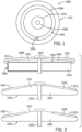
FIGS. 1 and 2 , the construction of aprior art anode 1000 typically includes acentral shaft 1002 to which is secured a disc- or drum-shaped support member 1004. Thesupport member 1004 is formed of asupport material 1006 that constitutes the majority of the mass and volume of theanode 1000 and that has the desired properties with respect to emission of X-rays, i.e., thesupport material 1006 is a relatively non-emissive material that does not readily emit X-rays when struck by the electrons/electron beam from the cathode. - When a
larger anode 1000 is desired to further increase the instant peak power on focal spot, due to weight considerations for a rotatinganode 1000, theanode 1000 is made of two or more materials. In particular, the material forming thesupport member 1004 can be selected to be a lighter material than if thesupport member 1004 were designed to directly emit X-rays. In order to emit X-rays from theanode 1000, thesupport member 1004 is coated with a layer of anemission material 1008 having properties suitable for the emission of X-rays when struck by the beam of electrons from the cathode. The layer of electronemissive material 1008 has width between anouter diameter 1011 and aninner diameter 1013 of thesupport member 1004 of between 70mm and 200mm, such that theemissive material layer 1008 is disposed substantially over theentire surface 1010 of thesupport member 1004 that faces or positioned towards the cathode and the electron beam generated by the cathode. The electron beam is directed by the cathode onto afocal spot 1015 that is projected along afocal spot track 1012 on the layer ofemissive material 1008 as theanode 1000 is rotated in order to direct the X-ray emitted from the emission material towards the desired area of the object being imaged and the detector. The size of thefocal spot track 1012 can vary depending upon type or modality of imaging being performed by the X-ray tube including theanode 1000, as illustrated on thedrum anode 1014 shown inFIG. 3 including a longerfocal spot track 1016 and a shorterfocal spot track 1018, each of which correspond in width W to the length L of the associatedfocal spot 1015 for eachtrack focal spot track emissive material 1008 to be emitted onto the desired area of the object and detector. - While many of the
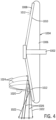
electrons 1020 in the electron beam striking theemissive material layer 1008 cause the emissive material to emitX-rays 1022 within thefocal spot track 1012,other electrons 1024 striking theemissive material layer 1008 can bounce or rebound off of theemissive material layer 1008, as shown inFIG. 4 . Some of these reboundingelectrons 1024 can be attracted back towards theanode 1000 to strike theemissive material layer 1008 outside of thefocal spot track 1012, as the width of theemissive material layer 1008, i.e., 120mm-150mm, greatly exceeds the width of thefocal spot track 1012, e.g., 0.10mm-10.0mm. When the reboundingelectrons 1024 strike theemissive material layer 1008 again outside of thefocal spot track 1012, they can also causeX-rays 1026 to be emitted from theemissive material layer 1008. However, as theseX-rays 1026 emitted are not within thefocal spot track X-rays 1026 created by the reboundingelectrons 1024 form off-focus radiation that is directed towards the object being imaged and the detector. This off-focus radiation can significantly degrade the sharpness and overall image quality of the image produced by the detector from the X-rays passing through the object prior to reaching the detector. - Therefore, it is desirable to develop an improved anode structure that significantly limits the generation of off focus radiation and that can significantly reduce the material costs associated with the construction of the anode.
- In one exemplary embodiment of the invention, an anode for an X-ray tube has a rotating component, a body operably connected to the rotating component and adapted to rotate in conjunction with the rotating component, and at least one emissive material track defined on the body wherein the at least one emissive material track has a first width, and wherein the first width is less than or equal to twice a second width of a focal spot track on the body.
- In another exemplary embodiment of the invention, an X-ray tube has a cathode assembly, and an anode assembly spaced from the cathode assembly, wherein the anode assembly includes a shaft, a sleeve disposed on the shaft, wherein one of the shaft and the sleeve is rotatable with regard to the other to form a rotating component and a stationary component, a body attached to the rotating component, and at least one emissive material track disposed on the body, wherein the at least one emissive material track has a first width, wherein the first width is less than or equal to twice a second width of a focal spot track on the body.
- In still another exemplary embodiment of the disclosure, a method for minimizing off focus radiation generated in an imaging procedure using an X-ray tube includes the steps of providing an X-ray tube having a cathode assembly, and an anode assembly spaced from the cathode assembly, wherein the anode assembly includes a shaft, a sleeve disposed on the shaft, wherein one of the shaft and the sleeve is rotatable with regard to the other to form a rotating component and a stationary component, a body attached to the rotating component; and at least one emissive material track defined on the body, wherein the at least one emissive material track has a first width, and wherein the first width is less than or equal to twice a second width of a focal spot track on the body, directing the electron beam from the cathode assembly onto at least one the emissive material track along the focal spot track, and enabling electrons from the electron beam bouncing off of the emissive material track to contact the body on either side of the at least one emissive material track, wherein the emissive material track is formed of a material having a first atomic number and wherein the body is formed of a material having a second atomic number and wherein a ratio of the first atomic number to the second atomic number is at least 6.
- It should be understood that the brief description above is provided to introduce in simplified form a selection of concepts that are further described in the detailed description. It is not meant to identify key or essential features of the claimed subject matter, the scope of which is defined uniquely by the claims that follow the detailed description. Furthermore, the claimed subject matter is not limited to implementations that solve any disadvantages noted above or in any part of this disclosure.
-
-
FIG. 1 is a top plan view of a prior anode structure of an X-ray tube. -
FIG. 2 illustrates different anode constructions of a prior art anode including an emissive material layer. -
FIG. 3 is a side elevational view of a prior art drum anode structure of an X-ray tube. -
FIG. 4 is a schematic view of the creation of off-focus radiation from electrons bouncing off of a focal spot track on the prior art anode ofFIG. 1 . -
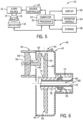
FIG. 5 is a block diagram of an imaging system incorporating exemplary embodiments of the disclosure. -
FIG. 6 is a cross-sectional view of a portion of an X-ray tube according to an exemplary embodiment of the disclosure. -
FIG. 7 is a top plan view of a first embodiment of an anode structure employed within the X-ray tube ofFIG. 6 , according to an exemplary embodiment of the disclosure. -
FIG. 8 are cross-sectional views of different anode construction embodiments for the anode ofFIG. 7 with a single focal spot track, according to an embodiment of the disclosure. -
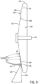
FIG. 9 is a schematic view of the elimination of off-focus radiation from electrons bouncing off of a focal spot track provided by the anode ofFIG. 7 according to an exemplary embodiment of the disclosure. -
FIGS. 10A and 10B are comparisons of the emissive material layers on a prior art anode ofFIG. 1 and the anode ofFIG. 7 in comparison with a focal spot track of equal size, according to an exemplary embodiment of the disclosure. -
FIG. 11 is a side elevational view of a second embodiment of an anode structure according to an exemplary embodiment of the disclosure. -
FIG. 12 is a side elevational view of a third embodiment of an anode structure according to an exemplary embodiment of the disclosure. -
FIG. 13 is a cross-sectional view of the anode ofFIG. 7 with a single focal spot track, according to another exemplary embodiment of the disclosure. -
FIG. 14 is a cross-sectional view of the anode ofFIG. 7 with a single focal spot track, according to a further exemplary embodiment of the disclosure. -
FIG. 5 is a block diagram of an embodiment of animaging system 10 designed both to acquire original image data and to process the image data for display and/or analysis in accordance with embodiments of the invention. It will be appreciated by those skilled in the art that various embodiments of the invention are applicable to numerous medical imaging systems implementing an X-ray tube, such as X-ray imaging systems or fluoroscopic imaging systems. Other imaging systems such as computed tomography (CT) imaging systems, digital breast tomography (DBT) imaging systems and digital radiography (RAD) imaging systems, which acquire image three-dimensional data for a volume, also benefit from the invention. The following discussion ofX-ray imaging system 10 is merely an example of one such implementation and is not intended to be limiting in terms of modality. - As shown in
FIG. 5 ,imaging system 10 includes an X-ray tube orX-ray source 12 configured to project a beam ofX-rays 14 through anobject 16.Object 16 may include a human subject, pieces of baggage, or other objects desired to be scanned.X-ray source 12 may be conventional X-raytubes producing X-rays 14 having a spectrum of energies that range, typically, from ten (10) keV to two hundred (200) keV. TheX-rays 14 pass throughobject 16 and, after being attenuated, impinge upon adetector assembly 18. Each detector module indetector assembly 18 produces electrical signals that represents the intensity of an impinging X-ray beam, and hence the attenuated beam, as it passes through theobject 16. In one embodiment,detector assembly 18 is a scintillator based detector assembly, however, it is also envisioned that direct-conversion type detectors (e.g., CZT detectors, photon-counting detectors, etc.) may also be implemented. - A
processor 20 receives the signals from thedetector 18 and generates an image corresponding to theobject 16 being scanned. Acomputer 22 communicates withprocessor 20 to enable an operator, usingoperator console 24, to control the scanning parameters and to view the generated image. That is,operator console 24 includes some form of operator interface, such as a keyboard, mouse, voice activated controller, or any other suitable input apparatus that allows an operator to control theX-ray system 10 and view the reconstructed image or other data fromcomputer 22 on adisplay unit 26. Additionally,console 24 allows an operator to store the generated image in astorage device 28 which may include hard drives, floppy discs, compact discs, cloud data storage, etc. The operator may also useconsole 24 to provide commands and instructions tocomputer 22 for controlling anX-ray source controller 30 that provides power and timing signals to X-raysource 12. -
FIG. 6 illustrates a cross-sectional view of anX-ray source 12 incorporating embodiments of the invention. In the illustrated embodiment,X-ray source 12 is anX-ray tube 40 that includes ananode assembly 42 and acathode assembly 44. The anode andcathode assemblies frame 46, which houses a target oranode 48, a bearingassembly 50, and acathode 52.Frame 46 defines an area of y low pressure (e.g., a vacuum) compared to ambient, in which high voltages may be present.Frame 46 may be positioned within a casing (not shown) filled with a cooling medium, such as oil, that may also provide high voltage insulation. While the target and anode are described above as being a common component ofX-ray tube 40, the target and anode may be separate components in alternative X-ray tube embodiments. - In operation, an
electron beam 54 is produced bycathode assembly 44. In particular,cathode 52 receives one or more electrical signals via a plurality of electrical leads 56. The electrical signals may include power and timing/control signals that causecathode 52 to emitelectron beam 54 at one or more energies and at one or more frequencies. The electrical signals may also at least partially control the potential betweencathode 52 andanode 48.Cathode 52 includes aninsulator 58 from which anarm 60 extends.Arm 60 encloses electrical leads 56, which extend into acathode cup 62 mounted at the end ofarm 60. In some embodiments,cathode cup 62 includes focusing elements that focuses electrons emitted from a filament withincathode cup 62 to formelectron beam 54. -
X-rays 64 are produced when high-speed electrons ofelectron beam 54 fromcathode 52 are suddenly decelerated upon impacting a focal spot/target surface 66 formed onanode target 48. The high-speed electrons formingelectron beam 54 are accelerated toward theanode target 48 via a potential difference therebetween of, for example, twenty (20) to one hundred and sixty (160) kV for medical diagnostic imaging , including sixty (60) kV or more in the case of CT applications. TheX-rays 64 are emitted through aradiation emission window 68 formed inframe 46 that is positioned toward a detector array, such asdetector 18 ofFIG. 5 . -
Anode assembly 42 includes arotor 72 and a stator (not shown) located outsideX-ray source 40 and partially surroundingrotor 72 for causing rotation of anode/anode target 48 during operation.Anode target 48 is supported in rotation by a bearingassembly 50, which, when rotated, also causesanode target 48 to rotate about acenterline 70. As shown,anode target 48 has a generally annular shape, such as a disk, and anannular opening 74 in the center thereof for receivingbearing assembly 50. -
Target 48 may be manufactured to include one or more metals or composites, such as tungsten, molybdenum, or any material that emit X-rays when bombarded with electrons.Target surface 66 ofanode target 48 is selected to have a relatively high refractory value so as to withstand the heat generated by electrons impactingtarget surface 66, with the main properties for this selection being 1) melting temperature and 2) thermal conduction. In addition, to respect previous requirement of X-ray generation, the selected material must have an atomic number Z high enough with regards to the desired X-rays, for example, a Z as high as possible for Bremsstrahlung only, or with a specific Z if a specific or characteristic radiation to be generated is desired. Further, the space within insert orframe 46 and betweencathode assembly 44 andanode assembly 42 is at vacuum pressure in order to avoid electron collisions with other atoms and to maximize an electric potential. - To avoid overheating of the
target 48 when bombarded by the electrons,rotor 72 rotates target 48 at a high rate of speed (e.g., 50 to 250 Hz) about acenterline 70. - Bearing
assembly 50 can be formed as necessary, such with a number of suitable ball bearings (not shown), but in the illustrated exemplary embodiment comprises a liquid lubricated or self-acting bearing, such as a liquid metal bearing, having adequate load-bearing capability and acceptable acoustic noise levels for operation withinimaging system 10 ofFIG. 5 . As used herein, the terms "self-acting" and "self-lubricating" mean that the bearing lubricating fluid remains distributed on the surfaces of the bearing due to the relative motion of the bearing components and absent an external pump. - In general, bearing
assembly 50 includes a stationary component, such asshaft 76, and a rotating component, such assleeve 78 that surrounds theshaft 76 and to which the anode/anode target 48 is attached. Whileshaft 76 is described with respect toFIG. 6 as the stationary portion of bearingassembly 50 andsleeve 78 is described as the rotating portion of bearingassembly 50, embodiments of the present invention are also applicable to embodiments wherein theshaft 76, the rotating component, rotates within astationary sleeve 78, a stationary component. In such a configuration,anode target 48 would rotate asshaft 76 rotates. - Referring now to
FIGS. 7 and 8 , exemplary embodiments of the structure of theanode 48 of the present disclosure are illustrated. In each embodiment, theanode 48 includes a support structure orbody 100 formed of a suitably, or relatively non-emissive substrate material, including a material having properties not adequate for efficient X-ray emission based on atomic number and/or local thermal properties, such as a molybdenum alloy or graphite, among others. Thebody 100 can additionally include one ormore fins 102 attached to and extending outwardly from thebody 100 that further enhance the heat dissipation from thebody 100 during operation of theX-ray source 40 and theanode 48. - On a
target surface 66 of thebody 100 that is positioned to face thecathode 54 within the path of theelectron beam 52 remitted from thecathode 54, theanode 48 includes anemissive material track 104 disposed thereon. Theemissive material track 104 is formed of a suitably emissive material, including but not limited to tungsten and/or rhodium. In an exemplary embodiment of the disclosure, the difference between a first atomic number Z1 of the material forming theemissive material track 104 and a second atomic number Z2 of the relatively non-emissive material forming thebody 100, or anyother material 103 that is disposed on thesurface 101 between theemissive material track 104 and thebody 100 that is different than the material forming thebody 100, should be at least 3% or more, or in another exemplary embodiment at least 7% or more, with the material forming theemissive material track 104 being higher in each case. In still a further exemplary embodiment, the ratio between the first atomic number Z1 of the material forming theemissive material track 104 and the second atomic number Z2 of the relatively non-emissive material forming thebody 100, or anyother material 103 that is disposed on thesurface 101 between theemissive material track 104 and thebody 100 that is different than the material forming thebody 100, can be at least greater than 6, and in another exemplary embodiment is at least greater than 12, again with the material forming theemissive material track 104 being higher in each case. In one exemplary embodiment, the relatively non-emissive material forming thebody 100 ormaterial 103 is molybdenum, molybdenum alloy, or carbon, and theemissive material track 104 is formed from rhodium or tungsten alloy. In another exemplary embodiment, for medical imaging applications, highly emissive materials are molybdenum (Z=42) or rhodium (Z= 45), in particular if their characteristic radiation spectrum is looked for, as in mammography, and in all applications, from mammography to CT etc., tungsten (Z= 74) is preferred, alone or alloyed with rhenium (Z=75). - The
emissive material track 104 is positioned on thebody 100 to cover and/or encompass thefocal spot track 106 followed by thefocal spot 107 to be struck by theelectron beam 52 as it moves due to rotation of theanode 48 during the operation of theX-ray source 40. Theemissive material track 104 can be attached to thebody 100 in any suitable manner, such as by welding or brazing theemissive material track 104 to thebody 100, or by depositing material forming theemissive material track 104 directly onto thebody 100 in a suitable manner to form theemissive material track 104. - In the illustrated exemplary embodiments, the
emissive material track 104 has a planar, generally circular ring shape to extend round thebody 100 along the entire path of thefocal spot track 106, i.e., the track or path of the focal spot/target surface 66 along theanode 48 as the anode is rotated during operation of theX-ray tube 12, during rotation of theanode 48, with aninner diameter ring 108 and anouter diameter ring 110. The first width or width W1 of theemissive material track 104 between theinner ring 108 and theouter ring 110 is larger than the second width or width W2 of thefocal spot track 106, as defined by the length L1 of thefocal spot 107 defining thefocal spot track 106, such that the entirefocal spot track 106 can be encompassed within the width W1emissive material track 104. Further, the width W1 of theemissive material track 104 is significantly less than the radius R of thebody 100 from theshaft 76 orsleeve 78 secured to thebody 100 to aperipheral edge 115 of the body. - With this configuration for the
emissive material track 104, referring to the schematic cross-sectional view of theanode 48 inFIG. 9 , thecathode 52 is operated to emit theelectron beam 54 to strike the rotatinganode 48 alongfocal spot track 106 to cause theemissive material track 104 to emitX-rays 120 within thefocal spot track 106 overlapping theemissive material track 104. As in the prior art, some of theelectrons 122 within theelectron beam 54 striking theemissive material track 104 can bounce or rebound off of theemissive material track 104, with some of these reboundingelectrons 122 attracted back towards theanode 48. However, with the significant reduction in the width W1 of theemissive material track 104 between theinner ring 108 and theouter ring 110, as schematically illustrated inFIGS. 10A and 10B showing the relative widths of the prior artemissive material layer 108,focal spot 1015 andfocal spot track 1012, and theemissive material track 104,focal spot 107 andfocal spot track 106 of the present disclosure, reboundingelectrons 122 pass beyond the width W1 of theemissive material track 104 and instead strike thebody 100 formed of the suitably non-emissive substrate material to either side of theemissive material track 104. Thus, the reboundingelectrons 122 do not causeX-rays 120 to be emitted from theemissive material layer 104 and thus reduce or eliminate any off-focus radiation being directed towards the object being imaged and the detector. Thus, the focus and overall image quality of the image produced by the detector from the X-rays passing through the object prior to reaching the detector with theanode 48 incorporating theemissive material track 104 is significantly improved over the prior art. - In an exemplary embodiment for the
emissive material track 104, the width W1 of theemissive material track 104 is determined to be between less than or equal to about two (2) times or less than or equal to about one and a half (1.5) times the width W2 of thefocal spot track 106. Further, in another exemplary embodiment, theemissive material track 104 extends outwardly to each side of the width W2 of the focal spot track a specified distance, such that the edges of thefocal spot track 106 are spaced inwardly from each of theinner ring 108 and theouter ring 110 of theemissive material track 104. - In one exemplary embodiment, as the width W2 of the
focal spot track 106 can be between about 0.10mm to about 10.0mm, the corresponding width W1 of theemissive material track 104 between theinner ring 108 and theouter ring 110 can be between about 0.15mm and 15.0mm. In another alternative exemplary embodiment, the width W1 of theemissive material track 104 between theinner ring 108 and theouter ring 110 can be between about 0.20mm and 20.0mm for the same width W2 of thefocal spot track 106. In one particular exemplary embodiment, theemissive material track 104 has a width W1 of up to about 25mm for the same width W2 of thefocal spot track 106. In another particular exemplary embodiment, theemissive material track 104 can have anouter ring 110 that conforms to aperipheral edge 115 of thebody 100, such that theemissive material track 104 can wrap aroundouter edge 115 of thebody 100. - In still another alternative exemplary embodiment, regardless of the actual width of the
emissive material track 104, thefocal spot track 106 is centered within theemissive material track 104. In still a further alternative exemplary embodiment, theemissive material track 104 extends outwardly to each side of the focal spot track 106 a distance of approximately one quarter of the width W2 of thefocal spot track 106. - Referring now to
FIG. 11 , in another illustrated exemplary embodiment, ananode 148 includes abody 150 defining a peripheral surface 151 towards which anelectron beam 54 is directed and formed of a suitable, or relatively non-emissive substrate material, similar or identical to thematerial forming body 100, and ashaft 152 operably connected to thebody 150 and extending outwardly therefrom for attachment within a compatible X-ray source (not shown). Thebody 150 can be formed to have any of a multitude of suitable configurations, such as abody 150 that is conic in shape, with one or more angles between the cone of thebody 150 and the axis defined by theshaft 152. In the exemplary illustrated embodiments ofFIG. 11 and12 , thebody 150 is formed with a cylindrical shape, with theshaft 152 operably connected along a central axis of thebody 150, and includes a pair of emissive material tracks 154,156 formed of materials similar to that ofemissive material track 104 and disposed around the perimeter of thebody 150. Further, the percentage difference and/or that rations for the first and second atomic numbers of the materials forming thebody 150 and the emissive material tracks 154,156 can be the same as described previously with regard tobody 100 andemissive material track 104. - The emissive material tracks 154,156 can be spaced from one another, exposing one or more portions of the
body 150, or any other material 153 that is disposed on the surface 151 between the emissive material tracks 154,156 and thebody 150 that is different than the material forming thebody 150, between the pair of emissive material tracks 154,156.. The emissive material tracks 154,156 can be formed of the same type of emissive material, or can be formed from different types of emissive materials, such as chromium, aluminum, ytrrium, zirconium, magnesium, silicon, silver, titanium, molybdenum, rhodium and tungsten. Alternatively, as shown inFIG. 12 , the tracks 154,156 can be formed from aunitary layer 155 of emissive material having a blockingstrip 157 of a lower X-ray emission capability material, i.e., low atomic number Z, disposed thereon, similar tobody 150, thereby separating theunitary layer 155 into the emissive material tracks 154,156. - The emissive material tracks 154,156 each have a different width, W3 for
track 154 and W4 fortrack 156, such that thetracks focal spot track 158 and W6 forfocal spot track 160 corresponding to the lengths L2 and L3 of thefocal spots 107 defining each focal spot track 158,160, and that are each less than the width W7 of the surface 151 of thebody 150. The widths W3 and W4 of the emissive material tracks 154,156 each conform to the widths W5 and W6 for the focal spot tracks 158,160 according to the parameters of one or more of the embodiments discussed previously with regard to theanode 48 and theemissive material track 104 andfocal spot track 106 disposed thereon. Further, with this configuration for theanode 148, thesingle anode 148 can be employed for use in imaging procedures requiring different focal lengths, as theelectron beam 54 can be directed onto the desiredfocal spot 107 and associated focal spot track(s) 158,160 and emissive material track(s) 154,156 to provide the improvements to the operation of theanode 148 provided by the emissive material tracks 154,156 as discussed previously. - In still another exemplary embodiment of the disclosure, referring now to
FIG. 13 , theanode 48 can be formed with abody 100 formed of an emissive material, i.e., with a high atomic number Z1, similar to that used for the emissive material tracks 104,154,156, such as that described previously. To limit the areas on thebody 100 that can be struck with the reboundingelectrons 122 to emit off-focus X-rays, thebody 100 is covered in part by a blocking cover 162 formed of a low x-ray emission material as used with prior embodiments for thebody 100 shown inFIGS. 7-12 , i.e., with a low atomic number Z2, that exposes only those areas of thebody 100 that function as the emissive material track(s) 104,154,156 around the focal spot track(s) 106,158,160. In this construction, as only the area of thebody 100 functioning as the emissive material track(s) 104,154,156 for the focal spot track(s) 106,158,160 is exposed by the blocking cover 162, the potential for reboundingelectrons 122 to strike thebody 100 outside of the exposed areas of thebody 100 functioning as the emissive material track(s) 104,154,156 for the focal spot track(s) 106,158,160 is significantly reduced or eliminated. - The cover 162 can be deposited in any suitable manner on the areas of the
body 100 outside of the focal spot track(s) 106,158,160, with the material forming the cover 162 having suitable non-emission properties and a thickness of between 10 µm-100 µm, in one exemplary embodiment. - In still another exemplary embodiment of the disclosure, referring now to
FIG. 14 , thebody 100 can include a thermallyconductive cover 164 formed of a low x-ray emission material such as used with prior embodiments for thebody 100 shown inFIGS. 7-12 , i.e., with a low atomic number Z2that is located over theentire surface 101 of thebody 100, e.g., can be deposited over the entirety of thebody 100. The material forming the thermallyconductive cover 164, such as a carbon material, e.g., carbon in diamond form, is capable of having the emissive material track(s) 104,154,156 deposited directly thereon over the area(s) of thebody 100 and thecover 164 defining and/or aligned with the focal spot track(s) 106,158,160. In this construction, the thermallyconductive cover 164 effectively prevents or limits the potential for reboundingelectrons 122 to strike thebody 100 outside of the emissive material track(s) 104,154,156 defining the focal spot track(s) 106,158,160, while also improving heat conductivity from the emissive material track(s) 104,154,156 defining the focal spot track(s) 106,158,160 to the remainder of the thermallyconductive cover 164 andbody 100 due to the improved thermal conductivity properties of the material forming the thermallyconductive cover 164. - The written description uses examples to disclose the invention, including the best mode, and also to enable any person skilled in the art to practice the invention, including making and using any devices or systems and performing any incorporated methods. The patentable scope of the invention is defined by the claims, and may include other examples that occur to those skilled in the art. Such other examples are intended to be within the scope of the claims if they have structural elements that do not differ from the literal language of the claims, or if they include equivalent structural elements with insubstantial differences from the literal language of the claims.
Claims (15)
- An anode (48) for an X-ray tube comprising:- a rotating component (76,78);- a body (100) operably connected to the rotating component (76,78) and adapted to rotate in conjunction with the rotating component (76,78); and- at least one emissive material track (104) defined on the body (100) wherein the at least one emissive material track (104) has a first width (W1), and wherein the first width (W1) is less than or equal to twice a second width (W2) of a focal spot track(106) on the body.
- The anode (48) of claim 1, further comprising a blocking cover (162) disposed on the body (100) and exposing areas of the body (100) defining the at least one emissive material track (104).
- The anode (48) of claim 2, wherein the body (100) is formed of a material having a first atomic number and wherein the blocking cover (162) is formed of a material having a second atomic number and wherein a ratio of the first atomic number to the second atomic number is at least 6.
- The anode (48) of claim 1, wherein the emissive material track (104) is formed of a material having a first atomic number and wherein the body (100) is formed of a material having a second atomic number and wherein a ratio of the first atomic number to the second atomic number is at least 6.
- The anode (48) of claim 3, wherein the ratio of the first atomic number to the second atomic number is at least 12.
- The anode (48) of claim 3, wherein the first width (W1) is less than or equal to about one and one half times the second width (W2).
- The anode (48) of claim 3, wherein the second width (W2) is between about 0.10mm to about 10.0mm.
- The anode (48) of claim 1, further comprising a thermally conductive cover (164) disposed on the body, and wherein the at least one emissive material track (104) is disposed on the thermally conductive cover (164) opposite the body (100).
- The anode (48) of claim 1, wherein the at least one emissive material track (104) is ring-shaped, having an inner diameter ring (108) and an outer diameter ring (110), and wherein the at first width (W1) is defined between the inner diameter ring (108) and the outer diameter ring (110.
- The anode (48) of claim 1, wherein the first width (W1) is between about 0.15mm and about 25.0mm.
- The anode (48) of claim 1, further comprising:- a first emissive material track (104) disposed on the body (100); and- a second emissive material track (156) disposed on the body (100) and spaced from the first emissive material track (104).
- The anode (48) of claim 11, wherein the first emissive material track width (W3) is different than the second emissive material track width (W4).
- An X-ray tube (12) comprising:- a cathode assembly (44); and- an anode assembly (42) spaced from the cathode assembly (42), wherein the anode assembly (42) comprises:- a shaft (76);- a sleeve (78) disposed on the shaft (76), wherein one of the shaft (76) and the sleeve (78) is rotatable with regard to the other to form a rotating component (76,78) and a stationary component (76,78);- a body (100) attached to the rotating component (76,78); and- at least one emissive material track (104) disposed on the body (100), wherein the at least one emissive material track (104) has a first width (W1), wherein the first width(W1) is less than or equal to twice a second width (W1) of a focal spot track (106) on the body (100).
- The X-ray tube (12) of claim 13, wherein the at least one emissive material track (104) has a first width (W1) less than or equal to about twice the second width (W2) of the focal spot track (106).
- The X-ray tube of claim 13, wherein the at least one emissive material track (104) is formed of a material having a first atomic number, wherein the body (100) is formed of a material having a second atomic number, and wherein a ratio of the first atomic number to the second atomic number is at least 6.
Applications Claiming Priority (1)
| Application Number | Priority Date | Filing Date | Title |
|---|---|---|---|
| US18/243,283 US12512289B2 (en) | 2023-09-07 | 2023-09-07 | X-ray tube anode with optimized area focal spot track |
Publications (2)
| Publication Number | Publication Date |
|---|---|
| EP4531071A2 true EP4531071A2 (en) | 2025-04-02 |
| EP4531071A3 EP4531071A3 (en) | 2025-07-09 |
Family
ID=92459105
Family Applications (1)
| Application Number | Title | Priority Date | Filing Date |
|---|---|---|---|
| EP24195067.4A Pending EP4531071A3 (en) | 2023-09-07 | 2024-08-16 | X-ray tube anode with optimized area focal spot track |
Country Status (3)
| Country | Link |
|---|---|
| US (1) | US12512289B2 (en) |
| EP (1) | EP4531071A3 (en) |
| CN (1) | CN119581297A (en) |
Families Citing this family (2)
| Publication number | Priority date | Publication date | Assignee | Title |
|---|---|---|---|---|
| US20250006451A1 (en) * | 2018-02-01 | 2025-01-02 | Nova Measuring Instruments Inc. | Patterned x-ray emitting target |
| US12512289B2 (en) * | 2023-09-07 | 2025-12-30 | GE Precision Healthcare LLC | X-ray tube anode with optimized area focal spot track |
Family Cites Families (25)
| Publication number | Priority date | Publication date | Assignee | Title |
|---|---|---|---|---|
| US1953813A (en) * | 1930-11-29 | 1934-04-03 | Gen Electric | X-ray tube |
| DE1062827B (en) | 1957-10-12 | 1959-08-06 | Siemens Reiniger Werke Ag | Rotating anode X-ray tube |
| DE1483302C3 (en) * | 1965-11-20 | 1975-10-16 | Siemens Ag, 1000 Berlin Und 8000 Muenchen | Use of a tungsten-iridium alloy for the anode of X-ray tubes |
| AT300140B (en) | 1970-06-02 | 1972-07-10 | Metallwerk Plansee Ag & Co Kom | Rotating anode for X-ray tubes |
| US3821581A (en) * | 1971-08-02 | 1974-06-28 | Machlett Lab Inc | Targets for x ray tubes |
| US3795832A (en) * | 1972-02-28 | 1974-03-05 | Machlett Lab Inc | Target for x-ray tubes |
| US3973156A (en) * | 1974-01-23 | 1976-08-03 | U.S. Philips Corporation | Anode disc for an X-ray tube comprising a rotary anode |
| US4637042A (en) * | 1980-04-18 | 1987-01-13 | The Machlett Laboratories, Incorporated | X-ray tube target having electron pervious coating of heat absorbent material on X-ray emissive surface |
| US4573185A (en) * | 1984-06-27 | 1986-02-25 | General Electric Company | X-Ray tube with low off-focal spot radiation |
| JPS6276246A (en) | 1985-09-30 | 1987-04-08 | Toshiba Corp | Rotary anode x-ray tube |
| FR2617332B1 (en) * | 1987-06-26 | 1995-06-23 | Thomson Cgr | EXTRA-FOCAL LOW RADIOGENIC TUBE |
| JP2001035428A (en) * | 1999-07-22 | 2001-02-09 | Shimadzu Corp | X-ray generator |
| US10483077B2 (en) * | 2003-04-25 | 2019-11-19 | Rapiscan Systems, Inc. | X-ray sources having reduced electron scattering |
| US7023950B1 (en) * | 2004-02-11 | 2006-04-04 | Martin Annis | Method and apparatus for determining the position of an x-ray cone beam produced by a scanning electron beam |
| DE102005062447A1 (en) * | 2005-12-27 | 2007-07-05 | Siemens Ag | Apparatus for generating an X-ray image |
| DE102005062448A1 (en) | 2005-12-27 | 2007-07-05 | Siemens Ag | Method and device for generating an X-ray image |
| CN102124537A (en) * | 2008-08-14 | 2011-07-13 | 皇家飞利浦电子股份有限公司 | Multi-segment anode target for an x-ray tube of the rotary anode type with each anode disk segment having its own anode inclination angle with respect to a plane normal to the rotational axis of the rotary anode and x-ray tube comprising a rotary ano |
| DE102009035439A1 (en) | 2009-07-31 | 2010-08-12 | Siemens Aktiengesellschaft | X-ray computed tomography system for tomographic representation of patient, has target materials applied on rotation plate, where focus point of bouncing focus bounces back and forth between two target materials |
| US9053898B2 (en) * | 2011-12-30 | 2015-06-09 | Koninklijke Philips N.V. | Brazed X-ray tube anode |
| TWI629474B (en) * | 2014-05-23 | 2018-07-11 | 財團法人工業技術研究院 | X-ray source and phase contrast x-ray imaging method |
| WO2017204850A1 (en) | 2016-05-27 | 2017-11-30 | Sigray, Inc. | Diverging x-ray sources using linear accumulation |
| EP3496128A1 (en) * | 2017-12-11 | 2019-06-12 | Koninklijke Philips N.V. | A rotary anode for an x-ray source |
| US11996259B2 (en) * | 2019-10-24 | 2024-05-28 | Nova Measuring Instruments Inc. | Patterned x-ray emitting target |
| US11844641B2 (en) * | 2020-07-06 | 2023-12-19 | Michael Keith Fuller | Method and device for producing and using multiple origins of x-radiation |
| US12512289B2 (en) * | 2023-09-07 | 2025-12-30 | GE Precision Healthcare LLC | X-ray tube anode with optimized area focal spot track |
-
2023
- 2023-09-07 US US18/243,283 patent/US12512289B2/en active Active
-
2024
- 2024-08-16 EP EP24195067.4A patent/EP4531071A3/en active Pending
- 2024-08-23 CN CN202411172095.5A patent/CN119581297A/en active Pending
Also Published As
| Publication number | Publication date |
|---|---|
| EP4531071A3 (en) | 2025-07-09 |
| US12512289B2 (en) | 2025-12-30 |
| CN119581297A (en) | 2025-03-07 |
| US20250087439A1 (en) | 2025-03-13 |
Similar Documents
| Publication | Publication Date | Title |
|---|---|---|
| JP4320415B2 (en) | Thin rotating plate target for X-ray tube | |
| US6215852B1 (en) | Thermal energy storage and transfer assembly | |
| US7869572B2 (en) | Apparatus for reducing kV-dependent artifacts in an imaging system and method of making same | |
| US12512289B2 (en) | X-ray tube anode with optimized area focal spot track | |
| US6125169A (en) | Target integral heat shield for x-ray tubes | |
| CN103258696A (en) | X-ray tube target brazed emission layer | |
| JP7717883B2 (en) | X-ray cathode shield | |
| JP7727038B2 (en) | X-ray cathode shield | |
| US7796737B2 (en) | Apparatus for reducing KV-dependent artifacts in an imaging system and method of making same | |
| US8009806B2 (en) | Apparatus and method of cooling a liquid metal bearing in an x-ray tube | |
| US8259905B2 (en) | X-ray tube having a rotating and linearly translating anode | |
| US7643614B2 (en) | Method and apparatus for increasing heat radiation from an x-ray tube target shaft | |
| EP1652208B1 (en) | Shaped anode x-ray tube | |
| US7260181B2 (en) | Enhanced electron backscattering in x-ray tubes | |
| US6456692B1 (en) | High emissive coatings on x-ray tube components | |
| JP2003257347A (en) | Rotating anode X-ray tube | |
| US20090060139A1 (en) | Tungsten coated x-ray tube frame and anode assembly | |
| US9159523B2 (en) | Tungsten oxide coated X-ray tube frame and anode assembly | |
| US12520410B2 (en) | X-ray tube assembly and X-ray CT equipment | |
| EP4243050A2 (en) | X-ray cathode focusing element | |
| US7852987B2 (en) | X-ray tube having a rotating and linearly translating anode | |
| JP5437262B2 (en) | X-ray tube having a focal position close to the tube end | |
| US7145988B2 (en) | Sealed electron beam source | |
| WO2012033027A1 (en) | X-ray tube device, method for producing same, and x-ray image diagnostic device |
Legal Events
| Date | Code | Title | Description |
|---|---|---|---|
| PUAI | Public reference made under article 153(3) epc to a published international application that has entered the european phase |
Free format text: ORIGINAL CODE: 0009012 |
|
| STAA | Information on the status of an ep patent application or granted ep patent |
Free format text: STATUS: REQUEST FOR EXAMINATION WAS MADE |
|
| 17P | Request for examination filed |
Effective date: 20240816 |
|
| AK | Designated contracting states |
Kind code of ref document: A2 Designated state(s): AL AT BE BG CH CY CZ DE DK EE ES FI FR GB GR HR HU IE IS IT LI LT LU LV MC ME MK MT NL NO PL PT RO RS SE SI SK SM TR |
|
| PUAL | Search report despatched |
Free format text: ORIGINAL CODE: 0009013 |
|
| AK | Designated contracting states |
Kind code of ref document: A3 Designated state(s): AL AT BE BG CH CY CZ DE DK EE ES FI FR GB GR HR HU IE IS IT LI LT LU LV MC ME MK MT NL NO PL PT RO RS SE SI SK SM TR |
|
| RIC1 | Information provided on ipc code assigned before grant |
Ipc: H01J 35/10 20060101AFI20250603BHEP |