EP4530982A1 - Domänenübergreifende räumliche anpassung für monokulare 3d-objekterkennung und/oder low-level-sensorfusion - Google Patents
Domänenübergreifende räumliche anpassung für monokulare 3d-objekterkennung und/oder low-level-sensorfusion Download PDFInfo
- Publication number
- EP4530982A1 EP4530982A1 EP24186060.0A EP24186060A EP4530982A1 EP 4530982 A1 EP4530982 A1 EP 4530982A1 EP 24186060 A EP24186060 A EP 24186060A EP 4530982 A1 EP4530982 A1 EP 4530982A1
- Authority
- EP
- European Patent Office
- Prior art keywords
- axis
- cdsm
- features
- tensor
- vehicle
- Prior art date
- Legal status (The legal status is an assumption and is not a legal conclusion. Google has not performed a legal analysis and makes no representation as to the accuracy of the status listed.)
- Pending
Links
Images





Classifications
-
- G—PHYSICS
- G06—COMPUTING OR CALCULATING; COUNTING
- G06V—IMAGE OR VIDEO RECOGNITION OR UNDERSTANDING
- G06V10/00—Arrangements for image or video recognition or understanding
- G06V10/70—Arrangements for image or video recognition or understanding using pattern recognition or machine learning
- G06V10/74—Image or video pattern matching; Proximity measures in feature spaces
- G06V10/75—Organisation of the matching processes, e.g. simultaneous or sequential comparisons of image or video features; Coarse-fine approaches, e.g. multi-scale approaches; using context analysis; Selection of dictionaries
-
- G—PHYSICS
- G01—MEASURING; TESTING
- G01S—RADIO DIRECTION-FINDING; RADIO NAVIGATION; DETERMINING DISTANCE OR VELOCITY BY USE OF RADIO WAVES; LOCATING OR PRESENCE-DETECTING BY USE OF THE REFLECTION OR RERADIATION OF RADIO WAVES; ANALOGOUS ARRANGEMENTS USING OTHER WAVES
- G01S17/00—Systems using the reflection or reradiation of electromagnetic waves other than radio waves, e.g. lidar systems
- G01S17/88—Lidar systems specially adapted for specific applications
- G01S17/89—Lidar systems specially adapted for specific applications for mapping or imaging
-
- G—PHYSICS
- G06—COMPUTING OR CALCULATING; COUNTING
- G06N—COMPUTING ARRANGEMENTS BASED ON SPECIFIC COMPUTATIONAL MODELS
- G06N3/00—Computing arrangements based on biological models
- G06N3/02—Neural networks
- G06N3/04—Architecture, e.g. interconnection topology
- G06N3/0464—Convolutional networks [CNN, ConvNet]
-
- G—PHYSICS
- G06—COMPUTING OR CALCULATING; COUNTING
- G06N—COMPUTING ARRANGEMENTS BASED ON SPECIFIC COMPUTATIONAL MODELS
- G06N3/00—Computing arrangements based on biological models
- G06N3/02—Neural networks
- G06N3/08—Learning methods
-
- G—PHYSICS
- G06—COMPUTING OR CALCULATING; COUNTING
- G06T—IMAGE DATA PROCESSING OR GENERATION, IN GENERAL
- G06T7/00—Image analysis
- G06T7/50—Depth or shape recovery
-
- G—PHYSICS
- G06—COMPUTING OR CALCULATING; COUNTING
- G06V—IMAGE OR VIDEO RECOGNITION OR UNDERSTANDING
- G06V10/00—Arrangements for image or video recognition or understanding
- G06V10/20—Image preprocessing
- G06V10/24—Aligning, centring, orientation detection or correction of the image
- G06V10/242—Aligning, centring, orientation detection or correction of the image by image rotation, e.g. by 90 degrees
-
- G—PHYSICS
- G06—COMPUTING OR CALCULATING; COUNTING
- G06V—IMAGE OR VIDEO RECOGNITION OR UNDERSTANDING
- G06V10/00—Arrangements for image or video recognition or understanding
- G06V10/40—Extraction of image or video features
- G06V10/44—Local feature extraction by analysis of parts of the pattern, e.g. by detecting edges, contours, loops, corners, strokes or intersections; Connectivity analysis, e.g. of connected components
-
- G—PHYSICS
- G06—COMPUTING OR CALCULATING; COUNTING
- G06V—IMAGE OR VIDEO RECOGNITION OR UNDERSTANDING
- G06V10/00—Arrangements for image or video recognition or understanding
- G06V10/40—Extraction of image or video features
- G06V10/44—Local feature extraction by analysis of parts of the pattern, e.g. by detecting edges, contours, loops, corners, strokes or intersections; Connectivity analysis, e.g. of connected components
- G06V10/443—Local feature extraction by analysis of parts of the pattern, e.g. by detecting edges, contours, loops, corners, strokes or intersections; Connectivity analysis, e.g. of connected components by matching or filtering
- G06V10/449—Biologically inspired filters, e.g. difference of Gaussians [DoG] or Gabor filters
- G06V10/451—Biologically inspired filters, e.g. difference of Gaussians [DoG] or Gabor filters with interaction between the filter responses, e.g. cortical complex cells
- G06V10/454—Integrating the filters into a hierarchical structure, e.g. convolutional neural networks [CNN]
-
- G—PHYSICS
- G06—COMPUTING OR CALCULATING; COUNTING
- G06V—IMAGE OR VIDEO RECOGNITION OR UNDERSTANDING
- G06V10/00—Arrangements for image or video recognition or understanding
- G06V10/70—Arrangements for image or video recognition or understanding using pattern recognition or machine learning
- G06V10/764—Arrangements for image or video recognition or understanding using pattern recognition or machine learning using classification, e.g. of video objects
-
- G—PHYSICS
- G06—COMPUTING OR CALCULATING; COUNTING
- G06V—IMAGE OR VIDEO RECOGNITION OR UNDERSTANDING
- G06V10/00—Arrangements for image or video recognition or understanding
- G06V10/70—Arrangements for image or video recognition or understanding using pattern recognition or machine learning
- G06V10/77—Processing image or video features in feature spaces; using data integration or data reduction, e.g. principal component analysis [PCA] or independent component analysis [ICA] or self-organising maps [SOM]; Blind source separation
- G06V10/80—Fusion, i.e. combining data from various sources at the sensor level, preprocessing level, feature extraction level or classification level
- G06V10/806—Fusion, i.e. combining data from various sources at the sensor level, preprocessing level, feature extraction level or classification level of extracted features
-
- G—PHYSICS
- G06—COMPUTING OR CALCULATING; COUNTING
- G06V—IMAGE OR VIDEO RECOGNITION OR UNDERSTANDING
- G06V10/00—Arrangements for image or video recognition or understanding
- G06V10/70—Arrangements for image or video recognition or understanding using pattern recognition or machine learning
- G06V10/82—Arrangements for image or video recognition or understanding using pattern recognition or machine learning using neural networks
-
- G—PHYSICS
- G06—COMPUTING OR CALCULATING; COUNTING
- G06V—IMAGE OR VIDEO RECOGNITION OR UNDERSTANDING
- G06V20/00—Scenes; Scene-specific elements
- G06V20/50—Context or environment of the image
- G06V20/56—Context or environment of the image exterior to a vehicle by using sensors mounted on the vehicle
- G06V20/58—Recognition of moving objects or obstacles, e.g. vehicles or pedestrians; Recognition of traffic objects, e.g. traffic signs, traffic lights or roads
-
- G—PHYSICS
- G06—COMPUTING OR CALCULATING; COUNTING
- G06V—IMAGE OR VIDEO RECOGNITION OR UNDERSTANDING
- G06V20/00—Scenes; Scene-specific elements
- G06V20/50—Context or environment of the image
- G06V20/56—Context or environment of the image exterior to a vehicle by using sensors mounted on the vehicle
- G06V20/588—Recognition of the road, e.g. of lane markings; Recognition of the vehicle driving pattern in relation to the road
-
- G—PHYSICS
- G06—COMPUTING OR CALCULATING; COUNTING
- G06V—IMAGE OR VIDEO RECOGNITION OR UNDERSTANDING
- G06V20/00—Scenes; Scene-specific elements
- G06V20/60—Type of objects
- G06V20/64—Three-dimensional [3D] objects
-
- G—PHYSICS
- G06—COMPUTING OR CALCULATING; COUNTING
- G06T—IMAGE DATA PROCESSING OR GENERATION, IN GENERAL
- G06T2207/00—Indexing scheme for image analysis or image enhancement
- G06T2207/10—Image acquisition modality
- G06T2207/10028—Range image; Depth image; 3D point clouds
-
- G—PHYSICS
- G06—COMPUTING OR CALCULATING; COUNTING
- G06T—IMAGE DATA PROCESSING OR GENERATION, IN GENERAL
- G06T2207/00—Indexing scheme for image analysis or image enhancement
- G06T2207/20—Special algorithmic details
- G06T2207/20084—Artificial neural networks [ANN]
-
- G—PHYSICS
- G06—COMPUTING OR CALCULATING; COUNTING
- G06T—IMAGE DATA PROCESSING OR GENERATION, IN GENERAL
- G06T2207/00—Indexing scheme for image analysis or image enhancement
- G06T2207/30—Subject of image; Context of image processing
- G06T2207/30248—Vehicle exterior or interior
- G06T2207/30252—Vehicle exterior; Vicinity of vehicle
-
- G—PHYSICS
- G06—COMPUTING OR CALCULATING; COUNTING
- G06V—IMAGE OR VIDEO RECOGNITION OR UNDERSTANDING
- G06V2201/00—Indexing scheme relating to image or video recognition or understanding
- G06V2201/07—Target detection
Definitions
- the present disclosure relates to techniques for performing Cross-Domain Spatial matching (CDSM) for monocular three-dimensional (3D) object detection and/or low-level sensor fusion (e.g., camera and radar fusion.
- CDSM Cross-Domain Spatial matching
- 3D monocular three-dimensional
- low-level sensor fusion e.g., camera and radar fusion.
- a challenge encountered when detecting monocular objects in 3D space is the absence of a third dimension or depth information within a single image, which is represented by pixels in a two-dimensional (2D) space. Without information about the third dimension, accurate localization and understanding of objects in the 3D space, from processing 2D images only is difficult. There have been a number of approaches to addressing this issue. Some approaches are targets at enhancing the performance and reliability of monocular object detection.
- CenterNet predicts only the center of the object, while regressing other properties, such as, depth, 3D dimensions, and rotation angles relative to that key center point.
- FCOS3D Another approach is called FCOS3D.
- a set of predefined 3D locations in the image are maintained to perform 2D centeredness predictions.
- the image is projected back to a two-and-one-half-dimensional (2.5D) space having 2D based locations and their corresponding predicted depths. The remaining parameters are also regressed in 3D space to generate the final object prediction.
- 2.5D two-and-one-half-dimensional
- EPro-PnP is another method, adopts the Perspective-n-Points (PnP) approach. This solves the pose from a set of 3D points in object space and their corresponding 2D projections in image space.
- PnP Perspective-n-Points
- EPro-PnP proposes a differentiable layer using the PnP approach, which trains the network in an end-to-end manner to learn weighted 2D-3D point correspondences. The output is interpreted as a probabilistic distribution, applicable for 3D object detection.
- Fusion algorithms can be categorized as either high-level or low-level.
- high-level fusion information about detected objects from separate sensors is fused at the object level.
- Low-level fusion operates closer to the raw input data, utilizing information directly from each sensor's data stream. The key distinction between the two lies in their operational stage.
- High-level fusion works with already processed sensor detections, while low-level fusion works with the raw or minimally processed data streams themselves. Consequently, low-level fusion neural networks can potentially identify patterns in cross-sensor data that may not be accessible at a higher level (e.g., object level).
- object level e.g., object level
- Newer methods such as CenterFusion and FUTR3D include different architectures where the fusion is done on a camera image processed similarly to the CenterNet vision-only model approach, but with additional information from radar detections. First, a 2D center point and object features are predicted in the image, which is then associated with extracted radar features via the Frustum association mechanism. The fusion of two sensor feature maps leads to final 3D predictions.
- a computer-implemented method of a vehicle system for performing Cross-Domain Spatial matching (CDSM) for monocular object detection in 3D free space of a physical environment surrounding a vehicle includes receiving into an image processing network, from a camera of the vehicle, at least one input image including a 2D array of pixel information of the physical environment, determining, from the 2D array of pixel information of the input image, a set of 2D image features of potential targets in the physical environment, transforming the set of 2D image features into a set of 3D image features of the potential targets by applying a CDSM rotation to the 2D image features that aligns a lateral axis and a vertical axis of the 2D image features with, respectively, a tensor height axis and a tensor width axis of a 3D birds eye view (BEV) grid, and by applying a CDSM aggregation to the 3D image features to extrapolate depth information for a tensor channel axis that is normal to
- BEV birds eye
- the vehicle is controlled to avoid a collision with the at least one of the one or more objects.
- receiving the at least one input image includes centering a cartesian global camera coordinate system (GCCS) on a camera sensor field of view of the camera.
- GCCS cartesian global camera coordinate system
- the GCCS includes an X-axis defined along a vehicle travel path and Y-axis that is orthogonal to the X-axis, the Y-axis defining a width of the vehicle, and a Z-axis that define the tensor channel axis.
- the tensor height axis corresponds to the X-axis of the GCCS and the tensor width axis corresponds to the Y-axis of the GCCS.
- applying the CDSM rotation to the 2D image features includes aligning the 2D image features with the GCCS by rotating the 2D image features about the Z-axis a first distance and rotating the GCCS about the Y-axis a second distance.
- 2D convolutional layers are applied to the BEV grid to generate refined 2D image features and the refined 2D image features are passed to 3D prediction head to process the refined 2D image features into 3D image features.
- a computer system for performing Cross-Domain Spatial matching (CDSM) for monocular object detection in 3D free space of a physical environment surrounding a vehicle includes an image processing network for receiving into a network backbone, from a camera of the vehicle, at least one input image including a 2D array of pixel information of the physical environment; a bidirectional feature pyramid network for determining, from the 2D array of pixel information of the input image, a set of 2D image features of potential targets in the physical environment, and a CDSM system for transforming the set of 2D image features to a set of 3D image features of the potential targets by applying a CDSM rotation to the 2D image features that aligns a lateral axis and a vertical axis of the 2D image features with, respectively, a tensor height axis and a tensor width axis of a 3D birds eye view (BEV) grid, and by applying a CDSM aggregation to the 3D image features to extrapolate depth information for a
- CDSM Cross-
- the CDSM system generates a set of aggregated 3D features of the potential targets including the depth information extrapolated for the tensor channel axis, and detects, based on the aggregated 3D features, one or more objects associated with the potential targets.
- a point cloud processing network connected to at least one of a lidar system and a radar system, the point cloud processing system receiving from the at least one of the lidar system and the radar system, 3D point cloud data representing a physical environment around the vehicle.
- a voxel feature extractor is coupled to the point cloud processing network, the point cloud processing network and the VFE generating a plurality of 3D feature maps of the physical environment around the vehicle.
- the CDSM system fuses the 2D image features with the 3D feature maps in a CDSM fusion block to generate the set of aggregated 3D features of the potential targets.
- the CDSM system generates a unified output prediction in the BEV grid of the potential targets.
- the CDSM system aligns spatial information in a first domain representing the 2D image features with spatial information in a second domain in a CDSM alignment block, that is distinct from the first domain, representing the 3D feature maps to fuse the 2D image features with the 3D feature maps.
- the CDSM system determines that at least one of the one or more objects associated with the potential targets lies along a travel path of a vehicle.
- the CDSM system controls the vehicle to avoid a collision with the at least one of the one or more objects.
- Figure 2 illustrates an example computer model or network implemented on a vehicle system to perform CDSM for monocular object detection.
- a whole model architecture 200 is presented in Figure 2 .
- a block 104-1 is illustrated as an example of the block 104, which includes an EfficientNetV2 model that is utilized as the backbone to the architecture 200.
- the block 104-1 may utilize a model chosen for compatibility with existing 2D image processing architectures, as well as its optimized depth, layer width, and resolution representations at different levels, resulting in fast inference time and satisfactory performance (e.g., for embedded vehicle applications).
- Official (e.g., predefined) model weights are pretrained on ImageNet as a starting point for training.
- the backbone generates three feature maps at P3, P4, and P5 levels, corresponding to one eighth (1/8), one sixteenth (1/16), and one thirty-second (1/32) of the size of an input image 102-1.
- Table II presents some more essential KPIs, including number of parameters, floating point operations, and GPU memory required for inferences.
- Table II Model #parameters FLOPs Memory #cameras FCOS3D 52.5M 2008.2G 8GB 6 BEVFormer 68.7M 1303.5G 20 GB 6 CDSMNet (Ours) 30M 65G 1,20 GB 1 Base 2D model 24M 39G 1.01 GB 1 Per the Table II, even when considering the theoretical performance of multi-view approaches from a single camera view perspective, the CDSM model is surpassed by a large margin in terms of resource usage. This can be attributed to the small input image size (e.g., using the 2D image features instead of the image pixel information in its entirety) and the simplicity of the CDSM blocks 108 and 112. Nevertheless, the CDSM model achieves competitive results that enable its adoption in a wider range of vehicles and embedded systems with less expensive and less powerful onboard computer systems.
- Figure 5 illustrates an example of a CDSM computer model 500 for low-level sensor fusion applications.
- vehicles often use multiple sensor types (e.g., radar, lidar, camera, ultrasonic) to perceive objects that are threat for collision when driving.
- the CDSM techniques described above may be adapted to enable 3D image features to be presented alongside other types of 3D sensor features, which are aggregated on a shared BEV grid with respect to the vehicle.
- the CDSM computer model 500 that is illustrated in Figure 5 includes two parts that feed a CDSM fusion output.
- the CDSM computer model 500 represents a multi-part setup concept in this fusion approach. Separate network architectures are employed to initially process camera images and point cloud data (e.g., radar, lidar) separately.
- the CDSM computer model 500 includes a CDSM layer 100-2, which is an example of the CDSM layer from the computing system 100.
- the CDSM layer 100-2 receives an image 102-2 from a camera (e.g., 2D camera).
- the model includes a point cloud or non-image-based feature extraction layer 504.
- the point cloud layer 504 may receive point cloud data as input from a radar or lidar sensor on a vehicle.
- the layer 100-2 and the layer or the network 502 may be separate neural networks or separate subnets of a single network in the CDSM computer model 500. In some examples, these layers 100-2 and 502 may be different neural network layers that feed 3D features extracted from multiple sensors to a common sensor fusion processing pipeline that uses a common BEV grid for reference.
- the image 102-2 e.g., the camera input
- the point cloud data is processed in an enhanced 3D space defined by the BEV grid.
- the layer 502 includes a Voxel Feature Extractor (VFE) 506, and a point cloud processing network 508, which are used to output a plurality of point cloud, 3D feature maps 510.
- VFE Voxel Feature Extractor
- Both neural networks 100-2 and 502 may generate output and predictions in their respective domains.
- a CDSM alignment block e.g., including a block 108-2 and a block 112-2 feeds a CDSM fusion block 514 that fuses the 3D feature maps from intermediate layers of the networks 100-2 and 502 into a unified output of fusion predictions 516 in the 3D space of the BEV grid.
- a primary challenge with fusing feature maps with origins in completely distinct domains can be overcome by leveraging identifiable features, which after spatial alignment of their feature maps prior to fusion using the single CDSM fusion block 514, enables more efficient matching of features from the different sets of sensor data. Therefore, the CDSM fusion block 514 is used to align the spatial information present in the different domains of sensor data (e.g., obtained from camera images and radar point clouds).
- Image predictions and/or point cloud predictions are optionally provided depending on application. For example, some functions may perform processing on the input image 102-2 and/or the point cloud data 504 directly, without waiting for the fusion predictions 516.
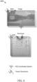
- Figure 6 illustrates an input 600 to the CDSM computer model 500.
- the input 600 includes an image 602, which is an example of the images 102, and a radar point cloud 604 as an example of the point cloud data.
- Figure 6 illustrates how, initially, the feature maps derived from the input 600 from intermediate layers of each network 100-2 and 502 are misaligned.
- CDSM can be used to align and fuse these sets of 3D features into a common BEV grid associated with the fusion predictions 516.
- the CDSM fusion block 514 can apply further CDSM techniques to aggregate and output the fusion predictions 516 derived from their combined sensor outputs.
- Figure 7 illustrates additional concepts related to CDSM fusion techniques described herein for low-level sensor fusion of sensor data from different domains.
- An example of the CDSM computer model 500 is provided by a neural network 700.
- the neural network 700 includes a CDSM layer and a radar network point cloud layer.
- the CDSM layer outputs feature maps of a 2D image, which are aligned to a BEV associated with a vehicle, and that is aligned to point cloud feature maps output from the radar layer.
- tensor dimensions are aligned in the neural network 700 to match their spatial orientation in a vehicle coordinate system (e.g., the BEV grid).
- a vehicle coordinate system e.g., the BEV grid
- Figure 8 illustrates a network 800 that implements the CDSM fusion block and fuses the aligned CDSM features from different sensors into a fused output.
- the CDSM fusion block can be divided into three stages: aggregation, BiFPN processing, and prediction head evaluation.
- the network 800 enables the low-level merging of information from both camera and radar views.
- camera feature maps from different scale levels are taken and aggregated onto a single BEV map. This is done to detect objects of various sizes in the camera plane. Due to perspective mapping, these feature maps correspond to specific regions in the BEV domain at a certain distance from the camera sensor. The distance ranges for features from each scale level are determined using the GradCAM visualization technique mentioned above. Additionally, during the aggregation of feature maps, consideration is given to the relation between the camera sensor's field of view and the output BEV grid. This ensures that the features are not placed in a 3D space that is not visible in the image.
- a features refinement step is performed. This step involves several 2D convolutional layers in the BEV domain. Similar to the concept of the backbone, the features are processed from detailed to more general, creating smaller grid representations of the same BEV area. This enables the extraction of relations between different feature maps throughout the training process in an end-to-end manner, instead of manually invoking them onto the model. It also generates higher-level features that capture larger areas in the BEV.
- the result of the refinement step is a set of three different BEV grid feature maps from the camera sensor in a 3D domain, which can be directly fused with point cloud feature maps.
- the fusion of camera and point cloud features becomes a relatively simple task now, as they have been converted into the same coordinate system.
- the aggregated and refined camera feature maps in BEV correspond spatially to those obtained during radar data processing.
- compatible grid sizes are ensured so that both grid tensors can be concatenated together, stacking camera and radar features for each grid cell along the channel dimension.
- Another BiFPN block is applied to the concatenated feature maps at different levels to further combine the information from both sensors into a single 3D internal representation. This representation is used in the prediction heads to generate the final 3D object predictions.
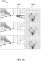
- Figures 9 and 10 illustrate example results of performing CDSM fusion in accordance with the described techniques.
- Results 900 are illustrated in Figure 9
- results 1000 are drawn in Figure 10 ; the results 900 and 1000 each depict, respectively from top to bottom, results of a camera-only test, a radar-only test, and a CDSM fusion test.
- a vehicle system or simulation executes three different computer models that are separately trained and evaluated for performance using the NuScenes dataset.
- Each shows, from top to bottom, a 2D image side by side with a corresponding 3D BEV that is populated with object predictions of one of three different models: a camera only model, a radar only model, and a CDSM fusion model like that described above (e.g., in Figures 5 , 6 , 7 , and 8 ).
- Each model was trained on the NuScenes dataset and then evaluated separately based on one or more KPIs available, including official rankings (e.g., NuScenes rankings), for comparison with other state of the art systems used in 3D object detection.
- the results 900 include an image 902 and a corresponding 3D BEV 904 representation generated by each separate model that is tested. LiDAR point cloud data is shown added to the 3D BEV 904 for further reference in the BEV view.
- Table III includes a comparison between camera only, radar only, and different fusion models, including the example CDSM fusion model, when processing the image 902 and/or 3D radar data to derive the 3D BEV 904. The two different modalities are labeled in the Table III as C for camera, R for radar, or C+R for camera and radar together.
- the results 1000 include an image 1002 and a corresponding 3D BEV 1004 representation generated by each separate model that is tested, for a different corner case than that tested in Figure 9 .
- LiDAR point cloud data is shown added to the 3D BEV 1004 for further reference in the BEV view.
- Table IV includes a comparison between lidar only, camera only, and various fusion models including the example CDSM fusion model, which process camera and radar in combination.
- CDSM fusion model which process camera and radar in combination.
- these three different modalities are labeled C for camera, R for radar, L for lidar, or C+R for camera and radar together.
- the different fusion models utilizes both sensors' data to improve upon each of them.
- the CDSM fusion model described herein achieve state of the art performance comparable to more complex systems that are too computing resource intensive for embedded (e.g., vehicle) applications.
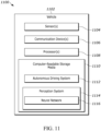
- FIG 11 illustrates an example configuration 1100 of a vehicle 1102 that may implement the techniques described herein to perform CDSM for monocular 3D object detection and/or low-level sensor fusion.
- the vehicle 1102 includes one or more sensors 1104, one or more communication devices 1106, one or more processors 1108, and computer-readable storage media (CRM) 1110.
- the vehicle 1102 is further equipped with an autonomous driving system 1112 that relies on object information from a perception system 1114.
- the perception system 1114 includes a neural network 1116 trained to perform the described techniques related to CDSM alignment and CDSM fusion.
- the neural network 1116 may be divided into several layers, where each upper layer uses information provided by lower layers. At least one of the layers of the neural network 1116 includes the computing system 100 and/or the architecture 200.
- the CRM 1110 stores instructions associated with the autonomous driving system 1112, the perception system 1114, and the neural network 1116.
- the sensors 1104 provide sensor data to the neural network 1116.
- the sensors 1104 may be mounted to, or integrated within, any portion of the vehicle 1102 to provide an instrumented field of view.
- the sensors 1104 produce raw information (e.g., low-level information as opposed to higher object-level information) about the vehicle 1102 and the physical surrounding environment.
- the sensors 1104 may include camera systems, radar systems, lidar systems, or ultrasonic systems to detect and track objects in the environment surrounding the vehicle 1102 and detect objects within a drivable area surrounding the vehicle 1102.
- Radar systems may provide information regarding the range, radial velocity, and azimuth angle of nearby objects.
- Lidar systems and ultrasonic systems may provide a map of reflecting objects and indicate range information associated with those objects.
- Camera systems may be used to provide range information or to determine object classes associated with nearby objects.
- the sensors 1104 may provide sensor data regarding objects, including 2D camera images, radar and/or lidar point cloud data, or other forms of low-level or raw perception sensor data.
- the sensor data can, for example, indicate a relative position (e.g., range and lateral positioning), heading, or speed relative to the vehicle 1102 for the objects, including stationary objects that make up a free space boundary.
- the sensors 1104 include combinations of different types of sensors, such as a radar system and a camera, which provide a larger instrument field-of-view or improved detection of objects over using just one type of sensor.
- the perception system 1114 may include a vehicle state estimator and an environment perception system.
- the vehicle state estimation layer utilizes raw data from the sensors 1104 to obtain accurate information about the vehicle 1102, including its position, speed, orientation (e.g., yaw), or yaw rate.
- the environment perception layer also uses data from sensors 1104 to provide information about the surrounding environment, both the dynamic world (e.g., moving cars and pedestrians) and the stationary world (e.g., guardrails).
- the topmost layers include the autonomous driving system 1112 that provide features and functions that support daily driving (e.g., lane keeping assistance) and the neural network 1116 that is responsible for processing the sensor data from the sensors 1104 to detect objects and output bounding boxes relative the 3D space (e.g., the GCCS) defined by the autonomous driving system 1112; a safe driving path from point A to point B can be inferred from the information output by the neural network 1116 to avoid colliding with any of the detected objects.
- the autonomous driving system 1112 that provide features and functions that support daily driving (e.g., lane keeping assistance)
- the neural network 1116 that is responsible for processing the sensor data from the sensors 1104 to detect objects and output bounding boxes relative the 3D space (e.g., the GCCS) defined by the autonomous driving system 1112; a safe driving path from point A to point B can be inferred from the information output by the neural network 1116 to avoid colliding with any of the detected objects.
- the communication devices 1106 include any radio or transceiver configured to send or receive signals for a vehicle.
- the communication devices 1106 may include telecommunication radios, satellite transceivers, and the like.
- the processors 1108 may be a microprocessor or a system-on-chip.
- the processors 1108 execute instructions stored in CRM 1110.
- the processors 1108 may process sensor data from the sensors 1104 by inputting an image from a 2D camera and transforming that input into a set of 3D features that are aggregated on a BEV grid. These 3D features can be combined using CDSM fusion to determine combined features identified by the sensors 1104, each relative a same frame of reference to the vehicle 1102 that is traveling in free space.
- the perception system 1114 or other part of the neural network 1116 may be operable to identify characteristics (e.g., relative positioning, range, and predicted tracks) and classifications of observable objects in the surrounding environment.
- the processor 1108 may then control the operation of the autonomous driving system 1112, the perception system 1114, and the neural network 1116 to cause the vehicle 1102 to navigate the environment and avoid potential collisions or unsafe driving.
- the processor 1108 may control, based on data from the sensors 1104, the perception system 1114 to request information about objects and their locations and sizes to determine a navigation path for the vehicle 1102 to avoid objects.
- Figure 12 illustrates an overview of techniques associated with performing CDSM for monocular 3D object detection and/or low-level CDSM sensor fusion.
- Figure 12 illustrates a process 1200 that is described in the context of being performed on the vehicle 1102 utilizing the computing system 100, the architecture 200, the CDSM computer model 500, the neural network 700, and the network 800.
- the processors 1108 may be configured to execute a CDSM 2D image feature extractor and aggregator that outputs 3D features for use in a BEV processing function (e.g., assisted driving).
- a BEV processing function e.g., assisted driving
- the process 1200 is shown optionally used as entry into a CDSM fusion algorithm.
- At step 1202 at least one input image is received from a camera of a vehicle including a 2D array of pixel information of the physical environment.
- the input image 102 is provided to the computing system 100 (e.g., from a camera of the sensors 1104).
- one or more objects associated with the potential targets are detected and/or classified. For example, another vehicle may be detected from the BEV grid 116.
- the vehicle is controlled to avoid collisions with the objects. For example, responsive to determining that the other vehicle is included in the at least one of the objects, and is near a travel path of the vehicle, the processors 1108 may control the vehicle 1102 to avoid a collision with that object.
- 3D point cloud data is received from a radar or lidar of the vehicle.
- the sensors 1104 include a radar configured to output radar data that is processed by the perception system 1114.
- Features are extracted from the 3D point cloud data for aggregation onto the BEV grid 116.
- the 3D image features are aggregated with the 3D point cloud features to generate a fused set of aggregated 3D features to the potential targets.
- the aggregated 3D features 114 are produced by aggregating the 3D image features 110 based on their extrapolated depth information to fit the BEV grid 116 in combination with the 3D feature maps 510 output from the CDSM computer model 500.
- the two sensor modalities can be used in combination for object classification and/or object detections that use the BEV grid 116.
- the steps 1210 and 1212 may be performed in response to the execution of the step 1216.
- another vehicle may be detected from the BEV grid 116 with greater accuracy from utilizing information derived from 3D features found in the input image 102 and the point cloud data.
- the vehicle 1102 is controlled to avoid collisions with the objects near a travel path.
- the techniques according to the present invention may be implemented in terms of a computer program which may be executed on any suitable data processing device comprising means (e.g., a memory and one or more processors operatively coupled to the memory) being configured accordingly.
- the computer program may be stored as computer-executable instructions on a non-transitory computer-readable medium.
- Embodiments of the present disclosure may be realized in any of various forms.
- the present invention may be realized as a computer-implemented method, a non-transitory computer-readable storage medium, or a computer system.
- a computing device may be configured to include a processor (or a set of processors) and a memory medium, where the memory medium stores program instructions, where the processor is configured to read and execute the program instructions from the memory medium, where the program instructions are executable to implement any of the various techniques described herein (or, any combination of the techniques described herein, or, any subset of any of the techniques described herein, or, any combination of such subsets).
- the device may be realized in any of various forms.
Landscapes
- Engineering & Computer Science (AREA)
- Theoretical Computer Science (AREA)
- Physics & Mathematics (AREA)
- General Physics & Mathematics (AREA)
- Multimedia (AREA)
- Computer Vision & Pattern Recognition (AREA)
- Evolutionary Computation (AREA)
- Artificial Intelligence (AREA)
- Health & Medical Sciences (AREA)
- General Health & Medical Sciences (AREA)
- Computing Systems (AREA)
- Software Systems (AREA)
- Medical Informatics (AREA)
- Databases & Information Systems (AREA)
- Life Sciences & Earth Sciences (AREA)
- Biomedical Technology (AREA)
- Molecular Biology (AREA)
- Computational Linguistics (AREA)
- General Engineering & Computer Science (AREA)
- Mathematical Physics (AREA)
- Data Mining & Analysis (AREA)
- Biophysics (AREA)
- Remote Sensing (AREA)
- Radar, Positioning & Navigation (AREA)
- Electromagnetism (AREA)
- Computer Networks & Wireless Communication (AREA)
- Biodiversity & Conservation Biology (AREA)
- Image Analysis (AREA)
Applications Claiming Priority (2)
| Application Number | Priority Date | Filing Date | Title |
|---|---|---|---|
| US202363512045P | 2023-07-05 | 2023-07-05 | |
| US18/756,419 US20250014354A1 (en) | 2023-07-05 | 2024-06-27 | Cross-Domain Spatial Matching For Monocular 3D Object Detection And/Or Low-Level Sensor Fusion |
Publications (1)
| Publication Number | Publication Date |
|---|---|
| EP4530982A1 true EP4530982A1 (de) | 2025-04-02 |
Family
ID=91782370
Family Applications (1)
| Application Number | Title | Priority Date | Filing Date |
|---|---|---|---|
| EP24186060.0A Pending EP4530982A1 (de) | 2023-07-05 | 2024-07-02 | Domänenübergreifende räumliche anpassung für monokulare 3d-objekterkennung und/oder low-level-sensorfusion |
Country Status (3)
| Country | Link |
|---|---|
| US (1) | US20250014354A1 (de) |
| EP (1) | EP4530982A1 (de) |
| CN (1) | CN119273945A (de) |
Families Citing this family (4)
| Publication number | Priority date | Publication date | Assignee | Title |
|---|---|---|---|---|
| US12464247B2 (en) * | 2023-09-15 | 2025-11-04 | Robert Bosch Gmbh | Device and method for surround view camera system |
| US20250157204A1 (en) * | 2023-11-14 | 2025-05-15 | Qualcomm Incorporated | Asynchronous multimodal feature fusion |
| US12614395B2 (en) * | 2023-11-16 | 2026-04-28 | Qualcomm Incorporated | Three-dimensional (3D) object detection based on multiple two-dimensional (2D) views |
| CN121686246B (zh) * | 2026-02-09 | 2026-04-21 | 贵州省测绘产品质量监督检验站(贵州省测绘仪器计量检定站贵州省测绘行业特有工种职业技能鉴定站) | 基于地理实体导向的实景三维模型分类方法和系统 |
-
2024
- 2024-06-27 US US18/756,419 patent/US20250014354A1/en active Pending
- 2024-07-02 EP EP24186060.0A patent/EP4530982A1/de active Pending
- 2024-07-05 CN CN202410899425.4A patent/CN119273945A/zh active Pending
Non-Patent Citations (5)
| Title |
|---|
| DANIEL DWORAK ET AL: "Cross-Domain Spatial Matching for Camera and Radar Sensor Data Fusion in Autonomous Vehicle Perception System", ARXIV.ORG, CORNELL UNIVERSITY LIBRARY, 201 OLIN LIBRARY CORNELL UNIVERSITY ITHACA, NY 14853, 25 April 2024 (2024-04-25), XP091737997 * |
| DWORAK DANIEL ET AL: "Cross-Domain Spatial Matching for Monocular 3D Object Detection", IECON 2023- 49TH ANNUAL CONFERENCE OF THE IEEE INDUSTRIAL ELECTRONICS SOCIETY, IEEE, 16 October 2023 (2023-10-16), pages 1 - 6, XP034470346, DOI: 10.1109/IECON51785.2023.10311851 * |
| LEI YANG ET AL: "Lite-FPN for Keypoint-based Monocular 3D Object Detection", ARXIV.ORG, CORNELL UNIVERSITY LIBRARY, 201 OLIN LIBRARY CORNELL UNIVERSITY ITHACA, NY 14853, 12 June 2021 (2021-06-12), XP081981025 * |
| LIU ZECHEN ET AL: "SMOKE: Single-Stage Monocular 3D Object Detection via Keypoint Estimation", 2020 IEEE/CVF CONFERENCE ON COMPUTER VISION AND PATTERN RECOGNITION WORKSHOPS (CVPRW), IEEE, 14 June 2020 (2020-06-14), pages 4289 - 4298, XP033798991, DOI: 10.1109/CVPRW50498.2020.00506 * |
| ZHAO YANGYU ZHAOYANGYU@STU SCU EDU CN ET AL: "3D Object Detection Based on Feature Pyramid Network", 19TH BRAZILIAN SYMPOSIUM ON SOFTWARE QUALITY, ACMPUB27, NEW YORK, NY, USA, 13 November 2020 (2020-11-13), pages 1 - 7, XP058585999, ISBN: 978-1-4503-8976-1, DOI: 10.1145/3441250.3441257 * |
Also Published As
| Publication number | Publication date |
|---|---|
| CN119273945A (zh) | 2025-01-07 |
| US20250014354A1 (en) | 2025-01-09 |
Similar Documents
| Publication | Publication Date | Title |
|---|---|---|
| EP4530982A1 (de) | Domänenübergreifende räumliche anpassung für monokulare 3d-objekterkennung und/oder low-level-sensorfusion | |
| US20230054914A1 (en) | Vehicle localization | |
| CN112292711B (zh) | 关联lidar数据和图像数据 | |
| US11670038B2 (en) | Processing point clouds using dynamic voxelization | |
| US20230072637A1 (en) | Vehicle Drivable Area Detection Method, System, and Autonomous Vehicle Using the System | |
| US11530924B2 (en) | Apparatus and method for updating high definition map for autonomous driving | |
| US10867189B2 (en) | Systems and methods for lane-marker detection | |
| CA2950791C (en) | Binocular visual navigation system and method based on power robot | |
| Fleck et al. | Towards large scale urban traffic reference data: Smart infrastructure in the test area autonomous driving baden-württemberg | |
| US20240077617A1 (en) | Perception for point clouds | |
| US11961304B2 (en) | Systems and methods for deriving an agent trajectory based on multiple image sources | |
| US11961241B2 (en) | Systems and methods for deriving an agent trajectory based on tracking points within images | |
| WO2020215254A1 (zh) | 车道线地图的维护方法、电子设备与存储介质 | |
| US20240302517A1 (en) | Radar perception | |
| CN110263713A (zh) | 车道线检测方法、装置、电子设备及存储介质 | |
| US20240265707A1 (en) | Systems and methods for deriving an agent trajectory based on multiple image sources | |
| CN109117690A (zh) | 可行驶区域检测方法、装置、设备及存储介质 | |
| US12260573B2 (en) | Adversarial approach to usage of lidar supervision to image depth estimation | |
| US20260087827A1 (en) | Method for automatically annotating an obstacle, electronic device and storage medium | |
| CN115965961B (zh) | 局部到全局的多模态融合方法、系统、设备及存储介质 | |
| Manivannan et al. | Vision based intelligent vehicle steering control using single camera for automated highway system | |
| Kim et al. | Data association leveraging extrinsic parameter consistency for multi-object detection in maritime environment | |
| JP2023011912A (ja) | 走行環境における交通オブジェクトの融合及び関連付け方法、装置並びにエッジコンピューティングデバイス | |
| KR20210051513A (ko) | 지도 생성 방법 및 장치 | |
| Ye et al. | Deep Learning and Geo-Fencing Based Free Parking Spot Detection Using a Camera Mounted on a Truck |
Legal Events
| Date | Code | Title | Description |
|---|---|---|---|
| PUAI | Public reference made under article 153(3) epc to a published international application that has entered the european phase |
Free format text: ORIGINAL CODE: 0009012 |
|
| STAA | Information on the status of an ep patent application or granted ep patent |
Free format text: STATUS: THE APPLICATION HAS BEEN PUBLISHED |
|
| AK | Designated contracting states |
Kind code of ref document: A1 Designated state(s): AL AT BE BG CH CY CZ DE DK EE ES FI FR GB GR HR HU IE IS IT LI LT LU LV MC ME MK MT NL NO PL PT RO RS SE SI SK SM TR |
|
| STAA | Information on the status of an ep patent application or granted ep patent |
Free format text: STATUS: REQUEST FOR EXAMINATION WAS MADE |
|
| 17P | Request for examination filed |
Effective date: 20250911 |