EP4530885A1 - Vorrichtung und verfahren zur verbesserung der zero-shot-klassifizierung - Google Patents
Vorrichtung und verfahren zur verbesserung der zero-shot-klassifizierung Download PDFInfo
- Publication number
- EP4530885A1 EP4530885A1 EP23199960.8A EP23199960A EP4530885A1 EP 4530885 A1 EP4530885 A1 EP 4530885A1 EP 23199960 A EP23199960 A EP 23199960A EP 4530885 A1 EP4530885 A1 EP 4530885A1
- Authority
- EP
- European Patent Office
- Prior art keywords
- class
- sub
- text
- sensor signal
- encoder
- Prior art date
- Legal status (The legal status is an assumption and is not a legal conclusion. Google has not performed a legal analysis and makes no representation as to the accuracy of the status listed.)
- Pending
Links
Images



Classifications
-
- G—PHYSICS
- G06—COMPUTING OR CALCULATING; COUNTING
- G06F—ELECTRIC DIGITAL DATA PROCESSING
- G06F16/00—Information retrieval; Database structures therefor; File system structures therefor
- G06F16/50—Information retrieval; Database structures therefor; File system structures therefor of still image data
- G06F16/55—Clustering; Classification
-
- G—PHYSICS
- G06—COMPUTING OR CALCULATING; COUNTING
- G06V—IMAGE OR VIDEO RECOGNITION OR UNDERSTANDING
- G06V10/00—Arrangements for image or video recognition or understanding
- G06V10/70—Arrangements for image or video recognition or understanding using pattern recognition or machine learning
- G06V10/82—Arrangements for image or video recognition or understanding using pattern recognition or machine learning using neural networks
-
- G—PHYSICS
- G06—COMPUTING OR CALCULATING; COUNTING
- G06F—ELECTRIC DIGITAL DATA PROCESSING
- G06F16/00—Information retrieval; Database structures therefor; File system structures therefor
- G06F16/70—Information retrieval; Database structures therefor; File system structures therefor of video data
- G06F16/75—Clustering; Classification
-
- G—PHYSICS
- G06—COMPUTING OR CALCULATING; COUNTING
- G06N—COMPUTING ARRANGEMENTS BASED ON SPECIFIC COMPUTATIONAL MODELS
- G06N3/00—Computing arrangements based on biological models
- G06N3/02—Neural networks
- G06N3/04—Architecture, e.g. interconnection topology
- G06N3/045—Combinations of networks
-
- G—PHYSICS
- G06—COMPUTING OR CALCULATING; COUNTING
- G06N—COMPUTING ARRANGEMENTS BASED ON SPECIFIC COMPUTATIONAL MODELS
- G06N3/00—Computing arrangements based on biological models
- G06N3/02—Neural networks
- G06N3/08—Learning methods
-
- G—PHYSICS
- G06—COMPUTING OR CALCULATING; COUNTING
- G06V—IMAGE OR VIDEO RECOGNITION OR UNDERSTANDING
- G06V10/00—Arrangements for image or video recognition or understanding
- G06V10/70—Arrangements for image or video recognition or understanding using pattern recognition or machine learning
- G06V10/74—Image or video pattern matching; Proximity measures in feature spaces
- G06V10/761—Proximity, similarity or dissimilarity measures
-
- G—PHYSICS
- G06—COMPUTING OR CALCULATING; COUNTING
- G06V—IMAGE OR VIDEO RECOGNITION OR UNDERSTANDING
- G06V10/00—Arrangements for image or video recognition or understanding
- G06V10/70—Arrangements for image or video recognition or understanding using pattern recognition or machine learning
- G06V10/77—Processing image or video features in feature spaces; using data integration or data reduction, e.g. principal component analysis [PCA] or independent component analysis [ICA] or self-organising maps [SOM]; Blind source separation
- G06V10/778—Active pattern-learning, e.g. online learning of image or video features
-
- G—PHYSICS
- G06—COMPUTING OR CALCULATING; COUNTING
- G06F—ELECTRIC DIGITAL DATA PROCESSING
- G06F16/00—Information retrieval; Database structures therefor; File system structures therefor
- G06F16/30—Information retrieval; Database structures therefor; File system structures therefor of unstructured textual data
- G06F16/35—Clustering; Classification
Definitions
- the invention concerns a method for improving zero-shot classification by a combination of image and text encoders, wherein weightings of prompts for the text encoder are optimized, and a method for operating an actuator, a computer program and a machine-readable storage medium, and a system.
- Zero-shot classifiers built upon models like CLIP https://arxiv.org/abs/2103.00020
- CoCa https://arxiv.org/abs/2205.01917
- These prompt templates can be hand-designed (https://arxiv.org/abs/2103.00020), generated by a large language model (https://arxiv.org/abs/2210.07183) or randomly generated (https://arxiv.org/abs/2306.07282).
- a set of text queries per class is obtained. These are encoded by the CLIP text encoder and the resulting encoded queries (per class) are simply averaged.
- this datum is first encoded by the encoder of the respective modality (e.g. image encoder) and then the cosine similarity of the encoded datum with every (averaged) class query is computed. The datum is then assigned to the class with the maximum similarity.
- the improvement over the prior art is given by at least that the inventors propose not to simply average the encoded text prompts (per class), but take a weighted average, where weights are automatically determined for every datum separately. Weights are determined such that prompt templates whose embeddings (across classes) are closer to the embedding of the respective datum get a higher weight than those being less similar. This can intuitively be motivated by closer text encodings corresponding to text prompts that describe the datum better than ones with lower similarity.
- the invention improves performance of zero-shot classifiers on many types of data with very little inference time overhead, and still being fully zero-shot because it works without requiring any labels or other datapoints from the target domain. It makes no assumptions on the underlying multi-model model and can thus be broadly applied.
- the encoders are configured to encode their inputs to a latent representation.
- a latent representation can be understood as a point in a latent space.
- a latent space also known as a latent feature space or embedding space, is an embedding within a manifold in which items resembling each other are positioned closer to one another in the latent space. Both sensor signal encoder and text encoder can share the same latent space.
- the method of classifying starts with generating a plurality of text prompts, wherein for each class several text prompts characterizing the corresponding class are instantiated. This step can be carried out by manually writing the prompts and/or by automatically generating them, e.g. as described above in the prior art section.
- a text prompt can be a text for processing by a foundation model.
- the first latent representation ( e ( x ) ) and second latent representations ( e ij t ) are normalized.
- the instantiation of the prompts is generated by inserting class names into predefined templates of text prompts.
- class properties can be inserted into the templates. It is noted that other known methods for filling out text prompt templates from the literature can be utilized.
- the sensor signals can be images.
- image basically includes any distribution of information arranged in a two- or multi-dimensional grid.
- This information can be, for example, intensity values of image pixels captured with any imaging modality, such as an optical camera, thermal imaging camera or ultrasound.
- any other data such as audio data, radar data or LIDAR data, can also be translated into images and then classified in the same way or can be provided as an additional input for the encoders.
- the classification can be carried out based on low-level features (e.g. edges or pixel attributes for images), in particular the determination of the latent representations.
- low-level features e.g. edges or pixel attributes for images
- the encoders are foundation models, in particular the encoders of CLIP or CoCa.
- the assigned class aka the classification, can then be used for providing an actuator control signal for controlling an actuator.
- a control system/method for operating the actuator is proposed. Said control system/method being configured to operate said actuator in accordance with the actuator control signal.
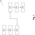
- Figure 1 shows in a first embodiment a known method 20 for zero-shot classification.
- This modification of the known zero-shot classifier can be referred to as "auto-tuned" because its weights w are automatically adapted for every input.
- a heuristic for choosing the learning rate automatically can be used. It is noted that in a zero-shot setting, there is by definition no labeled data on which free parameters like the learning rate can be tuned. Because of this, free parameters is perferably selected globally in a dataset-independent manner. However, a global choice for the learning rate ⁇ can be problematic since the scale of the gradient ⁇ ⁇ logsumexp(s) depends on the dataset and the learning rate would have to be adapted accordingly. Because of this, it is proposed to use a different parameterization in which the free parameter is easier interpreted and ⁇ is a derived quantity.
- the standard, untuned uniform weights have maximum entropy log 2 K and one can set the target entropy to ⁇ * log 2 K , where the entropy reduction factor ⁇ is the new free parameter.
- a preferred root finding method is the bisection method ( https://en.wikipedia.org/wiki/Bisection method ).
- the root ⁇ is the determined learning rate.
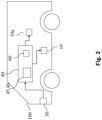
- a sensor 30 senses a condition of the actuator system.
- the sensor 30 may comprise several sensors.
- sensor 30 is an optical sensor that takes images of the environment.
- An output signal S of sensor 30 (or, in case the sensor 30 comprises a plurality of sensors, an output signal S for each of the sensors) which encodes the sensed condition is transmitted to the control system 40.
- control system 40 receives a stream of sensor signals S. It then computes a series of actuator control commands A depending on the stream of sensor signals S, which are then transmitted to actuator unit 10 that converts the control commands A into mechanical movements or changes in physical quantities.
- the actuator unit 10 may convert the control command A into an electric, hydraulic, pneumatic, thermal, magnetic and/or mechanical movement or change.
- Specific yet non-limiting examples include electrical motors, electroactive polymers, hydraulic cylinders, piezoelectric actuators, pneumatic actuators, servomechanisms, solenoids, stepper motors, etc.
- Control system 40 receives the stream of sensor signals S of sensor 30 in an optional receiving unit 50.
- Receiving unit 50 transforms the sensor signals S into input signals x.
- each sensor signal S may directly be taken as an input signal x.
- Input signal x may, for example, be given as an excerpt from sensor signal S.
- sensor signal S may be processed to yield input signal x.
- Input signal x comprises image data corresponding to an image recorded by sensor 30. In other words, input signal x is provided in accordance with sensor signal S.
- Input signal x is then passed on to the zero-shot classification method e.g. according to the second embodiment of Fig. 1 , that is referred to as classifier 60 in the following, which may, for example, be given by an artificial neural network.
- Classifier 60 is parametrized by parameters ⁇ , which are stored in and provided by parameter storage St 1 .
- Classifier 60 determines output signals y from input signals x.
- the output signal y comprises information that assigns one or more labels to the input signal x.
- Output signals y are transmitted to an optional conversion unit 80, which converts the output signals y into the control commands A.
- Actuator control commands A are then transmitted to actuator unit 10 for controlling actuator unit 10 accordingly.
- output signals y may directly be taken as control commands A.
- Actuator unit 10 receives actuator control commands A, is controlled accordingly and carries out an action corresponding to actuator control commands A.
- Actuator unit 10 may comprise a control logic which transforms actuator control command A into a further control command, which is then used to control actuator 10.
- control system 40 may comprise sensor 30. In even further embodiments, control system 40 alternatively or additionally may comprise actuator 10.
- classifier 60 may be designed to identify lanes on a road ahead, e.g. by classifying a road surface and markings on said road and identifying lanes as patches of road surface between said markings. Based on an output of a navigation system, a suitable lane for pursuing a chosen path can then be selected and depending on a present lane and said target lane, it may then be decided whether vehicle 60 is to switch lanes or stay in said present lane. Control command A may then be computed by e.g. retrieving a predefined motion pattern from a database corresponding to said identified action.
- corresponding constraints on possible motion patterns of vehicle 60 may then be retrieved from e.g. a database, a future path of vehicle 60 commensurate with said constraints may be computed, and said actuator control command A may be computed to steer the vehicle such as to execute said trajectory.
- a projected future behavior of said pedestrians and/or vehicles may be estimated, and based on said estimated future behavior, a trajectory may then be selected such as to avoid collision with said pedestrian and/or said vehicle, and said actuator control command A may be computed to steer the vehicle such as to execute said trajectory.
- control system 40 may comprise a processor 45 (or a plurality of processors) and at least one machine-readable storage medium 46 on which instructions are stored which, if carried out, cause control system 40 to carry out a method according to one aspect of the invention.
- control system 40 is used to control the actuator, which is an at least partially autonomous robot, e.g. an at least partially autonomous vehicle 100.
- Sensor 30 may comprise one or more video sensors and/or one or more radar sensors and/or one or more ultrasonic sensors and/or one or more LiDAR sensors and or one or more position sensors (like e.g. GPS). Some or all of these sensors are preferably but not necessarily integrated in vehicle 100.
- sensor 30 may comprise an information system for determining a state of the actuator system.
- One example for such an information system is a weather information system which determines a present or future state of the weather in environment 20.
- the classifier 60 may for example detect objects in the vicinity of the at least partially autonomous robot.
- Output signal y may comprise an information which characterizes where objects are located in the vicinity of the at least partially autonomous robot.
- Control command A may then be determined in accordance with this information, for example to avoid collisions with said detected objects.
- Actuator unit 10 which is preferably integrated in vehicle 100, may be given by a brake, a propulsion system, an engine, a drivetrain, or a steering of vehicle 100.
- Actuator control commands A may be determined such that actuator (or actuators) unit 10 is/are controlled such that vehicle 100 avoids collisions with said detected objects.
- Detected objects may also be classified according to what the classifier 60 deems them most likely to be, e.g. pedestrians or trees, and actuator control commands A may be determined depending on the classification.
- the at least partially autonomous robot may be given by another mobile robot (not shown), which may, for example, move by flying, swimming, diving or stepping.
- the mobile robot may, inter alia, be an at least partially autonomous lawn mower, or an at least partially autonomous cleaning robot.
- actuator command control A may be determined such that propulsion unit and/or steering and/or brake of the mobile robot are controlled such that the mobile robot may avoid collisions with said identified objects.
- the at least partially autonomous robot may be given by a gardening robot (not shown), which uses sensor 30, preferably an optical sensor, to determine a state of plants in the environment 20.
- Actuator unit 10 may be a nozzle for spraying chemicals.
- an actuator control command A may be determined to cause actuator unit 10 to spray the plants with a suitable quantity of suitable chemicals.
- the at least partially autonomous robot may be given by a domestic appliance (not shown), like e.g. a washing machine, a stove, an oven, a microwave, or a dishwasher.
- Sensor 30, e.g. an optical sensor may detect a state of an object which is to undergo processing by the household appliance.
- Sensor 30 may detect a state of the laundry inside the washing machine.
- Actuator control signal A may then be determined depending on a detected material of the laundry.
- control system 40 is used to control a manufacturing machine 11, e.g. a solder mounter, punch cutter, a cutter or a gun drill) of a manufacturing system 200, e.g. as part of a production line.
- a manufacturing machine e.g. a solder mounter, punch cutter, a cutter or a gun drill
- Sensor 30 may be given by an optical sensor which captures properties of e.g. a manufactured product 12.
- Classifier 60 may determine a state of the manufactured product 12 from these captured properties.
- Actuator unit 10 which controls manufacturing machine 11 may then be controlled depending on the determined state of the manufactured product 12 for a subsequent manufacturing step of manufactured product 12. Or it may be envisioned that actuator unit 10 is controlled during manufacturing of a subsequent manufactured product 12 depending on the determined state of the manufactured product 12.
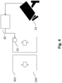
- Access control system may be designed to physically control access. It may, for example, comprise a door 401.
- Sensor 30 is configured to detect a scene that is relevant for deciding whether access is to be granted or not. It may for example be an optical sensor for providing image or video data, for detecting a person's face.
- Classifier 60 may be configured to interpret this image or video data e.g. by matching identities with known people stored in a database, thereby determining an identity of the person.
- Actuator control signal A may then be determined depending on the interpretation of classifier 60, e.g. in accordance with the determined identity.
- Actuator unit 10 may be a lock which grants access or not depending on actuator control signal A.
- a non-physical, logical access control is also possible.
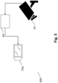
- control system 40 controls a surveillance system 400.
- Sensor 30 is configured to detect a scene that is under surveillance.
- Control system does not necessarily control an actuator 10, but a display 10a.
- the machine learning system 60 may determine a classification of a scene, e.g. whether the scene detected by optical sensor 30 is suspicious.
- Actuator control signal A which is transmitted to display 10a may then e.g. be configured to cause display 10a to adjust the displayed content dependent on the determined classification, e.g. to highlight an object that is deemed suspicious by machine learning system 60.
- control system 40 is used for controlling an automated personal assistant 250.
- Sensor 30 may be an optic sensor, e.g. for receiving video images of a gestures of user 249.
- sensor 30 may also be an audio sensor e.g. for receiving a voice command of user 249.
- Control system 40 determines actuator control commands A for controlling the automated personal assistant 250.
- the actuator control commands A are determined in accordance with sensor signal S of sensor 30. Sensor signal S is transmitted to the control system 40.
- classifier 60 may be configured to e.g. carry out a gesture recognition algorithm to identify a gesture made by user 249.
- Control system 40 may then determine an actuator control command A for transmission to the automated personal assistant 250. It then transmits said actuator control command A to the automated personal assistant 250.
- actuator control command A may be determined in accordance with the identified user gesture recognized by classifier 60. It may then comprise information that causes the automated personal assistant 250 to retrieve information from a database and output this retrieved information in a form suitable for reception by user 249.
- control system 40 controls a domestic appliance (not shown) controlled in accordance with the identified user gesture.
- the domestic appliance may be a washing machine, a stove, an oven, a microwave or a dishwasher.
- Shown in figure 7 is an embodiment of a control system 40 for controlling an imaging system 500, for example an MRI apparatus, x-ray imaging apparatus or ultrasonic imaging apparatus.
- Sensor 30 may, for example, be an imaging sensor.
- Machine learning system 60 may then determine a classification of all or part of the sensed image. Actuator control signal A may then be chosen in accordance with this classification, thereby controlling display 10a. For example, machine learning system 60 may interpret a region of the sensed image to be potentially anomalous. In this case, actuator control signal A may be determined to cause display 10a to display the imaging and highlighting the potentially anomalous region.
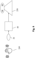
- Shown in figure 8 is an embodiment of a system 500.
- the system 500 comprises a provider system 51, which provides input images. Input images are fed to the encoders 52, which determines latent representations from them. Said latent representations are supplied to an assessor 53, which determines the classification as discussed above in S26.
- the procedures executed by the training device 500 may be implemented as a computer program stored on a machine-readable storage medium 54 and executed by a processor 55.
- the term "computer” covers any device for the processing of pre-defined calculation instructions. These calculation instructions can be in the form of software, or in the form of hardware, or also in a mixed form of software and hardware.
Landscapes
- Engineering & Computer Science (AREA)
- Theoretical Computer Science (AREA)
- Physics & Mathematics (AREA)
- General Physics & Mathematics (AREA)
- Evolutionary Computation (AREA)
- Databases & Information Systems (AREA)
- Computing Systems (AREA)
- General Health & Medical Sciences (AREA)
- Software Systems (AREA)
- Artificial Intelligence (AREA)
- Health & Medical Sciences (AREA)
- Computer Vision & Pattern Recognition (AREA)
- Multimedia (AREA)
- Medical Informatics (AREA)
- Data Mining & Analysis (AREA)
- General Engineering & Computer Science (AREA)
- Life Sciences & Earth Sciences (AREA)
- Biomedical Technology (AREA)
- Biophysics (AREA)
- Computational Linguistics (AREA)
- Molecular Biology (AREA)
- Mathematical Physics (AREA)
- Image Analysis (AREA)
- Information Retrieval, Db Structures And Fs Structures Therefor (AREA)
Priority Applications (3)
| Application Number | Priority Date | Filing Date | Title |
|---|---|---|---|
| EP23199960.8A EP4530885A1 (de) | 2023-09-27 | 2023-09-27 | Vorrichtung und verfahren zur verbesserung der zero-shot-klassifizierung |
| US18/883,333 US20250104411A1 (en) | 2023-09-27 | 2024-09-12 | Device and method to improve zero-shot classification |
| CN202411350017.XA CN119740085A (zh) | 2023-09-27 | 2024-09-26 | 用以改进零样本分类的设备和方法 |
Applications Claiming Priority (1)
| Application Number | Priority Date | Filing Date | Title |
|---|---|---|---|
| EP23199960.8A EP4530885A1 (de) | 2023-09-27 | 2023-09-27 | Vorrichtung und verfahren zur verbesserung der zero-shot-klassifizierung |
Publications (1)
| Publication Number | Publication Date |
|---|---|
| EP4530885A1 true EP4530885A1 (de) | 2025-04-02 |
Family
ID=88207572
Family Applications (1)
| Application Number | Title | Priority Date | Filing Date |
|---|---|---|---|
| EP23199960.8A Pending EP4530885A1 (de) | 2023-09-27 | 2023-09-27 | Vorrichtung und verfahren zur verbesserung der zero-shot-klassifizierung |
Country Status (3)
| Country | Link |
|---|---|
| US (1) | US20250104411A1 (de) |
| EP (1) | EP4530885A1 (de) |
| CN (1) | CN119740085A (de) |
Citations (1)
| Publication number | Priority date | Publication date | Assignee | Title |
|---|---|---|---|---|
| CN115658954A (zh) * | 2022-10-28 | 2023-01-31 | 华东师范大学 | 一种基于提示学习的跨模态检索对抗防御方法 |
-
2023
- 2023-09-27 EP EP23199960.8A patent/EP4530885A1/de active Pending
-
2024
- 2024-09-12 US US18/883,333 patent/US20250104411A1/en active Pending
- 2024-09-26 CN CN202411350017.XA patent/CN119740085A/zh active Pending
Patent Citations (1)
| Publication number | Priority date | Publication date | Assignee | Title |
|---|---|---|---|---|
| CN115658954A (zh) * | 2022-10-28 | 2023-01-31 | 华东师范大学 | 一种基于提示学习的跨模态检索对抗防御方法 |
Non-Patent Citations (1)
| Title |
|---|
| OR PATASHNIK ET AL: "StyleCLIP: Text-Driven Manipulation of StyleGAN Imagery", ARXIV.ORG, CORNELL UNIVERSITY LIBRARY, 201 OLIN LIBRARY CORNELL UNIVERSITY ITHACA, NY 14853, 31 March 2021 (2021-03-31), XP081920254 * |
Also Published As
| Publication number | Publication date |
|---|---|
| CN119740085A (zh) | 2025-04-01 |
| US20250104411A1 (en) | 2025-03-27 |
Similar Documents
| Publication | Publication Date | Title |
|---|---|---|
| Handmann et al. | An image processing system for driver assistance | |
| EP3896613B1 (de) | Vorrichtung und verfahren zum trainieren eines klassifikators und beurteilen der robustheit eines klassifikators | |
| EP3629237B1 (de) | Vorrichtung und verfahren zur verbesserung der robustheit gegenüber »kontradiktorischen beispielen | |
| US12384411B2 (en) | Systems and methods for distribution-aware goal prediction for modular autonomous vehicle control | |
| EP4156076B1 (de) | Vorrichtung und verfahren zur verbesserung der erzeugung synthetischer bilder der bild-zu-bild-übersetzung von industriellen bildern | |
| US12277696B2 (en) | Data augmentation for domain generalization | |
| US20250104394A1 (en) | Scalable prompt learning for large vision-language models | |
| EP4592904A1 (de) | Training eines kodierers zur objekterkennung unter verwendung von fundamentmodellen | |
| Zhang et al. | Vehicle detection method for intelligent vehicle at night time based on video and laser information | |
| US12354331B2 (en) | Computer-implemented method for analyzing relevance of visual parameters for training a computer vision model | |
| US12248878B2 (en) | Device and method for training a neuronal network | |
| US20210319267A1 (en) | Device and method for training a classifier | |
| EP3923192A1 (de) | Vorrichtung und verfahren zum trainieren und testen eines klassifikators | |
| Sharma et al. | BEVSeg2TP: Surround view camera bird's-eye-view based joint vehicle segmentation and ego vehicle trajectory prediction | |
| EP3798913A1 (de) | Vorrichtung und verfahren zur verbesserung der robustheit gegenüber kontradiktorischen beispielen | |
| EP4530885A1 (de) | Vorrichtung und verfahren zur verbesserung der zero-shot-klassifizierung | |
| EP3866071B1 (de) | Vorrichtung und verfahren zur klassifizierung von bildern unter verwendung einer aufmerksamkeitsschicht | |
| Du et al. | FP-MOS: Frame-to-frame prediction for dynamic object segmentation with LiDAR data | |
| Cao et al. | Design and Implementation of a Vision-Based Vehicle Control System for Operational Commands via Human Keypoints Recognition | |
| US20260024224A1 (en) | Unified model for 3d object detection and object-centric neural reconstruction | |
| US20250363348A1 (en) | Device and method of reparametrizating a residual network for computational efficiency | |
| US20250104405A1 (en) | Attributing predictive uncertainties in real-world classification with adversarial gradient aggregation | |
| US20260044737A1 (en) | Device and method for one-shot neural architecture search with unlabeled data | |
| von Seelen et al. | Image processing of dynamic scenes | |
| Paletta et al. | Selective visual attention in object detection processes |
Legal Events
| Date | Code | Title | Description |
|---|---|---|---|
| PUAI | Public reference made under article 153(3) epc to a published international application that has entered the european phase |
Free format text: ORIGINAL CODE: 0009012 |
|
| STAA | Information on the status of an ep patent application or granted ep patent |
Free format text: STATUS: THE APPLICATION HAS BEEN PUBLISHED |
|
| AK | Designated contracting states |
Kind code of ref document: A1 Designated state(s): AL AT BE BG CH CY CZ DE DK EE ES FI FR GB GR HR HU IE IS IT LI LT LU LV MC ME MK MT NL NO PL PT RO RS SE SI SK SM TR |
|
| STAA | Information on the status of an ep patent application or granted ep patent |
Free format text: STATUS: REQUEST FOR EXAMINATION WAS MADE |
|
| 17P | Request for examination filed |
Effective date: 20251002 |