EP4530705A1 - Kontaktlinse - Google Patents
Kontaktlinse Download PDFInfo
- Publication number
- EP4530705A1 EP4530705A1 EP24168920.7A EP24168920A EP4530705A1 EP 4530705 A1 EP4530705 A1 EP 4530705A1 EP 24168920 A EP24168920 A EP 24168920A EP 4530705 A1 EP4530705 A1 EP 4530705A1
- Authority
- EP
- European Patent Office
- Prior art keywords
- section
- lens body
- azimuth angle
- toric lens
- contact lens
- Prior art date
- Legal status (The legal status is an assumption and is not a legal conclusion. Google has not performed a legal analysis and makes no representation as to the accuracy of the status listed.)
- Pending
Links
Images


Classifications
-
- G—PHYSICS
- G02—OPTICS
- G02C—SPECTACLES; SUNGLASSES OR GOGGLES INSOFAR AS THEY HAVE THE SAME FEATURES AS SPECTACLES; CONTACT LENSES
- G02C7/00—Optical parts
- G02C7/02—Lenses; Lens systems ; Methods of designing lenses
- G02C7/04—Contact lenses for the eyes
- G02C7/048—Means for stabilising the orientation of lenses in the eye
-
- G—PHYSICS
- G02—OPTICS
- G02C—SPECTACLES; SUNGLASSES OR GOGGLES INSOFAR AS THEY HAVE THE SAME FEATURES AS SPECTACLES; CONTACT LENSES
- G02C7/00—Optical parts
- G02C7/02—Lenses; Lens systems ; Methods of designing lenses
- G02C7/04—Contact lenses for the eyes
- G02C7/049—Contact lenses having special fitting or structural features achieved by special materials or material structures
-
- G—PHYSICS
- G02—OPTICS
- G02C—SPECTACLES; SUNGLASSES OR GOGGLES INSOFAR AS THEY HAVE THE SAME FEATURES AS SPECTACLES; CONTACT LENSES
- G02C7/00—Optical parts
- G02C7/02—Lenses; Lens systems ; Methods of designing lenses
- G02C7/024—Methods of designing ophthalmic lenses
Definitions
- the present invention relates to a contact lens, and more particularly to a contact lens for astigmatism.
- Positioning of contact lenses is extremely important to a contact lens for astigmatism. If a positioning effect of the contact lens is not good, the contact lens can easily rotate while being worn, such that the ideal vision correction cannot be achieved.
- contact lenses that are currently available on the market can be classified into a ballast designed contact lens or a dual-thin-zone designed contact lens. In these two positioning manners, the positioning effect is achieved by adjusting a thickness of the contact lens.
- ballast designed contact lens When the ballast designed contact lens is worn, a heavier side of the contact lens tends to rotate downward due to gravity, so as to achieve the positioning effect.
- dual-thin-zone designed contact lens When the dual-thin-zone designed contact lens is worn, two thin sides of the contact lens may rotate to overlap with the eyelid upon blinking of the eye, so as to achieve the positioning effect.
- the contact lens can be demarcated into an optical region at the center and an annular region at the periphery.
- a thickness of the optical region can be adjusted according to different prescriptions. When the prescription increases, the thickness of the optical region increases accordingly.
- a thickness of the annular region is adjusted according to different positioning mechanisms, such as a ballast design or a dual-thin-zone design. The positioning effect is mainly achieved through the annular region at the periphery.
- the annular region is divided into a plurality of units, and then a thickness of each of the units is designed to achieve the positioning effect.
- a thickness design process only the positioning effect is taken into consideration, without consideration being given to vision correction in the optical region.
- a significant thickness difference is formed on a boundary between the optical region and the annular region. Even if adjustment is made to a curvature of the contact lens, the thickness difference formed on the boundary may still cause uncomfortableness and a poor user experience.
- the thickness difference of the contact lens ranges from 15% to 200%.
- the thickness difference of the contact lens ranges from 20% to 110%.
- the present invention provides a contact lens according to independent claim 1, which has a low thickness difference, such that the contact lens can be worn with comfort and have a good rotation positioning effect.
- the dependent claims show further embodiments of claim 1.
- the contact lens includes a toric lens body.
- the toric lens body has radii extending outward from a center along a radial direction.
- Cross sections of the toric lens body are defined by the radii and the toric lens body in a thickness direction.
- ⁇ is an azimuth angle, 0° ⁇ ⁇ ⁇ 360°
- f( ⁇ ) is a polynomial, and 0.5 ⁇ P ⁇ 7.
- f( ⁇ ) is presented by: (a ⁇ 4 +b ⁇ 3 +c ⁇ 2 +d ⁇ ), in which ⁇ is an azimuth angle, 0° ⁇ ⁇ 360°, -10 -8 ⁇ a ⁇ - 10 -10 , 10 -8 ⁇ b ⁇ 10 -5 , -10 -1 ⁇ c ⁇ -10 -5 , and 10 -5 ⁇ d ⁇ 10 -1 .
- -10 -8 ⁇ a ⁇ -10 -9 , 10 -6 ⁇ b ⁇ 10 -5 , -10 -1 ⁇ c ⁇ -10 -4 , and 10 -4 ⁇ d ⁇ 10 -1 .
- f( ⁇ ) is a trigonometric polynomial and is presented by: [k1sin( ⁇ /2) + k2cos 2 ( ⁇ /2)], in which ⁇ is an azimuth angle, 0° ⁇ ⁇ ⁇ 360°, -0.2 ⁇ k1 ⁇ 0.5, 0 ⁇ k2 ⁇ 6, and k2 ⁇ P.
- a maximum thickness difference ratio of the toric lens body in the radial direction is lower than 100%.
- the maximum thickness difference ratio of the toric lens body in the radial direction is lower than 55%.
- an area ratio of the cross section of the toric lens body at an azimuth angle of 180° to the cross section of the toric lens body at an azimuth angle of 0° ranges from 1.0 to 7.5.
- an area ratio of the cross section of the toric lens body at an azimuth angle of 90° to the cross section of the toric lens body at an azimuth angle of 0° ranges from 1.0 to 4.5.
- an area ratio of the cross section of the toric lens body at an azimuth angle of 180° to the cross section of the toric lens body at an azimuth angle of 90° ranges from 1.0 to 1.8.
- the cross section of the toric lens body includes an optical regional section and an annular regional section.
- the contact lens of the present invention includes a toric lens body 1.
- the toric lens body 1 can be demarcated into an optical region 10 and an annular region 20.
- the optical region 10 and the annular region 20 are integrally formed, and there is no obvious boundary formed therebetween.
- the optical region 10 is located at a center of the toric lens body 1. An area of the optical region 10 corresponds in size to the pupil.
- the optical region 10 is surrounded by the annular region 20, and the optical region 10 and the annular region 20 are concentric with each other.
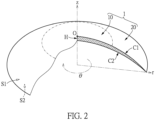
- an outer surface S 1 of the toric lens body 1 has a center O.
- the toric lens body 1 has radii extending outward from the center O along a radial direction.
- Cross sections of the toric lens body 1 are defined by the radii and the toric lens body 1 in a thickness direction, i.e., a z-axis direction shown in FIG. 2 .
- the cross section is an arc section.
- the arc section is a region formed by a first curve C1, a second curve C2, and a center section line H.
- a radius and the outer surface S 1 of the toric lens body 1 intersect with each other at the first curve C1, and a radius and an inner surface S2 of the toric lens body 1 intersect with each other at the second curve C2.
- the center section line H is formed by extending from the center O along the z-axis direction.
- FIG. 3 is a schematic enlarged schematic view of the arc section of FIG. 2 .
- the arc section covers the optical region 10 and the annular region 20 at the same time.
- the arc section includes an optical regional section A1 and an annular regional section A2.
- the optical regional section A1 is intersected by a radius along the thickness direction and the optical region 10
- the annular regional section A2 is intersected by a radius along the thickness direction and the annular region 20.
- ⁇ is an azimuth angle
- f( ⁇ ) is a polynomial, in which 0° ⁇ ⁇ ⁇ 360°, and 0.5 ⁇ P ⁇ 7.
- the area "A" of the arc section in the formula (I) is a sum of areas of the optical regional section A1 and the annular regional section A2.
- -10 -8 ⁇ a ⁇ -10 -9 , 10 -6 ⁇ b ⁇ 10 -5 , -10 -1 ⁇ c ⁇ -10 -4 , and 10 -4 ⁇ d ⁇ 10 -1 .
- f( ⁇ ) can be a trigonometric polynomial. According to experimental results, when the areas of the arc sections of the toric lens body 1 are designed based on the trigonometric polynomial, the contact lens thus obtained can be worn with comfort and has a rotation positioning effect.
- a maximum area of the arc section of the toric lens body 1 is adjusted according to "P - k1", and a minimum area of the arc section of the toric lens body 1 is adjusted according to "P - k2".
- a value of "k2" can be used to slightly adjust a difference between the areas of adjacent ones of the arc sections, such that an overall appearance of the toric lens body 1 can be smoother.
- the toric lens body 1 of the present invention is a ballast-designed contact lens.
- the optical region 10 of the toric lens body 1 can be obtained by integrating the optical regional section A1 according to an azimuth direction. Therefore, the structure of the optical region 10 can be obtained by designing the area of the optical regional section A1 at different azimuth angles ⁇ according to optometry data of a patient and then integrating the optical regional section A1 according to the azimuth direction.
- the structure of the toric lens body 1 can be designed by adjusting the area of the arc section, such that the influences of the optical region 10 and the annular region 20 on the overall structure of the toric lens body 1 are taken into consideration. Accordingly, a thickness difference formed on a boundary between the optical region 10 and the annular region 20 can be decreased.
- a thickness of the contact lens in the optical region 10 is great, such that the thickness difference is likely to occur on the boundary B1 at the top of the toric lens body 1 (i.e., the azimuth angle ⁇ is 0°).
- the thickness of the contact lens in the optical region 10 is thin, such that the thickness difference is likely to occur on the boundary B2 at the bottom of the toric lens body 1 (i.e., the azimuth angle ⁇ is 180°).
- Example 1 "P” is 2.5, k1 is 0.5, and k2 is 2, such that the formula (III) is represented by: 2.5 - [0.5sin( ⁇ /2) + 2cos 2 ( ⁇ /2)].
- the toric lens body 1 is demarcated into the optical region 10 and the annular region 20 as shown in FIG. 1 .
- the toric lens body 1 has radii extending outward from the center O along different azimuth angels ⁇ .
- the arc sections are defined by the radii and the toric lens body 1 in the thickness direction.
- the arc section includes the optical regional section A1 and the annular regional section A2.
- Example 1 the area of the optical regional section A1 is designed according to optometry data obtained with an astigmatism prescription of 0.0 diopters.
- the areas of the arc sections at different azimuth angles can be obtained by calculation of the formula (III).
- the areas of the arc sections at different azimuth angles are shown in FIG. 5 . It can be observed from FIG. 5 that the toric lens body 1 of Example 1 is a ballast-designed contact lens.
- the area of the annular regional section A2 is designed according to the optometry data and the design data. Since the arc section is formed by the optical regional section A1 and the annular regional section A2, the area of the annular regional section A2 can be obtained by subtracting the area of the optical regional section A1 from the area calculated by the formula (III).
- the optical regional section A1 and the annular regional section A2 can be merged into the arc section.
- the toric lens body 1 of Example 1 can be obtained by integrating the arc section along the azimuth direction.
- FIG. 6 to FIG. 8 are schematic views of the arc sections of the toric lens body 1 respectively at azimuth angles of 0°, 90°, and 180°. It can be observed from FIG. 6 to FIG. 8 that, when the azimuth angle increases, the area of the optical regional section A1 only slightly increases, but an increase of the area of the annular regional section A2 is more significant. In terms of the overall structure, the toric lens body 1 can still have a smooth appearance.
- Table 1 Azimuth angle 0° 90° 180° Area of the arc section 0.50 mm 2 1.15 mm 2 2.00 mm 2 Standardized areas of the arc section 1.00 2.30 4.00
- the thicknesses of the toric lens body 1 on an edge of the optical region 10 and on an edge of the annular region 20 are measured.
- the thickness difference and a thickness difference ratio are calculated.
- the thickness difference ratio is calculated by dividing the thickness difference at the boundaries B1, B2 between the optical region 10 and the annular region 20 by a thickness of the edge of the optical region 10. The specific thicknesses, the thickness difference, and the thickness difference ratio at the boundaries B1, B2 are listed in Table 2.
- Thickness of edge of optical region Thickness of edge of annular region
- Thickness difference ratio Boundary B1 110 ⁇ m 120 ⁇ m 10 ⁇ m 9%
- the thickness difference ratio at the boundaries B1, B2 between the optical region 10 and the annular region 20 of the toric lens body 1 of the present invention is lower than 150%, which is lower than the maximum thickness difference ratio (200%) of a conventional toric lens body. Since the areas of the optical region 10 and the annular region 20 are taken into consideration at the same time, the toric lens body 1 of the present invention has a good positioning effect and improved wearing comfort.
- the thickness difference ratio at the boundaries B1, B2 between the optical region 10 and the annular region 20 can be lower than 150%. More preferably, the thickness difference ratio at the boundaries B1, B2 between the optical region 10 and the annular region 20 can be lower than 100%. Even more preferably, the thickness difference ratio at the boundaries B1, B2 between the optical region 10 and the annular region 20 can be lower than 50% or even lower than 25%.
- the areas of the arc sections at azimuth angles of 0°, 90°, and 180° are calculated and listed in Table 4.
- the area of the arc section at an azimuth angle of 270° is the same as the area of the arc section at an azimuth angle of 90°, which will not be reiterated herein.
- the toric lens body 1 in Example 2 is similar to the toric lens body 1 in Example 1. The difference is that the area of the optical regional section A1 is designed according to optometry data obtained with an astigmatism prescription of 7.0 diopters.
- the area of the arc section at different azimuth angles can be obtained by calculation of the formula (III).
- the areas of the annular regional section A2 can be calculated according to the optometry data and the design data.
- the optical regional section A1 and the annular regional section A2 are merged and then integrated according to the azimuth direction, such that the toric lens body 1 in Example 2 can be obtained.
- the thicknesses of the toric lens body 1 at the boundary B1 i.e., the azimuth angle is 0°
- the boundary B2 i.e., the azimuth angle is 180°
- the specific thicknesses, the thickness difference, and the thickness difference ratio at the boundaries B1, B2 are listed in Table 3.
- Table 3 Thickness of Thickness of Thickness Thickness Thickness edge of optical region edge of annular region difference difference ratio
- the thickness difference ratio at the boundaries B1, B2 between the optical region 10 and the annular region 20 of the toric lens body 1 can be lower than 100%, which is lower than the maximum thickness difference ratio (110%) of the conventional toric lens body. Since the areas of the optical region 10 and the annular region 20 are taken into consideration at the same time, the toric lens body 1 can have a good positioning effect and improved wearing comfort.
- the thickness difference ratio at the boundaries B1, B2 between the optical region 10 and the annular region 20 of the toric lens body 1 can be lower than 75%. More preferably, the thickness difference ratio at the boundaries B1, B2 between the optical region 10 and the annular region 20 of the toric lens body 1 can be lower than 55%.
- the toric lens bodies 1 in Example 3 to 9 are similar to the toric lens body 1 in Example 1. The difference is that the parameters "P", "k1", and “k2" substituting into the formula (III) are different. Therefore, the areas of the arc sections (design data) in Examples 3 to 9 are different.
- the area ratio of the arc section at an azimuth angle of 180° to that at an azimuth angle of 0° ranges from 1.0 to 7.5.
- the area ratio of the arc section at an azimuth angle of 90° to that at an azimuth angle of 0° ranges from 1.0 to 4.5.
- the area ratio of the arc section at an azimuth angle of 180° to that at an azimuth angle of 90° ranges from 1.0 to 1.8.
- the toric lens bodies 1 in Example 10 to 12 are similar to the toric lens body 1 in Example 1. The difference is that the parameters "P”, “a”, “b”, “c” and “d” substituting into the formula (II) are different. Therefore, the areas of the arc sections (design data) in Examples 10 to 12 are different.
- the area ratio of the arc section at an azimuth angle of 180° to that at an azimuth angle of 0° ranges from 1.0 to 7.5.
- the area ratio of the arc section at an azimuth angle of 90° to that at an azimuth angle of 0° ranges from 1.0 to 4.5.
- the area ratio of the arc section at an azimuth angle of 180° to that at an azimuth angle of 90° ranges from 1.0 to 1.8.
- various polynomials such as the formula (II) or the formula (III)
- various contact lens can be obtained.
- the contact lens designed by a trigonometric polynomial such as the formula (III)
- the arc section defined by the toric lens body and the radius includes the optical regional section and the annular regional section.
- the area of the optical regional section can be selectively designed, and then the area of the annular regional section can be calculated according to the formula (I).
- the area of the annular regional section can be selectively designed, and then the area of the optical regional section can be calculated according to the formula (I).
- the contact lens of the present invention can have a good positioning effect and be worn with comfort.
Landscapes
- Health & Medical Sciences (AREA)
- Ophthalmology & Optometry (AREA)
- Physics & Mathematics (AREA)
- General Health & Medical Sciences (AREA)
- General Physics & Mathematics (AREA)
- Optics & Photonics (AREA)
- Eyeglasses (AREA)
- Lenses (AREA)
Applications Claiming Priority (1)
| Application Number | Priority Date | Filing Date | Title |
|---|---|---|---|
| TW112137280A TWI853722B (zh) | 2023-09-28 | 2023-09-28 | 隱形眼鏡 |
Publications (1)
| Publication Number | Publication Date |
|---|---|
| EP4530705A1 true EP4530705A1 (de) | 2025-04-02 |
Family
ID=90719250
Family Applications (1)
| Application Number | Title | Priority Date | Filing Date |
|---|---|---|---|
| EP24168920.7A Pending EP4530705A1 (de) | 2023-09-28 | 2024-04-08 | Kontaktlinse |
Country Status (5)
| Country | Link |
|---|---|
| US (1) | US20250110353A1 (de) |
| EP (1) | EP4530705A1 (de) |
| JP (1) | JP7759445B2 (de) |
| CN (1) | CN119717305A (de) |
| TW (1) | TWI853722B (de) |
Citations (5)
| Publication number | Priority date | Publication date | Assignee | Title |
|---|---|---|---|---|
| US20070146629A1 (en) * | 2005-12-22 | 2007-06-28 | Timothy Green | Toric contact lenses |
| US20190317337A1 (en) * | 2016-06-20 | 2019-10-17 | Hoya Corporation | Contact lens and method for manufacturing the same |
| US20190384072A1 (en) * | 2018-06-18 | 2019-12-19 | Johnson & Johnson Vision Care, Inc. | Rotationally stabilized contact lens with improved comfort and improved stabilization utilizing optimized stiffness profiles |
| EP2176702B1 (de) * | 2007-08-07 | 2020-07-08 | Alcon Inc. | Torische kontaktlinse mit verbessertem rückflächendesign |
| US20220334409A1 (en) * | 2019-09-25 | 2022-10-20 | Nthalmic Holding Pty Ltd | A contact lens solution for myopia management |
Family Cites Families (6)
| Publication number | Priority date | Publication date | Assignee | Title |
|---|---|---|---|---|
| US5650838A (en) * | 1995-05-04 | 1997-07-22 | Johnson & Johnson Vision Products, Inc. | Programmable smooth junctions on lenses |
| US6595640B1 (en) | 2000-11-15 | 2003-07-22 | Johnson & Johnson Vision Care, Inc. | Method for designing contact lenses |
| EP3391854A1 (de) * | 2006-01-12 | 2018-10-24 | Brien Holden Vision Institute | Verfahren und vorrichtung zur steuerung der peripheren bildposition zur verminderung von myopieprogression |
| DE102013216020A1 (de) * | 2013-08-13 | 2015-02-19 | Carl Zeiss Meditec Ag | Augenlinse mit einem torisch brechenden Oberflächenprofil und eine in radialer Richtung gestufte Oberflächenstruktur |
| CN112740099B (zh) * | 2018-07-30 | 2024-05-14 | 奥克塞拉有限公司 | 用于延缓近视进展的电子接触透镜的光学设计 |
| EP4104008A4 (de) * | 2020-02-14 | 2024-04-03 | Nthalmic Holding Pty Ltd | Freiform-kontaktlinsen für myopiemanagement |
-
2023
- 2023-09-28 TW TW112137280A patent/TWI853722B/zh active
-
2024
- 2024-03-18 CN CN202410307799.2A patent/CN119717305A/zh active Pending
- 2024-04-08 EP EP24168920.7A patent/EP4530705A1/de active Pending
- 2024-04-08 US US18/629,886 patent/US20250110353A1/en active Pending
- 2024-07-10 JP JP2024110662A patent/JP7759445B2/ja active Active
Patent Citations (5)
| Publication number | Priority date | Publication date | Assignee | Title |
|---|---|---|---|---|
| US20070146629A1 (en) * | 2005-12-22 | 2007-06-28 | Timothy Green | Toric contact lenses |
| EP2176702B1 (de) * | 2007-08-07 | 2020-07-08 | Alcon Inc. | Torische kontaktlinse mit verbessertem rückflächendesign |
| US20190317337A1 (en) * | 2016-06-20 | 2019-10-17 | Hoya Corporation | Contact lens and method for manufacturing the same |
| US20190384072A1 (en) * | 2018-06-18 | 2019-12-19 | Johnson & Johnson Vision Care, Inc. | Rotationally stabilized contact lens with improved comfort and improved stabilization utilizing optimized stiffness profiles |
| US20220334409A1 (en) * | 2019-09-25 | 2022-10-20 | Nthalmic Holding Pty Ltd | A contact lens solution for myopia management |
Also Published As
| Publication number | Publication date |
|---|---|
| TW202514209A (zh) | 2025-04-01 |
| US20250110353A1 (en) | 2025-04-03 |
| CN119717305A (zh) | 2025-03-28 |
| JP2025058893A (ja) | 2025-04-09 |
| TWI853722B (zh) | 2024-08-21 |
| JP7759445B2 (ja) | 2025-10-23 |
Similar Documents
| Publication | Publication Date | Title |
|---|---|---|
| EP0988574B2 (de) | Linse mit starker Krümmung für eine Brille | |
| US6334681B1 (en) | Lenses and spectacles bearing lenses | |
| US8042942B2 (en) | Progressive-power lens | |
| CN1232864C (zh) | 沿水平方向厚度分布均匀的贴目镜片 | |
| AU715443B2 (en) | Decentered noncorrective lens for eyewear | |
| US6789896B2 (en) | Shaped ophthalmic lenses | |
| US6199982B1 (en) | Presbyopia correction contact lens | |
| EP3105634B1 (de) | Quasi-progressive linsen für brillen | |
| CN114721167B (zh) | 低会聚眼镜 | |
| EP1158337B1 (de) | Multifokal-Linse mit progressiver Brechkraft | |
| CN106483676B (zh) | 具有改善舒适度的旋转稳定的接触镜片和优化方法 | |
| EP4530705A1 (de) | Kontaktlinse | |
| EP0379976A2 (de) | Asphärische ophthalmische Linse | |
| EP4513257A1 (de) | Linsenelement, gruppe optischer linsen, form und gläser | |
| EP0594848B1 (de) | Progressive linse | |
| JPH05215994A (ja) | 非球面眼鏡レンズ | |
| EP2940511A1 (de) | Multifokale sektorale ophthalmische Gleitsichtlinse | |
| JPH0812339B2 (ja) | 眼鏡レンズ | |
| CN113671723A (zh) | 角膜塑形镜 | |
| CN218601621U (zh) | 一种广角双光镜片元件 | |
| CN220872805U (zh) | 一种软硬镜片结合的近视防控隐形眼镜镜片 | |
| JP2001027744A (ja) | 非球面眼鏡レンズ | |
| CN121522905A (zh) | 一种近视防控复合离焦镜片 | |
| CN119072652A (zh) | 透镜元件、光学透镜组、模具及眼镜 | |
| CN118778287A (zh) | 透镜元件、模具及眼镜 |
Legal Events
| Date | Code | Title | Description |
|---|---|---|---|
| PUAI | Public reference made under article 153(3) epc to a published international application that has entered the european phase |
Free format text: ORIGINAL CODE: 0009012 |
|
| STAA | Information on the status of an ep patent application or granted ep patent |
Free format text: STATUS: THE APPLICATION HAS BEEN PUBLISHED |
|
| AK | Designated contracting states |
Kind code of ref document: A1 Designated state(s): AL AT BE BG CH CY CZ DE DK EE ES FI FR GB GR HR HU IE IS IT LI LT LU LV MC ME MK MT NL NO PL PT RO RS SE SI SK SM TR |
|
| STAA | Information on the status of an ep patent application or granted ep patent |
Free format text: STATUS: REQUEST FOR EXAMINATION WAS MADE |
|
| 17P | Request for examination filed |
Effective date: 20250910 |