EP4530701A2 - Baken zur lokalisierung und inhaltsbereitstellung an tragbare vorrichtungen - Google Patents
Baken zur lokalisierung und inhaltsbereitstellung an tragbare vorrichtungen Download PDFInfo
- Publication number
- EP4530701A2 EP4530701A2 EP25157272.3A EP25157272A EP4530701A2 EP 4530701 A2 EP4530701 A2 EP 4530701A2 EP 25157272 A EP25157272 A EP 25157272A EP 4530701 A2 EP4530701 A2 EP 4530701A2
- Authority
- EP
- European Patent Office
- Prior art keywords
- beacon
- eyewear
- location
- beacons
- display
- Prior art date
- Legal status (The legal status is an assumption and is not a legal conclusion. Google has not performed a legal analysis and makes no representation as to the accuracy of the status listed.)
- Pending
Links
Images


Classifications
-
- G—PHYSICS
- G06—COMPUTING OR CALCULATING; COUNTING
- G06T—IMAGE DATA PROCESSING OR GENERATION, IN GENERAL
- G06T19/00—Manipulating 3D models or images for computer graphics
- G06T19/006—Mixed reality
-
- H—ELECTRICITY
- H04—ELECTRIC COMMUNICATION TECHNIQUE
- H04W—WIRELESS COMMUNICATION NETWORKS
- H04W4/00—Services specially adapted for wireless communication networks; Facilities therefor
- H04W4/02—Services making use of location information
-
- G—PHYSICS
- G02—OPTICS
- G02B—OPTICAL ELEMENTS, SYSTEMS OR APPARATUS
- G02B27/00—Optical systems or apparatus not provided for by any of the groups G02B1/00 - G02B26/00, G02B30/00
- G02B27/01—Head-up displays
- G02B27/017—Head mounted
- G02B27/0172—Head mounted characterised by optical features
-
- G—PHYSICS
- G06—COMPUTING OR CALCULATING; COUNTING
- G06F—ELECTRIC DIGITAL DATA PROCESSING
- G06F16/00—Information retrieval; Database structures therefor; File system structures therefor
- G06F16/90—Details of database functions independent of the retrieved data types
- G06F16/95—Retrieval from the web
- G06F16/953—Querying, e.g. by the use of web search engines
- G06F16/9537—Spatial or temporal dependent retrieval, e.g. spatiotemporal queries
-
- G—PHYSICS
- G06—COMPUTING OR CALCULATING; COUNTING
- G06F—ELECTRIC DIGITAL DATA PROCESSING
- G06F3/00—Input arrangements for transferring data to be processed into a form capable of being handled by the computer; Output arrangements for transferring data from processing unit to output unit, e.g. interface arrangements
- G06F3/01—Input arrangements or combined input and output arrangements for interaction between user and computer
- G06F3/011—Arrangements for interaction with the human body, e.g. for user immersion in virtual reality
- G06F3/012—Head tracking input arrangements
-
- G—PHYSICS
- G06—COMPUTING OR CALCULATING; COUNTING
- G06F—ELECTRIC DIGITAL DATA PROCESSING
- G06F3/00—Input arrangements for transferring data to be processed into a form capable of being handled by the computer; Output arrangements for transferring data from processing unit to output unit, e.g. interface arrangements
- G06F3/01—Input arrangements or combined input and output arrangements for interaction between user and computer
- G06F3/03—Arrangements for converting the position or the displacement of a member into a coded form
- G06F3/033—Pointing devices displaced or positioned by the user, e.g. mice, trackballs, pens or joysticks; Accessories therefor
- G06F3/0354—Pointing devices displaced or positioned by the user, e.g. mice, trackballs, pens or joysticks; Accessories therefor with detection of 2D relative movements between the device, or an operating part thereof, and a plane or surface, e.g. 2D mice, trackballs, pens or pucks
- G06F3/03547—Touch pads, in which fingers can move on a surface
-
- G—PHYSICS
- G06—COMPUTING OR CALCULATING; COUNTING
- G06F—ELECTRIC DIGITAL DATA PROCESSING
- G06F3/00—Input arrangements for transferring data to be processed into a form capable of being handled by the computer; Output arrangements for transferring data from processing unit to output unit, e.g. interface arrangements
- G06F3/01—Input arrangements or combined input and output arrangements for interaction between user and computer
- G06F3/048—Interaction techniques based on graphical user interfaces [GUI]
- G06F3/0481—Interaction techniques based on graphical user interfaces [GUI] based on specific properties of the displayed interaction object or a metaphor-based environment, e.g. interaction with desktop elements like windows or icons, or assisted by a cursor's changing behaviour or appearance
- G06F3/0482—Interaction with lists of selectable items, e.g. menus
-
- G—PHYSICS
- G06—COMPUTING OR CALCULATING; COUNTING
- G06F—ELECTRIC DIGITAL DATA PROCESSING
- G06F3/00—Input arrangements for transferring data to be processed into a form capable of being handled by the computer; Output arrangements for transferring data from processing unit to output unit, e.g. interface arrangements
- G06F3/16—Sound input; Sound output
- G06F3/167—Audio in a user interface, e.g. using voice commands for navigating, audio feedback
-
- H—ELECTRICITY
- H04—ELECTRIC COMMUNICATION TECHNIQUE
- H04W—WIRELESS COMMUNICATION NETWORKS
- H04W4/00—Services specially adapted for wireless communication networks; Facilities therefor
- H04W4/02—Services making use of location information
- H04W4/023—Services making use of location information using mutual or relative location information between multiple location based services [LBS] targets or of distance thresholds
-
- H—ELECTRICITY
- H04—ELECTRIC COMMUNICATION TECHNIQUE
- H04W—WIRELESS COMMUNICATION NETWORKS
- H04W4/00—Services specially adapted for wireless communication networks; Facilities therefor
- H04W4/02—Services making use of location information
- H04W4/029—Location-based management or tracking services
-
- H—ELECTRICITY
- H04—ELECTRIC COMMUNICATION TECHNIQUE
- H04W—WIRELESS COMMUNICATION NETWORKS
- H04W4/00—Services specially adapted for wireless communication networks; Facilities therefor
- H04W4/20—Services signaling; Auxiliary data signalling, i.e. transmitting data via a non-traffic channel
-
- H—ELECTRICITY
- H04—ELECTRIC COMMUNICATION TECHNIQUE
- H04W—WIRELESS COMMUNICATION NETWORKS
- H04W8/00—Network data management
- H04W8/005—Discovery of network devices, e.g. terminals
-
- G—PHYSICS
- G02—OPTICS
- G02B—OPTICAL ELEMENTS, SYSTEMS OR APPARATUS
- G02B27/00—Optical systems or apparatus not provided for by any of the groups G02B1/00 - G02B26/00, G02B30/00
- G02B27/01—Head-up displays
- G02B27/0101—Head-up displays characterised by optical features
- G02B2027/0141—Head-up displays characterised by optical features characterised by the informative content of the display
-
- G—PHYSICS
- G02—OPTICS
- G02B—OPTICAL ELEMENTS, SYSTEMS OR APPARATUS
- G02B27/00—Optical systems or apparatus not provided for by any of the groups G02B1/00 - G02B26/00, G02B30/00
- G02B27/01—Head-up displays
- G02B27/017—Head mounted
- G02B2027/0178—Eyeglass type
-
- G—PHYSICS
- G06—COMPUTING OR CALCULATING; COUNTING
- G06F—ELECTRIC DIGITAL DATA PROCESSING
- G06F1/00—Details not covered by groups G06F3/00 - G06F13/00 and G06F21/00
- G06F1/16—Constructional details or arrangements
- G06F1/1613—Constructional details or arrangements for portable computers
- G06F1/163—Wearable computers, e.g. on a belt
-
- G—PHYSICS
- G06—COMPUTING OR CALCULATING; COUNTING
- G06T—IMAGE DATA PROCESSING OR GENERATION, IN GENERAL
- G06T2200/00—Indexing scheme for image data processing or generation, in general
- G06T2200/24—Indexing scheme for image data processing or generation, in general involving graphical user interfaces [GUIs]
-
- G—PHYSICS
- G10—MUSICAL INSTRUMENTS; ACOUSTICS
- G10L—SPEECH ANALYSIS TECHNIQUES OR SPEECH SYNTHESIS; SPEECH RECOGNITION; SPEECH OR VOICE PROCESSING TECHNIQUES; SPEECH OR AUDIO CODING OR DECODING
- G10L15/00—Speech recognition
- G10L15/26—Speech to text systems
Definitions
- Examples set forth in the present disclosure relate to the field of augmented reality experiences for electronic devices, including wearable devices such as eyewear. More particularly, but not by way of limitation, the present disclosure describes the use of beacons to localize wearable devices, to deliver relevant content, and to present virtual experiences in augmented reality.
- mobile devices e . g ., smartphones, tablets, and laptops
- wearable devices e . g ., smart glasses, digital eyewear, headwear, headgear, and head-mounted displays
- cameras sensors, wireless transceivers, input systems, and displays.
- Beacon transmitters are wireless transmitters that periodically broadcast a beacon that includes a unique identifier and one or more packets of data.
- Bluetooth or BLE beacons typically operate using the Bluetooth Low Energy (BLE) communications protocol.
- BLE Bluetooth Low Energy
- two or more beacons are coupled or attached to objects or fixed locations in a physical environment.
- a receiving device e.g., a mobile device, wearable device, or other smart device
- BLE beacons typically transmit information at a frequency of about 2.4 GHz, have a range of about three hundred feet, and operate on relatively low power ( e . g ., as low as ten milliwatts).
- data can be transmitted at a rate of up to two megabits per second (Mbit/s) with an application throughput of up to 1.37 Mbit/s.
- BLE messages are secured using encryption.
- Optical codes such as barcodes, QR codes, and MaxiCodes, are two-dimensional graphical images that contain encoded information readable by a camera or other optical sensor, such as those found in mobile devices, wearable devices, and other smart devices.
- Optical codes typically include one or more functional patterns (e.g., for identification, reading, and decoding the embedded information) along with non-functional elements or patterns (e.g., a logo, brand, trademark, trade dress, or other source identifier) to facilitate recognition by users.
- VR virtual reality
- AR Augmented reality
- XR Cross reality
- Graphical user interfaces allow the user to interact with displayed content, including virtual objects and graphical elements such as icons, taskbars, list boxes, menus, buttons, and selection control elements like cursors, pointers, handles, and sliders.
- virtual objects such as icons, taskbars, list boxes, menus, buttons, and selection control elements like cursors, pointers, handles, and sliders.
- ASR Automatic speech recognition
- ASR processing may be used by computers, handheld devices, wearable devices, telephone systems, automobiles, and a wide variety of other devices to facilitate human-computer interactions.
- beacon transmitters are programmed and deployed in a physical environment, such as an indoor space.
- the broadcast beacons are detected by an eyewear device, which uses the beacons to determine the current eyewear location and to retrieve relevant content.
- the retrieved content is used to present a virtual experience on the display of the eyewear as an overlay relative to the physical environment.
- Example methods include detecting a beacon broadcast by a beacon transmitter that is associated with a fixed beacon location in a physical environment.
- the beacon includes a unique identifier, beacon data, and a device certificate.
- the process in some examples includes determining whether the detected beacon satisfies a device certificate rule, and then determining the current eyewear location relative to the fixed beacon location ( e . g ., using one or more multilateration algorithms).
- the method includes retrieving content in accordance with the detected beacon.
- the retrieved content in some examples, is used to curate a virtual experience that is also based on the beacon data and a user profile.
- the method includes presenting the curated virtual experience on the display in accordance with the determined current eyewear location and as an overlay relative to the physical environment.
- the process of presenting the curated virtual experience includes playing an audio message through the loudspeaker, presenting text on the display, presenting a video segment on the display, and combinations thereof.
- Coupled refers to any logical, optical, physical, or electrical connection, including a link or the like by which the electrical or magnetic signals produced or supplied by one system element are imparted to another coupled or connected system element.
- coupled or connected elements or devices are not necessarily directly connected to one another and may be separated by intermediate components, elements, or communication media, one or more of which may modify, manipulate, or carry the electrical signals.
- on means directly supported by an element or indirectly supported by the element through another element that is integrated into or supported by the element.
- proximal is used to describe an item or part of an item that is situated near, adjacent, or next to an object or person; or that is closer relative to other parts of the item, which may be described as “distal.”
- distal the end of an item nearest an object
- the proximal end the end of an item nearest an object
- distal end the end of an item nearest an object
- the eyewear device may be oriented in any other direction suitable to the particular application of the eyewear device; for example, up, down, sideways, or any other orientation.
- any directional term such as front, rear, inward, outward, toward, left, right, lateral, longitudinal, up, down, upper, lower, top, bottom, side, horizontal, vertical, and diagonal are used by way of example only, and are not limiting as to the direction or orientation of any camera, inertial measurement unit, or display as constructed or as otherwise described herein.
- Advanced AR technologies such as computer vision and object tracking, may be used to produce a perceptually enriched and immersive experience.
- Computer vision algorithms extract three-dimensional data about the physical world from the data captured in digital images or video.
- Object recognition and tracking algorithms are used to detect an object in a digital image or video, estimate its orientation or pose, and track its movement over time. Hand and finger recognition and tracking in real time is one of the most challenging and processing-intensive tasks in the field of computer vision.
- pose refers to the static position and orientation of an object at a particular instant in time.
- gesture refers to the active movement of an object, such as a hand, through a series of poses, sometimes to convey a signal or idea.
- pose and gesture are sometimes used interchangeably in the field of computer vision and augmented reality.
- pose or gesture are intended to be inclusive of both poses and gestures; in other words, the use of one term does not exclude the other.
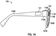
- FIG. 1A is a side view (right) of an example hardware configuration of an eyewear device 100 which includes a touch-sensitive input device such as a touchpad 181.
- the touchpad 181 may have a boundary that is plainly visible or include a raised or otherwise tactile edge that provides feedback to the user about the location and boundary of the touchpad 181 ; alternatively, the boundary may be subtle and not easily seen or felt.
- the eyewear device 100 may include a touchpad 181 on the left side that operates independently or in conjunction with a touchpad 181 on the right side.
- the surface of the touchpad 181 is configured to detect finger touches, taps, and gestures ( e . g ., moving touches) for use with a GUI displayed by the eyewear device, on an image display, to allow the user to navigate through and select menu options in an intuitive manner, which enhances and simplifies the user experience.
- Detection of finger inputs on the touchpad 181 can enable several functions. For example, touching anywhere on the touchpad 181 may cause the GUI to display or highlight an item on the image display, which may be projected onto at least one of the optical assemblies 180A, 180B. Tapping or double tapping on the touchpad 181 may select an item or icon. Sliding or swiping a finger in a particular direction ( e . g ., from front to back, back to front, up to down, or down to) may cause the items or icons to slide or scroll in a particular direction; for example, to move to a next item, icon, video, image, page, or slide. Sliding the finger in another direction may slide or scroll in the opposite direction; for example, to move to a previous item, icon, video, image, page, or slide.
- the touchpad 181 can be virtually anywhere on the eyewear device 100.
- an identified finger gesture of a single tap on the touchpad 181 initiates selection or pressing of a graphical user interface element in the image presented on the image display of the optical assembly 180A, 180B.
- An adjustment to the image presented on the image display of the optical assembly 180A, 180B based on the identified finger gesture can be a primary action which selects or submits the graphical user interface element on the image display of the optical assembly 180A, 180B for further display or execution.
- the eyewear device 100 includes a right visible-light camera 114B.
- two cameras 114A, 114B capture image information for a scene from two separate viewpoints. The two captured images may be used to project a three-dimensional display onto an image display for viewing with 3D glasses.
- the eyewear device 100 includes a right optical assembly 180B with an image display to present images, such as depth images. As shown in FIGS. 1A and 1B , the eyewear device 100 includes the right visible-light camera 114B.
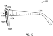
- the eyewear device 100 can include multiple visible-light cameras 114A, 114B that form a passive type of three-dimensional camera, such as stereo camera, of which the right visible-light camera 114B is located on a right corner 110B. As shown in FIGS. 1C-D , the eyewear device 100 also includes a left visible-light camera 114A.
- Left and right visible-light cameras 114A, 114B are sensitive to the visible-light range wavelength.
- Each of the visible-light cameras 114A, 114B have a different frontward facing field of view which are overlapping to enable generation of three-dimensional depth images, for example, right visible-light camera 114B depicts a right field of view 111B.
- a "field of view" is the part of the scene that is visible through the camera at a particular position and orientation in space.
- the fields of view 111A and 111B have an overlapping field of view 304 ( FIG. 3 ). Objects or object features outside the field of view 111A, 111B when the visible-light camera captures the image are not recorded in a raw image ( e .
- the field of view describes an angle range or extent, which the image sensor of the visible-light camera 114A, 114B picks up electromagnetic radiation of a given scene in a captured image of the given scene.
- Field of view can be expressed as the angular size of the view cone; i.e., an angle of view.
- the angle of view can be measured horizontally, vertically, or diagonally.
- one or both visible-light cameras 114A, 114B has a field of view of 100° and a resolution of 480 x 480 pixels.
- the "angle of coverage" describes the angle range that a lens of visible-light cameras 114A, 114B or infrared camera 410 (see FIG. 2A ) can effectively image.
- the camera lens produces an image circle that is large enough to cover the film or sensor of the camera completely, possibly including some vignetting ( e . g ., a darkening of the image toward the edges when compared to the center). If the angle of coverage of the camera lens does not fill the sensor, the image circle will be visible, typically with strong vignetting toward the edge, and the effective angle of view will be limited to the angle of coverage.
- Examples of such visible-light cameras 114A, 114B include a high-resolution complementary metal-oxide-semiconductor (CMOS) image sensor and a digital VGA camera (video graphics array) capable of resolutions of 480p ( e.g., 640 x 480 pixels), 720p, 1080p, or greater.
- CMOS complementary metal-oxide-semiconductor
- VGA camera video graphics array
- Other examples include visible-light cameras 114A, 114B that can capture high-definition (HD) video at a high frame rate (e . g ., thirty to sixty frames per second, or more) and store the recording at a resolution of 1216 by 1216 pixels (or greater).
- HD high-definition
- the eyewear device 100 may capture image sensor data from the visible-light cameras 114A, 114B along with geolocation data, digitized by an image processor, for storage in a memory.
- the visible-light cameras 114A, 114B capture respective left and right raw images in the two-dimensional space domain that comprise a matrix of pixels on a two-dimensional coordinate system that includes an X-axis for horizontal position and a Y-axis for vertical position.
- Each pixel includes a color attribute value (e.g., a red pixel light value, a green pixel light value, or a blue pixel light value); and a position attribute ( e . g ., an X-axis coordinate and a Y-axis coordinate).
- the image processor 412 may be coupled to the visible-light cameras 114A, 114B to receive and store the visual image information.
- the image processor 412 controls operation of the visible-light cameras 114A, 114B to act as a stereo camera simulating human binocular vision and may add a timestamp to each image.
- the timestamp on each pair of images allows display of the images together as part of a three-dimensional projection.
- Three-dimensional projections produce an immersive, life-like experience that is desirable in a variety of contexts, including virtual reality (VR) and video gaming.
- VR virtual reality
- FIG. 1B is a perspective, cross-sectional view of a right corner 110B of the eyewear device 100 of FIG. 1A depicting the right visible-light camera 114B of the camera system, and a circuit board.
- FIG. 1C is a side view (left) of an example hardware configuration of an eyewear device 100 of FIG. 1A , which shows a left visible-light camera 114A of the camera system.
- FIG. 1D is a perspective, cross-sectional view of a left corner 110A of the eyewear device of FIG. 1C depicting the left visible-light camera 114A of the three-dimensional camera, and a circuit board.
- the eyewear device 100 includes the right visible-light camera 114B and a circuit board 140B, which may be a flexible printed circuit board (PCB).
- a right hinge 126B connects the right corner 110B to a right temple 125B of the eyewear device 100.
- components of the right visible-light camera 114B, the flexible PCB 140B, or other electrical connectors or contacts may be located on the right temple 125B or the right hinge 126B.
- a left hinge 126A connects the left corner 110A to a left temple 125A of the eyewear device 100.
- components of the left visible-light camera 114A, the flexible PCB 140A, or other electrical connectors or contacts may be located on the left temple 125A or the left hinge 126A.
- the right corner 110B includes corner body 190 and a corner cap, with the corner cap omitted in the cross-section of FIG. 1B .
- various interconnected circuit boards such as PCBs or flexible PCBs, that include controller circuits for right visible-light camera 114B, microphone(s) 139, loudspeaker(s) 191, low-power wireless circuitry ( e . g ., for wireless short range network communication via Bluetooth TM ), high-speed wireless circuitry ( e . g ., for wireless local area network communication via Wi-Fi).
- the right visible-light camera 114B is coupled to or disposed on the flexible PCB 140B and covered by a visible-light camera cover lens, which is aimed through opening(s) formed in the frame 105.
- a visible-light camera cover lens which is aimed through opening(s) formed in the frame 105.
- the right rim 107B of the frame 105 shown in FIG. 2A , is connected to the right corner 110B and includes the opening(s) for the visible-light camera cover lens.
- the frame 105 includes a front side configured to face outward and away from the eye of the user.
- the opening for the visible-light camera cover lens is formed on and through the front or outward-facing side of the frame 105.
- the right visible-light camera 114B has an outward-facing field of view 111B (shown in FIG.
- the visible-light camera cover lens can also be adhered to a front side or outward-facing surface of the right corner 110B in which an opening is formed with an outward-facing angle of coverage, but in a different outwardly direction.
- the coupling can also be indirect via intervening components.
- FIG. 2A is an example hardware configuration for the eyewear device 100 in which the right corner 110B supports a microphone 139 and a loudspeaker 191.
- the microphone 139 includes a transducer that converts sound into a corresponding electrical audio signal.
- the microphone 139 in this example, as shown, is positioned with an opening that faces inward toward the wearer, to facilitate reception of the sound waves, such as human speech including verbal commands and questions. Additional or differently oriented openings may be implemented.
- the eyewear device 100 is coupled to one or more microphones 139, configured to operate together or independently, and positioned at various locations on the eyewear device 100.
- the prism can optionally be sized and shaped to magnify the image projected by the display matrix 177, and the light travels through the prism so that the image viewed from the second surface is larger in one or more dimensions than the image emitted from the display matrix 177.
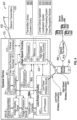
- the example content delivery system 400 is coupled to a transmitter library 480 and a content library 482.
- the eyewear device 100 is coupled to or otherwise in communication with the libraries 480, 482.
- the content library 482 stores data about each of a content items (e.g., text, audio files, video segments).
- the data record for each item of content may include a name, a unique identifier, a category or topic, and a variety of other information that would be useful in cataloguing and retrieving the content.
- the content is stored and maintained for easy access and use when the system retrieves content associated with a detected beacon 630.
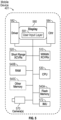
- FIG. 5 is a high-level functional block diagram of an example mobile device 401.
- Mobile device 401 includes a flash memory 540A which stores programming to be executed by the CPU 530 to perform all or a subset of the functions described herein.
- the mobile device 401 may include a camera 570 that comprises at least two visible-light cameras (first and second visible-light cameras with overlapping fields of view) or at least one visible-light camera and a depth sensor with substantially overlapping fields of view. Flash memory 540A may further include multiple images or video, which are generated via the camera 570.
- the mobile device 401 includes an image display 580, a mobile display driver 582 to control the image display 580, and a display controller 584.
- the image display 580 includes a user input layer 591 (e.g., a touchscreen) that is layered on top of or otherwise integrated into the screen used by the image display 580.
- FIG. 5 therefore provides a block diagram illustration of the example mobile device 401 with a user interface that includes a touchscreen input layer 591 for receiving input (by touch, multi-touch, or gesture, and the like, by hand, stylus, or other tool) and an image display 580 for displaying content
- the mobile device 401 includes at least one digital transceiver (XCVR) 510, shown as WWAN XCVRs, for digital wireless communications via a wide-area wireless mobile communication network.
- the mobile device 401 also includes additional digital or analog transceivers, such as short-range transceivers (XCVRs) 520 for short-range network communication, such as via NFC, VLC, DECT, ZigBee, Bluetooth TM , or Wi-Fi.
- short range XCVRs 520 may take the form of any available two-way wireless local area network (WLAN) transceiver of a type that is compatible with one or more standard protocols of communication implemented in wireless local area networks, such as one of the Wi-Fi standards under IEEE 802.11.
- WLAN wireless local area network
- the client device 401 in some examples includes a collection of motion-sensing components referred to as an inertial measurement unit (IMU) 572 for sensing the position, orientation, and motion of the client device 401.
- the motion-sensing components may be micro-electro-mechanical systems (MEMS) with microscopic moving parts, often small enough to be part of a microchip.
- the inertial measurement unit (IMU) 572 in some example configurations includes an accelerometer, a gyroscope, and a magnetometer.
- the accelerometer senses the linear acceleration of the client device 401 (including the acceleration due to gravity) relative to three orthogonal axes (x, y, z).
- the IMU 572 may include or cooperate with a digital motion processor or programming that gathers the raw data from the components and compute a number of useful values about the position, orientation, and motion of the client device 401.
- the acceleration data gathered from the accelerometer can be integrated to obtain the velocity relative to each axis (x, y, z); and integrated again to obtain the position of the client device 401 (in linear coordinates, x, y, and z).
- the angular velocity data from the gyroscope can be integrated to obtain the position of the client device 401 (in spherical coordinates).
- the programming for computing these useful values may be stored in on or more memory elements 540A, 540B, 540C and executed by the CPU 530 of the client device 401.
- the transceivers 510, 520 conforms to one or more of the various digital wireless communication standards utilized by modern mobile networks.
- WWAN transceivers 510 include (but are not limited to) transceivers configured to operate in accordance with Code Division Multiple Access (CDMA) and 3rd Generation Partnership Project (3GPP) network technologies including, for example and without limitation, 3GPP type 2 (or 3GPP2) and LTE, at times referred to as "4G.”
- CDMA Code Division Multiple Access
- 3GPP 3rd Generation Partnership Project
- 3GPP type 2 or 3GPP2
- LTE Long Term Evolution
- the transceivers 510, 520 provide two-way wireless communication of information including digitized audio signals, still image and video signals, web page information for display as well as web-related inputs, and various types of mobile message communications to/from the mobile device 401.
- the mobile device 401 further includes a microprocessor that functions as a central processing unit (CPU); shown as CPU 530 in FIG. 4 .
- a processor is a circuit having elements structured and arranged to perform one or more processing functions, typically various data processing functions. Although discrete logic components could be used, the examples utilize components forming a programmable CPU.
- a microprocessor for example includes one or more integrated circuit (IC) chips incorporating the electronic elements to perform the functions of the CPU.
- the CPU 530 may be based on any known or available microprocessor architecture, such as a Reduced Instruction Set Computing (RISC) using an ARM architecture, as commonly used today in mobile devices and other portable electronic devices. Of course, other arrangements of processor circuitry may be used to form the CPU 530 or processor hardware in smartphone, laptop computer, and tablet.
- RISC Reduced Instruction Set Computing
- the CPU 530 serves as a programmable host controller for the mobile device 401 by configuring the mobile device 401 to perform various operations, for example, in accordance with instructions or programming executable by CPU 530.
- operations may include various general operations of the mobile device, as well as operations related to the programming for applications on the mobile device.
- a processor may be configured by use of hardwired logic, typical processors in mobile devices are general processing circuits configured by execution of programming.
- the mobile device 401 includes a memory or storage system, for storing programming and data.
- the memory system may include a flash memory 540A, a random-access memory (RAM) 540B, and other memory components 540C, as needed.
- the RAM 540B serves as short-term storage for instructions and data being handled by the CPU 530, e.g., as a working data processing memory.
- the flash memory 540A typically provides longer-term storage.
- the flash memory 540A is used to store programming or instructions for execution by the CPU 530.
- the mobile device 401 stores and runs a mobile operating system through which specific applications are executed. Examples of mobile operating systems include Google Android, Apple iOS (for iPhone or iPad devices), Windows Mobile, Amazon Fire OS, RIM BlackBerry OS, or the like.
- the processor 432 within the eyewear device 100 may construct a map of the environment surrounding the eyewear device 100, determine a location of the eyewear device within the mapped environment, and determine a relative position of the eyewear device to one or more objects in the mapped environment.
- the processor 432 may construct the map and determine location and position information using a simultaneous localization and mapping (SLAM) algorithm applied to data received from one or more sensors.
- Sensor data includes images received from one or both of the cameras 114A, 114B, distance(s) received from a laser range finder, position information received from a GPS unit, motion and acceleration data received from an IMU 572, or a combination of data from such sensors, or from other sensors that provide data useful in determining positional information.
- SLAM simultaneous localization and mapping
- a SLAM algorithm is used to construct and update a map of an environment, while simultaneously tracking and updating the location of a device (or a user) within the mapped environment.
- the mathematical solution can be approximated using various statistical methods, such as particle filters, Kalman filters, extended Kalman filters, and covariance intersection.
- the SLAM algorithm updates the map and the location of objects at least as frequently as the frame rate; in other words, calculating and updating the mapping and localization thirty times per second.
- Sensor data includes image(s) received from one or both cameras 114A, 114B, distance(s) received from a laser range finder, position information received from a GPS unit, motion and acceleration data received from an IMU 472, or a combination of data from such sensors, or from other sensors that provide data useful in determining positional information.
- FIG. 6 depicts an example physical environment 600 along with elements that are useful when using a SLAM application and other types of tracking applications (e . g ., natural feature tracking (NFT)).
- a user 602 of eyewear device 100 is present in an example physical environment 600 (which, in FIG. 6 , is an interior room).
- the processor 432 of the eyewear device 100 determines its position with respect to one or more objects 604 within the environment 600 using captured images, constructs a map of the environment 600 using a coordinate system (x, y, z) for the environment 600, and determines its position within the coordinate system. Additionally, the processor 432 determines a head pose (roll, pitch, and yaw) of the eyewear device 100 within the environment by using two or more location points ( e .
- the processor 432 of the eyewear device 100 may position a virtual object 608 (such as the key shown in FIG. 6 ) within the environment 600 for viewing during an augmented reality experience.
- the localization system 915 in some examples a virtual marker 610a associated with a virtual object 608 in the environment 600.
- markers are registered at locations in the environment to assist devices with the task of tracking and updating the location of users, devices, and objects (virtual and physical) in a mapped environment. Markers are sometimes registered to a high-contrast physical object, such as the relatively dark object, such as the framed picture 604a, mounted on a lighter-colored wall, to assist cameras and other sensors with the task of detecting the marker.
- the markers may be preassigned or may be assigned by the eyewear device 100 upon entering the environment.
- Markers can be encoded with or otherwise linked to information.
- a marker might include position information, a physical code (such as a bar code or a QR code; either visible to the user or hidden), or a combination thereof.
- a set of data associated with the marker is stored in the memory 434 of the eyewear device 100.
- the set of data includes information about the marker 610a, the marker's position (location and orientation), one or more virtual objects, or a combination thereof.
- the marker position may include three-dimensional coordinates for one or more marker landmarks 616a, such as the corner of the generally rectangular marker 610a shown in FIG. 6 .
- the marker location may be expressed relative to real-world geographic coordinates, a system of marker coordinates, a position of the eyewear device 100, or other coordinate system.
- the one or more virtual objects associated with the marker 610a may include any of a variety of material, including still images, video, audio, tactile feedback, executable applications, interactive user interfaces and experiences, and combinations or sequences of such material. Any type of content capable of being stored in a memory and retrieved when the marker 610a is encountered or associated with an assigned marker may be classified as a virtual object in this context.
- the key 608 shown in FIG. 6 is a virtual object displayed as a still image, either 2D or 3D, at a marker location.
- the marker 610a may be registered in memory as being located near and associated with a physical object 604a (e.g., the framed work of art shown in FIG. 6 ). In another example, the marker may be registered in memory as being a particular position with respect to the eyewear device 100.
- FIG. 8 is a flow chart 820 listing the steps in an example method of presenting a virtual experience 700 on the display 180B of an eyewear device 100.
- steps are described with reference to the eyewear device 100 described herein, other implementations of the steps described, for other types of devices, will be understood by one of skill in the art from the description herein.
- One or more of the steps shown and described may be performed simultaneously, in a series, in an order other than shown and described, or in conjunction with additional steps. Some steps may be omitted or, in some applications, repeated.
- the content delivery application 910 described herein starts in response to receiving a selection through a user interface (e . g ., selecting from a menu, pressing a button, using a touchpad) or through some other input means (e . g ., hand gesture, finger motion, voice command). In other examples, the content delivery application 910 starts in response to detecting a beacon 630 as described herein.
- a user interface e . g ., selecting from a menu, pressing a button, using a touchpad
- some other input means e . g ., hand gesture, finger motion, voice command.
- the content delivery application 910 starts in response to detecting a beacon 630 as described herein.
- Block 822 in FIG. 8 describes an example step of detecting a beacon 630 with the wireless communications circuitry 420, 430 of an eyewear device 100.
- the beacon 630 in this example is broadcast by a beacon transmitter 620 associated with a fixed beacon location 720 in a physical environment 600.
- a beacon transmitter 620 may be located near an object 650 ( e.g., an exhibit, a work of art, an article of merchandise).
- the beacon 630 in some implementations includes a unique identifier 631, beacon data 632, and a device certificate 633.
- the eyewear device 100 in this example includes a camera 114B, a loudspeaker 191, a content delivery application 910, a localization system 915, and a display 180B.
- the process of detecting beacons 630 is ongoing during active use of the eyewear device 100. In other examples, the process of detecting beacons 630 starts in response to receiving a selection through a user interface or through some other input means.
- the example step at block 822 includes storing the captured beacons 630 in memory 434 on the eyewear device 100, at least temporarily, such that the captured beacons 630 are available for analysis.
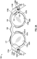
- FIG. 7 is a perspective illustration of an example arrangement of beacon transmitters 620a, 620b along with a virtual experience 700 presented on a display 180 B.
- the physical environment 600 includes a first object 650 a, a first beacon transmitter 620 a located at a fixed beacon location 702 a.
- the first beacon transmitter 620 a is associated with the first object 650 a .
- a first beacon activation code 655 a which is located at a fixed position relative to the fixed beacon location 702 a.
- the beacon activation code 655 a in some implementations is an optical code that contains encoded information readable by the camera 114 B of the eyewear device 100.
- a second or subsequent object 650 b also shown in FIG. 7 is a second or subsequent object 650 b, a subsequent beacon transmitter 620 b located at a subsequent fixed beacon location 702 b, and a subsequent beacon activation code 655 b.
- the physical environment 600 may include a plurality of objects 650 , each associated with its own beacon transmitter 620 and activation code 655.
- an object 650 may be an exhibit, a work of art, an item of merchandise, a menu, or any other item.
- the content delivery application 910 is configured to detect and act upon a certain subset of beacons which satisfy a device certificate rule 805.
- a device certificate rule 805 For example, when an owner or operator programs the beacon transmitters 620 for installation in a particular physical environment 600 (e.g., a retail store, a gallery, a museum), the beacon 630 is configured to include a device certificate 633 that acts as a source identifier.
- the device certificate 633 may include a unique numerical or text identifier (e . g ., Mobile App, Macy's, MOMA).
- the device certificate rule 805 requires that only beacons 630 having a particular device certificate 633 (e.g., Mobile App) will be detected and used.
- the content delivery application 910 is configured to detect only those beacons 630 which are programmed with a device certificate 633 that includes "Mobile App.” Other beacons with different device certificates will be ignored.
- block 824 in FIG. 8 describes an example step of determining, with the localization system 915 and based on the detected beacon 630, a current eyewear location 840 relative to the fixed beacon location 720.
- the beacons 630 broadcast by the beacon transmitters 620 are used to calculate or otherwise determine the current eyewear location 840 relative to the fixed beacon locations 720.
- the signal strength of a beacon 630 varies according to distance. The greater the distance from the beacon transmitter 620, the lower the signal strength.
- the beacon 630 in some implementations is calibrated by the manufacturer to have a design signal strength at a known distance ( e . g ., one meter away from the beacon transmitter 620 ).
- the receiving device e.g., an eyewear device 100
- the receiving device is configured to detect the actual signal strength, measured at the instant when the beacon 630 is received. Using the design signal strength and the actual signal strength, the receiving device can approximate the distance between the beacon transmitter 620 and the receiving device (based on a single beacon 630).
- the receiving device in some implementations is configured to measure the actual received signal strength associated with each beacon 630. For example, referring again to FIG. 7 , the first beacon transmitter 620 a broadcasts a first beacon 630 a which arrives at the eyewear device 100 having a first received signal strength 640 a. A second or subsequent beacon transmitter 620 b broadcasts a second beacon 630 b which arrives at the eyewear device 100 having subsequent received signal strength 640 b.
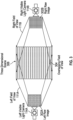
- the localization system 915 on the eyewear device 100 uses one or more three-dimensional multilateration algorithms (sometimes referred to as triangulation or trilateration) to compute the precise current eyewear location 840 relative to the two fixed beacon locations 720 a, 720 b.
- three-dimensional multilateration algorithms sometimes referred to as triangulation or trilateration
- the localization system 915 does not use data from the GPS unit and does not construct a virtual map using a SLAM algorithm, as described herein.
- the beacons 630 which are broadcast relatively frequently (e . g ., ten times per second, or more)
- the localization system 915 calculates and updates the current eyewear location 840 continually and frequently.
- the current eyewear location 840 is shared with an application capable of generating an interactive map of the nearby physical environment 600.
- the map application in this example presents the current eyewear location 840 on the display 180 B as an overlay (e.g., a blue dot, a marker) relative to other features of the map.
- the process of localization includes calculating a correlation between the detected beacon transmitters 620 and the current eyewear location 840.
- the term correlation refers to and includes one or more vectors, matrices, formulas, or other mathematical expressions sufficient to define the three-dimensional distance between one or more of the detected beacon transmitters 620 and the eyewear display 180B, in accordance with the current eyewear location 840.
- the current eyewear location 840 is tied to or persistently associated with the display 180B which is supported by the frame of the eyewear device 100.
- the correlation performs the function of calibrating the motion of the eyewear 100 through the physical environment 600 with the apparent motion of the detected beacon transmitters 620 (relative to the eyewear 100 ). Because the localization process occurs continually and frequently, the correlation is calculated continually and frequently, resulting in accurate and near real-time tracking of the detected beacon transmitters 620 relative to the current eyewear location 840.
- Block 826 in FIG. 8 describes an example step of retrieving content 800 associated with the detected beacon 630.
- the process of retrieving content 800 includes accessing one or more sources of information.
- the content 800 may be retrieved from the data 632 contained in the detected beacon 630 itself, from information stored in a content library 482, from local content stored on the eyewear device 100, or in some implementations from internet search results.
- the process in this example includes assembling search terms, executing a search, and harvesting content relevant to the detected beacon 630.
- the content delivery application 910 in some implementations, is configured to access one or more preferred search engines, websites, and other internet-based resources.
- the process of retrieving content 880 using an internet search involves using a machine-learning algorithm to select the search engine, web resources, and website data most likely to retrieve relevant container information quickly and efficiently.
- the detected beacon 630 includes an activator or trigger which causes the content delivery application 910 to retrieve content 800 from one or more available sources.
- Block 828 in FIG. 8 describes an example step of curating a virtual experience 700 in accordance with the retrieved content 800, the beacon data 632, and a user profile 880.
- the process of curating in some implementations includes simply presenting substantially all of the retrieved content 800 ( e.g., text, audio files, video segments) or the beacon data 632.
- the beacon data 632 as described herein, may include one or more items of relevant content ( e . g ., text, audio files, video segments) suitable for presentation.
- the user profile 880 in some implementations includes one or more elements, such as a primary interest ( e .
- the process of curating the virtual experience 700 includes consideration of the elements of the user profile 880.
- the retrieved content 800 may include a wide variety of food items on the menu. If the user profile 800 includes "vegetarian food" as a primary interest, the process of curating the virtual experience 700 may include presenting the vegetarian food items first or exclusively.
- Block 830 in FIG. 8 describes an example step of presenting the curated virtual experience 700 on the display 180 B in accordance with the determined current eyewear location 840.
- one or more elements of the curated virtual experience 700 may be sized and positioned on the display 180 B according to the current eyewear location 840.
- the process of presenting the curated virtual experience 700 may include playing an audio message through the loudspeaker 191, presenting text on the display, presenting a video segment on the display, and combinations thereof.
- FIG. 7 include an example region or sector 710 of the display 180 B which is suitable for presenting text, video, or other elements of the curated virtual experience 700.
- the sector 710 is located at a sector position 730 that is fixed relative to the display 180 B ( e . g ., presented along the left side).
- the size and shape of the sector 710 is editable, configurable, dynamic in response to the size and shape of the content to be presented, or combinations thereof.
- the process includes presenting the curated virtual experience 700 on a second eyewear device, a mobile device (e.g., a smartphone, tablet), or another designated device.
- Block 832 in FIG. 8 describes an example step of identifying a primary beacon 645 based on the relative proximity of two or more beacons 630 relative to the current eyewear location 840.
- the first or detected beacon 630 a arrives at the eyewear device 100 having a first received signal strength 640 a.
- a second or subsequent beacon 630 b arrives at the eyewear device 100 having subsequent received signal strength 640 b .
- the process of identifying a primary beacon 645 in this example includes comparing the two received signal strengths 640 a, 640 b and selecting the higher value (which represents the beacon transmitter closest in proximity to the current eyewear location 840 ).
- Block 834 in FIG. 8 describes an example step of detecting a beacon 630 which, in some implementations, includes scanning and decoding a beacon activation code 655 instead of detecting the beacon wirelessly.
- the camera 114 B can be used to scan and decode a beacon activation code 655.
- a first beacon activation code 655 a is associated with the first beacon transmitter 720 a and is located at a fixed location relative to the fixed beacon location 702 a.
- the process of detecting the first beacon 630 a in this example includes capturing frames of video data 900 within a field of view 904 of the camera 114 B, decoding (within the captured frames of video data 900 ) the first beacon activation code 655 a, and in response detecting the first beacon 630 a .
- the process of decoding the first beacon activation code 655 a provokes the selection of the first beacon 630 a .
- Block 836 in FIG. 8 describes an example step of detecting a beacon by making a selection from a list.
- the first beacon transmitter 620 a is associated with a first object 650 a .
- the second or subsequent beacon transmitter 620 b is associated with a second object 650 b .
- this process includes presenting a list 865 within a sector 710 located at a sector position 730 on the display 180 B.
- the list 865 includes the first object 650 a and the subsequent object 650 b, in order based on relative proximity to the determined current eyewear location 840 ( e.g., the object 650 associated with the nearest beacon transmitter 620 is shown first).
- the process in this example includes receiving a selection 870 from the displayed list 865 , and then detecting the beacon 630 in accordance with the received selection 870.
- the process of receiving a selection 870 includes detecting a tapping gesture on a touchpad 181, processing a voice command using a voice recognition module, executing the selection in response to a predefined hand gesture detected within frames of video data 900 captured by the camera 114 B, and combinations thereof.
- the example eyewear device 100 includes a touchpad 181 located on the right temple 125B.
- a movable element 711 e.g., a cursor, as shown in FIG. 7
- Interacting with the cursor 711 includes detecting a current fingertip location 681 relative to the touchpad 181, and then presenting the cursor 711 at a current element position 740 in accordance with the detected current fingertip location 681.
- the selection process in this example includes identifying a first item on the presented list 865 that is nearest to the current element position 740 , detecting a tapping gesture of the finger relative to the touchpad 181, and then executing the selection 870 relative to the first item in accordance with the detected tapping gesture.
- the process of receiving a selection 870 includes receiving human speech through a microphone 139 coupled to the eyewear device 100, as shown in FIG. 7 , and then converting the speech into frames of audio data 905.
- the voice recognition module 925 analyzes the frames of audio data 905, using automated speech recognition processing, to identify a first command 860.
- the process in this example includes executing the selection 870 relative to the first item in accordance with the first command 760.
- the automated speech recognition involves using a machine-learning algorithm that has been trained to detect, decipher, and identify the contents of human speech quickly and efficiently.
- any of the functionality described herein for the eyewear device 100 , the mobile device 401, and the server system 498 can be embodied in one or more computer software applications or sets of programming instructions, as described herein.
- "function,” “functions,” “application,” “applications,” “instruction,” “instructions,” or “programming” are program(s) that execute functions defined in the programs.
- Various programming languages can be employed to develop one or more of the applications, structured in a variety of manners, such as object-oriented programming languages (e . g ., Objective-C, Java, or C++) or procedural programming languages ( e.g., C or assembly language).
- object-oriented programming languages e. g ., Objective-C, Java, or C++
- procedural programming languages e.g., C or assembly language
- a third-party application e .
- an application developed using the ANDROID TM or IOS TM software development kit (SDK) by an entity other than the vendor of the particular platform) may include mobile software running on a mobile operating system such as IOS TM , ANDROID TM , WINDOWS ® Phone, or another mobile operating system.
- the third-party application can invoke API calls provided by the operating system to facilitate functionality described herein.
- Non-volatile storage media include, for example, optical or magnetic disks, such as any of the storage devices in any computer devices or the like, such as may be used to implement the client device, media gateway, transcoder, etc. shown in the drawings.
- Volatile storage media include dynamic memory, such as main memory of such a computer platform.
- Tangible transmission media include coaxial cables; copper wire and fiber optics, including the wires that comprise a bus within a computer system.
- Carrier-wave transmission media may take the form of electric or electromagnetic signals, or acoustic or light waves such as those generated during radio frequency (RF) and infrared (IR) data communications.
- Computer-readable media therefore include for example: a floppy disk, a flexible disk, hard disk, magnetic tape, any other magnetic medium, a CD-ROM, DVD or DVD-ROM, any other optical medium, punch cards paper tape, any other physical storage medium with patterns of holes, a RAM, a PROM and EPROM, a FLASH-EPROM, any other memory chip or cartridge, a carrier wave transporting data or instructions, cables or links transporting such a carrier wave, or any other medium from which a computer may read programming code or data. Many of these forms of computer readable media may be involved in carrying one or more sequences of one or more instructions to a processor for execution.
- any and all measurements, values, ratings, positions, magnitudes, sizes, and other specifications that are set forth in this specification, including in the claims that follow, are approximate, not exact. Such amounts are intended to have a reasonable range that is consistent with the functions to which they relate and with what is customary in the art to which they pertain. For example, unless expressly stated otherwise, a parameter value or the like may vary by as much as plus or minus ten percent from the stated amount or range.
Landscapes
- Engineering & Computer Science (AREA)
- Theoretical Computer Science (AREA)
- General Engineering & Computer Science (AREA)
- Physics & Mathematics (AREA)
- General Physics & Mathematics (AREA)
- Human Computer Interaction (AREA)
- Databases & Information Systems (AREA)
- Computer Networks & Wireless Communication (AREA)
- Signal Processing (AREA)
- Health & Medical Sciences (AREA)
- Multimedia (AREA)
- Audiology, Speech & Language Pathology (AREA)
- General Health & Medical Sciences (AREA)
- Computer Graphics (AREA)
- Computer Hardware Design (AREA)
- Software Systems (AREA)
- Data Mining & Analysis (AREA)
- Optics & Photonics (AREA)
- Computational Linguistics (AREA)
- Acoustics & Sound (AREA)
- User Interface Of Digital Computer (AREA)
- Information Transfer Between Computers (AREA)
Applications Claiming Priority (3)
| Application Number | Priority Date | Filing Date | Title |
|---|---|---|---|
| US202163190663P | 2021-05-19 | 2021-05-19 | |
| PCT/US2022/029550 WO2022245765A1 (en) | 2021-05-19 | 2022-05-17 | Beacons for localization and content delivery to wearable devices |
| EP22733782.1A EP4342196B1 (de) | 2021-05-19 | 2022-05-17 | Baken zur lokalisierung und inhaltsbereitstellung an tragbare vorrichtungen |
Related Parent Applications (1)
| Application Number | Title | Priority Date | Filing Date |
|---|---|---|---|
| EP22733782.1A Division EP4342196B1 (de) | 2021-05-19 | 2022-05-17 | Baken zur lokalisierung und inhaltsbereitstellung an tragbare vorrichtungen |
Publications (2)
| Publication Number | Publication Date |
|---|---|
| EP4530701A2 true EP4530701A2 (de) | 2025-04-02 |
| EP4530701A3 EP4530701A3 (de) | 2025-06-11 |
Family
ID=82214174
Family Applications (2)
| Application Number | Title | Priority Date | Filing Date |
|---|---|---|---|
| EP25157272.3A Pending EP4530701A3 (de) | 2021-05-19 | 2022-05-17 | Baken zur lokalisierung und inhaltsbereitstellung an tragbare vorrichtungen |
| EP22733782.1A Active EP4342196B1 (de) | 2021-05-19 | 2022-05-17 | Baken zur lokalisierung und inhaltsbereitstellung an tragbare vorrichtungen |
Family Applications After (1)
| Application Number | Title | Priority Date | Filing Date |
|---|---|---|---|
| EP22733782.1A Active EP4342196B1 (de) | 2021-05-19 | 2022-05-17 | Baken zur lokalisierung und inhaltsbereitstellung an tragbare vorrichtungen |
Country Status (5)
| Country | Link |
|---|---|
| US (3) | US11699271B2 (de) |
| EP (2) | EP4530701A3 (de) |
| KR (1) | KR20240009999A (de) |
| CN (1) | CN117356116A (de) |
| WO (1) | WO2022245765A1 (de) |
Families Citing this family (110)
| Publication number | Priority date | Publication date | Assignee | Title |
|---|---|---|---|---|
| US10509466B1 (en) | 2011-05-11 | 2019-12-17 | Snap Inc. | Headwear with computer and optical element for use therewith and systems utilizing same |
| US10439972B1 (en) | 2013-05-30 | 2019-10-08 | Snap Inc. | Apparatus and method for maintaining a message thread with opt-in permanence for entries |
| US9276886B1 (en) | 2014-05-09 | 2016-03-01 | Snapchat, Inc. | Apparatus and method for dynamically configuring application component tiles |
| US9537811B2 (en) | 2014-10-02 | 2017-01-03 | Snap Inc. | Ephemeral gallery of ephemeral messages |
| US10775996B2 (en) | 2014-11-26 | 2020-09-15 | Snap Inc. | Hybridization of voice notes and calling |
| US9385983B1 (en) | 2014-12-19 | 2016-07-05 | Snapchat, Inc. | Gallery of messages from individuals with a shared interest |
| KR102035405B1 (ko) | 2015-03-18 | 2019-10-22 | 스냅 인코포레이티드 | 지오-펜스 인가 프로비저닝 |
| US9668217B1 (en) | 2015-05-14 | 2017-05-30 | Snap Inc. | Systems and methods for wearable initiated handshaking |
| US10503264B1 (en) | 2015-06-16 | 2019-12-10 | Snap Inc. | Radial gesture navigation |
| US10055895B2 (en) | 2016-01-29 | 2018-08-21 | Snap Inc. | Local augmented reality persistent sticker objects |
| US10474353B2 (en) | 2016-05-31 | 2019-11-12 | Snap Inc. | Application control using a gesture based trigger |
| US11404056B1 (en) | 2016-06-30 | 2022-08-02 | Snap Inc. | Remoteless control of drone behavior |
| US10609036B1 (en) | 2016-10-10 | 2020-03-31 | Snap Inc. | Social media post subscribe requests for buffer user accounts |
| US20180210628A1 (en) | 2017-01-23 | 2018-07-26 | Snap Inc. | Three-dimensional interaction system |
| US10579869B1 (en) | 2017-07-18 | 2020-03-03 | Snap Inc. | Virtual object machine learning |
| US11323398B1 (en) | 2017-07-31 | 2022-05-03 | Snap Inc. | Systems, devices, and methods for progressive attachments |
| US11204949B1 (en) | 2017-07-31 | 2021-12-21 | Snap Inc. | Systems, devices, and methods for content selection |
| US10591730B2 (en) | 2017-08-25 | 2020-03-17 | II Jonathan M. Rodriguez | Wristwatch based interface for augmented reality eyewear |
| EP3707693A1 (de) | 2017-11-08 | 2020-09-16 | Signall Technologies Zrt | Computersichtbasierter gebärdensprachdolmetscher |
| US11227626B1 (en) | 2018-05-21 | 2022-01-18 | Snap Inc. | Audio response messages |
| US11334815B1 (en) | 2018-09-28 | 2022-05-17 | Snap Inc. | Cloud based machine learning |
| US10796482B2 (en) | 2018-12-05 | 2020-10-06 | Snap Inc. | 3D hand shape and pose estimation |
| US11019011B1 (en) | 2019-03-29 | 2021-05-25 | Snap Inc. | Messaging system with discard user interface |
| US11036368B1 (en) | 2019-03-29 | 2021-06-15 | Snap Inc. | Messaging system with message transmission user interface |
| US11106342B1 (en) | 2019-06-03 | 2021-08-31 | Snap Inc. | User interfaces to facilitate multiple modes of electronic communication |
| US11151794B1 (en) | 2019-06-28 | 2021-10-19 | Snap Inc. | Messaging system with augmented reality messages |
| US11307747B2 (en) | 2019-07-11 | 2022-04-19 | Snap Inc. | Edge gesture interface with smart interactions |
| US11551374B2 (en) | 2019-09-09 | 2023-01-10 | Snap Inc. | Hand pose estimation from stereo cameras |
| US11062498B1 (en) | 2019-12-30 | 2021-07-13 | Snap Inc. | Animated pull-to-refresh |
| US11675494B2 (en) | 2020-03-26 | 2023-06-13 | Snap Inc. | Combining first user interface content into second user interface |
| US11409368B2 (en) | 2020-03-26 | 2022-08-09 | Snap Inc. | Navigating through augmented reality content |
| US11960651B2 (en) | 2020-03-30 | 2024-04-16 | Snap Inc. | Gesture-based shared AR session creation |
| WO2022006249A1 (en) | 2020-06-30 | 2022-01-06 | Snap Inc. | Skeletal tracking for real-time virtual effects |
| EP4197180A1 (de) | 2020-08-13 | 2023-06-21 | Snap Inc. | Benutzerschnittstelle für haltungsgesteuerte virtuelle effekte |
| US11671559B2 (en) | 2020-09-30 | 2023-06-06 | Snap Inc. | Real time video editing |
| US11797162B2 (en) | 2020-12-22 | 2023-10-24 | Snap Inc. | 3D painting on an eyewear device |
| US12105283B2 (en) | 2020-12-22 | 2024-10-01 | Snap Inc. | Conversation interface on an eyewear device |
| US12229342B2 (en) | 2020-12-22 | 2025-02-18 | Snap Inc. | Gesture control on an eyewear device |
| KR102861516B1 (ko) | 2020-12-22 | 2025-09-18 | 스냅 인코포레이티드 | 안경류 디바이스 상의 미디어 콘텐츠 플레이어 |
| WO2022146729A1 (en) | 2020-12-29 | 2022-07-07 | Snap Inc. | Body ui for augmented reality components |
| US12008152B1 (en) | 2020-12-31 | 2024-06-11 | Snap Inc. | Distance determination for mixed reality interaction |
| CN116670635A (zh) | 2020-12-31 | 2023-08-29 | 斯纳普公司 | 具有触觉反馈的实时视频通信界面 |
| KR20230124086A (ko) | 2020-12-31 | 2023-08-24 | 스냅 인코포레이티드 | 햅틱 피드백 응답을 갖는 전자 통신 인터페이스 |
| EP4272063A1 (de) | 2020-12-31 | 2023-11-08 | Snap Inc. | Medieninhaltselemente mit haptischen feedbackverstärkungen |
| WO2022147450A1 (en) | 2020-12-31 | 2022-07-07 | Snap Inc. | Communication interface with haptic feedback response |
| US11978283B2 (en) | 2021-03-16 | 2024-05-07 | Snap Inc. | Mirroring device with a hands-free mode |
| US11908243B2 (en) | 2021-03-16 | 2024-02-20 | Snap Inc. | Menu hierarchy navigation on electronic mirroring devices |
| US11809633B2 (en) | 2021-03-16 | 2023-11-07 | Snap Inc. | Mirroring device with pointing based navigation |
| US11798201B2 (en) | 2021-03-16 | 2023-10-24 | Snap Inc. | Mirroring device with whole-body outfits |
| US11734959B2 (en) | 2021-03-16 | 2023-08-22 | Snap Inc. | Activating hands-free mode on mirroring device |
| USD998637S1 (en) | 2021-03-16 | 2023-09-12 | Snap Inc. | Display screen or portion thereof with a graphical user interface |
| US12314472B2 (en) | 2021-03-31 | 2025-05-27 | Snap Inc. | Real-time communication interface with haptic and audio feedback response |
| US12164689B2 (en) | 2021-03-31 | 2024-12-10 | Snap Inc. | Virtual reality communication interface with haptic feedback response |
| WO2022212177A1 (en) | 2021-03-31 | 2022-10-06 | Snap Inc. | Virtual reality interface with haptic feedback response |
| US12050729B2 (en) | 2021-03-31 | 2024-07-30 | Snap Inc. | Real-time communication interface with haptic and audio feedback response |
| US11880542B2 (en) | 2021-05-19 | 2024-01-23 | Snap Inc. | Touchpad input for augmented reality display device |
| KR102766471B1 (ko) | 2021-05-19 | 2025-02-12 | 스냅 인코포레이티드 | 증강 현실 디스플레이 디바이스를 위한 터치패드 입력 |
| KR20240009999A (ko) | 2021-05-19 | 2024-01-23 | 스냅 인코포레이티드 | 웨어러블 디바이스들에 대한 로컬라이제이션 및 콘텐츠 전달을 위한 비컨들 |
| US11928306B2 (en) | 2021-05-19 | 2024-03-12 | Snap Inc. | Touchpad navigation for augmented reality display device |
| US12141191B2 (en) | 2021-08-16 | 2024-11-12 | Snap Inc. | Displaying a profile from a content feed within a messaging system |
| US11670059B2 (en) | 2021-09-01 | 2023-06-06 | Snap Inc. | Controlling interactive fashion based on body gestures |
| US11900506B2 (en) | 2021-09-09 | 2024-02-13 | Snap Inc. | Controlling interactive fashion based on facial expressions |
| US11734866B2 (en) | 2021-09-13 | 2023-08-22 | Snap Inc. | Controlling interactive fashion based on voice |
| US11983826B2 (en) | 2021-09-30 | 2024-05-14 | Snap Inc. | 3D upper garment tracking |
| US11960784B2 (en) | 2021-12-07 | 2024-04-16 | Snap Inc. | Shared augmented reality unboxing experience |
| US11748958B2 (en) | 2021-12-07 | 2023-09-05 | Snap Inc. | Augmented reality unboxing experience |
| US12159412B2 (en) | 2022-02-14 | 2024-12-03 | Snap Inc. | Interactively defining an object segmentation |
| US11579747B1 (en) | 2022-03-14 | 2023-02-14 | Snap Inc. | 3D user interface depth forgiveness |
| US12265663B2 (en) | 2022-04-04 | 2025-04-01 | Snap Inc. | Gesture-based application invocation |
| US12360663B2 (en) | 2022-04-26 | 2025-07-15 | Snap Inc. | Gesture-based keyboard text entry |
| US12282607B2 (en) | 2022-04-27 | 2025-04-22 | Snap Inc. | Fingerspelling text entry |
| US11960653B2 (en) | 2022-05-10 | 2024-04-16 | Snap Inc. | Controlling augmented reality effects through multi-modal human interaction |
| US12327302B2 (en) | 2022-05-18 | 2025-06-10 | Snap Inc. | Hand-tracked text selection and modification |
| US12373096B2 (en) | 2022-05-31 | 2025-07-29 | Snap Inc. | AR-based virtual keyboard |
| US12266057B2 (en) | 2022-06-02 | 2025-04-01 | Snap Inc. | Input modalities for AR wearable devices |
| US12001878B2 (en) | 2022-06-03 | 2024-06-04 | Snap Inc. | Auto-recovery for AR wearable devices |
| US12002168B2 (en) | 2022-06-20 | 2024-06-04 | Snap Inc. | Low latency hand-tracking in augmented reality systems |
| US12288298B2 (en) | 2022-06-21 | 2025-04-29 | Snap Inc. | Generating user interfaces displaying augmented reality graphics |
| US12382188B2 (en) | 2022-06-22 | 2025-08-05 | Snap Inc. | Hand-tracking pipeline dimming |
| US12332438B2 (en) | 2022-06-23 | 2025-06-17 | Snap Inc. | Color calibration tool for see-through augmented reality environment |
| US12204693B2 (en) | 2022-06-28 | 2025-01-21 | Snap Inc. | Low-power hand-tracking system for wearable device |
| US12069399B2 (en) | 2022-07-07 | 2024-08-20 | Snap Inc. | Dynamically switching between RGB and IR capture |
| US12236512B2 (en) | 2022-08-23 | 2025-02-25 | Snap Inc. | Avatar call on an eyewear device |
| US12361648B2 (en) | 2022-08-26 | 2025-07-15 | Snap Inc. | Hand-tracking stabilization |
| US12158982B2 (en) | 2022-09-07 | 2024-12-03 | Snap Inc. | Selecting AR buttons on a hand |
| KR20250065918A (ko) | 2022-09-15 | 2025-05-13 | 스냅 인코포레이티드 | 음향-광학 센서 융합을 통한 손가락 제스처 인식 |
| US11797099B1 (en) | 2022-09-19 | 2023-10-24 | Snap Inc. | Visual and audio wake commands |
| US11747912B1 (en) | 2022-09-22 | 2023-09-05 | Snap Inc. | Steerable camera for AR hand tracking |
| US12423910B2 (en) | 2022-12-05 | 2025-09-23 | Snap Inc. | 3D wrist tracking |
| US12494078B2 (en) | 2022-12-08 | 2025-12-09 | Snap Inc. | Hand-tracking with IR camera for XR systems |
| US12429953B2 (en) | 2022-12-09 | 2025-09-30 | Snap Inc. | Multi-SoC hand-tracking platform |
| US12437491B2 (en) | 2022-12-13 | 2025-10-07 | Snap Inc. | Scaling a 3D volume in extended reality |
| US12482171B2 (en) | 2023-01-06 | 2025-11-25 | Snap Inc. | Natural hand rendering in XR systems |
| US12411555B2 (en) | 2023-01-11 | 2025-09-09 | Snap Inc. | Mirroring and navigating content in augmented reality messaging systems |
| US12450851B2 (en) | 2023-02-06 | 2025-10-21 | Snap Inc. | Fingernail segmentation and tracking |
| US12112025B2 (en) | 2023-02-16 | 2024-10-08 | Snap Inc. | Gesture-driven message content resizing |
| US12333658B2 (en) | 2023-02-21 | 2025-06-17 | Snap Inc. | Generating user interfaces displaying augmented reality graphics |
| US12265664B2 (en) | 2023-02-28 | 2025-04-01 | Snap Inc. | Shared augmented reality eyewear device with hand tracking alignment |
| US12469219B2 (en) | 2023-03-07 | 2025-11-11 | Snap Inc. | Hand surface normal estimation |
| US12314485B2 (en) | 2023-04-11 | 2025-05-27 | Snap Inc. | Device-to-device collocated AR using hand tracking |
| US12361664B2 (en) | 2023-04-19 | 2025-07-15 | Snap Inc. | 3D content display using head-wearable apparatuses |
| US12405672B2 (en) | 2023-05-18 | 2025-09-02 | Snap Inc. | Rotating a 3D volume in extended reality |
| US12432441B2 (en) | 2023-05-31 | 2025-09-30 | Snap Inc. | Customizing a capture button used during video recording |
| US12169599B1 (en) | 2023-05-31 | 2024-12-17 | Snap Inc. | Providing indications of video recording by modifying different interface elements |
| US12348855B2 (en) | 2023-05-31 | 2025-07-01 | Snap Inc. | Providing draggable shutter button during video recording |
| US12468396B2 (en) | 2023-09-07 | 2025-11-11 | Snap Inc. | Virtual manipulation of augmented and virtual reality objects |
| US12271517B1 (en) | 2023-09-29 | 2025-04-08 | Snap Inc. | Bending-assisted calibration for extended reality tracking |
| US12093443B1 (en) | 2023-10-30 | 2024-09-17 | Snap Inc. | Grasping virtual objects with real hands for extended reality |
| US12498793B2 (en) | 2024-01-02 | 2025-12-16 | Snap Inc. | Translating a 3D volume in extended reality |
| US12498783B1 (en) | 2024-06-12 | 2025-12-16 | Snap Inc. | Hand chirality estimation for extended reality tracking |
Family Cites Families (20)
| Publication number | Priority date | Publication date | Assignee | Title |
|---|---|---|---|---|
| KR101347518B1 (ko) * | 2010-08-12 | 2014-01-07 | 주식회사 팬택 | 필터의 선택이 가능한 증강 현실 사용자 장치 및 방법, 그리고, 증강 현실 서버 |
| JP5993127B2 (ja) * | 2011-10-25 | 2016-09-14 | オリンパス株式会社 | 頭部装着型表示装置、情報端末、プログラム、情報記憶媒体、画像処理システム、頭部装着型表示装置の制御方法及び情報端末の制御方法 |
| FI126271B (en) * | 2013-02-22 | 2016-09-15 | Upc Konsultointi Oy | Techniques for Customizing Mobile Applications |
| US9483117B2 (en) * | 2013-04-08 | 2016-11-01 | Nokia Technologies Oy | Apparatus, method and computer program for controlling a near-eye display |
| KR102077305B1 (ko) * | 2013-05-09 | 2020-02-14 | 삼성전자 주식회사 | 증강 현실 정보를 포함하는 콘텐츠 제공 방법 및 장치 |
| US10528908B2 (en) * | 2014-03-12 | 2020-01-07 | Ebay Inc. | Automatic location based discovery of extended inventory |
| US10271161B2 (en) * | 2014-08-06 | 2019-04-23 | Paypal, Inc. | Merchant item and service return processing using wireless beacons |
| US10149159B1 (en) * | 2015-03-19 | 2018-12-04 | Proxidyne, Inc. | Trusted beacon system and method |
| US20170061490A1 (en) * | 2015-08-27 | 2017-03-02 | Candy Lab, Inc. | Beacon-faciliated content management and delivery |
| KR20170078371A (ko) * | 2015-12-29 | 2017-07-07 | 주식회사 벤플 | 사용자 위치에 따라 서로 다른 메뉴를 제공하는 애플리케이션의 동작 방법 |
| GB2552371B (en) * | 2016-07-22 | 2022-04-20 | Advanced Risc Mach Ltd | Data processing |
| US10936872B2 (en) * | 2016-12-23 | 2021-03-02 | Realwear, Inc. | Hands-free contextually aware object interaction for wearable display |
| US10880716B2 (en) * | 2017-02-04 | 2020-12-29 | Federico Fraccaroli | Method, system, and apparatus for providing content, functionalities, and services in connection with the reception of an electromagnetic signal |
| AU2018102213A4 (en) * | 2017-03-24 | 2021-07-22 | Honeycomb Media Pty Ltd | System and method for providing information |
| US20180302403A1 (en) * | 2017-04-13 | 2018-10-18 | Plas.md, Inc. | System and method for location-based biometric data collection and processing |
| EP3474511A1 (de) * | 2017-10-20 | 2019-04-24 | Tap Sound System | Vorrichtung und verfahren zum automatischen umschalten einer bluetooth-streaming-multimediavorrichtung |
| US10872584B2 (en) * | 2019-03-14 | 2020-12-22 | Curious Company, LLC | Providing positional information using beacon devices |
| US11206505B2 (en) | 2019-05-06 | 2021-12-21 | Universal City Studios Llc | Systems and methods for dynamically loading area-based augmented reality content |
| CN110222197B (zh) * | 2019-06-18 | 2022-02-01 | 北京百度网讯科技有限公司 | 展品信息展示方法、装置、服务器和计算机可读介质 |
| KR20240009999A (ko) | 2021-05-19 | 2024-01-23 | 스냅 인코포레이티드 | 웨어러블 디바이스들에 대한 로컬라이제이션 및 콘텐츠 전달을 위한 비컨들 |
-
2022
- 2022-05-17 KR KR1020237043436A patent/KR20240009999A/ko active Pending
- 2022-05-17 US US17/746,020 patent/US11699271B2/en active Active
- 2022-05-17 EP EP25157272.3A patent/EP4530701A3/de active Pending
- 2022-05-17 CN CN202280036415.7A patent/CN117356116A/zh active Pending
- 2022-05-17 WO PCT/US2022/029550 patent/WO2022245765A1/en not_active Ceased
- 2022-05-17 EP EP22733782.1A patent/EP4342196B1/de active Active
-
2023
- 2023-06-06 US US18/206,292 patent/US12094068B2/en active Active
-
2024
- 2024-08-28 US US18/818,574 patent/US20240420434A1/en active Pending
Also Published As
| Publication number | Publication date |
|---|---|
| US12094068B2 (en) | 2024-09-17 |
| US20220375174A1 (en) | 2022-11-24 |
| US20240420434A1 (en) | 2024-12-19 |
| CN117356116A (zh) | 2024-01-05 |
| EP4342196B1 (de) | 2025-02-12 |
| WO2022245765A1 (en) | 2022-11-24 |
| EP4342196A1 (de) | 2024-03-27 |
| US20230316682A1 (en) | 2023-10-05 |
| US11699271B2 (en) | 2023-07-11 |
| EP4530701A3 (de) | 2025-06-11 |
| KR20240009999A (ko) | 2024-01-23 |
Similar Documents
| Publication | Publication Date | Title |
|---|---|---|
| EP4342196B1 (de) | Baken zur lokalisierung und inhaltsbereitstellung an tragbare vorrichtungen | |
| US12189861B2 (en) | Augmented reality experiences with object manipulation | |
| US20240296633A1 (en) | Augmented reality experiences using speech and text captions | |
| US12353646B2 (en) | Augmented reality eyewear 3D painting | |
| US12108011B2 (en) | Marker-based guided AR experience | |
| US11302077B2 (en) | Augmented reality guidance that generates guidance markers | |
| US11740313B2 (en) | Augmented reality precision tracking and display | |
| EP4172740A1 (de) | Brille der erweiterten realität mit sprachblasen und übersetzung | |
| EP4172681A1 (de) | Brille der erweiterten realität mit 3d-costümen | |
| US20210405363A1 (en) | Augmented reality experiences using social distancing | |
| US12169968B2 (en) | Augmented reality eyewear with mood sharing | |
| EP4222550A1 (de) | Spiele mit erweiterter realität unter verwendung virtueller brillenstrahlen | |
| US20240077984A1 (en) | Recording following behaviors between virtual objects and user avatars in ar experiences |
Legal Events
| Date | Code | Title | Description |
|---|---|---|---|
| PUAI | Public reference made under article 153(3) epc to a published international application that has entered the european phase |
Free format text: ORIGINAL CODE: 0009012 |
|
| STAA | Information on the status of an ep patent application or granted ep patent |
Free format text: STATUS: THE APPLICATION HAS BEEN PUBLISHED |
|
| AC | Divisional application: reference to earlier application |
Ref document number: 4342196 Country of ref document: EP Kind code of ref document: P |
|
| AK | Designated contracting states |
Kind code of ref document: A2 Designated state(s): AL AT BE BG CH CY CZ DE DK EE ES FI FR GB GR HR HU IE IS IT LI LT LU LV MC MK MT NL NO PL PT RO RS SE SI SK SM TR |
|
| REG | Reference to a national code |
Ref country code: DE Ref legal event code: R079 Free format text: PREVIOUS MAIN CLASS: G02B0027010000 Ipc: H04W0004020000 |
|
| PUAL | Search report despatched |
Free format text: ORIGINAL CODE: 0009013 |
|
| AK | Designated contracting states |
Kind code of ref document: A3 Designated state(s): AL AT BE BG CH CY CZ DE DK EE ES FI FR GB GR HR HU IE IS IT LI LT LU LV MC MK MT NL NO PL PT RO RS SE SI SK SM TR |
|
| RIC1 | Information provided on ipc code assigned before grant |
Ipc: G02B 27/01 20060101ALI20250506BHEP Ipc: G06F 3/01 20060101ALI20250506BHEP Ipc: H04W 4/20 20180101ALI20250506BHEP Ipc: H04W 4/02 20180101AFI20250506BHEP |