EP4530661A1 - Verfahren zur schätzung der mittenfrequenz eines wavelets - Google Patents
Verfahren zur schätzung der mittenfrequenz eines wavelets Download PDFInfo
- Publication number
- EP4530661A1 EP4530661A1 EP23199885.7A EP23199885A EP4530661A1 EP 4530661 A1 EP4530661 A1 EP 4530661A1 EP 23199885 A EP23199885 A EP 23199885A EP 4530661 A1 EP4530661 A1 EP 4530661A1
- Authority
- EP
- European Patent Office
- Prior art keywords
- wavelet
- sequence
- frequency
- center frequency
- generator
- Prior art date
- Legal status (The legal status is an assumption and is not a legal conclusion. Google has not performed a legal analysis and makes no representation as to the accuracy of the status listed.)
- Pending
Links
Images


Classifications
-
- G—PHYSICS
- G01—MEASURING; TESTING
- G01S—RADIO DIRECTION-FINDING; RADIO NAVIGATION; DETERMINING DISTANCE OR VELOCITY BY USE OF RADIO WAVES; LOCATING OR PRESENCE-DETECTING BY USE OF THE REFLECTION OR RERADIATION OF RADIO WAVES; ANALOGOUS ARRANGEMENTS USING OTHER WAVES
- G01S13/00—Systems using the reflection or reradiation of radio waves, e.g. radar systems; Analogous systems using reflection or reradiation of waves whose nature or wavelength is irrelevant or unspecified
- G01S13/02—Systems using reflection of radio waves, e.g. primary radar systems; Analogous systems
- G01S13/0209—Systems with very large relative bandwidth, i.e. larger than 10 %, e.g. baseband, pulse, carrier-free, ultrawideband
-
- G—PHYSICS
- G01—MEASURING; TESTING
- G01S—RADIO DIRECTION-FINDING; RADIO NAVIGATION; DETERMINING DISTANCE OR VELOCITY BY USE OF RADIO WAVES; LOCATING OR PRESENCE-DETECTING BY USE OF THE REFLECTION OR RERADIATION OF RADIO WAVES; ANALOGOUS ARRANGEMENTS USING OTHER WAVES
- G01S7/00—Details of systems according to groups G01S13/00, G01S15/00, G01S17/00
- G01S7/02—Details of systems according to groups G01S13/00, G01S15/00, G01S17/00 of systems according to group G01S13/00
- G01S7/28—Details of pulse systems
- G01S7/282—Transmitters
-
- G—PHYSICS
- G01—MEASURING; TESTING
- G01S—RADIO DIRECTION-FINDING; RADIO NAVIGATION; DETERMINING DISTANCE OR VELOCITY BY USE OF RADIO WAVES; LOCATING OR PRESENCE-DETECTING BY USE OF THE REFLECTION OR RERADIATION OF RADIO WAVES; ANALOGOUS ARRANGEMENTS USING OTHER WAVES
- G01S7/00—Details of systems according to groups G01S13/00, G01S15/00, G01S17/00
- G01S7/02—Details of systems according to groups G01S13/00, G01S15/00, G01S17/00 of systems according to group G01S13/00
- G01S7/40—Means for monitoring or calibrating
- G01S7/4004—Means for monitoring or calibrating of parts of a radar system
- G01S7/4008—Means for monitoring or calibrating of parts of a radar system of transmitters
Definitions
- the present invention generally relates to a method for estimating a center frequency of a wavelet, and an electronic device.
- Non-limiting example applications include ranging and positioning, presence and gesture detection, and investigation of material properties such as thickness, size, dielectric properties, material composition etc.
- Ultra-wideband, UWB, pulses (e.g. with a bandwidth of a few GHz or more) may as an example allow pulse durations in the order of nanoseconds, hundreds of picoseconds or shorter.
- a radar pulse (“wavelet") is transmitted to be reflected off a radar target, wherein the reflected radar pulse is received and analyzed, e.g. to determine a time-of-flight of the radar pulse, and/or other characteristics of the reflected pulse such as amplitude and phase.
- Pulse-based radar systems operating in the millimetre band, or mmWave band are of particular interest as the short wavelength of mmWave radar wavelets facilitates high accuracy measurements in short range applications.
- Precise on-chip measurements of the center frequency of generated radar wavelets is an important function of a radar device, both for facilitating precise measurements and for device calibration (e.g. to ensure complying with regulatory spectrum allocations).
- the sampling circuit e.g. the ADC
- the sampling circuit must have a sufficient sample rate, i.e. bandwidth, to be able to measure the signal S without undersampling or aliasing. This becomes increasingly challenging at the high frequencies of mmWave signals and large bandwidth of UWB signals.
- wideband ADCs do exist, they may not be feasible to implement in compact and power-efficient devices.
- a method for estimating a center frequency of a wavelet comprising:
- an electronic device comprising:
- the present invention is based on the idea that rather than directly sampling the first wavelet whose frequency is to be measured, the center frequency may be estimated from a sequence of samples representing a portion of a convolution between the first wavelet and the second wavelet ("probe wavelet"). This in turn allows the sequence of samples to obtained in a time-diluted fashion, i.e. by repeatedly performing a "convolution measurement” while varying a timing offset (i.e. a relative delay) between the convolved signals, i.e. the first wavelet and the probe signal.
- a timing offset i.e. a relative delay
- the frequency estimation need not rely on precise control or knowledge of the characteristics of the probe wavelet, other than in ensuring that for none of the samples does the second / probe wavelet temporally overlap the inner or end portions of the first wavelet.
- the center frequency of the first wavelet may be estimated by performing phase unwrapping and determining the time rate of change of the resulting sequence of un-wrapped phase values.
- wavelet is here meant a pulsed electro-magnetic oscillating signal having a carrier frequency (the center frequency of the wavelet) and a limited temporal extension, each wavelet including a plurality of oscillations or periods within the limited temporal extension. That is each "pulse” comprises a plurality of oscillations or periods in accordance with the carrier/center frequency of the wavelet.
- sample of a convolution e.g. with reference to the first wavelet and the second/probe signal
- sample digital or analog
- the waveform of the full convolution need not as such be produced and then sampled, but rather a single sample representing a given point of the waveform may be obtained in each convolution measurement.
- unwrap with respect to phase values is here meant transforming the relative instantaneous phase values (wrapped from - ⁇ to ⁇ ) of the waveform represented by the sequence of samples to absolute instantaneous phase values (by adding multiples of ⁇ 2 ⁇ to the relative instantaneous phase values).
- each measurement of the sequence of measurements comprises:
- the electronic device further comprises a mixer and integrator circuit, and wherein each measurement comprises:
- mixing is here meant RF mixing / frequency mixing (e.g. by a mixer portion of the mixer and integrator circuit) of two signals (e.g. the first wavelet and the second signal) to obtain a mixing product.
- integrating is here meant an integration (e.g. by an integrator portion of the mixer and integrator circuit) of a signal (e.g. the mixing product of the first wavelet and the second signal) to obtain a time integral of the signal (e.g. an integrated mixing product).
- the integration hence converts the mixing product of each measurement into a respective integrated mixing product.
- the integrated mixing product may in particular be a DC signal.
- the respective mixing product should be integrated over its full duration. That is, the time period during which the mixing product is accumulated (e.g. by the integrator) should cover the full duration of the mixing product.
- mixer and integrator circuit any circuit portion allowing frequency mixing and integration of the mixing product.
- a mixer and integrator circuit may comprise a discrete circuit portion providing the mixing and a discrete integrator portion coupled to an output of the mixing circuit portion and providing the integration.
- a mixer and integrator circuit may also be realized by a common circuit portion or element providing, simultaneously, the mixing and integration.
- Each sample may thus be obtained by simply mixing and integrating the first wavelet and the second wavelet, with a given timing offset between the first and second wavelets.
- samples representing different points or time instants of the waveform of the convolution may thus be obtained.
- a relative time of arrival of the first wavelet at the mixer and integrator circuit, with respect to a time of arrival of the second wavelet at the mixer and integrator circuit may be varied between the measurements.
- the measurements of the sequence of measurements are here to be understood as separate and sequential measurements, each comprising: generating a respective instance of the first wavelet and a respective instance of the second wavelet; mixing and integrating the respective instances of the first and second wavelets to obtain a respective integrated mixing product, and sampling the respective integrated mixing product to obtain the respective sample.
- the timing offset between the first and second wavelets is varied between the sequence of measurements such that the second wavelet presents a different overlap with the middle portion of the first wavelet in each measurement.
- Each sample may thus represent a different point of the convolution.
- the timing offset is varied over a range such that the sequence of samples spans at least one period of the convolution.
- Basing the frequency estimation on samples spanning one or more periods of the convolution may contribute to the reliability and accuracy of the measurement.
- estimating the sequence of instantaneous phase values comprises estimating a sequence of in-phase and quadrature-phase components from the sequence of samples.
- the middle portion of the first wavelet further has a substantially uniform amplitude. This may improve the reliability and simplicity of the frequency estimation by reducing the number of variable parameters in the measurements. Amplitude variations in the middle portion of the first wavelet may otherwise tend to increase the uncertainty of the frequency estimation as the modulation may result in a broadening of the carrier frequency.
- a center frequency of the first wavelet is unstable in the initial portion and/or end portion.
- the sequence of samples on which the center frequency estimation is based are obtained from the convolution measurements from the middle portion of the first wavelet, frequency instability in the initial and/or end portion will not adversely affect the frequency estimation.
- a related advantage is that the requirements on the frequency stability of the first wavelet generator during start-up and shut-down may be reduced.
- the first wavelet generator has a configurable duration.
- the duration of the first wavelet may be increased for the purpose of facilitating the frequency estimation, and after the frequency has been estimated, be reduced to a duration suitable for the particular application (e.g. radar measurement).
- a frequency spectrum of the second wavelet comprises a band overlapping the center frequency of the first wavelet. This will reliably produce a peak in a frequency distribution of a convolution between such first and second wavelets, at a frequency matching the center frequency of the first wavelet.
- the second wavelet presents a substantially triangular or trapezoidal envelope, or the second wavelet comprises a frequency-chirp.
- the method further comprises tuning a resonance frequency of the first wavelet generator responsive to the estimated center frequency deviating from a reference frequency or reference frequency band.
- the frequency estimate may thus be used for adjusting the resonance frequency of the first wavelet generator so as to produce the first wavelets with a center frequency meeting the reference frequency or falling within the reference frequency band (e.g. to provide a desired measurement accuracy and/or for spectrum compliance).
- the first and second wavelet generators are comprised in a radar device.
- the first wavelet generator is configured to generate a wavelet for transmission from the radar device.
- Fig. 1 illustrates an electronic device 1 in which embodiments of the present invention may be implemented for the purpose of enabling center frequency estimation of wavelets.
- carrier or “center” in connection with “frequency” may in the following be omitted for conciseness.
- frequency of a wavelet or “frequency estimation” is in the following to be understood as referring to the carrier/center frequency, unless indicated otherwise.
- the electronic device 1 comprises a first wavelet generator 6.
- the first wavelet generator 6 is configured to generate a first wavelet W 1 which is the wavelet whose center frequency is to be estimated.
- the electronic device 1 further comprises a second wavelet generator 8.
- the second wavelet generator 8 is configured to generate a second wavelet W 2 .
- the second wavelet W 2 is used as a probe wavelet to facilitate the estimation of the center frequency first wavelet W 1 .
- the first and the second wavelet generators 6, 8 may each be respective coherent wavelet generators. That is, the first wavelet generator 6 may be configured to coherently generate instances of the first wavelet W 1 such that the first wavelet generator 6 may generate substantially uniform instances of the first wavelet W 1 .
- substantially uniform instances of the first wavelet W 1 is here meant that the instances have substantially matching waveforms, e.g. in terms of initial phase, frequency, bandwidth and amplitude. Instances of the first wavelet W 1 generated by first wavelet generator 6 at different points in time may thus present phase-coherence with respect to each other. This discussion applies correspondingly to the second wavelet generator 8 and the instances of the second wavelets W 2 .
- the label W 1 may in the following be used both with reference to the (waveform of the) first wavelet as well as instances thereof.
- the label W 2 may in the following be used both with reference to the (waveform of the) second wavelet as well as instances thereof.
- the first and second wavelet generators 6, 8 may each be mmWave wavelet generators, i.e. be capable of generating wavelets with center frequencies in the mmWave band.
- Non-limiting examples of frequency bands within which the center frequencies of the wavelets W 1 , W 2 may be generated include 57-71 GHz, 57-64 GHz and 77-81 GHz.
- the first and second wavelet generators 6, 8 may further be capable to generate the wavelets W 1 , W 2 as UWB wavelets, e.g. with bandwidths of about 1 GHz to about 14 GHz (e.g. measured at FWHM).
- a capability of a wavelet generator to generate UWB wavelets does not preclude the possibility of generating smaller bandwidth (i.e. non-UWB) wavelets.
- the duration of the second wavelet W 2 is smaller than the duration of the first wavelet W 1 , more specifically shorter than the duration of a middle / constant frequency portion of the first wavelet W 1 .
- the bandwidths of the first and second wavelets W 1 , W 2 may be different.
- the ability to generate UWB wavelets e.g.
- mmWave wavelets may be useful in the particular application for which the electronic device 1 is intended to be used (e.g. for high accuracy measurements in short range radar applications, discussed below), the first and second wavelets W 1 , W 2 need not for the purpose of the frequency estimation be UWB wavelets.
- a duration of wavelets generated by the first wavelet generator 6 may be configurable, wherein the first wavelet generator 6 may be configured to generate the first wavelet W 1 of duration ⁇ 1 (e.g. a UWB or non-UWB wavelet) when performing frequency estimation and generate a third wavelet W 3 of a same center frequency as the wavelet W 1 but a shorter duration ⁇ 3 ⁇ ⁇ 1 (e.g. a UWB wavelet) when performing radar measurements.
- the first and second wavelet generators 6, 8 may be implemented in various manners.
- the wavelet generation may be realized using a transceiver module as described in connection with Fig. 4 of the published PCT-application PCT/EP2011/058847 on page 11 lines 22-30.
- This implementation offers a low-complexity method for phase-coherent generation of UWB mmWave wavelets with a well-defined and fixed initial phase, a configurable duration / bandwidth, and substantially constant carrier frequency (at least after a transient initial period).
- the wavelet generation may however also be realized using other oscillator configurations, for example, by a pulse generator relying on negative differential conductance (e.g.
- a cross-coupled differential pair or positive feedback, where it is possible to start and quench the oscillations rapidly.
- Further example implementations include passing a continuous oscillation through a switchable amplifier, filtering of a baseband pulse, up-conversion of a baseband pulse, or using digital gates to create the desired waveform, as per se is known to the person skilled in the art.
- the first and second wavelet generators 6, 8 may as indicated in Fig. 1 be configured to generate the respective wavelets W 1 , W 2 (i.e. a respective instance thereof) responsive to (i.e. triggered by) a respective trigger signal T1, T2.
- the first and second wavelet generators 6, 8 may be triggered by an edge (e.g. a rising edge or a falling edge) of the respective trigger signal T1, T2.
- the wavelet duration may be pre-set or configured by supplying an analog signal or a digital control word to a control input of the respective wavelet generator 6, 8.
- the electronic device 1 may as shown further comprise a timing circuit 4.
- the timing circuit 4 is configured to generate and output the first and second trigger signals T1 and T2 with a controllable relative timing or timing offset ⁇ .
- the relative timing of the generation of the first and second wavelets W 1 , W 2 may thus be controlled by controlling a relative timing of the trigger signals T1 and T2.
- the timing circuit 4 may operate on basis of a reference clock Ref, e.g. provided by a voltage-controlled oscillator (VCO) or some other conventional clock source of the electronic device 1, or provided to the electronic device 1 from an external clock source.
- the timing circuit 4 may for example comprise counter circuitry configured to output the first trigger T1 and the second trigger T2 after a respective number of clock edges of the reference clock Ref.
- trigger generating circuitry such as counter circuitry for counting edges of the clock signal Ref and generating the trigger signals T1 or T2 responsive to a trigger condition.
- the first and second trigger signals T1, T2 may for instance be generated by a respective Finite-State Machine (FSM), each comprising a counter circuit configured to count clock edges (e.g. leading and/or trailing) of the clock signal Ref and in response to a configurable number of clock edges (e.g. once every N edges received) provide the respective trigger signal T1 or T2.
- the FSM may comprise a register for storing state variables (e.g. the number N of clock edges defining the trigger condition, a pulse duration, etc.).
- the FSM may comprise a number of control inputs for receiving control signals (e.g. digital control words) for controlling the FSM and updating the register.
- An FSM may as per se is known in the art be implemented using a programmable logic device.
- Higher precision delay control may be obtained by distributing the clock signal Ref along a first path associated with the first trigger signal generation T1 and a second path associated with the second trigger signal generation T2.
- a programmable delay e.g. a delay line such as a tapped delay line, or some other conventional digital or continuous delay circuit
- a programmable delay may be provided along one of the first or second paths to provide fine delay control between the respective clock signals propagating along the first and second paths.
- state of the art delay circuits such as tapped delay lines, may enable variable delay control with a resolution/step-size of about 0.5 ps or less. It is also possible to use separate and synchronized clocks sources for controlling the generation of the first and second triggers T1 and T2.
- the electronic device 1 comprises a mixer and integrator circuit 10 which in the illustrated implementation comprises a mixer 12 and an integrator 14.
- the mixer 12 is configured to perform mixing of a pair of input signals and output a mixing product M thereof.
- a first input of the mixer 12 is coupled to the output of the first wavelet generator 6 and hence configured to receive instances of the first wavelet W 1 .
- a second input of the mixer 12 is coupled to the output of the second wavelet generator 8 and hence configured to receive instances of the second wavelet W 2 .
- output M of the mixer 12 will comprise the instantaneous mixing product (e.g. a mixed wavelet) of the overlapping portions of the W 1 and W 2 wavelet instances.
- the instantaneous mixing product e.g. a mixed wavelet
- Passive as well as active, balanced or unbalanced mixer implementations are possible, e.g. a Gilbert cell, a diode mixer or a passive field-effect transistor mixer.
- the integrator 14 is meanwhile configured to integrate the mixing product M to output an integrated mixing product I .
- An input of the integrator 14 is coupled to the output of the mixer 12.
- the mixing product M (which for overlapping W 1 and W 2 instances will be an AC signal) may hence be converted to a representative DC signal or DC level.
- the integrator 14 may be implemented as a capacitive circuit, or an integrating OP-amp. In any case, an integration time of the integrator 14 may be configured to be equal to or greater than a maximum expected duration of the mixed wavelet of the mixing product M.
- the mixer and integrator circuit 10 comprises a dedicated mixing element 12 and a dedicated integrating element 10, it is also possible to realize the mixing and integration of the wavelet instances W 1 and W 2 in a common circuit portion or element providing, simultaneously, the mixing and integration function, e.g. a capacitive mixing circuit element or portion.
- the electronic device 1 further comprises a sampling circuit, which in the illustrated example is implemented as an analog-to-digital converter (ADC) 16.
- ADC analog-to-digital converter
- An input of the ADC 16 is coupled to the output of the mixer and integrator circuit 10 (e.g. the output of the integrator 14).
- the ADC 16 is configured to convert each DC-level integrated mixing product I to a digital sample x .
- the electronic device 1 further comprises a signal processing circuit which in the illustrated example is implemented by a digital signal processor (DSP) 18.
- DSP digital signal processor
- An input of the DSP 18 is coupled to an output of the ADC 16.
- the DSP 18 may process digital samples x resulting from a sequence of "convolution measurements" to estimate the center frequency of the first wavelet W 1 .
- the samples x as well as the final frequency estimate may be stored in a memory of the DSP 18.
- the DSP 18 may be implemented in dedicated circuitry, or in an application-specific integrated circuit (ASICs) or field-programmable gate arrays (FPGAs).
- ASICs application-specific integrated circuit
- FPGAs field-programmable gate arrays
- the functionality of the DSP 18 may also be implemented by a microprocessor and a computer readable medium, such as a non-volatile memory, storing instructions implementing the processing operations.
- the electronic device 1 may comprise additional circuitry for adapting (e.g. amplifying or attenuating) the integrated mixing product I prior to the ADC 16 to optimize the output level of the mixer and integrator circuit 10 with respect to the dynamic range of the ADC 16.
- additional circuitry for adapting (e.g. amplifying or attenuating) the integrated mixing product I prior to the ADC 16 to optimize the output level of the mixer and integrator circuit 10 with respect to the dynamic range of the ADC 16.
- Fig. 2 is a flow chart of a method 20 for estimating a center frequency of a wavelet, which may be implemented by the electronic device 1.
- x j refers to sample x of measurement j, that is the digitized representation of the integrated mixing product I j of measurement j.
- a sample x j representing a respective point of a convolution of the first and second wavelet W 1 , W 2 is obtained.
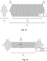
- Fig. 3a shows example waveforms of the first and second wavelets W 1 , W 2 .
- the first wavelet W 1 has an initial or leading portion ⁇ i in which the amplitude of the wavelet increases from zero, an end or trailing portion ⁇ e in which the amplitude returns to zero, and a middle or intermediate portion ⁇ m , between the leading and trailing portions.
- the intermediate portion ⁇ m refers to a portion of the first wavelet W 1 in which at least the center frequency is substantially constant, and typically also the amplitude.
- the initial portion ⁇ i refers to the leading transient portion of the first wavelet W 1 in which its amplitude ramps up from zero.
- the end portion ⁇ i refers to the trailing transient portion of the first wavelet W 1 in which its amplitude reduces to zero.
- the term "amplitude of a wavelet” here refers to the amplitude of the modulation of the carrier (i.e. the amplitude of the envelope of the wavelet) rather than the oscillatory instantaneous amplitude of the carrier.
- the center frequency may during the initial and/or end portions ⁇ i , ⁇ e be unstable, e.g. due to characteristics of the first wavelet generator 6. Therefore, as previously discussed, the samples of the convolution which may form the basis for a reliable and accurate center frequency estimate are those which are obtained by mixing the second wavelet W 2 with the middle / constant frequency portion ⁇ m of the first wavelet W 1 . Accordingly, the duration ⁇ 2 of the second wavelet W 2 is smaller than the duration ⁇ m of the middle / constant frequency portion ⁇ m of the first wavelet W 1 .
- the samples x j are thus obtained when the timing offset ⁇ j between the first and second wavelets W 1 , W 2 is such that the second wavelet W 2 overlaps the constant frequency portion ⁇ m of the first wavelet W 1 , but neither the initial portion ⁇ i nor the end portion ⁇ e .
- Fig. 3b showing the waveform of the (full) convolution of the wavelets W 1 , W 2 shown in Fig. 3a , the samples x j are thus obtained from the "Constant" portion ⁇ 3 of the convolution.
- the number of samples obtained from the constant frequency portion ⁇ 3 typically depends on factors such as desired measurement accuracy, amount of processing resources available for storing and processing the samples, and the time available for performing the measurements.
- the sequence of samples x j 1... M spans at least one period of the constant frequency portion ⁇ 3 of the convolution. A greater span may both facilitate determining the time rate of change of the un-wrapped phase values (see below) and allow for averaging of the frequency estimate across a plurality of periods.
- the time steps ⁇ j ) between the samples of the respective sub-sequences is smaller than a spacing between the sub-sequences.
- the sequence of samples may span at least one period (advantageously at least two) of the constant frequency portion ⁇ 3 of the convolution and be acquired with a sample rate sufficient to avoid aliasing.
- An instantaneous phase value may be estimated for each IQ-pairs (e.g. as the argument of the IQ-pair, arg ( I , Q )). Any conventional IQ demodulation technique may be used.
- the DSP 18 may store the frequency estimates in a memory of, or connected to, the DSP 18 for retrieval and/or further processing, and/or output to peripheral circuitry via a communication bus of the electronic device 1. As an example, the DSP 18 may compare the frequency f 1 of the first wavelet W 1 to a reference frequency or reference frequency band to determine whether the frequency f 1 of the first wavelet W 1 is within a tolerance.
- the resonance frequency may be tuned responsive to the estimated center frequency deviating from the reference frequency or reference frequency band such that the center frequency f 1 is tuned within a tolerance of the reference frequency or band. This may be performed as an iterative process (e.g. iteratively: estimating f 1 , comparing f 1 to the reference frequency or band, and tuning the resonance frequency) wherein the center frequency f 1 may be tuned to iteratively approach the reference frequency or band (e.g. approach the center frequency of the reference band).
- a tunable resonance frequency e.g. the carrier of the first wavelet W1 may be generated by a voltage-controlled oscillator
- the intermediate portion ⁇ m of the first wavelet W 1 presents a substantially constant frequency.
- the term "substantially constant” may here be understood in light of the fact that even an oscillatory signal with a limited temporal extent will have a certain non-zero width in the frequency domain.
- the center frequency f 1 may only be determined within a certain precision which in the end is limited among others by the duration ⁇ m . Accordingly, the peak in the spectrum of the first wavelet W 1 which corresponds to the center frequency may have a non-zero bandwidth.
- the center frequency may vary by at most 5%, or at most 2% or at most 1% during the intermediate portion ⁇ m .
- the center frequency f 1 may for example lie within a band of width 1 GHz or less, such as 0.5 GHz or 0.1 GHz.
- the intermediate portion ⁇ m of the first wavelet W 1 may also present a substantially constant amplitude. This may improve the precision of the frequency estimation since an amplitude modulation within the intermediate portion ⁇ m of the first wavelet W 1 will manifest itself as a (further) broadening of the peak corresponding to the center frequency f 1 .
- an amplitude variation of at most 5%, or at most 2% or at most 1% may be considered as substantially constant within the measurement tolerances of the present frequency estimation method. That said, even greater amplitude variations may be tolerable in some instances, e.g. if there are greater error sources within the measurement which anyway mask the broadening due to the amplitude modulation.
- there is in no requirement on a substantially constant center frequency or amplitude for the second wavelet W 2 Accordingly, various designs of the second wavelet W 2 are compatible with the frequency estimation method.
- the frequency spectrum of the second wavelet W 2 comprises a lobe or peak overlapping (i.e. comprising) the center frequency f 1 of the first wavelet W 1 which is to be estimated.
- the lobe or peak may advantageously be a main lobe or main peak of the frequency spectrum of the second wavelet W 2 as this allows the portion of the spectrum of the second wavelet W 2 comprising the greatest energy to be mixed into the samples x j .
- side lobes or secondary peaks may be used provided they include a substantial energy.
- Fig. 5 schematically shows a further example corresponding to the example of Fig. 4 but for a second wavelet W 2 with a square modulation and a frequency chirp (i.e. frequency sweep).
- the frequency chirp produces a distinct and broad main lobe in the frequency spectrum of the second wavelet W 2 , overlapping the carrier of the first wavelet W 1 on either sides.
- This produces a peak (P) in the frequency spectrum of the convolution at the carrier frequency of the first wavelet W 1 , allowing the center/carrier frequency of the first wavelet W 1 to be estimated.
- the frequency spectrum of the second wavelet W 2 comprises a band (i.e. a continuous frequency range) with non-zero energy overlapping the center frequency of the first wavelet W 1 .
- Fig. 4 shows an idealized triangular envelope of the second wavelet W 2
- less ideal triangular amplitude modulations may produce equally useable results.
- the rise and fall times of the edges of the envelope may be different, and/or need not increase/decrease strictly linearly.
- a second wavelet W 2 with a substantially trapezoidal envelope may be used.
- a frequency chirp also with non-square envelopes may be used, such as substantially triangular or trapezoidal. It is also possible to use frequency chirps with either increasing or decreasing frequency.
- control signals needed to cause the electronic device 1 to perform the method described above, as well as the various control signals needed for controlling the timing circuit 4, the wavelet generators 6, 8, the ADC 16 and the DSP 18, etc. may be provided by a controller 20 of the electronic device 1.
- the controller 20 may e.g. be implemented in dedicated circuitry, an ASIC or an FPGA.
- a main controller may alternatively be implemented by a dedicated microcontroller, or by a microprocessor in combination with a computer readable medium, such as a non-volatile memory, storing instructions for causing the microprocessor to provide the control signals etc. to the electronic device 1.
- the frequency estimation method set out above may be used in various applications, including various types of electronic devices.
- the electronic device 1 may for instance be configured as a radar device, such as an UWB mmWave radar device.
- the first wavelet generator 6 may for instance form part of a transmitter of the radar device 1.
- the radar device 1 may transmit wavelets generated by the first wavelet generator 6.
- the wavelets may be transmitted towards a radar target via an antenna 2 of the radar device 1 (e.g. a directional antenna such as a dipole antenna, a Yagi antenna or a phased array antenna).
- Radar returns reflected by a radar target may be received and processed by a receiver of the radar device 1 using techniques which per se are known in the art. For instance, radar returns comprising reflected wavelets may be received (e.g. via the antenna 2 or via a separate antenna of the receive part) and sampled.
- the radar samples may be processed to measure parameters such as time-of-flight, amplitude and/or phase.
- the radar returns may be sampled using any suitable existing techniques, such as time-diluted sampling of a sequence of radar returns from a sequence of coherently generated wavelets, or direct / real-time sampling of each radar return (provided the sampling circuit of the receiver has a sufficient bandwidth).
- the radar target may be a hand or a finger of a user locate in relative proximity to an electronic device (e.g. a tablet computer, a laptop computer, a media player, a smart watch, headphones or some other electronic device implementing a radar-based contactless user interaction).
- an electronic device e.g. a tablet computer, a laptop computer, a media player, a smart watch, headphones or some other electronic device implementing a radar-based contactless user interaction.
- the radar target may be a structure such as a wall or some obstacle whose presence and/or position may be relevant for a movement decision by the autonomous robot.
- a surface scanning application the radar target may be a surface of interest (e.g. a surface traversed by a robot).
- the first wavelet generator 6 may also or alternatively form part of a receiver of the radar device 1, wherein the first wavelet generator 6 may generate reference or template wavelets for use in time-diluted sampling of radar returns.
Landscapes
- Engineering & Computer Science (AREA)
- Radar, Positioning & Navigation (AREA)
- Remote Sensing (AREA)
- Computer Networks & Wireless Communication (AREA)
- Physics & Mathematics (AREA)
- General Physics & Mathematics (AREA)
- Measuring Frequencies, Analyzing Spectra (AREA)
Priority Applications (2)
| Application Number | Priority Date | Filing Date | Title |
|---|---|---|---|
| EP23199885.7A EP4530661A1 (de) | 2023-09-26 | 2023-09-26 | Verfahren zur schätzung der mittenfrequenz eines wavelets |
| US18/895,682 US20250102620A1 (en) | 2023-09-26 | 2024-09-25 | Method for estimating a center frequency of a wavelet |
Applications Claiming Priority (1)
| Application Number | Priority Date | Filing Date | Title |
|---|---|---|---|
| EP23199885.7A EP4530661A1 (de) | 2023-09-26 | 2023-09-26 | Verfahren zur schätzung der mittenfrequenz eines wavelets |
Publications (1)
| Publication Number | Publication Date |
|---|---|
| EP4530661A1 true EP4530661A1 (de) | 2025-04-02 |
Family
ID=88204449
Family Applications (1)
| Application Number | Title | Priority Date | Filing Date |
|---|---|---|---|
| EP23199885.7A Pending EP4530661A1 (de) | 2023-09-26 | 2023-09-26 | Verfahren zur schätzung der mittenfrequenz eines wavelets |
Country Status (2)
| Country | Link |
|---|---|
| US (1) | US20250102620A1 (de) |
| EP (1) | EP4530661A1 (de) |
Citations (4)
| Publication number | Priority date | Publication date | Assignee | Title |
|---|---|---|---|---|
| WO2008066537A1 (en) * | 2006-12-01 | 2008-06-05 | Aai Corporation | Method for aligning rf pulse timing |
| CN105022036A (zh) * | 2015-08-26 | 2015-11-04 | 成都信息工程大学 | 风廓线雷达风速测定方法 |
| CN106526566A (zh) * | 2016-12-07 | 2017-03-22 | 中国船舶重工集团公司第七二四研究所 | 基于fpga高速预处理的信号脉内特征实时分析处理方法 |
| EP4187280A1 (de) * | 2021-11-26 | 2023-05-31 | Acconeer AB | Verfahren zur durchführung von radarmessungen und radarvorrichtung |
-
2023
- 2023-09-26 EP EP23199885.7A patent/EP4530661A1/de active Pending
-
2024
- 2024-09-25 US US18/895,682 patent/US20250102620A1/en active Pending
Patent Citations (4)
| Publication number | Priority date | Publication date | Assignee | Title |
|---|---|---|---|---|
| WO2008066537A1 (en) * | 2006-12-01 | 2008-06-05 | Aai Corporation | Method for aligning rf pulse timing |
| CN105022036A (zh) * | 2015-08-26 | 2015-11-04 | 成都信息工程大学 | 风廓线雷达风速测定方法 |
| CN106526566A (zh) * | 2016-12-07 | 2017-03-22 | 中国船舶重工集团公司第七二四研究所 | 基于fpga高速预处理的信号脉内特征实时分析处理方法 |
| EP4187280A1 (de) * | 2021-11-26 | 2023-05-31 | Acconeer AB | Verfahren zur durchführung von radarmessungen und radarvorrichtung |
Non-Patent Citations (1)
| Title |
|---|
| SHAMIK SARKAR ET AL: "RadYOLOLet: Radar Detection and Parameter Estimation Using YOLO and WaveLet", ARXIV.ORG, CORNELL UNIVERSITY LIBRARY, 201 OLIN LIBRARY CORNELL UNIVERSITY ITHACA, NY 14853, 21 September 2023 (2023-09-21), XP091619835 * |
Also Published As
| Publication number | Publication date |
|---|---|
| US20250102620A1 (en) | 2025-03-27 |
Similar Documents
| Publication | Publication Date | Title |
|---|---|---|
| US6646587B2 (en) | Doppler radar apparatus | |
| KR102331790B1 (ko) | 송신기-수신기 시스템 | |
| EP4187280B1 (de) | Verfahren zur durchführung von radarmessungen und radarvorrichtung | |
| CN105793677B (zh) | 具有多个波形的自适应雷达系统 | |
| CN105319544B (zh) | 用于使用可调整自干扰抵消来校准和优化调频连续波雷达高度仪的系统和方法 | |
| US8559554B2 (en) | Radio transmitter, radio receiver, system and method with a radio transmitter and radio receiver | |
| US8854254B2 (en) | Ultra-wideband short-pulse radar with range accuracy for short range detection | |
| US8471761B1 (en) | Wideband radar nulling system | |
| US20070259636A1 (en) | RF bridge for an angle rate interferometer | |
| US20060061505A1 (en) | High range resolution radar system | |
| Wang et al. | Nonlinearity correction for range estimation in FMCW millimeter-wave automotive radar | |
| EP4530661A1 (de) | Verfahren zur schätzung der mittenfrequenz eines wavelets | |
| US20260086197A1 (en) | A radar device and a method for calibrating the radar device | |
| US11009597B2 (en) | Phase noise compensation in digital beamforming radar systems | |
| GB2545041A (en) | Receiver with automatic gain control by an alternating current closed loop for radar applications | |
| EP1522872A1 (de) | Impulsradargerät | |
| US20220268914A1 (en) | Automatic image rejection calibration for radar systems using quadrature transceivers | |
| Kim et al. | A wall-clutter rejection technique using two PLLs and a phase controller for wall-penetrating FMCW radar | |
| CN207780234U (zh) | 宽带自适应频率跟踪系统 | |
| Carlowitz et al. | A low power Pulse Frequency Modulated UWB radar transmitter concept based on switched injection locked harmonic sampling | |
| KR101766765B1 (ko) | 선형 위상 변위 방식의 반사계 시스템 | |
| Zilevu et al. | Waveforms and signal processing for high-accuracy microwave metrology | |
| Wan et al. | Ultra-wideband radar signals generated technology with two-channel | |
| Sorochan et al. | Radio altimeter with J-correlation signal processing | |
| RU2343499C1 (ru) | Нелинейный радар для дистанционного мониторинга продуктопроводов |
Legal Events
| Date | Code | Title | Description |
|---|---|---|---|
| PUAI | Public reference made under article 153(3) epc to a published international application that has entered the european phase |
Free format text: ORIGINAL CODE: 0009012 |
|
| STAA | Information on the status of an ep patent application or granted ep patent |
Free format text: STATUS: THE APPLICATION HAS BEEN PUBLISHED |
|
| AK | Designated contracting states |
Kind code of ref document: A1 Designated state(s): AL AT BE BG CH CY CZ DE DK EE ES FI FR GB GR HR HU IE IS IT LI LT LU LV MC ME MK MT NL NO PL PT RO RS SE SI SK SM TR |
|
| STAA | Information on the status of an ep patent application or granted ep patent |
Free format text: STATUS: REQUEST FOR EXAMINATION WAS MADE |
|
| 17P | Request for examination filed |
Effective date: 20250806 |