EP4530657A2 - Détermination de localisation de dispositif sans fil multiple - Google Patents
Détermination de localisation de dispositif sans fil multiple Download PDFInfo
- Publication number
- EP4530657A2 EP4530657A2 EP25154121.5A EP25154121A EP4530657A2 EP 4530657 A2 EP4530657 A2 EP 4530657A2 EP 25154121 A EP25154121 A EP 25154121A EP 4530657 A2 EP4530657 A2 EP 4530657A2
- Authority
- EP
- European Patent Office
- Prior art keywords
- wireless device
- location
- phase differences
- orientation
- wireless
- Prior art date
- Legal status (The legal status is an assumption and is not a legal conclusion. Google has not performed a legal analysis and makes no representation as to the accuracy of the status listed.)
- Withdrawn
Links
Images













Classifications
-
- H—ELECTRICITY
- H04—ELECTRIC COMMUNICATION TECHNIQUE
- H04W—WIRELESS COMMUNICATION NETWORKS
- H04W4/00—Services specially adapted for wireless communication networks; Facilities therefor
- H04W4/02—Services making use of location information
- H04W4/025—Services making use of location information using location based information parameters
- H04W4/026—Services making use of location information using location based information parameters using orientation information, e.g. compass
-
- G—PHYSICS
- G01—MEASURING; TESTING
- G01S—RADIO DIRECTION-FINDING; RADIO NAVIGATION; DETERMINING DISTANCE OR VELOCITY BY USE OF RADIO WAVES; LOCATING OR PRESENCE-DETECTING BY USE OF THE REFLECTION OR RERADIATION OF RADIO WAVES; ANALOGOUS ARRANGEMENTS USING OTHER WAVES
- G01S3/00—Direction-finders for determining the direction from which infrasonic, sonic, ultrasonic or electromagnetic waves, or particle emission, not having a directional significance, are being received
- G01S3/02—Direction-finders for determining the direction from which infrasonic, sonic, ultrasonic or electromagnetic waves, or particle emission, not having a directional significance, are being received using radio waves
- G01S3/14—Systems for determining direction or deviation from predetermined direction
- G01S3/46—Systems for determining direction or deviation from predetermined direction using antennas spaced apart and measuring phase or time difference between signals therefrom, i.e. path-difference systems
- G01S3/48—Systems for determining direction or deviation from predetermined direction using antennas spaced apart and measuring phase or time difference between signals therefrom, i.e. path-difference systems the waves arriving at the antennas being continuous or intermittent and the phase difference of signals derived therefrom being measured
-
- G—PHYSICS
- G01—MEASURING; TESTING
- G01S—RADIO DIRECTION-FINDING; RADIO NAVIGATION; DETERMINING DISTANCE OR VELOCITY BY USE OF RADIO WAVES; LOCATING OR PRESENCE-DETECTING BY USE OF THE REFLECTION OR RERADIATION OF RADIO WAVES; ANALOGOUS ARRANGEMENTS USING OTHER WAVES
- G01S5/00—Position-fixing by co-ordinating two or more direction or position line determinations; Position-fixing by co-ordinating two or more distance determinations
- G01S5/02—Position-fixing by co-ordinating two or more direction or position line determinations; Position-fixing by co-ordinating two or more distance determinations using radio waves
- G01S5/06—Position of source determined by co-ordinating a plurality of position lines defined by path-difference measurements
-
- H—ELECTRICITY
- H04—ELECTRIC COMMUNICATION TECHNIQUE
- H04W—WIRELESS COMMUNICATION NETWORKS
- H04W16/00—Network planning, e.g. coverage or traffic planning tools; Network deployment, e.g. resource partitioning or cells structures
- H04W16/18—Network planning tools
-
- H—ELECTRICITY
- H04—ELECTRIC COMMUNICATION TECHNIQUE
- H04W—WIRELESS COMMUNICATION NETWORKS
- H04W4/00—Services specially adapted for wireless communication networks; Facilities therefor
- H04W4/02—Services making use of location information
- H04W4/029—Location-based management or tracking services
-
- H—ELECTRICITY
- H04—ELECTRIC COMMUNICATION TECHNIQUE
- H04W—WIRELESS COMMUNICATION NETWORKS
- H04W64/00—Locating users or terminals or network equipment for network management purposes, e.g. mobility management
- H04W64/003—Locating users or terminals or network equipment for network management purposes, e.g. mobility management locating network equipment
-
- H—ELECTRICITY
- H04—ELECTRIC COMMUNICATION TECHNIQUE
- H04W—WIRELESS COMMUNICATION NETWORKS
- H04W88/00—Devices specially adapted for wireless communication networks, e.g. terminals, base stations or access point devices
- H04W88/08—Access point devices
Definitions
- the present application relates to wireless communications and, more particularly, to methods and/or apparatus for deployment of wireless access points (APs) that are utilized for determining location of objects associated with wireless networks.
- APs wireless access points
- Estimation of location of a wireless transmitter is utilized to provide many functions.
- location-based services include navigation, location specific content delivery, and many other applications.
- This disclosure describes example embodiments that determine a location of a first wireless device based on phase differences of waveforms exchanged between the first wireless device and a second wireless device.
- a location of a device transmitting the waveforms is determined based on the phase differences.
- a location of the device receiving the waveforms is determined based on the phase differences.
- phase differences observed from signals transmitted by a device and signals received by the device are used in determining a location of the device.
- At least one of the first wireless device and second wireless device include a plurality or receive elements.
- the disclosed embodiments do not require a stable reference signal which may be difficult to maintain in different environments. Instead, the disclosed embodiments utilize the plurality of receive elements (e.g. antennas) distributed in a two or three dimensional orientations.
- Some of the disclosed embodiments define a plurality of geographic regions in proximity to a wireless device, and then identify expected phase differences (phase difference signatures (PDSs)) for each of the plurality of geographic regions.
- PDSs phase difference signatures
- a location of a device receiving signals and determining phase differences is at an unknown location.
- a location of a device transmitting signals is unknown. For each of these scenarios, expected phase differences of a signal received from a transmitter located in the plurality of geographic regions are determined.
- the exchange of signals described above can be used to not only determine a device's location, but also its orientation. While, as discussed above, phase differences of received signals can be used to estimate a location of a wireless transmitter, these received signals can also be used to determine a location of a specific transmit element (e.g. antenna).
- a specific transmit element e.g. antenna
- two wireless devices exchange signals, with phase differences of the exchanged signals determining distances between transmit/receive element pairs of the two devices. Thus, for example, if each device includes four antennas, there are six pairs of transmit/receive elements between the two devices. Location of each transmit element of a first wireless device can be determined based on at least phase difference information collected from four receive elements of the second device.
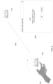
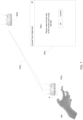
- FIG. 5 shows a first wireless device alignment procedure.
- FIG. 5 shows two wireless devices, a first wireless device 552a and a second wireless device 552b.
- the wireless devices 552a-b are analogous to or equivalent to any of the APs discussed above.
- FIG. 5 shows signals 554a being exchanged between the first wireless device 552a and the second wireless device 552b. Based on the exchanged signals, at least some of the disclosed embodiments determine an orientation of the first wireless device 552a relative to the second wireless device 552b. Details of this orientation determination are explained further below.
- Some embodiments of this disclosure generate instructions to align an orientation of the first wireless device 552a with an orientation of the second wireless device 552b. To demonstrate, FIG.
- FIG. 7 shows a third wireless device alignment procedure.
- FIG. 7 also shows the first wireless device 552a and the second wireless device 552b.
- Signals 554c are exchanged between the first wireless device 552a and the second wireless device 552b in order to determine an orientation of the first wireless device 552a relative to an orientation of the second wireless device 552b.
- An alignment dialog 556c displays instructions 558c that request a user to adjust the first wireless device 552a with respect to a second dimension, different than the first dimension adjusted with respect to FIGs. 5-6 .
- the instructions 558c requests adjustment of the first wireless device such that a left side of the first wireless device 552a is higher relative to a right side of the first wireless device 552a.
- Some of the disclosed wireless devices provides adjustable legs (e.g. leg 562) to facilitate alignment of the wireless device about each of a yaw (Y), pitch (X), and roll (Z) axes.
- FIG. 7 demonstrates that the contemplated alignment process can generate instructions to align a wireless device, and validate those alignments, in at least three dimensions.
- FIGs. 5-7 describe a manual alignment procedure of a wireless device, with the manual alignment driven by instructions generated by the disclosed embodiments
- other embodiments provide for alignment of a wireless device's orientation without manual intervention.
- some embodiments of a wireless device are configured with electric motors capable of changing an orientation of a wireless device about each of a X, Y, and Z axis.
- the differences in orientation between two devices is provided to an orientation controller included in one of the devices.
- the orientation controller is configured to adjust the orientation of the electric motors as necessary to place the first wireless device in an orientation consistent with the orientation of the second wireless device.
- the first and/or second wireless devices are configured to be ceiling mountable.
- the orientation controller is configured to control an orientation of the first wireless device with respect to the orientation of the second wireless device and the ceiling such that the first and second wireless devices orientations are aligned.
- FIG. 8 is a block diagram of an example access point 800 (e.g., any one or more of access points AP 142a-d) in accordance with one or more of the disclosed embodiments.
- Access point 800 includes wired interface 830, wireless interfaces 836, 842, a hardware processor 806, e.g., a CPU, one or more hardware memories 812, and an assembly of components 808, e.g., assembly of hardware components, e.g., assembly of circuits, coupled together via a bus 809 over which the various elements may interchange data and information.
- Wired interface 830 includes a receiver 832 and a transmitter 834.
- the wired interface 830 couples the access point 800 to a network 134 (e.g. the Internet) of FIG. 1 .
- a network 134 e.g. the Internet
- First wireless interface 836 (e .g., a Wi-Fi interface, or an 802.11 interface), includes receiver 838 coupled to receive antenna 839, via which the access point may receive wireless signals from communications devices, e.g., wireless terminals, and transmitter 840 coupled to a transmit antenna 841.
- the access point transmits, via the transmit antenna 841, wireless signals to communications devices, e.g., wireless terminals.
- Second wireless interface 842 e .g., a Bluetooth interface, includes receiver 844 coupled to an antenna 845, via which the access point may receive wireless signals from communications devices, e.g., wireless terminals, and transmitter 846 coupled to a transmit antenna 847 via which the access point may transmit wireless signals to communications devices, e.g., wireless terminals.
- FIG. 9 provides greater details of this phase processing.
- Wireless interfaces e.g., 836 and or 842 may, and usually do, include phase difference determination component as explained in greater details with reference to FIG. 9 below.
- the one or more hardware memories 812 include routines 814 and data/information 816.
- Routines 814 include assembly of components 818, e.g., an assembly of software components, and Application Programming Interface (API) 820.
- Data/information 816 includes configuration information 822, device status log including error events and normal events captured as messages in a system log or an error log 824 and a dynamic list of measured arrival phase values 826 which identifies the relative arrival phase at different antennas of one AP of signals transmitted from a second AP.
- the memory stores the phase difference between signals arriving at any antenna pairs (not shown).
- FIG. 9 is a view 900 showing an example of a wireless interface 950, such as any one or more of the interfaces 836 or 842 of FIG. 8 .
- a wireless interface 950 such as any one or more of the interfaces 836 or 842 of FIG. 8 .
- this illustrative example shows an interface with four receivers 954a, 954b, 954c, and 954d connected to four receiver antennas 955a, 955b, 955c, and 955d accordingly.
- four transmitters 956a, 956b, 956c, and 956d are connected to four transmitter antennas 957a, 957b, 957c, and 957d.
- a waveform as received by antenna 955a and receiver 954a serves as a reference.
- Various embodiments can choose any antenna of a receiving device as a reference.
- the reference is fed into phase differentiators 960, 962 and 964.
- the other inputs of the phase differentiators are connected to the outputs of receivers 954b, 954c, and 954d respectfully.
- the phase differentiators detect the difference between the phases of the reference signal and the waveforms received via antennas 955b, 955c, and 955d and their corresponding receivers 954b, 954c, and 954d.
- n independent phase differences are generated.
- CPDV 360 ⁇ p 1 , 360 ⁇ p 2 , 360 ⁇ p 3 , ... . ... , 360 ⁇ p n
- Equation 3 and Equation 4 demonstrate generation of a phase difference for a waveform of a single frequency
- some embodiments include phase differences expected from signals of different frequencies.
- a first set of pi where i ⁇ n define expected phase differences of waveforms at a first frequency
- a second set of p i where n ⁇ i ⁇ m define expected phase differences of waveforms at a second frequency. This can be repeated for more than two frequencies, as this simply operates as an example.
- expected phase differences generated by various embodiments include those expected phase differences generated according to Equation 2 and/or Equation 3.
- the location of the wireless transmitter is determined by comparing the components of expected phase differences with the measured phase difference. If the expected phase differences include both a phase difference and its complement, then the wireless receiver needs only to produce the measured phase difference (and does not need to produce the complement of the measured difference). However, if the signature does not include the complementary phase differences, then the differentiators need to produce both the measured phase differences and their complements.
- FIG. 10 shows an example top physical view 1000 of an example AP 1050.
- the example AP 1050 includes a plurality of antennas, labeled as antenna 1060a, antenna 1060b, antenna 1065a, antenna 1065b, and antennas 1070a-f.
- antenna 1060a and antenna 1060b are used to monitor and control the radio e.g., Wi-Fi, network.
- antennas 1065a and 1065b are used for communication in the 5.4 GHz band between the AP and user equipment UE, such as WT.
- antennas 1070a-f are used for communication in the either the 2.4 GHz or the 5.4 GHz bands between the AP and user equipment UE, such as WT.
- Some embodiments use these antennas to determine the distances between any transmitting antenna on a first AP and a receiving antenna on a second AP as well as the distances between any transmitting antenna on a second AP and a receiving antenna on a first AP.
- the distances are determined based on the difference in arrival phase values of signals in one or multiple antenna pairs communicated over one or more frequency bands.
- a detailed explanation of how the distances between the various pairs of transmitter/receiver antennas are calculated is provided in the Phase Differences Application.
- Any one of the antennas is used for transmitting and receiving signals that facilitate estimation of a position and orientation of one AP with respect to another.
- FIG. 11 is a block diagram of an example of a location determination and SPM apparatus 1100.
- the location determination and SPM apparatus 1100 is a network node, e.g., a location and orientation server such as automated device locations determination server.
- the location determination and SPM apparatus 1100 of FIG. 11 is the location and orientation server 165 of FIG. 1
- the location determination and SPM apparatus 1100 is located in the cloud or is part of an access point such as any one of the access points or devices shown in FIG. 1 .
- Location determination and SPM apparatus 1100 includes a communications interface 1130, a hardware processor 1106, an output device 1108, e.g., display, printer, etc., an input device 1110, e.g., keyboard, keypad, touch screen, mouse, etc., one or more hardware memories 1112 and an assembly of components 1140, e.g., assembly of hardware components, e.g., assembly of circuits, coupled together via a bus 1109 over which the various elements may interchange data and information.
- the communications interface 1130 includes an Ethernet interface in some embodiments. Communications interface 1130 couples the location determination and SPM apparatus 1100 to a network and/or the Internet.
- Communications interface 1130 includes a receiver 1132 via which the location and orientation server apparatus can receive signals from wireless transmitters, and a transmitter 1134, via which the location determination and SPM apparatus 1100 can send data and information, e.g., information regarding location of various wireless transmitter to the transmitters themselves, to any other network attached server such as the network management server, etc.
- the one or more hardware memories 1112 includes routines 1114 and location signature data/information 1120.
- Routines 1114 include assembly of components 1118, e.g., an assembly of software components, and Application Programming Interface (API) 1117.
- routines 1114 define software that implement methods for generating instructions to guide positioning and orienting of an AP to a defined position and orientation that is aligned with a position and orientation of a reference AP.
- the routines determine the location and orientation of each AP in reference to the reference AP and use this information to determine the location of other mobile devices such as UEs shown n FIG. 1 or other WT.
- Location signature data/information 1120 includes, region coordinates 1124.
- the coordinates can have a single dimension (for locating a wireless transmitter along a specific straight path), two dimensions (for locating a device in a two dimensional plan such as on a floor of an enterprise), or three dimensions (for locating a wireless device within a three dimensional volume such as a device on a specific shelf in a storage room).
- location signature data/information 1120 also includes columns 1125, 1126, 1127, 1128, and 1129, each column indicative of a relative phase of a waveform expected to be received from a specific region by a specific receive element e.g., A1, A2, A2', A3, and A3'.
- receive element A1 is selected to be the reference receive element and is assigned a phase difference of 0 (with respect to itself). The phases of the signals received by the other receive elements are measured with reference to the waveform (e.g. reference phase) received by receive element A1.
- antenna element A2 can be selected to be another reference antenna resulting in additional phase differences between signals received by antennas A2-A3, A2-A4, etc. Consequently, the number of columns in the location signature data/information would increase or decrease accordingly.
- Columns 1126 and 1128 provide the phase difference assuming that the waveform from a wireless transmitter located in a specific region arrived first at the reference receive element and then at the corresponding i th receive element.
- Columns 1127 and 1129 provide the 360 degrees complementary phase difference assuming that the waveform from a wireless transmitter located in a specific region arrived first at the corresponding i th receive element and then at the reference receive element.
- the wireless interface 950 of FIG. 9 generates 360 degrees complement phase difference when the location signature does not include a column with the 360 degrees complement phase difference signature.
- the one or more hardware memories 1112 also include configuration information 1122 which includes operational parameters that are either programmed into the system or entered by the system administrator.
- the one or more hardware memories 1112 also include example phase delta tables 1150, 1155, and 1160 containing phase difference information.
- the tables include a 360 degree complementary phase difference information.
- the information in the tables is refreshed periodically, (e.g., once every second), to reflect an updated position of the wireless device, e.g., transmitter.
- Phase delta tables 1150, 1155, and 1160 include the IDs 1151, 1156, through 1161 of the wireless transmitters from which a received waveform was transmitted and for which phase deltas were measured.
- the tables also include phase deltas information 1152, 1157, through 1162 measured between signals arriving at any antenna pair and.
- phase delta measurement error which may vary by embodiment.
- the phase delta measurement error is configurable, or is dynamically determined.
- An example phase delta measurement error is ⁇ ten (10) degrees.
- the measurement error can be either fixed (e.g. hard coded) or configured via a user interface as one of the configuration information 1122.
- the measured phase difference information is compared against the expected phase difference information (or its 360 complement) for a particular region (the expected phase difference of each region).
- the measured phase differences are considered to match the expected phase differences if they fall within a predefined error tolerance level. If the phase differences match those expected in a region, some embodiments determine that the wireless antenna is possibly located in that region.
- Some embodiments determine whether a measured set of phase differences "matches" an expected set of phase differences for a particular region based on Equation 6 below: abs si ⁇ pi ⁇ threshold where:
- FIG. 12 is a block diagram of an example of a network node 1200.
- the network node 1200 is a device or a server attached to the network 134.
- network node 1200 of FIG. 12 represents any one or more of server 110, 116, 122, 128, 136 of FIG. 1 , and/or any one or more of the routers 185, and/or the switches 180 of FIG. 1 .
- Network node 1200 includes a communications interface 1202, (e.g., an Ethernet interface), a hardware processor 1206, an output device 1208, (e.g., display, printer, etc.), an input device 1210, (e.g., keyboard, keypad, touch screen, mouse), one or more hardware memories 1212, and an assembly of components 1216 (e.g., one or more of an assembly of hardware modules, assembly of circuits), coupled together via a bus 1209 over which the various elements may interchange data and information.
- Communications interface 1202 couples the network node 1200 to a network and/or the Internet. Though only one interface is shown, those skilled in the art should recognize that routers and switches may, and usually do, have multiple communication interfaces.
- Communications interface 1202 includes a receiver 1220 via which the network node 1200, e.g. a server, can receive data and information, e.g., including operation related information, e.g., registration request, AAA services, DHCP requests, Simple Notification Service (SNS) look-ups, and Web page requests, and a transmitter 1222, via which the network node 1200, e.g., a server, can send data and information, e.g., including configuration information, authentication information, web page data, etc.
- data and information e.g., including operation related information, e.g., registration request, AAA services, DHCP requests, Simple Notification Service (SNS) look-ups, and Web page requests
- SNS Simple Notification Service
- Memory 1212 includes routines 1214 and data information 1230.
- Routines 1214 include an assembly of components 1232, e.g., an assembly of software components.
- the data information 1230 includes a system log and/or an error log.
- FIG. 13 is a block diagram of an example communications device.
- the communications device 1300 is user equipment (UE), such as any of the devices UE 1 138, ..., UE Z 140, UE 1' 146, ..., UE Z' 148 discussed in greater above.
- Communications device 1300 includes wired interfaces 1302, wireless interfaces 1304, a hardware processor 1306, (e.g., a CPU), an electronic display 1308, an input device 1310, one or more hardware memories 1312, and an assembly of components 1316, e.g., assembly of hardware module, e.g., assembly of circuits, coupled together via a bus 1309 over which the various elements may interchange data and information.
- Wired interface 1302 includes a receiver 1320 and a transmitter 1322.
- the wired interface 1302 couples the communications device 1300, e.g. a UE, to a network 134 (e.g. the Internet) of FIG. 1 .
- the wireless interface 1304 includes cellular interface 1324, first wireless interface 1326, (e.g., 802.11 Wi-Fi interface), and a second wireless interface 1328 (e.g., a Bluetooth interface).
- the cellular interface 1324 includes a receiver 1332 coupled to a receiver antenna 1333 via which the communications device 1300, e.g. UE, may receive wireless signals from a wireless device, such as any of the access points 142a-d , and transmitter 1334 coupled to a transmit antenna 1335 via which the communications device 1300, e.g. UE, may transmit wireless signals to a wireless device, such as any of the APs 142a-d.
- First wireless interface 1326 e.g., a Wi-Fi interface, e.g.
- 802.11 interface includes receiver 1336 coupled to receive antenna 1337, via which the communications device 1300, e.g., UE, may receive wireless signals from communications devices, e.g., APs, and transmitter 1338 coupled to a transmit antenna 1339 via which the communications device 1300, e.g., UE, may transmit wireless signals to communications devices, e.g., APs.
- the second wireless interface 1328 e.g., a Bluetooth interface, includes receiver 1340 coupled to receive antenna 1341, via which the communications device 1300, e.g.
- a UE may receive wireless signals from communications devices, e.g., APs, and transmitter 1342 coupled to a transmit antenna 1343 via which the communications device 1300, e.g., a UE, may transmit wireless signals to communications devices, e.g., APs.
- communications devices e.g., APs
- transmitter 1342 coupled to a transmit antenna 1343 via which the communications device 1300, e.g., a UE, may transmit wireless signals to communications devices, e.g., APs.
- Memory 1312 includes routines 1314 and data/information 1317.
- Routines 1314 include assembly of components 1315, e.g., an assembly of software components.
- Data/information 1317 may include configuration information as well as any additional information required for normal operations of communications device 1300. Data information includes also system log or error log..
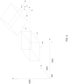
- FIG. 14 shows an example misalignment 1400 between orientations of two wireless devices.
- the two wireless devices include a first wireless device 1405 and a second wireless device 1445.
- each of the two wireless devices are access points.
- a position and orientation of the wireless device 1405 is known.
- the position and orientation of the wireless device AP 1405 is known or is aligned with respect to a first coordinate system, represented by X axis 1402 and Y axis 1404.
- the first wireless device 1405 is aligned with the first coordinate system in that predefined fixed locations or features of the first wireless device 1405 (e.g.one or more of corners of the second wireless device 1445, one or more antenna locations of the second wireless device 1445, etc.) have particular coordinates within the first coordinate system.
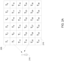
- the wireless device 1405 defines a first plurality of regions (e.g. the plurality of regions illustrated in any of FIGs. 2A-C ) based on its orientation with the first coordinate system.
- First wireless device 1405 includes a plurality of radio receivers including RX1 1410, RX2 1415 and their associated antennas A1 1412 and A2 1417.
- Reference AP 1405 also includes transmitters TX1 1420 and TX2 1425 and their associated antennas A3 1422 and A4 1427.
- Second AP 1445 has a plurality of radio receivers RX3 1460, RX4 1465 and their associated antennas A5 1462 and A6 1467.
- the second wireless device 1445 also includes transmitters TX3 1450 and TX4 1455 and their associated antennas A7 1452 and A8 1457.
- Second AP 1445 illustrates that an orientation of the second wireless device 1445 is aligned with a second coordinate system, including an X' axis 1406 and Y' axis 1408.
- Second AP 1445 is aligned with the second coordinate system in that predefined fixed locations or features of the second wireless device 1445 (e.g. corners of the second AP 1445, one or more antenna locations of the second AP 1445, etc.) have particular coordinates within the second coordinate system.
- FIG. 14 illustrates wireless devices with distinct and separate transmission and receiving antennas
- some embodiments utilize a single antenna for both transmission and receiving of a signal.
- antennas 1412 and 1422 are the same physical antenna.
- antennas 1417 and 1427 are the same, antennas 1452 and 1462 are the same, and antennas 1457 and 1467 are the same.
- FIG. 14 shows exchanged signals 1480a between antennas 1452 and 1412, exchanged signals 1480b between antennas 1457 and 1417, exchanged signals 1480c between antennas 1462 and 1422, and exchanged signals 1480d between antennas 1467 and 1427.
- These signals may be any waveform, including but not limited to cellular waveforms, sound waveforms, Wi-Fi waveforms, optical waveforms, or Bluetooth waveforms, in various embodiments.
- signals are transmitted by the first wireless device 1405 and received by the second wireless device 1445.
- signals are transmitted by the second wireless device 1445 and received by the first wireless device 1405.
- FIG. 14 also shows distances between each of these antenna pairs as distances D1-D4.
- the figure does not show that using the same methodology the system also determines the distances between transmitting A7 and receiving antenna A2, the distance between transmitting A8 and receiving antenna A1, as well as the distances between transmitting A3 and receiving antenna A6, and the distance between transmitting A4 and receiving antenna A5.
- the disclosed embodiments determine phase differences between signals received via different pairs of antennas originating from a specific transmitting antenna. For example, some embodiments may transmit a signal from antenna 1452 and measure a phase difference between the signals as received by each of the antennas 1412 & 1417. A second signal is transmitted from antenna 1457 and a phase difference between the second signal as received by antenna pair 1412 & 1417. A third signal is transmitted from antenna 1422 and a phase difference of the signal as received by antennas 1462 & 1467, or a fourth signal is transmitted from antenna 1427 and a difference of the fourth signal as received by each of the antennas 1462 & 1467 is determined..
- differences in the phases of the received signals are measured, and using, in some embodiments, the phase differences between signals received at different antennas, are used to determine the region (location) of the transmitting antenna and estimate distances between pairs of transmitting and receiving antennas.
- Some embodiments determine a plurality of location/region estimates for each transmitting antenna, with each location/region in the plurality of locations/regions based on a different signal frequency used to estimate the respective distance.
- Some embodiments determine a plurality of distance estimates for each antenna pair, with each distance in the plurality of distances based on a different signal frequency used to estimate the respective distance.
- phase differences are stored as a vector or signature of phase differences between signals received by a plurality of antenna pairs, and for signals at one or more frequencies.
- expected phase differences are determined according to Equation 1.
- each individual expected phase difference corresponds to a particular transmitting antenna, a specific receiving antenna pair, and a specific signal frequency.
- the difference between arrival phases of signals originating from each transmitter (and at each signal frequency) are measured and compared against expected phase differences associated with a transmitted in a plurality of regions.
- differences between the measured phase differences and the expected phase differences are assumed to have a Gaussian distribution. Based on this assumption, a probability is assigned to each determined difference.
- a composite probability that the transmitting antenna is in a specific region is then determined by aggregating the probabilities associated with each phase difference measurement for all signals received by the antenna pairs and for all of the signals at different frequencies.
- the probabilities are generated based on a distribution other than a Gaussian distribution.
- Some of the disclosed embodiments rely on physical locations of antennas on a particular access point to determine an orientation of a wireless device with respect to another wireless device.
- some embodiments may define a center position of a wireless device as a center of a coordinate system (e.g. coordinate (0,0,0)). Positions of each antenna of the wireless device are then located within the coordinate system based on their well-known locations. For example, if a particular antenna is 3 cm along the X dimension direction from the center position of the wireless device, the antenna is assigned a position in the coordinate system consistent with its offset from the center position of the wireless device.
- each wireless device has associated with it, in some embodiments, coordinates of each antenna of the wireless device within its respective coordinate system.
- the physical location information for its antennas is used to determine the wireless device's orientation based on the estimated positions of its antennas.
- FIG. 15A shows an example topology 1500 including a first wireless device 1502a and a wireless interface 1502b.
- the first wireless device 1502a is in communication with a receive element 1504a and a second receive element 1504b of the second wireless device 1502b.
- the receive element 1504a and the receive element 1504b are integrated into the wireless interface 1502b.
- Wireless device 1502a includes a transmitter 1505 operably connected to a transmission receive element 1508.
- a waveform transmitted from the antenna 1508 is received by the wireless interface 1502b and specifically by receiver 1520a and receive 1520b via receive elements 1504a and receive element 1504b.
- the waveform from 1508 to 1504a travels a distance 1522a and the waveform from 1508 to 1504b travels a distance 1522b.
- Equation 12 For a waveform of a specific wavelength and a known difference distance between the two receive elements and keeping the phase difference constant, Equation 12 defines a hyperbola wherein a mobile device that transmits a waveform from any location of that hyperbola transmits a signal, the waveform would arrive at the two receive elements with the same phase difference.
- the receivers When receive elements are located at a distance of less than ⁇ / 2, the receivers provide information that can be processed to determine which of the receive elements received the waveform first. However, when the receivers are located at a distance greater than ⁇ / 2, it is more challenging to determine which receive element received the waveform first and as such we need to examine the hypothesis that the waveform arrived at any receive element first as explained with reference to FIG. 15B .
- FIG. 15B is a timing diagram 1500 illustrating a waveform received via receive elements spaced at a distance greater than ⁇ /2.
- Waveform 1510 is transmitted starting at a reference time t0 and is received at the first receive element such as receive element 1504a of FIG. 15A .
- the same transmitted waveform 1530 (originating at the same starting time t0) is received at a second receive element such as receive element 1504b of FIG. 15A ..
- the transmitted waveform travels a shorter path to the second receive element and as such it arrives earlier at the second receive element.
- a measurement is taken of the phase difference between the two received signals, e.g., using phase differentiators such as phase differentiators 960, 962, and 964 of FIG. 9 .
- the phase difference is determined to be ⁇ 1535.
- the receivers cannot determine which receive element received the waveform first. It is possible that the same waveform had a shorter path to the first receive element than to the second receive element and still it exhibits the same phase difference between the signals received at the second receive element.
- the same transmitted waveform 1540 (originating at the same starting time t0) is received at a second receive element. The transmitted waveform travels a longer path to the second receive element and as such it arrives later at the second receive element.
- a measurement is taken of the phase difference 1535 between the two received signals, e.g., using phase differentiators such as phase differentiators 960, 962, and 964 of FIG. 9 .
- the phase difference 1535 is determined to be ⁇ when the actual phase difference is 360- ⁇ . Because of the ambiguity of the system to discriminate whether the phase difference should be ⁇ as shown by phase difference 1535 or 1560 - ⁇ as shown by phase difference 1545.
- the disclosed embodiments account for both possibilities.
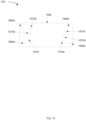
- FIG. 16A shows two access points, a first AP 1610 and a second AP 1620.
- the access points are in a first orientation with respect to each other.
- both the reference AP 1610 and the second AP 1620 are depicted as having only two antennas each in FIG. 16A .
- AP 1610 has antennas 1612 and 1614
- AP 1620 has antennas 1622 and 1624.
- Each one of these antennas is configured for receiving and/or transmitting signals at multiple different frequencies.
- the SPM commands the various transmitters on one AP to transmit signals at different frequencies to the other AP, determines the phase differences between signals received by any antenna pairs, and estimates the region/location in which the antennas of the second AP are located.
- FIG 16A shows the antenna locations of the second AP are estimated to be located within regions described by estimated antenna location 1623 and estimated antenna location 1625 respectfully.
- the position and orientation of the second AP is then estimated based on the estimated antenna location 1623 and estimated antenna location 1625. For example, some embodiments determine a best fit between a position and orientation of the second AP and the estimated antenna location 1623 and estimated antenna location 1625.
- the position and orientation of the second AP is estimated by minimizing a cumulative measure of the distance d1 1630 and the distance d2 1632.
- Distance d1 is a distance between the first antenna location 1622 and the estimated antenna location 1623
- distance d2 is a distance between the second antenna location 1624 and the estimated antenna location 1625.
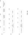
- FIG. 2D provides examples of data structures used by some embodiments to store layout information for a wireless device, such as an access point. Another example of the use of layout information is described above with respect to FIG. 3 .
- the function f(d i ) is a mean square of the distances function. In another embodiment the function f(d i ) is an absolute value. Other functions are contemplated by the disclosed embodiments.
- FIG. 16B shows a result of minimizing a function of the distances between estimated positions of the antennas while bringing into account the physical structure of the AP including the well-known relative locations of the antennas.
- FIG. 16B shows a second location and orientation between the reference AP 1610 and the second AP 1620.
- the second location and orientation 1600b minimizes a measure of distances d1 and d2, which were illustrated in FIG. 16A .
- the distances d1 and d2 are omitted from FIG. 16B but are a first distance between the first antenna location 1622 and estimated antenna location 1623 and a second distance between second antenna location 1624 and estimated antenna location 1625 respectively.
- the locations of the antennas of the second AP 1620 are determined to be location 1626 and location 1628 respectively.
- FIG. 16B shows that the second access point's position and orientation has been modified to provide for the reduced distances relative to distances d1 and d2 shown in FIG. 16A .
- the distance between the reference AP and the second AP as well as the relative orientations are determined.
- FIG. 17 is a two-dimensional example map 1700 illustrating a method of determining a location of a wireless transmitter based on phase differences between two receive elements.
- receive element 1710 and receive element 1715 are located at a distance of 3.5 ⁇ .
- Example transmitter T1 1720 is located in the middle between the two receive elements 1710 and 1715. Since the wireless transmitter is equidistant to both receive elements, the waveform at the two receive elements arrives with a phase difference of zero (0) degrees. Similarly, a waveform from any transmitter located on a straight line 1730 traverses the same distance to both receive elements and as such the phase difference between the signals received at the two receive elements is also zero degrees.
- transmitters T4 1723 and T5 1724 are located at a distance of ⁇ from transmitter T1. These transmitters are located at distances 0.75 ⁇ and 2.75 ⁇ from receive elements A1 and A2.
- the difference in the distance that the signals from these transmitters need to travel to reach the receive elements 1710 and 1715 compared with the distance that a waveform from T1 1720 needs to travel to reach the receive elements is one wavelength. Said otherwise, the difference in the arrival phase of transmitters in these locations at either receive element 1710 or receive element 1715 is two wavelengths. Therefore, the difference in the arrival phases in receive elements A1 and A2 is zero degrees.
- a waveform from any transmitter located on the hyperbolas 1732 or 1734 traverses the same distance to both receive elements and as such the phase difference between the signals received at the two receive elements is also zero degrees.
- Transmitters T2 1721 and T3 1722 are located at a distance of ⁇ /2 from transmitter T1. These transmitters are located at distances of 1.25 ⁇ and 2.25 ⁇ from receiver receive elements and therefore the signals from transmitters at these two locations arrive at either one of the receive elements A1 and A2 with a delay 1.25 ⁇ and phase difference of one wavelength. Also these transmitters are located at the same distance from receive elements A1 1710 and A2 1715 and as such the signals from these transmitters arrive at both receive elements at the same phase and the phase difference between the signals received at the two receive elements is therefore zero degrees. Similarly, for the same reason, a waveform from any transmitter located on hyperbolas passing through T2 and T3 would exhibit the same phase difference of zero degrees.
- Transmitters T6 1725 and T7 1726 are located at distances of 0.25 ⁇ and 3.25 ⁇ from receiver receive elements A1 and A2. Since a difference in distances from either transmitter 1725 or transmitter 1726 to any receive element is a multiple of the wavelength, signals would arrive at the two receive elements with the same phase, and thus a phase difference of zero (0) degrees. Similarly, a waveform from any transmitter located on hyperbolas passing through T6 and T7 would exhibit the same phase difference of zero degrees.
- phase differences of a waveform received at only two receive elements results in an infinite number of possible locations of the transmitter.
- Each of these infinite possible locations produce equivalent phase differences at the two receive elements.
- uncertainty remains in the location of the transmitter based on only these phase differences.
- some embodiments rely on more than two receive elements to increase certainty of location estimates.
- the additional phase differences provide additional independent information, which can assist in a more precise location determination of the wireless transmitter.
- FIG. 18 is a receiver topology 1800 that demonstrates determination of a location of a wireless transmitter based on phase differences at three receive elements.
- FIG. 18 shows a third receive element 1817 (labeled A3).
- receive elements A1 and A2 and the transmissions from locations T1 through T7 are similar to those previously discussed with respect to FIG. 17 .
- hyperbolas 1831, 1832, 1833, 1834, and 1835 describe locations from which transmission towards receive elements A1 and A2 arrive with equivalent phases (e.g. phase difference zero degrees).
- Receive element 1817 is added to the receiver topology 1800 and a phase difference between an arrival phase at A1 and at receive element A3 1817 is measured.
- T8 location 1840 T9 location 1841, T10 location 1842, T11 location 1843, T12 location 1844, location T13 1845, and T14 location 1846 which are located 0.5 ⁇ apart and T8 location 1840 is located 0.25 ⁇ away from receive element A1
- signals arriving from locations on the hyperbolas 1861, 1862, 1863, 1864 and 1865 have the same arrival phase. As such the difference between the arrival phase of the signals at A1 and A3 is zero.
- FIG. 18 indicates that, with two receive elements and a single transmission frequency, for any given phase delta there are numerous hyperbolas located at the same distances from the two receive elements. A waveform transmitted from any of these hyperbolas would result in signals received at antennas A1 and A2 with the same phase difference.
- a location of the wireless transmitter is further confined to locations that are also on new hyperbolas representing locations matching phased differences of receive elements A1 and A3.
- the illustrated phase differences at antennas A1 and A2 are zero and the phase differences at antennas A1 and A3 is also zero.
- the only locations from which the waveform may be transmitted must be located at the intersections of hyperbolas 1831, 1832, 1833, 1834, and 1835 (which is a straight line) with hyperbolas 1861, 1862, 1863, 1864, and 1865 (which is a straight line).
- the intersections between these hyperbolas correspond to line 1870.
- the line 1870 is at 45 degrees because this example is a special case wherein ⁇ of the signals at antennas A1 and A2 is zero and ⁇ of the signals at A1 and A3 is also zero. For any other non-identical ⁇ , the hyperbolas would intersect on a different line, thus indicating possible locations of the transmitter different from this example. The illustration so far took into account only a single frequency. Repeating the measurements using a different transmission frequency provides additional probable locations for each one of antennas. The system then determines the location and orientation of a second device by aggregating the estimated region/location based on difference of phase between any two antenna pairs and using one or more transmission frequencies.
- FIG. 18 indicates that by adding another receive element and collecting additional independent information about the phase differences of the signals, and specifically calculating the difference in phases, we further constrained the possible locations from which the wireless transmitter could have been located (and transmitted from) to result in ⁇ of the signals complying with a measured ⁇ .
- the system generates additional received signals with independent additional information about the location from which the wireless transmitter transmitted.
- measuring the difference in arrival phase of the signals received in A1, A2, A3, ....Ak, and determining the location that satisfies all of the hyperbolas results in determining the location of the wireless transmitter.
- the method described above is performed using different signal frequencies. Each frequency contributes additional measured phase differences as well as additional constraints that help narrow the specific location from which the transmitter operates..
- FIG. 19 is a map 1900 showing two receive elements and possible locations of an access point.
- FIG. 19 shows two wireless receivers 1902a and 1902b.
- FIG. 19 also shows three possible positions for a wireless transmitter (e.g. included in a wireless terminal, an access point, etc.), at 1904a, 1904b, and 1904c.
- FIG. 19 also shows a line 1905, each point on the line 1905 is equidistant from both of the receivers 1902a-b.
- a signal from a wireless transmitter such as any of the access points at positions 1904a- 1904b, and 1904c, will experience similar phase differences when received at a plurality of receive elements of each of the two receivers 1902a-b (e.g. zero).
- FIG. 20 is a map 2000 that is similar to that of FIG. 19 except two additional receivers are shown 1902c-d in addition to the two receivers 1902a-b.
- FIG. 20 shows that receivers 1902a and 1902b are equidistant from the transmitter (e.g., access point) located at position 1904b. These equal distances are shown as distances 1912a and 1912b.
- the position 1904b is a distance 1912c from a receiver 1902c and a distance 1912d from receiver 1902d.
- distance 1912c and distance 1912d are different than the distances 1912a-b, different phase differences of a waveform generated at position 1904c are experienced at receivers 1902c and 1902d, when compared to phase differences of the waveform when received at receivers 1902a and 1902b.
- differences in distances and the resulting phase differences relative to receivers 1902a-b assist some of the disclosed embodiments in identifying a position of a wireless transmitter located at position 1904b.
- a set of expected phase differences of a signal transmitted by a wireless transmitter at position 1904a (e.g. region centroid) when received at each pair of receive elements of the receivers 1902a-d are generated.
- a set of expected phase differences for a particular transmitter location and a particular receiver location are different from a second set of expected phase differences for a different transmitter location such as positions 1904a and 1904c, but the same particular receive location.
- when determining expected phase differences at a particular region or region centroid determine expected phase differences for multiple receivers or receive antennas. For example, in the example of FIG.
- each expected phase difference for a region or region centroid would include at least four sets of expected phase differences, one for each of the receivers.
- the number of expected phase differences for a region or region centroid would be at least, in these embodiments, the number of receive element pairs used in an embodiment times the number of frequencies used.
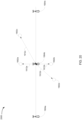
- FIG. 21 shows example positions of antennas of two access points in a two-dimensional space 2100. While the disclosed embodiments are capable of determining differences in access point orientation in each of up to three dimensions, for simplicity, FIG. 21 illustrates only a two-dimensional space. A Z axis is not shown.
- Example 13 the subject matter of Example 12 optionally includes the operations further comprising providing the aggregated location estimate to an advertising network.
- Example 28 the subject matter of Example 27 optionally includes the operations further comprising determining a best fit between the position estimates of the plurality of transmit elements, and relative positions of the plurality of transmit elements defined by the physical layout, wherein the determination of the second location and second orientation is based on the best fit.
- Example 29 the subject matter of Example 28 optionally includes wherein determining the best fit comprises: performing a first rotation of the physical layout of the transmit elements within a three-dimensional space; generating first candidate positions of the plurality of transmit elements based on the rotated physical layout; performing a first shift of the first candidate positions within the three-dimensional space; computing a first aggregation of distances between the position estimates of the plurality of transmit estimates and the shifted first candidate positions; performing a second rotation of the physical layout generating second candidate positions of the plurality of transmit elements based on the rotated physical layout; shifting the candidate positions within the three-dimensional space; computing a second aggregation of second distances between the position estimates of the plurality of transmit estimates and a different and comparing the first aggregation to the second aggregation, wherein the determining of the best fit is based on the comparing.
- mapping the second location estimate comprises: determining a relative location of the second wireless device with respect to the first wireless device, and adjusting the second location estimate of the third wireless device location estimate based on the relative location; and determining a relative orientation of the second wireless device with respect to the first wireless device, and adjusting the second location estimate of the third wireless device based on the relative orientation.
- Example 31 the subject matter of any one or more of Examples 26-30 optionally include wherein obtaining the third location estimate comprises determining probabilities that the third wireless device is within each of the first plurality of geographic regions, and aggregating the plurality of probabilities to obtain the first location estimate.
- Example 32 the subject matter of Example 31 optionally includes the operations further comprising: measuring second phase differences of signals from the third wireless device received at the receive elements of the first wireless device; determining first differences between the first phase differences and the expected phase differences for each of the first plurality of geographic regions; and determining, for each of the first plurality of geographic regions, a first probability that the third wireless device is located in each of the first plurality of geographic regions based on the geographic region's respective first difference, wherein the third location estimate is based on an aggregation of the determined first probabilities that the third wireless device is in each of the first plurality of geographic regions.
- Example 33 the subject matter of Example 32 optionally includes the operations further comprising: determining second estimated phase differences of signals received at the receive elements of the second wireless device, the signals transmitted from each of a second plurality of geographic regions defined in the second reference coordinate system, the second plurality of regions defined by the second wireless device; obtained measured phase differences of signals received at the receive elements of the second wireless device, the signals from the third wireless device; determining second differences between the measured phase differences and the second expected phase differences for each of the second plurality of geographic regions; and determining, for each of the second plurality of geographic regions, a second probability that the third wireless device is in the respective geographic region based on the geographic region's respective second difference, wherein the third location estimate is based on an aggregation of the determined second probabilities that the third wireless device is in each of the second plurality of geographic regions.
Landscapes
- Engineering & Computer Science (AREA)
- Computer Networks & Wireless Communication (AREA)
- Signal Processing (AREA)
- Physics & Mathematics (AREA)
- General Physics & Mathematics (AREA)
- Radar, Positioning & Navigation (AREA)
- Remote Sensing (AREA)
- Position Fixing By Use Of Radio Waves (AREA)
- Mobile Radio Communication Systems (AREA)
Applications Claiming Priority (4)
| Application Number | Priority Date | Filing Date | Title |
|---|---|---|---|
| US202062968754P | 2020-01-31 | 2020-01-31 | |
| US202063011851P | 2020-04-17 | 2020-04-17 | |
| US16/915,381 US11696092B2 (en) | 2020-01-31 | 2020-06-29 | Multi-wireless device location determination |
| EP20196872.4A EP3859370B1 (fr) | 2020-01-31 | 2020-09-18 | Détermination de l'emplacement de dispositifs sans fil multiples |
Related Parent Applications (1)
| Application Number | Title | Priority Date | Filing Date |
|---|---|---|---|
| EP20196872.4A Division EP3859370B1 (fr) | 2020-01-31 | 2020-09-18 | Détermination de l'emplacement de dispositifs sans fil multiples |
Publications (2)
| Publication Number | Publication Date |
|---|---|
| EP4530657A2 true EP4530657A2 (fr) | 2025-04-02 |
| EP4530657A3 EP4530657A3 (fr) | 2025-06-18 |
Family
ID=72521550
Family Applications (2)
| Application Number | Title | Priority Date | Filing Date |
|---|---|---|---|
| EP20196872.4A Active EP3859370B1 (fr) | 2020-01-31 | 2020-09-18 | Détermination de l'emplacement de dispositifs sans fil multiples |
| EP25154121.5A Withdrawn EP4530657A3 (fr) | 2020-01-31 | 2020-09-18 | Détermination de localisation de dispositif sans fil multiple |
Family Applications Before (1)
| Application Number | Title | Priority Date | Filing Date |
|---|---|---|---|
| EP20196872.4A Active EP3859370B1 (fr) | 2020-01-31 | 2020-09-18 | Détermination de l'emplacement de dispositifs sans fil multiples |
Country Status (6)
| Country | Link |
|---|---|
| US (3) | US11696092B2 (fr) |
| EP (2) | EP3859370B1 (fr) |
| JP (1) | JP2021125872A (fr) |
| CN (2) | CN121126369A (fr) |
| AU (1) | AU2020257056A1 (fr) |
| CA (1) | CA3090246A1 (fr) |
Families Citing this family (11)
| Publication number | Priority date | Publication date | Assignee | Title |
|---|---|---|---|---|
| US11422224B2 (en) | 2020-01-31 | 2022-08-23 | Juniper Networks, Inc. | Location determination based on phase differences |
| US11582710B2 (en) | 2020-01-31 | 2023-02-14 | Juniper Networks, Inc. | Guided alignment of wireless device orientation |
| US11696092B2 (en) | 2020-01-31 | 2023-07-04 | Juniper Networks, Inc. | Multi-wireless device location determination |
| US11843957B2 (en) | 2021-04-06 | 2023-12-12 | Juniper Networks, Inc. | Detection of insufficient RF coverage areas in a wireless network |
| US12484012B2 (en) | 2021-09-13 | 2025-11-25 | Juniper Networks, Inc. | Determining locations of deployed access points |
| US11811462B2 (en) | 2021-09-22 | 2023-11-07 | Qualcomm Incorporated | Base station location and orientation computation procedure |
| US12652546B1 (en) | 2022-04-21 | 2026-06-09 | Hewlett Packard Enterprise Development Lp | Systems and methods of determining floor locations of deployed access points |
| US12580836B2 (en) | 2022-06-30 | 2026-03-17 | Juniper Networks, Inc. | Orchestration of round-trip time (RTT) measurements |
| US20240224165A1 (en) | 2022-12-30 | 2024-07-04 | Juniper Networks, Inc. | Automatic grouping of deployed access points |
| DE102024110705A1 (de) * | 2024-04-17 | 2025-10-23 | Friedrich-Alexander Universität Erlangen-Nürnberg, Körperschaft des öffentlichen Rechts | Verfahren zum Bestimmen einer Position und einer Ausrichtung eines Empfängerarrays durch Schätzung |
| US20260239284A1 (en) | 2025-02-10 | 2026-08-13 | Juniper Networks, Inc. | Location determination based on a plurality of directional beams |
Family Cites Families (42)
| Publication number | Priority date | Publication date | Assignee | Title |
|---|---|---|---|---|
| US6249252B1 (en) | 1996-09-09 | 2001-06-19 | Tracbeam Llc | Wireless location using multiple location estimators |
| US5852630A (en) | 1997-07-17 | 1998-12-22 | Globespan Semiconductor, Inc. | Method and apparatus for a RADSL transceiver warm start activation procedure with precoding |
| US6243587B1 (en) | 1997-12-10 | 2001-06-05 | Ericsson Inc. | Method and system for determining position of a mobile transmitter |
| US20040198386A1 (en) | 2002-01-16 | 2004-10-07 | Dupray Dennis J. | Applications for a wireless location gateway |
| CA2296812A1 (fr) | 1999-02-17 | 2000-08-17 | Lucent Technologies Inc. | Methode pour combiner des mesures multiples afin de determiner la position d'un emetteur-recepteur mobile |
| GB2347571A (en) | 1999-03-03 | 2000-09-06 | Secr Defence | Locating system |
| US6489923B1 (en) | 1999-09-16 | 2002-12-03 | Nortel Networks Limited | Position location method and apparatus for a mobile telecommunications system |
| US6255991B1 (en) | 2000-01-19 | 2001-07-03 | Trw Inc. | Low cost angle of arrival measurement system |
| US6362782B1 (en) | 2000-04-19 | 2002-03-26 | The Charles Stark Draper Laboratories, Inc. | Multipath propagation detection and avoidance method and system |
| US6408246B1 (en) | 2000-10-18 | 2002-06-18 | Xircom Wireless, Inc. | Remote terminal location algorithm |
| US20050088337A1 (en) | 2001-10-01 | 2005-04-28 | Thales North America, Inc. | Vertically stacked turnstile array |
| US6748324B2 (en) * | 2002-01-07 | 2004-06-08 | Motorola, Inc. | Method for determining location information |
| US7711375B2 (en) | 2002-08-06 | 2010-05-04 | Hang Liu | Method and system for determining a location of a wireless transmitting device and guiding the search for the same |
| AU2003278834A1 (en) | 2002-09-18 | 2004-04-08 | Incucomm, Inc. | Control processor for use with a transceiver in an optical wireless network |
| US7489935B2 (en) | 2003-05-19 | 2009-02-10 | Michigan Technological University | Wireless local positioning system |
| US7856209B1 (en) * | 2003-12-08 | 2010-12-21 | Airtight Networks, Inc. | Method and system for location estimation in wireless networks |
| US9282446B2 (en) * | 2009-08-06 | 2016-03-08 | Golba Llc | Location-aware content and location-based advertising with a mobile device |
| US20080191941A1 (en) * | 2007-02-12 | 2008-08-14 | Mobileaccess Networks Ltd. | Indoor location determination |
| US7436359B1 (en) | 2007-05-30 | 2008-10-14 | Northrop Grumman Systems Corporation | Method for single satellite geolocation of emitters using an ambiguous interferometer array |
| US8264409B2 (en) | 2009-01-30 | 2012-09-11 | The United States Of America As Represented By The Secretary Of The Navy | Electromagnetic radiation source locating system |
| US9151822B2 (en) | 2009-12-31 | 2015-10-06 | Optimal Ranging, Inc. | Precise positioning using a distributed sensor network |
| US10482475B2 (en) | 2011-02-10 | 2019-11-19 | Adp Dealer Services, Inc. | Systems and methods for providing targeted advertising |
| US9674661B2 (en) * | 2011-10-21 | 2017-06-06 | Microsoft Technology Licensing, Llc | Device-to-device relative localization |
| US8457684B2 (en) | 2011-10-24 | 2013-06-04 | Arieso Limited | Method and apparatus for determining the location of a femtocell |
| US9191798B2 (en) * | 2012-03-09 | 2015-11-17 | Nokia Technologies Oy | Methods, apparatuses, and computer program products for saving and resuming a state of a collaborative interaction session between devices based on their positional relationship |
| US9310461B2 (en) | 2013-03-15 | 2016-04-12 | Cisco Technology, Inc. | Determining access point orientation based on neighbor access point locations |
| GB201401580D0 (en) | 2014-01-30 | 2014-03-19 | Ucl Business Plc | Apparatus and method for calibrating a wireless access point comprising an array of multiple antennas |
| EP2985624B1 (fr) | 2014-08-13 | 2021-03-10 | Deutsche Telekom AG | Procédé et dispositifs de détermination de l'orientation d'un dispositif de communication mobile |
| US20160084937A1 (en) | 2014-09-22 | 2016-03-24 | Invensense Inc. | Systems and methods for determining position information using acoustic sensing |
| US10036638B2 (en) * | 2016-06-07 | 2018-07-31 | NinthDecimal, Inc. | Systems and methods of tracking locations visited by mobile devices residing within a predetermined activity area to quantify a change |
| US11212647B2 (en) * | 2015-01-12 | 2021-12-28 | Qualcomm Incorporated | Location reporting of a wireless device |
| US10247808B2 (en) | 2015-01-12 | 2019-04-02 | Qualcomm Incorporated | Location reporting for extremely high frequency (EHF) devices |
| US11550024B2 (en) * | 2016-09-20 | 2023-01-10 | Deeyook Location Technologies Ltd. | Interferometric location sensing |
| US10877160B2 (en) | 2018-02-26 | 2020-12-29 | Cisco Technology, Inc. | Compensating for access point orientation errors with respect to a predefined area orientation |
| JP6775541B2 (ja) | 2018-04-03 | 2020-10-28 | 株式会社Subaru | 位置計測方法及び位置計測システム |
| WO2019221746A1 (fr) | 2018-05-18 | 2019-11-21 | Ensco, Inc. | Système, appareil et procédé de suivi de position et d'orientation |
| US11086124B2 (en) * | 2018-06-13 | 2021-08-10 | Reavire, Inc. | Detecting velocity state of a device |
| US10547974B1 (en) * | 2019-03-19 | 2020-01-28 | Microsoft Technology Licensing, Llc | Relative spatial localization of mobile devices |
| US11582710B2 (en) | 2020-01-31 | 2023-02-14 | Juniper Networks, Inc. | Guided alignment of wireless device orientation |
| US11696092B2 (en) | 2020-01-31 | 2023-07-04 | Juniper Networks, Inc. | Multi-wireless device location determination |
| US11778418B2 (en) | 2020-01-31 | 2023-10-03 | Juniper Networks, Inc. | Aligned multi-wireless device location determination |
| US11422224B2 (en) | 2020-01-31 | 2022-08-23 | Juniper Networks, Inc. | Location determination based on phase differences |
-
2020
- 2020-06-29 US US16/915,381 patent/US11696092B2/en active Active
- 2020-08-17 CA CA3090246A patent/CA3090246A1/fr not_active Abandoned
- 2020-08-24 JP JP2020140768A patent/JP2021125872A/ja active Pending
- 2020-09-18 EP EP20196872.4A patent/EP3859370B1/fr active Active
- 2020-09-18 CN CN202511296400.6A patent/CN121126369A/zh active Pending
- 2020-09-18 EP EP25154121.5A patent/EP4530657A3/fr not_active Withdrawn
- 2020-09-18 CN CN202010988316.1A patent/CN113207131B/zh active Active
- 2020-10-20 AU AU2020257056A patent/AU2020257056A1/en not_active Abandoned
-
2023
- 2023-05-25 US US18/324,074 patent/US12052634B2/en active Active
-
2024
- 2024-07-26 US US18/785,312 patent/US20240388871A1/en active Pending
Also Published As
| Publication number | Publication date |
|---|---|
| JP2021125872A (ja) | 2021-08-30 |
| US12052634B2 (en) | 2024-07-30 |
| CN113207131B (zh) | 2025-09-23 |
| EP4530657A3 (fr) | 2025-06-18 |
| CA3090246A1 (fr) | 2021-07-31 |
| US20240388871A1 (en) | 2024-11-21 |
| US20230308834A1 (en) | 2023-09-28 |
| CN121126369A (zh) | 2025-12-12 |
| EP3859370B1 (fr) | 2025-01-29 |
| US20210243558A1 (en) | 2021-08-05 |
| US11696092B2 (en) | 2023-07-04 |
| AU2020257056A1 (en) | 2021-08-19 |
| EP3859370A1 (fr) | 2021-08-04 |
| CN113207131A (zh) | 2021-08-03 |
Similar Documents
| Publication | Publication Date | Title |
|---|---|---|
| EP3859370B1 (fr) | Détermination de l'emplacement de dispositifs sans fil multiples | |
| EP3859368B1 (fr) | Détermination d'emplacement basé sur des différences de phase | |
| EP3859369B1 (fr) | Détermination de l'emplacement de dispositifs multi-sans fil alignés | |
| EP3859371B1 (fr) | Alignement guidé de l'orientation d'un dispositif sans fil | |
| US9578466B2 (en) | Method for indoor localization using nomadic access points | |
| Lee et al. | Bilatangulation: A Novel Measurement Error Compensation Method for Wi-Fi Indoor Positioning With Two Anchors |
Legal Events
| Date | Code | Title | Description |
|---|---|---|---|
| PUAI | Public reference made under article 153(3) epc to a published international application that has entered the european phase |
Free format text: ORIGINAL CODE: 0009012 |
|
| STAA | Information on the status of an ep patent application or granted ep patent |
Free format text: STATUS: THE APPLICATION HAS BEEN PUBLISHED |
|
| AC | Divisional application: reference to earlier application |
Ref document number: 3859370 Country of ref document: EP Kind code of ref document: P |
|
| AK | Designated contracting states |
Kind code of ref document: A2 Designated state(s): AL AT BE BG CH CY CZ DE DK EE ES FI FR GB GR HR HU IE IS IT LI LT LU LV MC MK MT NL NO PL PT RO RS SE SI SK SM TR |
|
| REG | Reference to a national code |
Ref country code: DE Ref legal event code: R079 Free format text: PREVIOUS MAIN CLASS: G01S0003480000 Ipc: G01S0005060000 |
|
| PUAL | Search report despatched |
Free format text: ORIGINAL CODE: 0009013 |
|
| AK | Designated contracting states |
Kind code of ref document: A3 Designated state(s): AL AT BE BG CH CY CZ DE DK EE ES FI FR GB GR HR HU IE IS IT LI LT LU LV MC MK MT NL NO PL PT RO RS SE SI SK SM TR |
|
| RIC1 | Information provided on ipc code assigned before grant |
Ipc: G01S 3/48 20060101ALN20250513BHEP Ipc: G01S 5/06 20060101AFI20250513BHEP |
|
| STAA | Information on the status of an ep patent application or granted ep patent |
Free format text: STATUS: REQUEST FOR EXAMINATION WAS MADE |
|
| 17P | Request for examination filed |
Effective date: 20251215 |
|
| STAA | Information on the status of an ep patent application or granted ep patent |
Free format text: STATUS: EXAMINATION IS IN PROGRESS |
|
| STAA | Information on the status of an ep patent application or granted ep patent |
Free format text: STATUS: THE APPLICATION HAS BEEN WITHDRAWN |
|
| 17Q | First examination report despatched |
Effective date: 20260608 |
|
| 18W | Application withdrawn |
Effective date: 20260624 |