EP4530652A1 - Antennenanordnung für hochfrequenzempfänger - Google Patents
Antennenanordnung für hochfrequenzempfänger Download PDFInfo
- Publication number
- EP4530652A1 EP4530652A1 EP23200724.5A EP23200724A EP4530652A1 EP 4530652 A1 EP4530652 A1 EP 4530652A1 EP 23200724 A EP23200724 A EP 23200724A EP 4530652 A1 EP4530652 A1 EP 4530652A1
- Authority
- EP
- European Patent Office
- Prior art keywords
- radio frequency
- operational mode
- pulses
- controlling unit
- receiver coil
- Prior art date
- Legal status (The legal status is an assumption and is not a legal conclusion. Google has not performed a legal analysis and makes no representation as to the accuracy of the status listed.)
- Pending
Links
- 238000002595 magnetic resonance imaging Methods 0.000 claims abstract description 215
- 230000004044 response Effects 0.000 claims abstract description 35
- 230000002123 temporal effect Effects 0.000 claims description 119
- 230000005540 biological transmission Effects 0.000 claims description 30
- 238000000034 method Methods 0.000 claims description 29
- 238000004458 analytical method Methods 0.000 claims description 17
- 238000004590 computer program Methods 0.000 claims description 13
- 230000001960 triggered effect Effects 0.000 claims description 8
- 238000010801 machine learning Methods 0.000 description 45
- 238000001208 nuclear magnetic resonance pulse sequence Methods 0.000 description 33
- 238000003860 storage Methods 0.000 description 20
- 238000012545 processing Methods 0.000 description 15
- 238000012549 training Methods 0.000 description 15
- 238000003384 imaging method Methods 0.000 description 10
- 230000006870 function Effects 0.000 description 8
- 230000013016 learning Effects 0.000 description 7
- 230000008569 process Effects 0.000 description 7
- 238000010586 diagram Methods 0.000 description 6
- 230000000712 assembly Effects 0.000 description 5
- 238000000429 assembly Methods 0.000 description 5
- 230000009286 beneficial effect Effects 0.000 description 4
- 238000009826 distribution Methods 0.000 description 4
- 230000005669 field effect Effects 0.000 description 4
- 230000003287 optical effect Effects 0.000 description 4
- 230000005284 excitation Effects 0.000 description 3
- 230000003252 repetitive effect Effects 0.000 description 3
- 238000013528 artificial neural network Methods 0.000 description 2
- 239000003990 capacitor Substances 0.000 description 2
- 238000004891 communication Methods 0.000 description 2
- 230000008878 coupling Effects 0.000 description 2
- 238000010168 coupling process Methods 0.000 description 2
- 238000005859 coupling reaction Methods 0.000 description 2
- 238000001514 detection method Methods 0.000 description 2
- 230000000694 effects Effects 0.000 description 2
- 230000000644 propagated effect Effects 0.000 description 2
- 230000000638 stimulation Effects 0.000 description 2
- 238000012706 support-vector machine Methods 0.000 description 2
- 238000013526 transfer learning Methods 0.000 description 2
- 230000003213 activating effect Effects 0.000 description 1
- 238000003491 array Methods 0.000 description 1
- 230000008901 benefit Effects 0.000 description 1
- 230000008094 contradictory effect Effects 0.000 description 1
- 238000013527 convolutional neural network Methods 0.000 description 1
- 238000003066 decision tree Methods 0.000 description 1
- 238000013135 deep learning Methods 0.000 description 1
- 230000001419 dependent effect Effects 0.000 description 1
- 238000002059 diagnostic imaging Methods 0.000 description 1
- 230000008676 import Effects 0.000 description 1
- 230000000977 initiatory effect Effects 0.000 description 1
- 238000012417 linear regression Methods 0.000 description 1
- 239000004973 liquid crystal related substance Substances 0.000 description 1
- 238000004519 manufacturing process Methods 0.000 description 1
- 238000013178 mathematical model Methods 0.000 description 1
- 239000013307 optical fiber Substances 0.000 description 1
- 230000002787 reinforcement Effects 0.000 description 1
- 230000035945 sensitivity Effects 0.000 description 1
- 230000008054 signal transmission Effects 0.000 description 1
- 210000003813 thumb Anatomy 0.000 description 1
- 230000000007 visual effect Effects 0.000 description 1
Images


Classifications
-
- G—PHYSICS
- G01—MEASURING; TESTING
- G01R—MEASURING ELECTRIC VARIABLES; MEASURING MAGNETIC VARIABLES
- G01R33/00—Arrangements or instruments for measuring magnetic variables
- G01R33/20—Arrangements or instruments for measuring magnetic variables involving magnetic resonance
- G01R33/28—Details of apparatus provided for in groups G01R33/44 - G01R33/64
- G01R33/32—Excitation or detection systems, e.g. using radio frequency signals
- G01R33/36—Electrical details, e.g. matching or coupling of the coil to the receiver
- G01R33/3642—Mutual coupling or decoupling of multiple coils, e.g. decoupling of a receive coil from a transmission coil, or intentional coupling of RF coils, e.g. for RF magnetic field amplification
- G01R33/3657—Decoupling of multiple RF coils wherein the multiple RF coils do not have the same function in MR, e.g. decoupling of a transmission coil from a receive coil
-
- G—PHYSICS
- G01—MEASURING; TESTING
- G01R—MEASURING ELECTRIC VARIABLES; MEASURING MAGNETIC VARIABLES
- G01R33/00—Arrangements or instruments for measuring magnetic variables
- G01R33/20—Arrangements or instruments for measuring magnetic variables involving magnetic resonance
- G01R33/28—Details of apparatus provided for in groups G01R33/44 - G01R33/64
- G01R33/32—Excitation or detection systems, e.g. using radio frequency signals
- G01R33/36—Electrical details, e.g. matching or coupling of the coil to the receiver
- G01R33/3692—Electrical details, e.g. matching or coupling of the coil to the receiver involving signal transmission without using electrically conductive connections, e.g. wireless communication or optical communication of the MR signal or an auxiliary signal other than the MR signal
Definitions
- the invention relates to magnetic resonance imaging, in particular to a radio frequency receiver antenna assembly comprising a radio frequency receiver coil for magnetic resonance imaging, a magnetic resonance imaging system comprising the radio frequency receiver antenna assembly, a computer program comprising machine executable instructions for execution by a computational component of a controlling unit of the radio frequency receiver antenna assembly, and a method for controlling the radio frequency receiver antenna assembly.
- radio frequency (RF) receiver coils are tuned to be sensitive for a resonance frequency of nuclei being excited in a target zone of the MRI system, i.e., the Larmor frequency of nuclei to be imaged.
- RF pulses are transmitted at the resonance frequency, i.e., using the resonance frequency as a carrier frequency.
- large amounts of power at the resonance frequency may be transmitted by the RF pulses.
- a temporary detuning of the RF receiver coils during the transmission of the RF pulses may be required, in order to protect the RF receiver coils and associated circuitry from such large amounts of power and to avoid transmit field distortions due to eddy currents which also come with risks for the patient.
- the coils may temporarily be switched to a detuned operational mode, in which they are not tuned to the resonance frequency anymore and a sensitivity for the RF field (B 1 ) transmitting the pulses is reduced.
- a switching between the tuned operational mode and the detuned operational mode may, e.g., be controlled by an MRI backend via a dedicated tuning line, i.e., cable, transmitting commands to the receiver coils, in order to switch the same between the tuned operational mode and the detuned operational mode.
- such a dedicated tuning line may by itself cause further problems like a coupling to MRI transmitting and/or receiving fields resulting in negative effects on patient safety and/or image quality.
- the radio frequency receiver antenna assembly is configured for:
- the detuning assembly may reduce that signal power level of a received signal by, e.g., just around 20 to 45 dB.
- Electronically "detuning" the RF receiver coil briefly during RF pulse transmission may prevent problems with the RF receiver coil, e.g., from being burned out by powerful RF pulses.
- the controlling unit uses the controlling unit to implement an intelligent local control of a switching of the receiver coil between different operational modes.
- the controlling unit is inter alia configured as a switch driver for operating the switch, in order to switch the receiver coil between the tuned operational mode and the detuned operational mode.
- the switch may, e.g., comprise a PIN (positive intrinsic negative) diode, a FET (field-effect transistor), a MEM (micro-electro-mechanical) switch or the like for switching.
- the RF receiver antenna assembly is configured receive via the RF receiver coil wireless RF signals, which provide the controlling unit with information that enable the controlling unit to determining a control sequence for an MRI sequence.
- the control sequence is used by the controlling unit to control the switch of the detuning assembly, such that the receiver coil is operated in the detuned operational mode during a transmission of the pulses of the respective MRI sequence and in the tuned operational mode during the rest of the MRI sequence.
- the wireless RF signals comprise at least a wireless RF definition signal providing information, which enables the controlling unit to determine the control sequence.
- the wireless RF definition signal may, e.g., describe the MRI sequence for which the control sequence is to be determined and/or it may, e.g., describe the control sequence to be used for controlling the switch, while the MRI sequence is received.
- the wireless RF signals further comprise a wireless RF trigger signal triggering the controlling unit to execute the control sequence, i.e., to switch the RF receiver coil between the tuned operational mode and the detuned operational mode according to the control sequence.
- This trigger signal may be used for synchronizing the execution of the control sequence with a transmission of the MRI sequence.
- the wireless RF definition signal and/or the wireless RF trigger signal may, e.g., be provided in form of the pulses according to a pulse sequence.
- the controlling unit may, e.g., comprise a digital receiver.
- the digital receiver may, e.g., be configured for amplifying the RF signals received via the RF receiver coil, e.g., using a low-noise preamplifier, for digitizing analog RF signals received via the RF receiver coil using a high frequency analog-to-digital converter (ADC), and/or for demodulating the RF signals received via the RF receiver coil, i.e., extracting information from the RF signals.
- the digital receiver may be configured to detect and process the RF definition signal and the RF trigger signal received as wireless signals via the RF receiver coil, e.g., when the receiver coil is operated in the detuned operational mode.
- the RF receiver antenna assembly may, e.g., comprise a single RF receiver coil being switched by the controlling unit using the determined controlling sequence.
- the RF receiver antenna assembly may, e.g., comprise a plurality of two or more RF receiver coils being switched by the controlling unit using the determined controlling sequence.
- the controlling unit may be configured to operate the switch of the detuning assembly based on the control sequence determined using the received wireless RF definition signal, e.g., an RF transmit field comprising pulses according to a pulse sequence.
- the controlling unit may further be configured to infer an upcoming transmit pulse pattern using the received wireless RF trigger signal, e.g., an RF transmit field comprising pulses according to a pulse sequence.
- the RF receiver antenna assembly may, e.g., be configured for detecting a transmit pulse sequence automatically using the RF receiver coil and the controlling unit as well as for switching between operational modes on its own using the control sequence.
- Examples may have the beneficial that an amount of cabling to the RF receiver antenna assembly may be reduced. For example, a need for an additional cabling to the RF receiver antenna assembly to transmit control signals for controlling a switching of the RF receiver coil between the tuned operational mode and the detuned operational mode may be avoided. Any signals, e.g., the definition signal and the trigger signal, may be received in form of wireless RF signals via the RF receiver coils to the RF receiver antenna assembly.
- no signal transmission line to the RF receiver antenna assembly may be required.
- Data required by the controlling unit may, e.g., be transmitted exclusively in wireless form using the abilities of the receiver antenna assembly.
- no data may be transmitted from an MRI backend to the receiver antenna assembly via wires.
- data may only be transmitted via wires from the receiver antenna assembly to the MRI backend.
- This wire-based transmission data are the MRI receive signals, i.e., acquired MRI data, which are transmitted in analog or digital form from the receiving receiver antenna assembly to the MRI backend of the MRI system, i.e., to a data processing unit of the MRI system for further processing.
- This further processing may, e.g., comprise generating images using the acquired MRI data.
- the control sequence may define when to switch between the tuned operational mode and the detuned operational mode.
- the control sequence may define an alternating sequence between the tuned operational mode and the detuned operational mode.
- the control sequence may define lengths of temporal intervals during which the RF receiver coil is to be operated in the tuned operational mode or the detuned operational mode, while an MRI sequence of an MRI RF signal is received.
- the control sequence for a pulse sequence may define temporal intervals during which pulses of the MRI sequence are transmitted and the RF receiver coil is to be operated in the detuned operational mode as well as temporal intervals during which no pulses of the MRI sequence are transmitted and the RF receiver coil is to be operated in the tuned operational mode.
- the wireless RF trigger signal may, e.g., comprise the MRI sequence defined by the wireless RF definition signal.
- the wireless RF trigger signal may, e.g., not comprise the MRI sequence.
- the wireless RF trigger signal may, e.g., comprise a trigger assigned to the MRI sequence and/or to a starting of a transmission of the MRI sequence.
- a trigger assigned to the MRI sequence may, e.g., be an MRI sequence ID.
- a trigger indicative of a starting of a transmission of the MRI sequence may, e.g., be a switching of a carrier frequency of an RF signal being received, e.g., the RF definition signal, from a non-resonant frequency to a resonance MRI frequency.
- a start of the control sequence may be defined relative to a reception of the wireless RF trigger signal.
- the wireless RF trigger signal may be used for a synchronization of the execution of the control sequence with an MRI data acquisition procedure executed by an MRI system comprising the RF receiver antenna assembly.
- the wireless RF trigger signal may be a dedicated synchronization signal indicating an immediate start of a transmission of an MRI sequence or a start of the transmission after a pre-defined period of time.
- the wireless RF trigger signal may be provided in form of switching of a carrier frequency of an RF signal received by the RF receiver coil from a non-resonant frequency to a resonance MRI frequency.
- the switching of the carrier frequency may indicate the start of the MRI sequence. While using the non-resonant RF frequency nuclei within a target zone of an MRI system may not be excited. When switching the resonance RF frequency, the nuclei may be excited and an MRI data acquisition may be start.
- control sequence may define a prospective sequence of switching between the tuned operational mode and the detuned operational mode of the receiver coil in response to the receiving of the wireless RF definition signal and start the execution of the control sequence in response to the receiving of the wireless RF trigger signal.
- Examples may enable a switching of the receiver coil between the detuned operational mode and the tuned operational mode based on a temporal pattern of pulses determined for an MRI sequence using the RF definition signal.
- the pattern to be used may already be determined using an onset of a wireless RF signal received via the receiver coil.
- an end of the respective RF signal i.e., a first transmission or a repetitive transmission of the RF signal may be used as a trigger for triggering the controlling unit of the RF receiver antenna assembly to execute the determined control sequence during reception of one or more repetitions of the respective RF signal.
- a prospective definition of a required switching between the tuned operational mode and the detuned operational mode of the receiver coil in form of the control sequence may be used.
- the control sequence may define a prospective switching pattern, which is executed in response to the reception of the RF trigger signal.
- the determining of the control sequence comprises determining a temporal pattern of pulses of the MRI sequence using the wireless radio frequency definition signal.
- the determined temporal pattern of pulses is used for the determining of the control sequence.
- the determined temporal pattern of pulses may comprise one or more of the following features determined by the controlling unit using the received RF definition signal: values describing a relative temporal distribution of the pulses, values describing temporal durations of the pulses and/or a value describing a temporal length of the MRI sequence.
- the wireless radio frequency definition signal comprises the MRI sequence.
- the MRI sequence is used for the determining of the temporal pattern of pulses.
- the MRI sequence may, e.g., be transmitted using a non-resonant carrier frequency.
- the controlling unit may be configured to analyze the MRI sequence and determine one or more features of the MRI sequence and/or the temporal pattern of pulses of the MRI sequence. These features may, e.g., comprise values describing a relative temporal distribution of the pulses, values describing temporal durations of the pulses and/or a value describing a temporal length of the MRI sequence.
- the determined features of the MRI sequence and/or the temporal pattern of pulses of the MRI sequence may be used to determine the temporal pattern of pulses.
- the RF receiver antenna assembly comprises the controlling unit for controlling the RF receiver coil.
- the controlling unit analyzes the MRI sequence comprised by the wireless RF definition signal and determines the control sequence based on the result of the analysis to be used for a tuning and detuning of the receiver coil.
- MRI sequences may show a repetitive pattern
- an MRI RF signal may comprise one or more repetitions of the MRI sequence.
- the controlling unit may, e.g., determine the pattern of the pulse sequence, i.e., the temporal pattern of pulses, from a first run. This first run may be the wireless RF definition signal. Then, the controlling unit may switch the receiver coil automatically according to the control sequence determined using the temporal pattern of pulses acquired from the first run. According to the control sequence, the receiver coil may be switched to the detuned operational mode during the pulses and to the tuned operational mode during the acquisition phase.
- the pulse sequence may be detected during the first run for a complete series of pulses to synchronize the controlling unit to the exact clock of the pulses.
- this first run i.e., the first pulse sequence may not be used for imaging purposes, since the receiver coil may not be operated in the tuned operational mode during the receiving of the wireless RF definition signal, i.e., the first run.
- the first pulse sequence may be an additional pulse sequence sent before sending the actual pulse sequences for imaging purposes.
- This additional pulse sequence, i.e., the wireless RF definition signal may, e.g., be sent using a non-resonant RF frequency outside an MRI RF bandwidth to avoid exciting nuclei in a target zone of the MRI system during transmission of the additional pulse sequence.
- a switching from the non-resonant RF frequency to a resonance RF frequency within the MRI RF bandwidth may trigger the controlling unit as an RF trigger signal to execute the control sequence.
- the wireless radio frequency definition signal further comprises at least one repetition of the MRI sequence.
- the wireless radio frequency definition signal further comprises a plurality of repetitions of the MRI sequence.
- control unit may comprise a machine learning module trained to output a control sequence in response to receiving an MRI sequence.
- the MRI sequence may be provided as input to the machine learning module by the controlling unit.
- the MRI sequence may be provided by the wireless RF definition signal received by the controlling unit via the RF receiver coil.
- the machine learning module may, e.g., be stored in a memory comprised by the controlling unit.
- the machine learning module may be trained to predict a control sequence as an output for an MRI sequence as an input.
- an untrained or partially pre-trained machine learning module to be trained may be provided.
- the machine learning module to be trained may be trained using training datasets.
- Each training dataset may, e.g., comprise a training MRI sequence to be used as a training input and a training control sequence to be used as training output.
- the machine learning module is trained using the training datasets to provide the training control sequences as output in response to receiving the corresponding training MRI sequences as input.
- the resulting trained machine learning module is configured to output a control sequence in response to receiving an MRI sequence as input.
- Examples may implement a machine learning based switch control by the controlling unit using the machine learning module.
- This machine learning based switch control may be configured to return a switch control signal for controlling the switch of the detuning assembly in form of the control sequence from the wireless RF definition signal comprising an MRI sequence, which is received via the RF receiver coil.
- the machine learning module may be used for estimating a control sequence for a temporal pattern of pulses.
- the wireless RF definition signal may, e.g., comprise one or more definitions of one or more features of the MRI sequence and/or the temporal pattern of pulses of the MRI sequence. These features may, e.g., comprise values describing a relative temporal distribution of the pulses, values describing temporal durations of the pulses and/or a value describing a temporal length of the MRI sequence.
- the received features of the MRI sequence and/or the temporal pattern of pulses of the MRI sequence may be used to determine the temporal pattern of pulses.
- the controlling unit is configured to decode the one or more features of the temporal pattern of pulses using one or more of the following: an amplitude modulation analysis, a frequency modulation analysis, a Manchester code analysis, a pulse-width modulation analysis.
- the controlling unit may be configured to decode the one or more features of the temporal pattern of pulses using an amplitude modulation analysis, a frequency modulation analysis, a Manchester code analysis, and/or a pulse-width modulation analysis of the wireless RF signal received via the RF receiver coil.
- the controlling unit comprises a memory.
- One or more additional features of the temporal pattern of pulses are pre-stored in the memory.
- the pre-stored one or more additional features of the temporal pattern of pulses is used for the determining of the temporal pattern of pulses.
- Additional features may, e.g., comprise values describing a relative temporal distribution of the pulses, values describing temporal durations of the pulses and/or a value describing a temporal length of the MRI sequence.
- the additional features of the temporal pattern of pulses of the MRI sequence may be used to determine the temporal pattern of pulses.
- the determined temporal pattern of pulses may be assigned to the determined control sequence.
- the controlling unit may detect the temporal pattern of pulses of the wireless RF trigger signal, i.e., a transmit pulse sequence being used for MRI data acquisition, automatically and switch the receiver coil between the tuned operational mode and the detuned operational mode using the control sequence without requiring further input.
- the wireless RF trigger signal is received after the wireless radio frequency definition signal.
- the RF trigger signal may, e.g., be equal to the RF definition signal.
- Both signals may, e.g., comprise the MRI sequence.
- a first transmission of the MRI sequence may be used as the RF definition signal for determining the temporal pattern of pulses as well as the control sequence.
- the temporal pattern of pulses may be assigned to the control sequence.
- a second transmission of the MRI sequence may, e.g., be used as the RF trigger signal.
- the controlling unit is triggered to execute the assigned control sequence.
- a plurality of different temporal patterns of pulses as well as different control sequences may be determined for a plurality of different RF definition signals.
- the determined pairs of control sequences and assigned temporal patterns of pulses may, e.g., be stored in a memory of the controlling unit.
- a temporal pattern of pulses of the MRI sequence is determined by the controlling unit and compared to the stored temporal patterns of pulses.
- the controlling unit may select the control sequence, to which the matching temporal pattern of pulses is assigned.
- the selected control sequence may be used by the controlling unit for switching the receiver coil loop between the tuned operational mode and the detuned operational mode.
- the receiving of the wireless radio frequency trigger signal comprises determining a switching of a carrier frequency of a received RF signal from a non-resonant frequency of the RF definition signal to a resonance frequency of an MRI RF signal.
- the switching of frequency may be the RF trigger signal triggering the controlling unit.
- the wireless radio frequency trigger signal is the wireless radio frequency definition signal defining the temporal pattern of pulses and triggering the switching of the receiver coil.
- the switching of the receiver coil according to the control sequence is triggered automatically at an end of the receiving of the wireless radio frequency definition signal.
- the RF trigger signal may, e.g., be a dedicated signal indicating a start of an MRI RF pulse signal.
- the RF trigger signal may be a switching of a carrier sequence.
- the RF trigger signal may comprise a trigger encoded in the wireless RF trigger signal.
- the controlling unit may be configured to decode the trigger using the wireless RF trigger signal.
- the controlling unit is configured to decode the trigger using one or more of the following: an amplitude modulation analysis, a frequency modulation analysis, a Manchester code analysis, a pulse-width modulation analysis.
- the magnetic resonance imaging system is configured to transmit the wireless RF definition signal and/or the wireless RF trigger signal at a radio frequency outside a pre-defined MRI frequency bandwidth used by the MRI system for exciting nuclei within the target zone of the MRI system.
- Execution of the machine executable instructions by the computational component causes the computational component to control the radio frequency receiver antenna assembly to:
- the method may be configured for controlling any of the aforementioned examples of an RF receiver antenna assembly.
- aspects of the present invention may be embodied as an apparatus, method or computer program product. Accordingly, aspects of the present invention may take the form of an entirely hardware embodiment, an entirely software embodiment (including firmware, resident software, micro-code, etc.) or an embodiment combining software and hardware aspects that may all generally be referred to herein as a "circuit", "module” or “system”. Furthermore, aspects of the present invention may take the form of a computer program product embodied in one or more computer readable medium(s) having computer executable code embodied thereon.
- the computer readable medium may be a computer readable signal medium or a computer readable storage medium.
- a ⁇ computer-readable storage medium' as used herein encompasses any tangible storage medium which may store instructions which are executable by a processor or computational system of a computing device.
- the computer-readable storage medium may be referred to as a computer-readable non-transitory storage medium.
- the computer-readable storage medium may also be referred to as a tangible computer readable medium.
- a computer-readable storage medium may also be able to store data which is able to be accessed by the computational system of the computing device.
- ⁇ Computer memory' or 'memory' is an example of a computer-readable storage medium.
- Computer memory is any memory which is directly accessible to a computational system.
- ⁇ Computer storage' or 'storage' is a further example of a computer-readable storage medium.
- Computer storage is any non-volatile computer-readable storage medium. In some embodiments computer storage may also be computer memory or vice versa.
- a ⁇ computational system' as used herein encompasses an electronic component which is able to execute a program or machine executable instruction or computer executable code.
- References to the computational system comprising the example of "a computational system” should be interpreted as possibly containing more than one computational system or processing core.
- the computational system may for instance be a multi-core processor.
- a computational system may also refer to a collection of computational systems within a single computer system or distributed amongst multiple computer systems.
- the term computational system should also be interpreted to possibly refer to a collection or network of computing devices each comprising a processor or computational systems.
- the machine executable code or instructions may be executed by multiple computational systems or processors that may be within the same computing device or which may even be distributed across multiple computing devices.
- Machine executable instructions or computer executable code may comprise instructions or a program which causes a processor or other computational system to perform an aspect of the present invention.
- Computer executable code for carrying out operations for aspects of the present invention may be written in any combination of one or more programming languages, including an object-oriented programming language such as Java, Smalltalk, C++ or the like and conventional procedural programming languages, such as the "C" programming language or similar programming languages and compiled into machine executable instructions.
- the computer executable code may be in the form of a high-level language or in a pre-compiled form and be used in conjunction with an interpreter which generates the machine executable instructions on the fly.
- the machine executable instructions or computer executable code may be in the form of programming for programmable logic gate arrays.
- the computer executable code may execute entirely on the user's computer, partly on the user's computer, as a stand-alone software package, partly on the user's computer and partly on a remote computer or entirely on the remote computer or server.
- the remote computer may be connected to the user's computer through any type of network, including a local area network (LAN) or a wide area network (WAN), or the connection may be made to an external computer (for example, through the Internet using an Internet Service Provider).
- These computer program instructions may be provided to a computational system of a general-purpose computer, special purpose computer, or other programmable data processing apparatus to produce a machine, such that the instructions, which execute via the computational system of the computer or other programmable data processing apparatus, create means for implementing the functions/acts specified in the flowchart and/or block diagram block or blocks.
- machine executable instructions or computer program instructions may also be stored in a computer readable medium that can direct a computer, other programmable data processing apparatus, or other devices to function in a particular manner, such that the instructions stored in the computer readable medium produce an article of manufacture including instructions which implement the function/act specified in the flowchart and/or block diagram block or blocks.
- the machine executable instructions or computer program instructions may also be loaded onto a computer, other programmable data processing apparatus, or other devices to cause a series of operational steps to be performed on the computer, other programmable apparatus or other devices to produce a computer implemented process such that the instructions which execute on the computer or other programmable apparatus provide processes for implementing the functions/acts specified in the flowchart and/or block diagram block or blocks.
- a ⁇ user interface' as used herein is an interface which allows a user or operator to interact with a computer or computer system.
- a ⁇ user interface' may also be referred to as a ⁇ human interface device.
- a user interface may provide information or data to the operator and/or receive information or data from the operator.
- a user interface may enable input from an operator to be received by the computer and may provide output to the user from the computer.
- the user interface may allow an operator to control or manipulate a computer and the interface may allow the computer to indicate the effects of the operator's control or manipulation.
- the display of data or information on a display or a graphical user interface is an example of providing information to an operator.
- the receiving of data through a keyboard, mouse, trackball, touchpad, pointing stick, graphics tablet, joystick, gamepad, webcam, headset, pedals, wired glove, remote control, and accelerometer are all examples of user interface components which enable the receiving of information or data from an operator.
- a ⁇ hardware interface' as used herein encompasses an interface which enables the computational system of a computer system to interact with and/or control an external computing device and/or apparatus.
- a hardware interface may allow a computational system to send control signals or instructions to an external computing device and/or apparatus.
- a hardware interface may also enable a computational system to exchange data with an external computing device and/or apparatus. Examples of a hardware interface include, but are not limited to: a universal serial bus, IEEE 1394 port, parallel port, IEEE 1284 port, serial port, RS-232 port, IEEE-488 port, Bluetooth connection, Wireless local area network connection, TCP/IP connection, Ethernet connection, control voltage interface, MIDI interface, analog input interface, and digital input interface.
- a 'display' or ⁇ display device' as used herein encompasses an output device or a user interface adapted for displaying images or data.
- a display may output visual, audio, and or tactile data.
- Examples of a display include, but are not limited to: a computer monitor, a television screen, a touch screen, tactile electronic display, Braille screen, Cathode ray tube (CRT), Storage tube, Bi-stable display, Electronic paper, Vector display, Flat panel display, Vacuum fluorescent display (VF), Light-emitting diode (LED) displays, Electroluminescent display (ELD), Plasma display panels (PDP), Liquid crystal display (LCD), Organic light-emitting diode displays (OLED), a projector, and Head-mounted display.
- VF Vacuum fluorescent display
- LED Light-emitting diode
- ELD Electroluminescent display
- PDP Plasma display panels
- LCD Liquid crystal display
- OLED Organic light-emitting diode displays
- ⁇ machine learning' refers to a computer algorithm used to extract useful information from training datasets by building probabilistic models, which are referred to as machine learning modules or models, in an automated way.
- a machine learning module may also be referred to as a predictive model.
- Machine learning algorithms build a mathematical model based on sample data, known as ⁇ training data', in order to make predictions or decisions without being explicitly programmed to perform the respective task.
- the machine learning module may be performed using a learning algorithm such as supervised or unsupervised learning.
- the machine learning module may be based on various techniques such as clustering, classification, linear regression, reinforcement, self-learning, support vector machines, neural networks, etc.
- a machine learning module may, e.g., be a data structure or program such as a neural network, in particular a convolutional neural network, a support vector machine, a decision tree, a Bayesian network etc.
- the machine learning module may be adapted, i.e., trained to predict an unmeasured value.
- the trained machine learning module may thus be enabled to predict the unmeasured value as output from other known values as input.
- a machine learning module to be trained may, e.g., be an untrained machine learning module, a pre-trained machine learning module or a partially trained machine learning module.
- the machine learning module being trained may be an untrained machine learning module, which is trained from scratch.
- the machine learning module being trained may be a pre-trained or partially trained machine learning module.
- it may not be necessary to start with an untrained machine learning module e.g., in deep learning.
- one may start with a pre-trained or partially trained machine learning module.
- the pre-trained or partially trained machine learning module may have been pre-trained or partially trained for the same or a similar task.
- Using a pre-trained or partially trained machine learning may, e.g., enable a faster training of the trained machine learning module to be trained, i.e., the training may converge faster.
- transfer learning may be used for training a pre-trained or partially trained machine learning module.
- Transfer learning refers to a machine learning process, which rather than starting the learning process from scratch starts from patterns that have been previously learned, when solving a different problem. This way previous learnings may, e.g., be leveraged, avoiding to start from scratch.
- a pre-trained machine learning module is a machine learning module that was trained previously, e.g., on a large benchmark dataset to solve a problem similar to the one to be solved by the additional learning.
- a pre-trained machine learning module In case of a pre-trained machine learning module a previous learning process has been completed successfully.
- a partially trained machine learning module is a machine learning module, which has been partially trained, i.e., the training process may not have been completed yet.
- a pre-trained or partially machine learning module may, e.g., be import and trained to be used for the purposes disclosed herein.
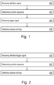
- Fig. 1 illustrates a method for controlling an RF receiver antenna assembly by a controlling unit.
- the RF receiver antenna may comprise an RF receiver coil for magnetic resonance imaging, a detuning assembly configured for operating the receiver coil in a tuned operational mode and a detuned operational mode, and the controlling unit.
- the detuning assembly comprises a switch configured for switching between the tuned operational mode and the detuned operational mode.
- the controlling unit is configured for controlling the switch in response to a wireless RF trigger signal being received via the receiver coil.
- the controlling unit receives a wireless RF definition signal via the receiver coil defining an MRI sequence.
- the wireless RF definition signal may, e.g., comprise the MRI sequence.
- the wireless RF definition signal may, e.g., comprise features of the MRI sequence.
- the controlling unit determines in block 202 a control sequence for controlling the switch using the received wireless RF definition signal.
- the control sequence controls the switch to operate the receiver coil in the detuned operational mode during a transmission of the pulses of the MRI sequence and in the tuned operational mode during the rest of the MRI sequence.
- Determining the control sequence may comprise determining a temporal pattern of pulses of the MRI sequence using the wireless RF definition signal. The determined temporal pattern of pulses may be used for the determining of the control sequence.
- the controlling unit receives the wireless RF trigger signal via the receiver coil.
- the controlling unit switches in block 208 the receiver coil between the tuned operational mode and the detuned operational mode according to the control sequence using the switch.
- the RF trigger signal may, e.g., comprise the MRI sequence.
- the RF trigger signal may, e.g., be a dedicated signal indicating a start of an MRI RF pulse signal.
- the RF trigger signal may be a switching of a carrier sequence.
- the RF trigger signal may comprise a trigger encoded in the wireless RF trigger signal.
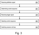
- Fig. 3 illustrates another method for controlling an RF receiver antenna assembly as described in view of Fig. 1 by the controlling unit.
- the controlling unit receives a wireless RF definition signal via the receiver coil defining an MRI sequence.
- the controlling unit determines in block 202 a control sequence for controlling the switch using the received wireless RF definition signal.
- the control sequence controls the switch to operate the receiver coil in the detuned operational mode during a transmission of the pulses of the MRI sequence and in the tuned operational mode during the rest of the MRI sequence.
Landscapes
- Physics & Mathematics (AREA)
- Condensed Matter Physics & Semiconductors (AREA)
- General Physics & Mathematics (AREA)
- Engineering & Computer Science (AREA)
- Computer Networks & Wireless Communication (AREA)
- Magnetic Resonance Imaging Apparatus (AREA)
Priority Applications (2)
| Application Number | Priority Date | Filing Date | Title |
|---|---|---|---|
| EP23200724.5A EP4530652A1 (de) | 2023-09-29 | 2023-09-29 | Antennenanordnung für hochfrequenzempfänger |
| PCT/EP2024/076656 WO2025068110A1 (en) | 2023-09-29 | 2024-09-23 | Radio frequency receiver antenna assembly |
Applications Claiming Priority (1)
| Application Number | Priority Date | Filing Date | Title |
|---|---|---|---|
| EP23200724.5A EP4530652A1 (de) | 2023-09-29 | 2023-09-29 | Antennenanordnung für hochfrequenzempfänger |
Publications (1)
| Publication Number | Publication Date |
|---|---|
| EP4530652A1 true EP4530652A1 (de) | 2025-04-02 |
Family
ID=88237693
Family Applications (1)
| Application Number | Title | Priority Date | Filing Date |
|---|---|---|---|
| EP23200724.5A Pending EP4530652A1 (de) | 2023-09-29 | 2023-09-29 | Antennenanordnung für hochfrequenzempfänger |
Country Status (2)
| Country | Link |
|---|---|
| EP (1) | EP4530652A1 (de) |
| WO (1) | WO2025068110A1 (de) |
Citations (2)
| Publication number | Priority date | Publication date | Assignee | Title |
|---|---|---|---|---|
| US20190265317A1 (en) * | 2016-09-29 | 2019-08-29 | Koninklijke Philips N.V. | Wireless magnetic resonance energy harvesting and coil detuning |
| US10416252B2 (en) * | 2014-07-01 | 2019-09-17 | Koninklijke Philips N.V. | MR receive coil with detune circuit and energy harvesting circuit |
-
2023
- 2023-09-29 EP EP23200724.5A patent/EP4530652A1/de active Pending
-
2024
- 2024-09-23 WO PCT/EP2024/076656 patent/WO2025068110A1/en active Pending
Patent Citations (2)
| Publication number | Priority date | Publication date | Assignee | Title |
|---|---|---|---|---|
| US10416252B2 (en) * | 2014-07-01 | 2019-09-17 | Koninklijke Philips N.V. | MR receive coil with detune circuit and energy harvesting circuit |
| US20190265317A1 (en) * | 2016-09-29 | 2019-08-29 | Koninklijke Philips N.V. | Wireless magnetic resonance energy harvesting and coil detuning |
Non-Patent Citations (3)
| Title |
|---|
| JONATHAN CUTHBERTSON ET AL: "An Integrated Radio-Frequency/Wireless (iRFW) Coil Design for Wireless Q-Spoiling During MR Imaging", PROCEEDINGS OF THE 2021 ISMRM & SMRT ANNUAL MEETING & EXHIBITION, 15-20 MAY 2021, ISMRM, 2030 ADDISON STREET, 7TH FLOOR, BERKELEY, CA 94704 USA, no. 1605, 30 April 2021 (2021-04-30), XP040723624 * |
| NOHAVA LENA ET AL: "Perspectives in Wireless Radio Frequency Coil Development for Magnetic Resonance Imaging", FRONTIERS IN PHYSICS, vol. 8, 21 February 2020 (2020-02-21), XP093140316, ISSN: 2296-424X, DOI: 10.3389/fphy.2020.00011 * |
| YU J. Y. ET AL.: "Wireless Q-spoiling of Receive Coils at 1.5T MRI", PROCEEDINGS OF THE INTERNATIONAL SOCIETY FOR MAGNETIC RESONANCE IN MEDICINE, ISMRM, 25TH ANNUAL MEETING & EXHIBITION 2017, no. 4297, 7 April 2017 (2017-04-07), USA, XP040691865 * |
Also Published As
| Publication number | Publication date |
|---|---|
| WO2025068110A1 (en) | 2025-04-03 |
Similar Documents
| Publication | Publication Date | Title |
|---|---|---|
| CN104603630B (zh) | 具有基于导航器的运动检测的磁共振成像系统 | |
| EP3486674A1 (de) | Lokalisierung anatomischer landmarken durch künstliche intelligenz | |
| EP3477583A1 (de) | Auf deep-learning basierte verarbeitung von bewegungsartefakten in magnetresonanz-bildgebungsdaten | |
| CN107003258B (zh) | 空间分辨的金属探测器 | |
| CN102327117B (zh) | 用于建立磁共振图像的方法和相应构造的磁共振设备 | |
| US20210156940A1 (en) | Automatic artifact detection and pulse sequence modification in magnetic resonance imaging | |
| US10698064B2 (en) | Motion-corrected compressed sensing magnetic resonance imaging | |
| CN109844555A (zh) | 无线磁共振能量收集和线圈去谐 | |
| CN112262321B (zh) | 用于配置rf发射组件的方法 | |
| EP4530652A1 (de) | Antennenanordnung für hochfrequenzempfänger | |
| CN113805114A (zh) | 预测在磁共振装置中使用的模块的可能的故障 | |
| US12078703B2 (en) | Automated field of view alignment for magnetic resonance imaging | |
| EP3521849A1 (de) | Mrt mit fett-/wassertrennung | |
| EP3564962A1 (de) | Bewegungsartefaktvorhersage bei der datenerfassung | |
| CN114175111A (zh) | 利用机器学习的fMRI任务设置 | |
| US20220165004A1 (en) | Removal of false positives from white matter fiber tracts | |
| JP7459114B2 (ja) | 受信コイル位置の自動検出 | |
| EP4138092A1 (de) | Erkennung von falsch konfigurierten medizinischen bildgebungssystemen | |
| EP4636429A1 (de) | Kompensation von elektromagnetischen störsignalen in der magnetresonanzbildgebung | |
| EP4481422A1 (de) | Überwachungsvorrichtung für ein magnetresonanzbildgebungssystem | |
| EP3524996A1 (de) | Reduzierung von artefakten bei paralleler magnetischer resonanzbildgebung | |
| EP4306983A1 (de) | Durchführung anatomischer messungen mittels kernspinresonanz bildgebung | |
| EP4386414A1 (de) | Kernmagnetische resonanzspektroskopie zur detektion eines vorbestimmten gewebetyps | |
| EP4498107A1 (de) | Medizinisches system mit einer flexible magnetresonanz-bildgebungsspule mit einem biegesensor, einem verfahren zum betreiben des medizinischen systems und einem computerprogramm, welches das medizinische system steuert | |
| CN112394310B (zh) | 梯度系统及其操控方法、成像系统、程序产品和数据载体 |
Legal Events
| Date | Code | Title | Description |
|---|---|---|---|
| PUAI | Public reference made under article 153(3) epc to a published international application that has entered the european phase |
Free format text: ORIGINAL CODE: 0009012 |
|
| STAA | Information on the status of an ep patent application or granted ep patent |
Free format text: STATUS: THE APPLICATION HAS BEEN PUBLISHED |
|
| AK | Designated contracting states |
Kind code of ref document: A1 Designated state(s): AL AT BE BG CH CY CZ DE DK EE ES FI FR GB GR HR HU IE IS IT LI LT LU LV MC ME MK MT NL NO PL PT RO RS SE SI SK SM TR |