EP4530649A1 - Vorrichtung und verfahren zum testen von schutzschaltungen in hochspannungs-/schaltgeräten - Google Patents
Vorrichtung und verfahren zum testen von schutzschaltungen in hochspannungs-/schaltgeräten Download PDFInfo
- Publication number
- EP4530649A1 EP4530649A1 EP23199754.5A EP23199754A EP4530649A1 EP 4530649 A1 EP4530649 A1 EP 4530649A1 EP 23199754 A EP23199754 A EP 23199754A EP 4530649 A1 EP4530649 A1 EP 4530649A1
- Authority
- EP
- European Patent Office
- Prior art keywords
- coil
- test
- conductors
- voltage
- rogowski coil
- Prior art date
- Legal status (The legal status is an assumption and is not a legal conclusion. Google has not performed a legal analysis and makes no representation as to the accuracy of the status listed.)
- Pending
Links
Images





Classifications
-
- G—PHYSICS
- G01—MEASURING; TESTING
- G01R—MEASURING ELECTRIC VARIABLES; MEASURING MAGNETIC VARIABLES
- G01R35/00—Testing or calibrating of apparatus covered by the other groups of this subclass
-
- G—PHYSICS
- G01—MEASURING; TESTING
- G01R—MEASURING ELECTRIC VARIABLES; MEASURING MAGNETIC VARIABLES
- G01R31/00—Arrangements for testing electric properties; Arrangements for locating electric faults; Arrangements for electrical testing characterised by what is being tested not provided for elsewhere
- G01R31/327—Testing of circuit interrupters, switches or circuit-breakers
- G01R31/3277—Testing of circuit interrupters, switches or circuit-breakers of low voltage devices, e.g. domestic or industrial devices, such as motor protections, relays, rotation switches
-
- G—PHYSICS
- G01—MEASURING; TESTING
- G01R—MEASURING ELECTRIC VARIABLES; MEASURING MAGNETIC VARIABLES
- G01R15/00—Details of measuring arrangements of the types provided for in groups G01R17/00 - G01R29/00, G01R33/00 - G01R33/26 or G01R35/00
- G01R15/14—Adaptations providing voltage or current isolation, e.g. for high-voltage or high-current networks
- G01R15/18—Adaptations providing voltage or current isolation, e.g. for high-voltage or high-current networks using inductive devices, e.g. transformers
- G01R15/181—Adaptations providing voltage or current isolation, e.g. for high-voltage or high-current networks using inductive devices, e.g. transformers using coils without a magnetic core, e.g. Rogowski coils
-
- G—PHYSICS
- G01—MEASURING; TESTING
- G01R—MEASURING ELECTRIC VARIABLES; MEASURING MAGNETIC VARIABLES
- G01R31/00—Arrangements for testing electric properties; Arrangements for locating electric faults; Arrangements for electrical testing characterised by what is being tested not provided for elsewhere
- G01R31/327—Testing of circuit interrupters, switches or circuit-breakers
- G01R31/3271—Testing of circuit interrupters, switches or circuit-breakers of high voltage or medium voltage devices
- G01R31/3272—Apparatus, systems or circuits therefor
-
- G—PHYSICS
- G01—MEASURING; TESTING
- G01R—MEASURING ELECTRIC VARIABLES; MEASURING MAGNETIC VARIABLES
- G01R31/00—Arrangements for testing electric properties; Arrangements for locating electric faults; Arrangements for electrical testing characterised by what is being tested not provided for elsewhere
- G01R31/327—Testing of circuit interrupters, switches or circuit-breakers
- G01R31/3271—Testing of circuit interrupters, switches or circuit-breakers of high voltage or medium voltage devices
- G01R31/3272—Apparatus, systems or circuits therefor
- G01R31/3274—Details related to measuring, e.g. sensing, displaying or computing; Measuring of variables related to the contact pieces, e.g. wear, position or resistance
-
- G—PHYSICS
- G01—MEASURING; TESTING
- G01R—MEASURING ELECTRIC VARIABLES; MEASURING MAGNETIC VARIABLES
- G01R31/00—Arrangements for testing electric properties; Arrangements for locating electric faults; Arrangements for electrical testing characterised by what is being tested not provided for elsewhere
- G01R31/327—Testing of circuit interrupters, switches or circuit-breakers
- G01R31/3271—Testing of circuit interrupters, switches or circuit-breakers of high voltage or medium voltage devices
- G01R31/3275—Fault detection or status indication
-
- H—ELECTRICITY
- H02—GENERATION; CONVERSION OR DISTRIBUTION OF ELECTRIC POWER
- H02H—EMERGENCY PROTECTIVE CIRCUIT ARRANGEMENTS
- H02H3/00—Emergency protective circuit arrangements for automatic disconnection directly responsive to an undesired change from normal electric working condition with or without subsequent reconnection ; integrated protection
- H02H3/08—Emergency protective circuit arrangements for automatic disconnection directly responsive to an undesired change from normal electric working condition with or without subsequent reconnection ; integrated protection responsive to excess current
-
- G—PHYSICS
- G01—MEASURING; TESTING
- G01R—MEASURING ELECTRIC VARIABLES; MEASURING MAGNETIC VARIABLES
- G01R31/00—Arrangements for testing electric properties; Arrangements for locating electric faults; Arrangements for electrical testing characterised by what is being tested not provided for elsewhere
- G01R31/50—Testing of electric apparatus, lines, cables or components for short-circuits, continuity, leakage current or incorrect line connections
- G01R31/54—Testing for continuity
Definitions
- GIS Gas Insulated Switchgears
- FIG. 1A shows a Rogowski coil 4 according to US5414400 , comprising a plate 11 of a printed circuit, for example made of epoxy resin; the coil comprises deposits of copper 3 on each face of the plate, the deposits of one face being connected to the deposits of the other face via plated through holes 5 passing through the plate.
- the coil has terminals 7, 9.
- a Rogowski coil 4 is usually connected to a protection circuit 8 which can open switches or circuit breakers 15 in case of any default, for example a surge of current in the GIS or a short circuit 17.
- a protection circuit 8 which can open switches or circuit breakers 15 in case of any default, for example a surge of current in the GIS or a short circuit 17.
- Such default can generate currents as high as several tens of A or event higher than 100 000 A, which are very dangerous both for operators and for the whole system and can result in interruptions of several months. It is necessary to test whether the protection circuit and the switches or circuit breakers 15 operate properly. But it is of course impossible to simulate a real default 17 because of the very high currents (up to 100 000 A) which are required: a portable generator can generate at most several tens or hundreds of A.
- test circuits have been developed to test the protection circuits 8, 15.
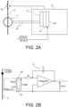
- a conventional test of the protection circuit is schematically illustrated on figure 2A , on which reference 2 designates a conductor around which a Rogowski coil 4 is arranged in order to measure a current circulating therein, the coil 4 generating a secondary voltage signal which is supplied to a system 8 comprising an integrator 6, a compensation stage 61 and a digitalization stage 63 in order to test the protection devices 15 against, for example, overcurrents.
- the magnetic field created by the primary current which usually circulates in conductor 2 generates a voltage at the terminals 7, 9 of the coil.
- This voltage is for example approximately of the order of 50 mV/kA at 50Hz.
- this voltage v rogo is integrated by integrator 6; the resulting voltage V out is representative of the primary current circulating in conductor 2 and can be digitized and processed.
- the coil is represented by an equivalent circuit comprising an inductance 41 and a resistance 42 in series.
- a test current is directly injected into the protection system 8, in particular directly to the digitalization stage 63, in order to test the protection functions and devices 15.
- the components located upstream of the digitalization stage, in particular the wires 13 and the integrator 6 and the coil 4 itself are not tested.
- the current which is injected as a test current is not representative of the secondary voltage signal output by the coil 4; in other words, the test is performed under conditions which are not representing the actual signal generated by the coil 4 when it is measuring a current in the conductor 2.
- test signals which are representative of the actual signals generated by the coil 4 when it is measuring a current in the conductor 2 and when a default (like default 17 on figure 1B ) appears
- the present invention first concerns a test device, to test for example a Rogowski coil and an associated protection device connected to said coil via conductors, comprising:
- a test device to test a Rogowski coil and an associated protection device connected to said coil via conductors comprises:
- the voltage which is output by device according to the invention is representative of the output signal of a Rogowski coil.
- Said transformation means can comprise a capacitive circuit, comprising for example at least 1 capacitor, for example 2 capacitors.
- a resistor can be arranged in parallel to said at least one capacitor.
- said at least one resistor has an impedance much smaller than the impedance of said coil and said at least one capacitor.
- said means to generate a test voltage can comprise an alternative current generator.
- said alternative current generator comprises a controller and preferably at least one memory storing or to store data of at least one, preferably several, waveform(s) which can be used for testing.
- said transformation means can comprise one or more electrical components, for example at least one resistor and/or at least one capacitor, and can further comprise means to vary at least one electrical characteristic at least one of said electronic components.
- Said at least one electrical characteristic of at least one of said electronic components can be varied on the basis of one or more tests performed on a Rogowski coil tested with a device according to the invention.
- said transformation means can comprise terminals to provide said means to process with a signal from a Rogowski coil under test.
- the invention also concerns a Rogowski coil and an associated protection system connected to said coil via conductors, said conductors comprising connectors to connect a test device according to the invention.
- Said Rogowski coil can further comprise a memory storing one more characteristic, for example the sensitivity and/or the resistance and/or the inductance, of said coil.
- One or more conductors can connect said memory to at least one part, for example a compensation stage, of said protection system.
- Said protection system can comprise one or more switch(es) and/or one or more circuit breaker(s), the test device comprising means to detect whether at least one switch or at least one circuit breaker opens when a default is detected.
- the invention applies to a single-phase conductor or to one or more phase(s) of a system having several, for example 3, phases.
- the invention also concerns a single phase or a 3 phase GIS, comprising at least one conductor, at least one Rogowski coil around said at least one conductor and at least one test device according to the invention.
- the invention also concerns a method to test a Rogowski coil according to the invention, said coil being arranged around a main conductor, said method comprising:
- a protection system connected to a Rogowski coil can comprise one or more of :
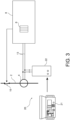
- FIG. 3 An embodiment of the present invention is shown on figure 3 .
- Rogowski coil 4 for example as disclosed above in connection with figure 1A , said coil 4 being arranged around a conductor 2 in order to measure a current circulating in said conductor.
- the coil 4 generates a secondary voltage signal which is supplied to an integrator 6 forming part of protection system 8 which controls one or more protection device(s), for example one or more switch(es) and/or circuit breaker(s) 15, in case, for example, of overcurrents.
- a test device 20 is connected to the conductors 13, between the coil 4 and the integrator 6, in order to inject in said conductors a current representative of a signal at the terminals of coil 4 when it is measuring a current circulating in conductor 2.
- a test current of some A or some tens of A results in a current at the outlet of the test device 20 very comparable to the current generated by the coil when a primary current of several tens of kA circulates in conductor 2.
- Test device 20 comprises for example a current generator or source 21 able to generate a current of for example between 0 and 100 A and an interface tool or device 22.
- a voltage source could be used instead of the current source and of the impedance 220 (see below) but it is preferable to use a current source in order to simulate a primary current.
- Figure 4 shows a more detailed representation of an embodiment of test device 20.
- the generator 21 comprises an electronic circuit 210 which controls an AC source 213 to generate a 1 st alternating voltage between its outlet terminals 211, 212. Said terminals can be connected to inlet terminals 221, 222 of the interface device 22. Thus generator 21 is able to supply a voltage (1 st alternating voltage) to the interface device 22. This 1 st alternating voltage applied to a resistor 220 and capacitors 223, 224 of the interface device is able to generate a test voltage V test representative of the voltage at the terminals of the coil 4.
- the generator 21 can further comprise one or more memory/ies 214 to store waveform data in order to simulate one or more default(s), for example over-currents or over intensities or over-voltage on one or more phases, to test the elements or components downstream of coil 4, including the protection device 8.
- one or more memory/ies 214 to store waveform data in order to simulate one or more default(s), for example over-currents or over intensities or over-voltage on one or more phases, to test the elements or components downstream of coil 4, including the protection device 8.
- An over-current is a current, respectively a voltage, that the machine cannot accept except during a very short time: the machine has a rated current, of for example 3000 A eff, which it can permanently accept, but it can accept an overcurrent higher than the rated current, for example at least 2 times the rated current, only for a short period of time, for example for some 10 ms and some s, or between 50 ms and 5s; beyond the end of that period of time, the machine must be stopped or the current interrupted.
- a rated current of for example 3000 A eff, which it can permanently accept, but it can accept an overcurrent higher than the rated current, for example at least 2 times the rated current, only for a short period of time, for example for some 10 ms and some s, or between 50 ms and 5s; beyond the end of that period of time, the machine must be stopped or the current interrupted.
- An operator and/or a a computer or a controller can select one or more of these data files and the electronic circuit 210 can provide the system (interface device 22) with the corresponding signal comprising or simulating said one or more simulated default(s).
- Interface device 22 comprises a resistor 220 and inlet terminals 221, 222 to supply said resistor 220 with the outlet voltage provided by generator 21.
- Resistor 220 has a value such that the alternating current i 1 circulating therein is representative of the primary current usually circulating in conductor 2, for example between 50 and 100 kA
- resistor 220 can be adapted depending on the test performed.
- the terminals of the resistor can be connected, for example through one or more capacitor(s) 223, 224, to outlet terminals 231, 232 of interface device 22.
- Said one or more capacitor(s) 223, 224 are test capacitors.
- this/these capacitor(s) will block any direct current or direct voltage component so that it is not supplied to the system comprising the conductors 13 and the protection device 8.
- the value of these capacitor(s) can be adapted depending on the test performed.
- the voltage between outlet terminals 231, 232 is representative of, or very comparable to, the secondary voltage at the outlet of coil 4; for example it is comprised between 0.5 V and 10V.
- Interface device 22 can furthermore comprise a microcontroller 226 and a display device 228 as explained below.
- Outlet terminals 231, 232 of interface device 22 can be connected to the conductors 13 (upstream of the protection system 8) via test plugs or connectors 131, 132 of said conductors.
- the system 20 can provide the conductors 13 with a test signal (a voltage) which is very similar to the secondary voltage generated by the coil 4 detecting a primary current in conductor 2.
- test signals allow testing the conductors 13 and all other components between (and including) the coil 4 and the system 8, which comprises the integrator 6 but also a compensation stage 61 (this stage being fed with information from a memory, for example an EEPROM 80, about the sensitivity and/or the resistance and/or the inductance of the coil 4) and/or one or more filter(s) and/or one or more protection device(s) 15 (for example one or more switch(es) and/or circuit breaker(s)) to protect against defaults such as over currents or over intensities, and/or faults to ground etc.
- a memory for example an EEPROM 80
- the test device 20 injects into the conductors 13 a signal comprising one or more default(s), but the protection device does not trigger the switches or circuit-breakers 15 and/or does not interrupt the current circulating in conductor 2, then it is decided that the protection system does not work properly and should be checked and possibly repaired.
- the simulated default is seen by the system and it is possible to check whether a signal is generated to open the switch(es) and/or the circuit breaker(s) 15. If the protection device triggers the switches or circuit-breakers 15 or interrupts the current circulating in conductor 2, then it is decided that the protection system works properly.
- a signal representing the current inside the system 8 can be derived through conductors 93 which can for example be connected to test plugs 831, 832 of conductors 83 connecting the memory 80 to the compensation stage 61.
- This signal can be supplied to inlet terminals 241, 243 of the interface device 22 and then, for example, to microcontroller 226 and to display device 228.
- Figure 8 is an example of a test voltage (curve I) generated by a test device according to the invention, curve II (90° out of phase with respect to curve I) being the voltage measured or detected between the plugs 831, 832.
- the microcontroller 226 can be programmed or adapted to regulate the parameters of the electrical components of the interface device 22, for example resistor 220 and/or capacitor(s) 223, 225, depending on the signal received from the system 8.
- One or more data of memory 80 in particular one or more of the above-mentioned data about the coil 4, can also be provided to microcontroller 226.
- Rogowski coils can have different properties from each other, in particular different sensitivities; the information about these properties, for example the sensitivity, can therefore be read from said memory 80 and can be used when regulating the electrical components of the interface device 22.
- Figure 5 shows an equivalent diagram of the circuit disclosed above in connection with figure 4 together with the integration stage 6 (which forms part of the protection system 8).
- the references designate the same elements or components as above.
- Reference 213' is a current source connected to the terminals of the resistor 220.
- the Rogowski coil 4 is represented by resistor 42 and capacitor 41.
- the secondary signal generated by the coil 4 is integrated by the integrator 6
- any current circulating in the primary circuit (in the conductor 2) is interrupted.
- the Rogowski coil therefore does not generate any secondary voltage and is ready for a test.
- the system 8 and the conductors 13 remain connected to coil 4.
- the interface device 22 is connected to generator 21 and to conductors 13 as shown on figure 4 .
- the test circuit is therefore connected in parallel to the Rogowski coil 4.
- the current source 213' generates a test current I T which is representative of the default current, for example of a short-circuit current.
- test current primarily circulates through resistor 220 (which has an impedance R 220 which is small with respect to the impedance of the other branch of the circuit (capacitors 222, 223 and coil 4); for example: 10 ⁇ R 220 ⁇ Z CT1 + Z 4 + Z CT2 .
- V test simulates the behaviour of Rogowski coil 4 in reaction to a primary current and depends on the respective values of the capacitors 223, 224, of resistor 42 and of inductance 41.
- the values of capacitors 223, 224 and of resistor 42 are selected so that V test is comparable to the voltage at the terminals of coil 4 when it is subject to primary current I T .
- the one or more capacitors CT1, CT2 behave like coupling capacitors allowing a derived or a test alternative current to circulate in the Rogowski coil which is in an idle state (no primary current is circulating in conductor 2).
- the voltage generated at the terminals of the Rogowski coil mirrors the behaviour of the coil as if it was detecting a current in conductor 2.
- the Rogowski coil When a current (primary signal) circulates in conductor 2, the Rogowski coil generates a secondary signal, wherein the resistance of the coil does not play any significant role.
- a test performed according to the present invention makes use of the resistance of the Rogowski coil (by circulating a current therein) to generate the secondary voltage, independently from the Rogowski effect.
- Example values which can be used for a test device according to the invention are as follows:
- test device offers the following advantages.
- the main circuit (including coil 4, conductors 13 and system 8) is protected from common mode signals through the capacitors 223, 224.
- a default of the Rogowski coil (for example a cut or a short-circuit of wire 3) can be detected since it will affect V test .
- the whole chain from and including the Rogowski coil 4 to the complete protection system 8, including any filtering and/or integrating stage, can be tested, which is not the case with usual digital signals directly sent to the protection system 8 (as on figure 2A ).
- a test circuit according to the invention allows injecting currents of the order of some Amp into the protection circuit 8 and the coil 4, which are representative of a primary current (in conductor 2) of several tens or hundreds of kA.
- the primary circuit circulating in the conductor 2 is interrupted and the Rogowski coil 4 therefore does not generate any voltage.
- a test implementing the invention can be performed.
- the invention was disclosed in connection with one conductor 2 or one phase.
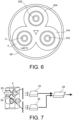
- Figure 6 represents an enclosure 60 containing 3 conductors 2, 102, 202, for example conductors of a 3-phases system, a Rogowski coil 4, 104, 204 being arranged around each of said conductors.
- Each of these coils can be tested with a test device or a test method according to the invention.
- the same test device 20 can successively be connected to the conductors 13 associated with each of the 3 Rogowski coils.
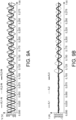
- the signal from each test can be provided to a control unit, for example a computer or a controller or a microprocessor (not illustrated on the figures), to sample and/or process said signal; it can generate a test signal as shown on figure 9A , including some default(s).
- Device 21 or 210 ( figures 3 , 4 ) can be programmed so that an alarm is triggered when the simulated current increases above a threshold 300, here at about 5A.
- Figure 7 represents a Rogowski coil 4 implemented around a conductor 2.
- the signals from the coil can be sent to a converter 32 to convert said signal into optical signals.
- Other signals from one or more other sensor(s), for example a capacitive sensor 34, can also be converted by a converter 36 into optical signals.
- the optical signals can be merged in a merging unit 28.
- the merging unit can comprise a microprocessor to process data and can have calculation capabilities.
- Rogowski coil 4 can be tested according to the teaching of the present invention. The same system may be implemented for several coils, like for example on figure 6 .
- a test device 20 according to the invention can be easily disconnected from and connected to test plugs 131, 132 of the conductors 13 connected to the terminals of a Rogowski coil 4.
- a test according to the invention therefore does not need to implement or to activate any switching element which could create disturbances. Indeed, currents circulating on the secondary side of a Rogowski coil are rather weak: if the conductors had to be interrupted to make a test, other test, namely continuity tests, should be performed to reconnect the conductors (the contact impedance of the connections could result in a fainting of the signal).
- test device 20 offers flexibility because the interface device 22 can be:
Landscapes
- Physics & Mathematics (AREA)
- General Physics & Mathematics (AREA)
- Engineering & Computer Science (AREA)
- Power Engineering (AREA)
- Theoretical Computer Science (AREA)
- Measuring Instrument Details And Bridges, And Automatic Balancing Devices (AREA)
- Measurement Of Current Or Voltage (AREA)
- Testing Electric Properties And Detecting Electric Faults (AREA)
- Emergency Protection Circuit Devices (AREA)
Priority Applications (6)
| Application Number | Priority Date | Filing Date | Title |
|---|---|---|---|
| EP23199754.5A EP4530649A1 (de) | 2023-09-26 | 2023-09-26 | Vorrichtung und verfahren zum testen von schutzschaltungen in hochspannungs-/schaltgeräten |
| US18/895,802 US20250102576A1 (en) | 2023-09-26 | 2024-09-25 | Device and method for testing protection circuits in high-voltage/switchgear |
| JP2024165758A JP2025056773A (ja) | 2023-09-26 | 2024-09-25 | 高電圧/開閉器の保護回路をテストする装置と方法 |
| KR1020240130038A KR20250046206A (ko) | 2023-09-26 | 2024-09-25 | 고전압/스위치기어에서 보호 회로를 테스트하는 디바이스 및 방법 |
| CA3255220A CA3255220A1 (en) | 2023-09-26 | 2024-09-26 | Device and method for testing protection circuits in high- voltage/switchgear |
| CN202411348330.XA CN119716200A (zh) | 2023-09-26 | 2024-09-26 | 用于测试高压/开关设备中的保护电路的装置和方法 |
Applications Claiming Priority (1)
| Application Number | Priority Date | Filing Date | Title |
|---|---|---|---|
| EP23199754.5A EP4530649A1 (de) | 2023-09-26 | 2023-09-26 | Vorrichtung und verfahren zum testen von schutzschaltungen in hochspannungs-/schaltgeräten |
Publications (1)
| Publication Number | Publication Date |
|---|---|
| EP4530649A1 true EP4530649A1 (de) | 2025-04-02 |
Family
ID=88204304
Family Applications (1)
| Application Number | Title | Priority Date | Filing Date |
|---|---|---|---|
| EP23199754.5A Pending EP4530649A1 (de) | 2023-09-26 | 2023-09-26 | Vorrichtung und verfahren zum testen von schutzschaltungen in hochspannungs-/schaltgeräten |
Country Status (6)
| Country | Link |
|---|---|
| US (1) | US20250102576A1 (de) |
| EP (1) | EP4530649A1 (de) |
| JP (1) | JP2025056773A (de) |
| KR (1) | KR20250046206A (de) |
| CN (1) | CN119716200A (de) |
| CA (1) | CA3255220A1 (de) |
Families Citing this family (1)
| Publication number | Priority date | Publication date | Assignee | Title |
|---|---|---|---|---|
| SE2350615A1 (en) * | 2023-05-23 | 2024-10-22 | Megger Sweden Ab | Method and device for testing protection relays |
Citations (5)
| Publication number | Priority date | Publication date | Assignee | Title |
|---|---|---|---|---|
| US5414400A (en) | 1992-06-05 | 1995-05-09 | Gec Alsthom T&D Sa | Rogowski coil |
| US20130057307A1 (en) * | 2011-09-06 | 2013-03-07 | Siemens Aktiengesellschaft | Circuit breaker and method for checking a rogowski converter in a circuit breaker |
| US20170322258A1 (en) * | 2014-11-10 | 2017-11-09 | Eaton Corporation | Circuit interrupter and system for testing the same |
| CN110412326A (zh) * | 2018-04-27 | 2019-11-05 | 施耐德电器工业公司 | 可测试电流变换器和包括用于测试其的装置的电气设备 |
| US20210088556A1 (en) * | 2019-09-23 | 2021-03-25 | Eaton Intelligent Power Limited | Circuit interrupter and method of estimating a temperature of a busbar in a circuit interrupter |
-
2023
- 2023-09-26 EP EP23199754.5A patent/EP4530649A1/de active Pending
-
2024
- 2024-09-25 JP JP2024165758A patent/JP2025056773A/ja active Pending
- 2024-09-25 US US18/895,802 patent/US20250102576A1/en active Pending
- 2024-09-25 KR KR1020240130038A patent/KR20250046206A/ko active Pending
- 2024-09-26 CN CN202411348330.XA patent/CN119716200A/zh active Pending
- 2024-09-26 CA CA3255220A patent/CA3255220A1/en active Pending
Patent Citations (5)
| Publication number | Priority date | Publication date | Assignee | Title |
|---|---|---|---|---|
| US5414400A (en) | 1992-06-05 | 1995-05-09 | Gec Alsthom T&D Sa | Rogowski coil |
| US20130057307A1 (en) * | 2011-09-06 | 2013-03-07 | Siemens Aktiengesellschaft | Circuit breaker and method for checking a rogowski converter in a circuit breaker |
| US20170322258A1 (en) * | 2014-11-10 | 2017-11-09 | Eaton Corporation | Circuit interrupter and system for testing the same |
| CN110412326A (zh) * | 2018-04-27 | 2019-11-05 | 施耐德电器工业公司 | 可测试电流变换器和包括用于测试其的装置的电气设备 |
| US20210088556A1 (en) * | 2019-09-23 | 2021-03-25 | Eaton Intelligent Power Limited | Circuit interrupter and method of estimating a temperature of a busbar in a circuit interrupter |
Also Published As
| Publication number | Publication date |
|---|---|
| CA3255220A1 (en) | 2026-01-19 |
| KR20250046206A (ko) | 2025-04-02 |
| CN119716200A (zh) | 2025-03-28 |
| JP2025056773A (ja) | 2025-04-08 |
| US20250102576A1 (en) | 2025-03-27 |
Similar Documents
| Publication | Publication Date | Title |
|---|---|---|
| CN107966633B (zh) | 一种供电系统的配电网单相接地故障线路快速判断方法及系统 | |
| US6396279B1 (en) | Method and device for testing differential protection relays or differential protection relay systems | |
| EP1385015B1 (de) | Prüfvorrichtung für mehrere Leistungsschalter mit einem Bereich von möglichen Nennströmen und mit mehreren Auslösefunktionen | |
| US6218844B1 (en) | Method and apparatus for testing an arcing fault circuit interrupter | |
| Espinoza et al. | Faulted phase selection for half-wavelength power transmission lines | |
| JP2004170093A (ja) | 電気設備保護回路の試験装置及び試験方法 | |
| US20250102576A1 (en) | Device and method for testing protection circuits in high-voltage/switchgear | |
| US4634981A (en) | Method for testing a circuit breaker using a three terminal current transformer | |
| US6765390B2 (en) | Diagnostic wiring verification tester | |
| Kokor et al. | Effects of neutral point grounding methods on single-phase short circuit fault characteristics | |
| JP2008263762A (ja) | 地絡保護継電器システム | |
| Steurer et al. | Calculating the transient recovery voltage associated with clearing transformer determined faults by means of frequency response analysis | |
| Hamouda et al. | Practical Evaluation of Overcurrent Protective Relay Performance in Power Distribution System | |
| JP2008263761A (ja) | 配電線人工地絡試験装置および配電線人工地絡試験方法 | |
| Albrechtowicz et al. | The analysis of the effectiveness of standard protection devices in supply systems fed from synchronous generator sets | |
| KR100637619B1 (ko) | 병렬 커패시터 뱅크의 전압 차동 보호 방법 및 장치 | |
| Dumitru et al. | Numeric simulation of faults in electrical networks | |
| Patwardhan et al. | Faults unveiled: An in-depth MATLAB simulation study of transmission line anomalies | |
| CN107132463A (zh) | 电压互感器二次绕组防短路装置 | |
| JP2607623B2 (ja) | 軽地絡発生ケーブルの判別方法 | |
| SU1663581A1 (ru) | Устройство дл испытани трансформаторов в режиме короткого замыкани | |
| Nimmersjo et al. | Protective relay testing using a modern digital real time simulator | |
| CN222979718U (zh) | 调试终端、调试系统以及中压柜 | |
| JPH0735831A (ja) | 遮断器の試験方法及びその装置 | |
| CN218783576U (zh) | 电弧故障保护装置 |
Legal Events
| Date | Code | Title | Description |
|---|---|---|---|
| PUAI | Public reference made under article 153(3) epc to a published international application that has entered the european phase |
Free format text: ORIGINAL CODE: 0009012 |
|
| STAA | Information on the status of an ep patent application or granted ep patent |
Free format text: STATUS: THE APPLICATION HAS BEEN PUBLISHED |
|
| AK | Designated contracting states |
Kind code of ref document: A1 Designated state(s): AL AT BE BG CH CY CZ DE DK EE ES FI FR GB GR HR HU IE IS IT LI LT LU LV MC ME MK MT NL NO PL PT RO RS SE SI SK SM TR |
|
| STAA | Information on the status of an ep patent application or granted ep patent |
Free format text: STATUS: REQUEST FOR EXAMINATION WAS MADE |
|
| 17P | Request for examination filed |
Effective date: 20250721 |
|
| RAP3 | Party data changed (applicant data changed or rights of an application transferred) |
Owner name: GE VERNOVA TECHNOLOGY GMBH |