EP4530578A1 - Taxiassistent mit erweiterter realität - Google Patents
Taxiassistent mit erweiterter realität Download PDFInfo
- Publication number
- EP4530578A1 EP4530578A1 EP24198124.0A EP24198124A EP4530578A1 EP 4530578 A1 EP4530578 A1 EP 4530578A1 EP 24198124 A EP24198124 A EP 24198124A EP 4530578 A1 EP4530578 A1 EP 4530578A1
- Authority
- EP
- European Patent Office
- Prior art keywords
- aircraft
- display
- taxi
- image
- data
- Prior art date
- Legal status (The legal status is an assumption and is not a legal conclusion. Google has not performed a legal analysis and makes no representation as to the accuracy of the status listed.)
- Pending
Links
Images


Classifications
-
- G—PHYSICS
- G01—MEASURING; TESTING
- G01C—MEASURING DISTANCES, LEVELS OR BEARINGS; SURVEYING; NAVIGATION; GYROSCOPIC INSTRUMENTS; PHOTOGRAMMETRY OR VIDEOGRAMMETRY
- G01C23/00—Combined instruments indicating more than one navigational value, e.g. for aircraft; Combined measuring devices for measuring two or more variables of movement, e.g. distance, speed or acceleration
-
- G—PHYSICS
- G06—COMPUTING OR CALCULATING; COUNTING
- G06T—IMAGE DATA PROCESSING OR GENERATION, IN GENERAL
- G06T15/00—3D [Three Dimensional] image rendering
-
- G—PHYSICS
- G06—COMPUTING OR CALCULATING; COUNTING
- G06T—IMAGE DATA PROCESSING OR GENERATION, IN GENERAL
- G06T19/00—Manipulating 3D models or images for computer graphics
- G06T19/006—Mixed reality
-
- G—PHYSICS
- G06—COMPUTING OR CALCULATING; COUNTING
- G06V—IMAGE OR VIDEO RECOGNITION OR UNDERSTANDING
- G06V20/00—Scenes; Scene-specific elements
- G06V20/50—Context or environment of the image
- G06V20/56—Context or environment of the image exterior to a vehicle by using sensors mounted on the vehicle
-
- G—PHYSICS
- G08—SIGNALLING
- G08G—TRAFFIC CONTROL SYSTEMS
- G08G5/00—Traffic control systems for aircraft
- G08G5/20—Arrangements for acquiring, generating, sharing or displaying traffic information
- G08G5/21—Arrangements for acquiring, generating, sharing or displaying traffic information located onboard the aircraft
-
- G—PHYSICS
- G08—SIGNALLING
- G08G—TRAFFIC CONTROL SYSTEMS
- G08G5/00—Traffic control systems for aircraft
- G08G5/50—Navigation or guidance aids
- G08G5/51—Navigation or guidance aids for control when on the ground, e.g. taxiing or rolling
-
- G—PHYSICS
- G02—OPTICS
- G02B—OPTICAL ELEMENTS, SYSTEMS OR APPARATUS
- G02B27/00—Optical systems or apparatus not provided for by any of the groups G02B1/00 - G02B26/00, G02B30/00
- G02B27/01—Head-up displays
- G02B27/0101—Head-up displays characterised by optical features
- G02B2027/0132—Head-up displays characterised by optical features comprising binocular systems
- G02B2027/0134—Head-up displays characterised by optical features comprising binocular systems of stereoscopic type
-
- G—PHYSICS
- G02—OPTICS
- G02B—OPTICAL ELEMENTS, SYSTEMS OR APPARATUS
- G02B27/00—Optical systems or apparatus not provided for by any of the groups G02B1/00 - G02B26/00, G02B30/00
- G02B27/01—Head-up displays
- G02B27/0101—Head-up displays characterised by optical features
- G02B2027/014—Head-up displays characterised by optical features comprising information/image processing systems
-
- G—PHYSICS
- G06—COMPUTING OR CALCULATING; COUNTING
- G06T—IMAGE DATA PROCESSING OR GENERATION, IN GENERAL
- G06T2215/00—Indexing scheme for image rendering
- G06T2215/16—Using real world measurements to influence rendering
Definitions
- the present invention generally relates to aircraft avionics, and more particularly relates to augmented reality taxi assistant.
- Taxi operations involves the movement of an aircraft from one place to another at an airport.
- a taxiway is a path for aircraft at an airport connecting runways with aprons, hangars, terminals and other facilities.
- the taxiways typically have various markings and signs that provide directions and information to taxiing aircraft and other airport vehicles. These markings and signs provide critical information to an aircrew of an aircraft and require a clear understanding of the taxiway path, instructions, warnings, etc.
- AR augmented reality
- a system for providing a blended taxi display for an aircraft.
- the system comprises: a camera mounted on the aircraft that provides a real time image feed; sensors that provide data display images related to a taxi trajectory for the aircraft; and a cockpit display device that blends the real time image feed from the camera with the data display images from the sensors to generate an augmented display image for assisting a pilot during taxi operations.
- a method for providing a blended taxi display for an aircraft comprises: generating a real time image feed from a camera mounted on the aircraft; generating data display images related to a taxi trajectory for the aircraft from sensors; blending the real time image feed from the camera with the data display images from the sensors to generate an augmented display image for assisting a pilot during taxi operations; and displaying the augmented display image on a display device.
- module refers to any hardware, software, firmware, electronic control component, processing logic, and/or processor device, individually or in any combination, including without limitation: application specific integrated circuit (ASIC), an electronic circuit, a processor (shared, dedicated, or group) and memory that executes one or more software or firmware programs, a combinational logic circuit, and/or other suitable components that provide the described functionality.
- ASIC application specific integrated circuit
- the provided system and method may be separate from, or integrated within, a preexisting mobile platform management system, avionics system, or aircraft flight management system (FMS).
- FMS aircraft flight management system
- the FMS is a specialized computer that automates a variety of in-flight tasks such as in-flight management of the flight plan.
- various sensors such as global positioning system (GPS)
- GPS global positioning system
- the FMS determines the aircraft's position and guides the aircraft along its flight plan using its navigation database.
- the FMS is normally controlled through a visual display device such as a control display unit (CDU) which incorporates a small screen, a keyboard or a touchscreen.
- CDU control display unit
- the FMS displays the flight plan and other critical flight data to the aircrew during operation.
- the FMS may have a built-in electronic memory system that contains a navigation database.
- the navigation database contains elements used for constructing a flight plan.
- the navigation database may be separate from the FMS and located onboard the aircraft while in other embodiments the navigation database may be located on the ground and relevant data provided to the FMS via a communications link with a ground station.
- the navigation database used by the FMS may typically include: waypoints/intersections; airways; radio navigation aids/navigation beacons; airports; runway; standard instrument departure (SID) information; standard terminal arrival (STAR) information; holding patterns; and instrument approach procedures. Additionally, other waypoints may also be manually defined by pilots along the route.
- the flight plan is generally determined on the ground before departure by either the pilot or a dispatcher for the owner of the aircraft. It may be manually entered into the FMS or selected from a library of common routes. In other embodiments the flight plan may be loaded via a communications data link from an airline dispatch center. During preflight planning, additional relevant aircraft performance data may be entered including information such as: gross aircraft weight; fuel weight and the center of gravity of the aircraft. The aircrew may use the FMS to modify the plight flight plan before takeoff or even while in flight for variety of reasons. Such changes may be entered via the CDU.
- the principal task of the FMS is to accurately monitor the aircraft's position. This may use a GPS, a VHF omnidirectional range (VOR) system, or other similar sensor in order to determine and validate the aircraft's exact position. The FMS constantly cross checks among various sensors to determine the aircraft's position with accuracy.
- the FMS may be used to perform advanced vertical navigation (VNAV) functions.
- VNAV advanced vertical navigation
- the purpose of VNAV is to predict and optimize the vertical path of the aircraft.
- the FMS provides guidance that includes control of the pitch axis and of the throttle of the aircraft.
- the FMS has detailed flight and engine model data of the aircraft. Using this information, the FMS may build a predicted vertical descent path for the aircraft.
- a correct and accurate implementation of VNAV has significant advantages in fuel savings and on-time efficiency.
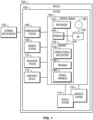
- the vehicle system 102 includes: the control module 104 that is operationally coupled to a communication system 106, an imaging system 108, a navigation system 110, a user input device 112, a display system 114, and a graphics system 116.
- the depicted vehicle system 102 is generally realized as an aircraft flight deck display system within a vehicle 100 that is an aircraft; however, the concepts presented here can be deployed in a variety of mobile platforms, such as land vehicles, spacecraft, watercraft, and the like. Accordingly, in various embodiments, the vehicle system 102 may be associated with or form part of larger aircraft management system, such as a flight management system (FMS).
- FMS flight management system
- control module 104 is coupled to the communications system 106, which is configured to support communications between external data source(s) 120 and the aircraft.
- External source(s) 120 may comprise air traffic control (ATC), or other suitable command centers and ground locations.
- Data received from the external source(s) 120 includes the instantaneous, or current, visibility report associated with a target landing location or identified runway.
- the communications system 106 may be realized using a radio communication system or another suitable data link system.
- the imaging system 108 is configured to use sensing devices to generate video or still images, and provide image data therefrom.
- the imaging system 108 may comprise one or more sensing devices, such as cameras, each with an associated sensing method. Accordingly, the video or still images generated by the imaging system 108 may be referred to herein as generated images, sensor images, or sensed images, and the image data may be referred to as sensed data.
- the imaging system 108 comprises an infrared ("IR") based video camera, low-light TV camera, or a millimeter wave (MMW) video camera.
- the IR camera senses infrared radiation to create an image in a manner that is similar to an optical camera sensing visible light to create an image.
- the imaging system 108 comprises a radar based video camera system. Radar based systems emit pulses of electromagnetic radiation and listen for, or sense, associated return echoes. The radar system may generate an image or video based upon the sensed echoes.
- the imaging system 108 may comprise a sonar system. The imaging system 108 uses methods other than visible light to generate images, and the sensing devices within the imaging system 108 are much more sensitive than a human eye. Consequently, the generated images may comprise objects, such as mountains, buildings, or ground objects, that a pilot might not otherwise see due to low visibility conditions.
- the imaging system 108 may be mounted in or near the nose of the aircraft (vehicle 100) and calibrated to align an imaging region with a viewing region of a primary flight display (PFD) or a Head Up display (HUD) rendered on the display system 114.
- the imaging system 108 may be configured so that a geometric center of its field of view (FOV) is aligned with or otherwise corresponds to the geometric center of the viewing region on the display system 114.
- FOV field of view
- the imaging system 108 may be oriented or otherwise directed substantially parallel to an anticipated line-of-sight for a pilot and/or crew member in the cockpit of the aircraft to effectively capture a forward looking cockpit view in the respective displayed image.
- the displayed images on the display system 114 are three dimensional, and the imaging system 108 generates a synthetic perspective view of terrain in front of the aircraft.
- the synthetic perspective view of terrain in front of the aircraft is generated to match the direct out-the-window view of a crew member, and may be based on the current position, attitude, and pointing information received from a navigation system 110, or other aircraft and/or flight management systems.
- Navigation system 110 is configured to provide real-time navigational data and/or information regarding operation of the aircraft.
- the navigation system 110 may be realized as a global positioning system (GPS), inertial reference system (IRS), or a radio-based navigation system (e.g., VHF omni-directional radio range (VOR) or long range aid to navigation (LORAN)), and may include one or more navigational radios or other sensors suitably configured to support operation of the navigation system 110, as will be appreciated in the art.
- the navigation system 110 is capable of obtaining and/or determining the current or instantaneous position and location information of the aircraft (e.g., the current latitude and longitude) and the current altitude or above ground level for the aircraft.
- the navigation system 110 includes inertial reference sensors capable of obtaining or otherwise determining the attitude or orientation (e.g., the pitch, roll, and yaw, heading) of the aircraft relative to earth.
- the user input device 112 is coupled to the control module 104, and the user input device 112 and the control module 104 are cooperatively configured to allow a user (e.g., a pilot, copilot, or crew member) to interact with the display system 114 and/or other elements of the vehicle system 102 in a conventional manner.
- the user input device 112 may include any one, or combination, of various known user input device devices including, but not limited to: a touch sensitive screen; a cursor control device (CCD) (not shown), such as a mouse, a trackball, or joystick; a keyboard; one or more buttons, switches, or knobs; a voice input system; and a gesture recognition system.
- CCD cursor control device
- the user input device 112 may be integrated with a display device.
- Non-limiting examples of uses for the user input device 112 include: entering values for stored variables 164, loading or updating instructions and applications 160, and loading and updating the contents of the database 156, each described in more detail below.
- the generated images from the imaging system 108 are provided to the control module 104 in the form of image data.
- the control module 104 is configured to receive the image data and convert and render the image data into display commands that command and control the renderings of the display system 114. This conversion and rendering may be performed, at least in part, by the graphics system 116.
- the graphics system 116 may be integrated within the control module 104; in other embodiments, the graphics system 116 may be integrated within the display system 114.
- the display system 114 responsive to receiving display commands from the control module 104, displays, renders, or otherwise conveys one or more graphical representations or displayed images based on the image data (i.e., sensor based images) and associated with operation of the vehicle 100, as described in greater detail below.
- images displayed on the display system 114 may also be responsive to processed user input that was received via a user input device 112.
- the display system 114 may include any device or apparatus suitable for displaying flight information or other data associated with operation of the aircraft in a format viewable by a user.
- Display methods include various types of computer generated symbols, text, and graphic information representing, for example, pitch, heading, flight path, airspeed, altitude, runway information, waypoints, targets, obstacle, terrain, and required navigation performance (RNP) data in an integrated, multi-color or monochrome form.
- the display system 114 may be part of, or include, a primary flight display (PFD) system, a panel-mounted head down display (HDD), a head up display (HUD), or a head mounted display system, such as a "near to eye display" system.
- PFD primary flight display
- HDD panel-mounted head down display
- HUD head up display
- a head mounted display system such as a "near to eye display" system.
- the control module 104 includes an interface 154, communicatively coupled to the processor 150 and memory 152 (via a bus 155), database 156, and an optional storage disk 158. In various embodiments, the control module 104 performs actions and other functions in accordance with other embodiments.
- the processor 150 may comprise any type of processor or multiple processors, single integrated circuits such as a microprocessor, or any suitable number of integrated circuit devices and/or circuit boards working in cooperation to carry out the described operations, tasks, and functions by manipulating electrical signals representing data bits at memory locations in the system memory, as well as other processing of signals.
- the memory 152, the database 156, or a disk 158 maintain data bits and may be utilized by the processor 150 as both storage and a scratch pad.
- the memory locations where data bits are maintained are physical locations that have particular electrical, magnetic, optical, or organic properties corresponding to the data bits.
- the memory 152 can be any type of suitable computer readable storage medium.
- the memory 152 may include various types of dynamic random access memory (DRAM) such as SDRAM, the various types of static RAM (SRAM), and the various types of non-volatile memory (PROM, EPROM, and flash).
- DRAM dynamic random access memory
- SRAM static RAM
- PROM non-volatile memory
- the memory 152 is located on and/or co-located on the same computer chip as the processor 150.
- the interface 154 enables communications within the control module 104, can include one or more network interfaces to communicate with other systems or components, and can be implemented using any suitable method and apparatus.
- the interface 154 enables communication from a system driver and/or another computer system.
- the interface 154 obtains data from external data source(s) 120 directly.
- the interface 154 may also include one or more network interfaces to communicate with technicians, and/or one or more storage interfaces to connect to storage apparatuses, such as the database 156.
- vehicle system 102 may differ from the embodiment depicted in FIG. 1 .
- vehicle system 102 can be integrated with an existing flight management system (FMS) or aircraft flight deck display.
- FMS flight management system
- the processor 150 loads and executes one or more programs, algorithms and rules embodied as instructions and applications 160 contained within the memory 152 and, as such, controls the general operation of the control module 104 as well as the vehicle system 102. In executing the process described herein, the processor 150 specifically loads and executes the novel program 162. Additionally, the processor 150 is configured to process received inputs (any combination of input from the communication system 106, the imaging system 108, the navigation system 110, and user input provided via user input device 112), reference the database 156 in accordance with the program 162, and generate display commands that command and control the display system 114 based thereon.
- a system and method for providing a blended taxi display for an aircraft includes a camera mounted on the aircraft that provides a real time image feed and sensors that provide data display images related to a taxi trajectory for the aircraft.
- the data display images could be provided by databases such as a navigational database that is used separately or in conjunction with sensors.
- a cockpit display device blends the real time image feed from the camera with the data display images from the sensors and/or database to generate an augmented display image for assisting a pilot during taxi operations.
- the disclosed embodiments provide additional taxi assistance/awareness for crew that fill gaps in awareness by providing taxiway guidance in a real time camera display instead of on a map or in an artificial picture.
- the taxiway information and real time camera images are blended into an "augmented reality" (AR) image that displayed on a cockpit display device.
- AR augmented reality
- the AR image is display as a two-dimensional (2D) image while in other embodiments, the AR image is displayed as a three-dimensional (3D) image.
- the AR image may displayed on a head-up display (HUD) or a helmet mounted display.
- the airport layout, taxiway details and other data is downloaded from a navigational database or other suitable source of airport data and is used to generate the data display.
- the data can be a taxiway path and other information such as labels, signs, warnings, etc.
- the data may also use color coding, distinctive shapes, etc.
- the real time camera feed come from a camera mounted onboard the aircraft (e.g., tail fin camera). It may also use a real time images from multiple cameras that are blended together.
- FIG.2 a diagram 200 is shown of a cockpit flight display with a augmented reality (AR) taxi assistant display 202 in accordance with some embodiments.
- the AR display 202 depicts a real time image from an onboard tail fin camera 204 that is blended with an overlay of data display image 206 that shows a taxiway path for the aircraft in accordance with one embodiment.
- AR augmented reality
- Skilled artisans may implement the described functionality in varying ways for each particular application, but such implementation decisions should not be interpreted as causing a departure from the scope of the present invention.
- an embodiment of a system or a component may employ various integrated circuit components, e.g., memory elements, digital signal processing elements, logic elements, look-up tables, or the like, which may carry out a variety of functions under the control of one or more microprocessors or other control devices.
- integrated circuit components e.g., memory elements, digital signal processing elements, logic elements, look-up tables, or the like, which may carry out a variety of functions under the control of one or more microprocessors or other control devices.
- DSP digital signal processor
- ASIC application specific integrated circuit
- FPGA field programmable gate array
- a general-purpose processor may be a microprocessor, but in the alternative, the processor may be any conventional processor, controller, microcontroller, or state machine.
- a processor may also be implemented as a combination of computing devices, e.g., a combination of a DSP and a microprocessor, a plurality of microprocessors, one or more microprocessors in conjunction with a DSP core, or any other such configuration.
- a software module may reside in RAM memory, flash memory, ROM memory, EPROM memory, EEPROM memory, registers, hard disk, a removable disk, a CD-ROM, or any other form of storage medium known in the art.
- An exemplary storage medium is coupled to the processor such that the processor can read information from, and write information to, the storage medium.
- the storage medium may be integral to the processor.
- the processor and the storage medium may reside in an ASIC.
- an embodiment of a system or a component may employ various integrated circuit components, e.g., memory elements, digital signal processing elements, logic elements, look-up tables, or the like, which may carry out a variety of functions under the control of one or more microprocessors or other control devices.
- integrated circuit components e.g., memory elements, digital signal processing elements, logic elements, look-up tables, or the like, which may carry out a variety of functions under the control of one or more microprocessors or other control devices.
- various elements of the systems described herein are essentially the code segments or instructions that perform the various tasks.
- the program or code segments can be stored in a processor-readable medium or transmitted by a computer data signal embodied in a carrier wave over a transmission medium or communication path.
- the "computer-readable medium”, “processor-readable medium”, or “machine-readable medium” may include any medium that can store or transfer information. Examples of the processor-readable medium include an electronic circuit, a semiconductor memory device, a ROM, a flash memory, an erasable ROM (EROM), a floppy diskette, a CD-ROM, an optical disk, a hard disk, a fiber optic medium, a radio frequency (RF) link, or the like.
- RF radio frequency
- the computer data signal may include any signal that can propagate over a transmission medium such as electronic network channels, optical fibers, air, electromagnetic paths, or RF links.
- the code segments may be downloaded via computer networks such as the Internet, an intranet, a LAN, or the like.
- modules Some of the functional units described in this specification have been referred to as "modules" in order to more particularly emphasize their implementation independence.
- functionality referred to herein as a module may be implemented wholly, or partially, as a hardware circuit comprising custom VLSI circuits or gate arrays, off-the-shelf semiconductors such as logic chips, transistors, or other discrete components.
- a module may also be implemented in programmable hardware devices such as field programmable gate arrays, programmable array logic, programmable logic devices, or the like. Modules may also be implemented in software for execution by various types of processors.
- An identified module of executable code may, for instance, comprise one or more physical or logical modules of computer instructions that may, for instance, be organized as an object, procedure, or function.
- the executables of an identified module need not be physically located together, but may comprise disparate instructions stored in different locations that, when joined logically together, comprise the module and achieve the stated purpose for the module.
- a module of executable code may be a single instruction, or many instructions, and may even be distributed over several different code segments, among different programs, and across several memory devices.
- operational data may be embodied in any suitable form and organized within any suitable type of data structure. The operational data may be collected as a single data set, or may be distributed over different locations including over different storage devices, and may exist, at least partially, merely as electronic signals on a system or network.
- the term “axial” refers to a direction that is generally parallel to or coincident with an axis of rotation, axis of symmetry, or centerline of a component or components.
- the "axial" direction may refer to the direction that generally extends in parallel to the centerline between the opposite ends or faces.
- the term “axial” may be utilized with respect to components that are not cylindrical (or otherwise radially symmetric).
- the "axial" direction for a rectangular housing containing a rotating shaft may be viewed as a direction that is generally parallel to or coincident with the rotational axis of the shaft.
- radially may refer to a direction or a relationship of components with respect to a line extending outward from a shared centerline, axis, or similar reference, for example in a plane of a cylinder or disc that is perpendicular to the centerline or axis.
- components may be viewed as “radially” aligned even though one or both of the components may not be cylindrical (or otherwise radially symmetric).
- the terms “axial” and “radial” (and any derivatives) may encompass directional relationships that are other than precisely aligned with (e.g., oblique to) the true axial and radial dimensions, provided the relationship is predominantly in the respective nominal axial or radial direction.
- the term “substantially” denotes within 5% to account for manufacturing tolerances.
- the term “about” denotes within 5% to account for manufacturing tolerances.
Landscapes
- Engineering & Computer Science (AREA)
- General Physics & Mathematics (AREA)
- Physics & Mathematics (AREA)
- Aviation & Aerospace Engineering (AREA)
- Theoretical Computer Science (AREA)
- Computer Graphics (AREA)
- General Engineering & Computer Science (AREA)
- Software Systems (AREA)
- Computer Hardware Design (AREA)
- Radar, Positioning & Navigation (AREA)
- Remote Sensing (AREA)
- Multimedia (AREA)
- Traffic Control Systems (AREA)
Applications Claiming Priority (1)
| Application Number | Priority Date | Filing Date | Title |
|---|---|---|---|
| US18/475,581 US12555486B2 (en) | 2023-09-27 | Augmented reality taxi assistant |
Publications (1)
| Publication Number | Publication Date |
|---|---|
| EP4530578A1 true EP4530578A1 (de) | 2025-04-02 |
Family
ID=92672357
Family Applications (1)
| Application Number | Title | Priority Date | Filing Date |
|---|---|---|---|
| EP24198124.0A Pending EP4530578A1 (de) | 2023-09-27 | 2024-09-03 | Taxiassistent mit erweiterter realität |
Country Status (1)
| Country | Link |
|---|---|
| EP (1) | EP4530578A1 (de) |
Citations (1)
| Publication number | Priority date | Publication date | Assignee | Title |
|---|---|---|---|---|
| US20220223052A1 (en) * | 2019-05-23 | 2022-07-14 | Smartsky Networks LLC | Augmented Reality in Aircraft Cockpit Through Bi-Directional Connectivity |
-
2024
- 2024-09-03 EP EP24198124.0A patent/EP4530578A1/de active Pending
Patent Citations (1)
| Publication number | Priority date | Publication date | Assignee | Title |
|---|---|---|---|---|
| US20220223052A1 (en) * | 2019-05-23 | 2022-07-14 | Smartsky Networks LLC | Augmented Reality in Aircraft Cockpit Through Bi-Directional Connectivity |
Also Published As
| Publication number | Publication date |
|---|---|
| US20250104567A1 (en) | 2025-03-27 |
Similar Documents
| Publication | Publication Date | Title |
|---|---|---|
| EP3509052B1 (de) | Empfehlungen für sichere geschwindigkeit für systeme zum paarweisen anflug (pa) zur flugdeckverwaltung (fim) | |
| US7212216B2 (en) | Perspective view primary flight display with terrain-tracing lines and method | |
| US8736633B2 (en) | Traffic symbology on airport moving map | |
| US7917289B2 (en) | Perspective view primary flight display system and method with range lines | |
| US8810435B2 (en) | Apparatus and method for displaying a helicopter approach to an airport landing pad | |
| US10796404B2 (en) | Aircraft systems and methods for adjusting a displayed sensor image field of view | |
| US11915603B2 (en) | Docking guidance display methods and systems | |
| US12499770B2 (en) | System and method to intuitively represent the separation of aircraft traffic | |
| EP3742421A1 (de) | Verfahren und system zur reaktivierung eines flugplans | |
| EP4567768A1 (de) | Roaas-landebahnausrichtungsanzeigen auf einer flughafenbewegungskarte | |
| EP4421452A1 (de) | Schwebevektoranzeige für vertikalanflug- und landevorgänge | |
| EP4358067A1 (de) | Verfahren und systeme zur überprüfung von flugzeugprozedur anhand eines virtuellen cursors | |
| US12555486B2 (en) | Augmented reality taxi assistant | |
| EP4530578A1 (de) | Taxiassistent mit erweiterter realität | |
| US12475796B2 (en) | Latched turn direction function and indication | |
| EP4564331A1 (de) | Verfahren und system zur bestimmung einer visuellen anflugführung für ein flugzeug | |
| US20250174136A1 (en) | Method and system for determing visual approach guidance for an aircraft | |
| US12536914B2 (en) | Method and system for taxi assist path generation based on guidance lines of an airport | |
| EP3926608A2 (de) | Anzeigeverfahren und -system zur andockführung | |
| US20200307823A1 (en) | Intelligent and ergonomic flight deck workstation | |
| EP4592644A1 (de) | Verfahren und system zur berechnung der beschleunigungsentfernungsleistung für ein vtol-flugzeug während der anflug und landung | |
| US12462690B2 (en) | System and method to display differential ground speed on a cockpit display | |
| EP4492359A1 (de) | System und verfahren zur intuitiven darstellung der trennung von flugzeugverkehr | |
| EP4418239A1 (de) | System und verfahren zur anzeige der differentiellen bodengeschwindigkeit auf einer cockpitanzeige | |
| EP3767230A1 (de) | Verfahren und system zur anzeige von objektstandorten während einer such- und rettungsoperation |
Legal Events
| Date | Code | Title | Description |
|---|---|---|---|
| PUAI | Public reference made under article 153(3) epc to a published international application that has entered the european phase |
Free format text: ORIGINAL CODE: 0009012 |
|
| STAA | Information on the status of an ep patent application or granted ep patent |
Free format text: STATUS: THE APPLICATION HAS BEEN PUBLISHED |
|
| AK | Designated contracting states |
Kind code of ref document: A1 Designated state(s): AL AT BE BG CH CY CZ DE DK EE ES FI FR GB GR HR HU IE IS IT LI LT LU LV MC ME MK MT NL NO PL PT RO RS SE SI SK SM TR |
|
| P01 | Opt-out of the competence of the unified patent court (upc) registered |
Free format text: CASE NUMBER: APP_31464/2025 Effective date: 20250630 |
|
| STAA | Information on the status of an ep patent application or granted ep patent |
Free format text: STATUS: REQUEST FOR EXAMINATION WAS MADE |
|
| 17P | Request for examination filed |
Effective date: 20250903 |