EP4530498A1 - Mechanisches leistungsübertragungssystem, leistungsübertragungsgetriebe und flugzeug - Google Patents
Mechanisches leistungsübertragungssystem, leistungsübertragungsgetriebe und flugzeug Download PDFInfo
- Publication number
- EP4530498A1 EP4530498A1 EP24182876.3A EP24182876A EP4530498A1 EP 4530498 A1 EP4530498 A1 EP 4530498A1 EP 24182876 A EP24182876 A EP 24182876A EP 4530498 A1 EP4530498 A1 EP 4530498A1
- Authority
- EP
- European Patent Office
- Prior art keywords
- transmission system
- driven
- driving
- axme
- axma
- Prior art date
- Legal status (The legal status is an assumption and is not a legal conclusion. Google has not performed a legal analysis and makes no representation as to the accuracy of the status listed.)
- Pending
Links
Images


Classifications
-
- F—MECHANICAL ENGINEERING; LIGHTING; HEATING; WEAPONS; BLASTING
- F16—ENGINEERING ELEMENTS AND UNITS; GENERAL MEASURES FOR PRODUCING AND MAINTAINING EFFECTIVE FUNCTIONING OF MACHINES OR INSTALLATIONS; THERMAL INSULATION IN GENERAL
- F16H—GEARING
- F16H57/00—General details of gearing
- F16H57/0006—Vibration-damping or noise reducing means specially adapted for gearings
-
- B—PERFORMING OPERATIONS; TRANSPORTING
- B64—AIRCRAFT; AVIATION; COSMONAUTICS
- B64D—EQUIPMENT FOR FITTING IN OR TO AIRCRAFT; FLIGHT SUITS; PARACHUTES; ARRANGEMENT OR MOUNTING OF POWER PLANTS OR PROPULSION TRANSMISSIONS IN AIRCRAFT
- B64D35/00—Transmitting power from power plants to propellers or rotors; Arrangements of transmissions
-
- B—PERFORMING OPERATIONS; TRANSPORTING
- B64—AIRCRAFT; AVIATION; COSMONAUTICS
- B64C—AEROPLANES; HELICOPTERS
- B64C27/00—Rotorcraft; Rotors peculiar thereto
- B64C27/04—Helicopters
- B64C27/12—Rotor drives
-
- F—MECHANICAL ENGINEERING; LIGHTING; HEATING; WEAPONS; BLASTING
- F16—ENGINEERING ELEMENTS AND UNITS; GENERAL MEASURES FOR PRODUCING AND MAINTAINING EFFECTIVE FUNCTIONING OF MACHINES OR INSTALLATIONS; THERMAL INSULATION IN GENERAL
- F16D—COUPLINGS FOR TRANSMITTING ROTATION; CLUTCHES; BRAKES
- F16D3/00—Yielding couplings, i.e. with means permitting movement between the connected parts during the drive
- F16D3/02—Yielding couplings, i.e. with means permitting movement between the connected parts during the drive adapted to specific functions
- F16D3/10—Couplings with means for varying the angular relationship of two coaxial shafts during motion
-
- F—MECHANICAL ENGINEERING; LIGHTING; HEATING; WEAPONS; BLASTING
- F16—ENGINEERING ELEMENTS AND UNITS; GENERAL MEASURES FOR PRODUCING AND MAINTAINING EFFECTIVE FUNCTIONING OF MACHINES OR INSTALLATIONS; THERMAL INSULATION IN GENERAL
- F16D—COUPLINGS FOR TRANSMITTING ROTATION; CLUTCHES; BRAKES
- F16D3/00—Yielding couplings, i.e. with means permitting movement between the connected parts during the drive
- F16D3/50—Yielding couplings, i.e. with means permitting movement between the connected parts during the drive with the coupling parts connected by one or more intermediate members
-
- F—MECHANICAL ENGINEERING; LIGHTING; HEATING; WEAPONS; BLASTING
- F16—ENGINEERING ELEMENTS AND UNITS; GENERAL MEASURES FOR PRODUCING AND MAINTAINING EFFECTIVE FUNCTIONING OF MACHINES OR INSTALLATIONS; THERMAL INSULATION IN GENERAL
- F16H—GEARING
- F16H57/00—General details of gearing
- F16H57/0006—Vibration-damping or noise reducing means specially adapted for gearings
- F16H2057/0012—Vibration-damping or noise reducing means specially adapted for gearings for reducing drive line oscillations
-
- F—MECHANICAL ENGINEERING; LIGHTING; HEATING; WEAPONS; BLASTING
- F16—ENGINEERING ELEMENTS AND UNITS; GENERAL MEASURES FOR PRODUCING AND MAINTAINING EFFECTIVE FUNCTIONING OF MACHINES OR INSTALLATIONS; THERMAL INSULATION IN GENERAL
- F16H—GEARING
- F16H57/00—General details of gearing
- F16H57/02—Gearboxes; Mounting gearing therein
- F16H2057/02039—Gearboxes for particular applications
-
- F—MECHANICAL ENGINEERING; LIGHTING; HEATING; WEAPONS; BLASTING
- F16—ENGINEERING ELEMENTS AND UNITS; GENERAL MEASURES FOR PRODUCING AND MAINTAINING EFFECTIVE FUNCTIONING OF MACHINES OR INSTALLATIONS; THERMAL INSULATION IN GENERAL
- F16H—GEARING
- F16H57/00—General details of gearing
- F16H57/02—Gearboxes; Mounting gearing therein
- F16H57/021—Shaft support structures, e.g. partition walls, bearing eyes, casing walls or covers with bearings
- F16H57/022—Adjustment of gear shafts or bearings
- F16H2057/0225—Adjustment of gear shafts or bearings with means for adjusting alignment
-
- F—MECHANICAL ENGINEERING; LIGHTING; HEATING; WEAPONS; BLASTING
- F16—ENGINEERING ELEMENTS AND UNITS; GENERAL MEASURES FOR PRODUCING AND MAINTAINING EFFECTIVE FUNCTIONING OF MACHINES OR INSTALLATIONS; THERMAL INSULATION IN GENERAL
- F16H—GEARING
- F16H57/00—General details of gearing
- F16H57/0018—Shaft assemblies for gearings
-
- F—MECHANICAL ENGINEERING; LIGHTING; HEATING; WEAPONS; BLASTING
- F16—ENGINEERING ELEMENTS AND UNITS; GENERAL MEASURES FOR PRODUCING AND MAINTAINING EFFECTIVE FUNCTIONING OF MACHINES OR INSTALLATIONS; THERMAL INSULATION IN GENERAL
- F16H—GEARING
- F16H57/00—General details of gearing
- F16H57/02—Gearboxes; Mounting gearing therein
- F16H57/021—Shaft support structures, e.g. partition walls, bearing eyes, casing walls or covers with bearings
-
- F—MECHANICAL ENGINEERING; LIGHTING; HEATING; WEAPONS; BLASTING
- F16—ENGINEERING ELEMENTS AND UNITS; GENERAL MEASURES FOR PRODUCING AND MAINTAINING EFFECTIVE FUNCTIONING OF MACHINES OR INSTALLATIONS; THERMAL INSULATION IN GENERAL
- F16H—GEARING
- F16H57/00—General details of gearing
- F16H57/02—Gearboxes; Mounting gearing therein
- F16H57/021—Shaft support structures, e.g. partition walls, bearing eyes, casing walls or covers with bearings
- F16H57/022—Adjustment of gear shafts or bearings
-
- F—MECHANICAL ENGINEERING; LIGHTING; HEATING; WEAPONS; BLASTING
- F16—ENGINEERING ELEMENTS AND UNITS; GENERAL MEASURES FOR PRODUCING AND MAINTAINING EFFECTIVE FUNCTIONING OF MACHINES OR INSTALLATIONS; THERMAL INSULATION IN GENERAL
- F16H—GEARING
- F16H57/00—General details of gearing
- F16H57/02—Gearboxes; Mounting gearing therein
- F16H57/028—Gearboxes; Mounting gearing therein characterised by means for reducing vibration or noise
Definitions
- the present invention lies in the field of power transmission devices.
- the present invention relates to a transmission system, a power transmission box and an aircraft, as well as a method for limiting parasitic forces in such a transmission system.
- a transmission system may have the function of mechanically transmitting power between an engine and a rotor of an aircraft.
- a known transmission system comprises a connecting device transferring rotational motion and mechanical torque from a driving shaft to a driven shaft.
- the transmission system may comprise one or more guide devices for rotationally guiding the driving shaft and the driven shaft relative to a support.
- guide devices may comprise, for example, ball or roller bearings.
- the driving shaft and the driven shaft are aligned and coaxial.
- the driving shaft and the driven shaft may be subjected to significant radial or even axial loads that may cause deformations and displacements generating radial and/or angular misalignment between them.
- Such misalignment may tend to generate parasitic forces in the power transmission system that may cause wear and/or damage to the connecting device and/or the guide devices, or even to the driving shaft and/or the driven shaft.
- the document FR 3057850 describes a transmission system comprising a first and a second shaft secured respectively to two coupling means.
- This transmission system also includes a connection system, called “flexible”, comprising at least one intermediate shaft connecting the two coupling means, and passing longitudinally through the second shaft.
- the length of the intermediate shaft can be maximized, in order to minimize the effect of a possible misalignment between the first shaft and the second shaft.
- the longer the intermediate shaft the less the parasitic forces generated by a given misalignment between the first shaft and the second shaft.
- the intermediate shaft may have intrinsic flexibility allowing it to tolerate misalignments between the first shaft and the second shaft so as to limit the parasitic forces generated.
- the connecting device may comprise special coupling means to minimize the impact of axial, radial and angular misalignments.
- These coupling means may, for example, take the form of diaphragms or plate systems.
- the document US 5286117 describes a bearing whose outer ring is asymmetrical so that its mounting in a cylindrical housing and around a shaft allows the presence of radial or axial clearance between this outer ring and the housing, only on a part of the circumference of this outer ring.
- this bearing makes it possible to reduce the stresses caused by misalignment between the inner and outer rings of the bearing in order to limit load peaks on the rolling elements of the bearing, as well as other parts of the system.
- the document FR 2988789 describes a device for axially wedging a bearing assembled on a shaft.
- This axial wedging device comprises an angular wedging means and an operating clearance allowing limited angular movement of the bearing.
- the document FR 522428 describes an elastic coupling between pinions and drive shafts belonging to transmissions in which toothed wheels can move relative to each other.
- the housing or casing of a transmission system can be very rigid to limit the extent of shaft misalignment. While effective, this solution comes at a cost in terms of mass.
- the present invention therefore aims to propose an alternative power transmission system capable of minimizing the transmission of parasitic forces, in particular between a driving shaft and a driven shaft of the transmission system during its operation.
- a transmission system comprises a driving shaft, a driven shaft and a connecting device mechanically connecting the driving shaft and the driven shaft, the driving shaft rotating the driven shaft via the connecting device.
- the connecting device allows the driving shaft to rotate the driven shaft, and consequently to transmit a rotational torque at least from the driving shaft to the driven shaft, or even also from the driven shaft to the driving shaft.
- the transmission system also comprises at least two first housings and at least two first guide devices for guiding the driving shaft in rotation around a AXMA driving shaft, each first housing receiving one of the first guide devices.
- the transmission system also comprises at least two second housings and at least two second guide devices for guiding the driven shaft in rotation around an AXME driven shaft, each second housing receiving one of the second guide devices.
- the transmission system may also include a casing in which the first and second housings are formed.
- This casing may be a single piece or composed of several assembled sub-assemblies.
- the transmission system according to the invention is particularly remarkable in that the driving axis AXMA and the driven axis AXME are misaligned when the transmission system is stopped, the driving shaft as well as the driven shaft and the connecting device being located around a center line LM of the driving axis AXMA and the driven axis AXME.
- This center line LM is defined by being, in each plane perpendicular to this center line LM, equidistant from the driving axis AXMA and the driven axis AXME.
- the driving shaft, the driven shaft and the connecting device are located around this center line LM, and are thus in line with each other, the connecting device being located between the driving shaft and the driven shaft.
- the AXMA driving and AXME driven shafts are thus close to each other, but are not coaxial when the transmission system is at a standstill, i.e. when no mechanical torque is transmitted between the driving shaft and the driven shaft.
- a gap then separates the AXMA driving shaft and the AXME driven shaft.
- the initial misalignment between the AXMA driving axis and the AXME driven axis is therefore intended to anticipate and compensate for deformations and/or displacements under load, during operation of the transmission system.
- the proximity of the AXMA driving and AXME driven shafts makes it possible, during operation, to limit, or even avoid, the appearance of parasitic forces in the transmission system, particularly at the level of the driving and driven shafts.
- the reduction or even absence of such parasitic forces also makes it possible to limit the forces experienced by the connecting device and the guiding devices of the transmission system, as well as by any speed reduction devices likely to be located upstream of the driving shaft and downstream of the driven shaft.
- the transmission system according to the invention can also make it possible to obtain a weight saving compared to solutions aimed at stiffening the transmission system.
- the misalignment at rest of the AXMA driving and AXME driven axes is compatible with the operation of the transmission system, particularly when starting it up or when a low mechanical torque is transmitted by the driving shaft to the driven shaft.
- the connecting device as well as any speed reduction devices accept such misalignment under these conditions without their operation being affected.
- the method according to the invention may comprise one or more of the following characteristics, taken alone or in combination.
- the connecting device may comprise at least one drive device allowing the driving shaft to transmit a mechanical torque to the driven shaft.
- the connecting device and/or such a driving device may not include any speed reduction device, such that the driving shaft and the driven shaft rotate at substantially the same speed when the driving shaft transmits mechanical torque to the driven shaft.
- said at least one drive device may be permanent, and similarly provide mechanical torque from the driving shaft to the driven shaft, or from the driven shaft to the driving shaft.
- said at least one drive device may be non-permanent, and in particular provide motor torque only from the driving shaft to the driven shaft.
- Said at least one drive device may, for example, comprise a device chosen from a list comprising splines, at least one key, a bolted assembly, a freewheel, a clutch, a diaphragm coupling means.
- the connecting device may comprise an intermediate shaft, said at least one drive device comprising a first drive device and a second drive device, the first drive device transmitting mechanical torque at least from the driving shaft to the intermediate shaft and the second drive device transmitting mechanical torque at least from the intermediate shaft to the driven shaft.
- the driving shaft, the intermediate shaft and the driven shaft can be substantially aligned and coaxial when the driving AXMA and driven AXME axes move under loads during operation of the transmission system.
- the driving axis AXMA and the driven axis AXME can be parallel to each other when the transmission system is stopped.
- the AXMA driving axis and the AXME driven axis may be inclined relative to each other, and therefore not parallel to each other, when the transmission system is stationary.
- the distance between the AXMA driving axis and the AXME driven axis is in this case an angular difference.
- the driving axis AXMA then passes through the first centers of rotation, and the driven axis AXME passes through the second centers of rotation.
- the driving axis AXMA is thus defined by the first centers of rotation and the driven axis AXME is defined by the second centers of rotation.
- the amount of misalignment between the driving axis AXMA and the driven axis AXME is then defined by the relative positions of the first and second centers of rotation.
- the relative positions of the first centers of rotation respectively with respect to the second centers of rotation are different.
- the first housings are cylindrical and centered on the driving axis AXMA, and the second housings are cylindrical, and are centered on the driven axis AXME when the transmission system is stopped.
- the first housings and the second housings are not coaxial.
- This eccentric outer ring comprises an outer peripheral surface and an inner peripheral surface which are eccentric relative to each other and therefore not coaxial.
- This eccentric outer ring thus makes it possible to move the center of rotation of the guide device concerned relative to the center of the housing in which the guide device concerned is arranged.
- the inner ring of a guide device is coaxial with the inner peripheral surface of the associated eccentric outer ring. Consequently, the inner ring of this guide device and the housing in which this guide device is arranged are not coaxial.
- the misalignment between the driving axis AXMA and the driven axis AXME is thus obtained by means of the eccentric outer ring of at least one of the first guide devices and the second guide devices.
- the first two guide devices each comprise a first eccentric outer ring
- the second guide devices comprising second coaxial inner and outer rings.
- the first housings and the second housings are cylindrical, and are coaxial when the transmission system is stopped, and at least one eccentric ring is inserted between on the one hand one of the first housings and second housings, and on the other hand one of the first guide devices and second guide devices.
- This eccentric ring has an outer peripheral surface and an inner peripheral surface which are eccentric with respect to each other and therefore not coaxial. In this way, this eccentric ring makes it possible to move the center of rotation of the guide device around which the eccentric ring is inserted, relative to the center of the housing in which the eccentric ring is inserted. As a result, the guide device and the housing in which this guide device is arranged are not coaxial.
- the misalignment between the AXMA driving axis and the AXME driven axis is thus obtained by means of the eccentric ring(s).
- the eccentric ring(s) For example, two eccentric rings are inserted respectively between the first housings and the first two guide devices.
- the transmission system comprises a casing composed of several assembled sub-assemblies including at least a first sub-assembly and a second sub-assembly, the first sub-assembly comprising said at least two first housings and the second sub-assembly comprising said at least two second housings.
- the first subassembly and the second subassembly are fixed to each other so that the AXMA driving axis and the AXME driven axis are misaligned when the transmission system is stopped.
- the first subassembly and the second subassembly are thus offset relative to each other, relative to a position in which the driving axis AXMA and the driven axis AXME would be aligned. when the transmission system is stopped.
- the first subassembly and the second subassembly are also offset relative to each other, relative to a position in which the first housings and the second housings are coaxial when the transmission system is stopped, the first housings and the second housings being cylindrical.
- the misalignment between the AXMA driving axis and the AXME driven axis is thus obtained by means of this offset between the first sub-assembly and the second sub-assembly.
- This offset can be obtained by the relative positions of the connection points between the first sub-assembly and the second sub-assembly, or by means of an intermediate part adapted to the desired offset.
- the first subassembly and the second subassembly may be attached directly to each other, or via the intermediate part, for example a third subassembly of the housing.
- the present invention also relates to a power transmission box comprising a transmission system as previously described.
- the power transmission box may, for example, be positioned between an engine and a propulsion device, such as a rotor if the power transmission box is fitted to an aircraft.
- the present invention also relates to an aircraft comprising a transmission system as previously described, arranged or not in a power transmission box.
- the present invention finally aims at a method of limiting parasitic forces in a transmission system as previously described.
- This method thus makes it possible to determine the value of the misalignment to be applied between the AXMA driving axis and the AXME driven axis at rest.
- the value of this misalignment can be determined based on the relative displacement between the AXMA driving axis and the AXME driven axis, itself determined by simulation and possibly confirmed by tests, or determined directly by tests.
- the relative displacement between the driving axis AXMA and the driven axis AXME may be, for example, determined when the transmission system transmits a mechanical torque from the driving shaft to the driven shaft greater than or equal to a predetermined torque.
- This predetermined torque may, for example, correspond to a particular operating phase of the transmission system, for example the operating phase that is most penalizing in terms of forces experienced by the transmission system, or the most used.
- the relative displacement between the driving axis AXMA and the driven axis AXME may alternatively be determined as being equal to an average relative displacement of the driving axis AXMA and the driven axis AXME when the transmission system transmits a mechanical torque from the driving shaft to the driven shaft which is within a predetermined interval.
- This predetermined interval may, for example, correspond to one or more operating phases of the transmission system, in particular the phases of the most penalizing operations in terms of efforts undergone and/or the most used.
- the relative displacement between the AXMA driving axis and the AXME driven axis can be determined as being equal to an average relative displacement of the AXMA driving and AXME driven axes when the transmission system is in one or more predetermined operating phases, for example the operating phase(s) which are most penalizing in terms of forces undergone or the most used.
- the most penalizing flight phases of the aircraft may be the takeoff, cruising flight, or even hovering flight phases, the most used flight phase generally being cruising flight.
- this relative displacement between the AXMA driving axis and the AXME driven axis under load can be complex to measure directly.
- parasitic forces such as a moment and/or a shear force
- the relative positions of the AXMA driving and AXME driven axes at standstill are modified by iteration to minimize these parasitic forces under load.
- FIG. 1 represents a transmission system 10 intended to transmit torque and mechanical power between a driving shaft 1 and a driven shaft 2.
- This transmission system 10 can for example be arranged between a motor and a propulsion device.
- This transmission system 10 can for example be integrated into a power transmission box 50 partially visible on the Figure 1 .
- the transmission system 10 comprises a driving shaft 1, a driven shaft 2 and a connecting device 3 mechanically connecting the driving shaft 1 and the driven shaft 2.
- the connecting device 3 secures the driving shaft 1 and the driven shaft 2 at least in one direction of rotation so that the driving shaft 1 drives the driven shaft 2 in rotation at least in this direction by transmitting a mechanical torque to it.
- the connecting device 3 comprises at least one drive device 31, 32.
- a drive device 31, 32 may, for example, comprise a freewheel making it possible to transmit a mechanical torque from the driving shaft 1 to the driven shaft 2 in a single direction of rotation.
- a drive device 31, 32 may comprise splines arranged in a complementary manner on the driving shaft 1 and driven shaft 2, at least one key, or even a bolted assembly making it possible to transmit a mechanical torque from the driving shaft 1 to the driven shaft 2 in both directions of rotation.
- a drive device 31, 32 may also comprise a clutch.
- the connecting device 3 may also comprise, according to the example of the transmission system 10 of the Figure 1 , an intermediate shaft 35, a first drive device 31 and a second drive device 32.
- the first drive device 31 transmits a mechanical torque from the driving shaft 1 to the intermediate shaft 35 and the second drive device 32 transmits a mechanical torque from the intermediate shaft 35 to the driven shaft 2.
- the first drive device 31 comprises splines and the second drive device 32 comprises a freewheel.
- the transmission system 10 also comprises at least two first housings 15, 16 and at least two respective first guide devices 5, 6 for guiding the driving shaft 1 in rotation around a driving axis AXMA.
- Each first housing 15, 16 receives one of the first guide devices 5, 6.
- the transmission system 10 comprises at least two second housings 17, 18 and at least two respective second guide devices 7, 8 making it possible to guide the driven shaft 2 in rotation around a driven axis AXME relative to a casing 54 of the power transmission box 50.
- Each second housing 17, 18 receives one of the second guide devices 7, 8.
- the first and second housings 15-18 may be cylindrical in shape and arranged/formed in the casing 54 of the power transmission box 50.
- This casing 54 may comprise several subassemblies 56-59, as shown in the Figure 1 , these subassemblies 56-59 being able to be assembled together using screws for example.
- the transmission system 10 comprises two first housings 15, 16, arranged respectively in two sub-assemblies 56, 57, and two second housings 17, 18, arranged respectively in two sub-assemblies 58, 59.
- the guide devices 5-8 comprise, for example, bearings comprising an inner ring 52, 62, 72, 82 and an outer ring 53, 63, 73, 83 framing rolling elements, namely balls or rollers for example.
- Each first guide device 5, 6 has a first center of rotation, around which the driving shaft 1 is guided in rotation.
- the driving axis AXMA thus passes through the first centers of rotation.
- each second guide device 7, 8 has a second center of rotation, around which the driven shaft 2 is guided in rotation.
- the driven axis AXME thus passes through the second centers of rotation.
- the driving axis AXMA is thus defined by the positions of the first centers of rotation and the driven axis AXME is defined by the positions of the second centers of rotation.
- the driving shaft 1 and the driven shaft 2 may also comprise teeth 14, 24 in order to cooperate respectively with an input shaft 51 and an output shaft 61 of the power transmission box 50.
- the drive shaft 1 may carry the teeth 14, the first guide devices 5, 6 guiding the drive shaft 1.
- the driving shaft 1 may comprise a driving toothed wheel 141 provided with the teeth 14.
- This driving gear wheel 141 is rotationally secured to the driving shaft 1 by a complementary drive device 12.
- the driving gear wheel 141 is guided in rotation directly or indirectly by the first guide devices 5, 6.
- the first guide devices 5, 6 guide the driving shaft 1 by guiding the driving gear wheel 141.
- This driving gear wheel 141 cooperates with an input gear wheel 514 secured to the input shaft 51. In this way, the driving shaft 1 can be rotated for example by a motor, via the input shaft 51 and the input gear wheels 514 and driving 141.
- the driven shaft 2 may comprise a driven toothed wheel 241 provided with teeth 24 cooperating with an output toothed wheel 614 rotationally fixed to the output shaft 61.
- the driven toothed wheel 241 is guided in rotation directly or indirectly by the second guide devices 7, 8. According to the example of the Figure 1 , the driven shaft 2 and the driven gear 241 form a single part.
- the driving AXMA and driven AXME shafts are misaligned, and therefore are not coaxial, when the transmission system 10 is stationary. Indeed, a gap separates the driving AXMA shaft and the driven AXME shaft when the transmission system 10 is stationary or not transmitting any torque from the driving shaft 1 to the driven shaft 2. Furthermore, the driving shaft 1 as well as the driven shaft 2 and the connecting device 3 are located around a center line LM which is in a middle position between the driving axis AXMA and the driven axis AXME.
- This gap can take the form of a distance e, as represented in the Figure 1 , the driving axis AXMA and the driven axis AXME being parallel to each other.
- This difference can take the form of an angle ⁇ , as shown in the Figure 2 , the driving axis AXMA and the driven axis AXME then being inclined relative to each other, and therefore not parallel to each other.
- This Figure 2 schematically represents only the driving shaft 1, the driven shaft 2 and the connecting device 3 as well as the driving toothed wheel 141.
- Such a misalignment between the driving AXMA and driven AXME axes can also be defined simultaneously by a distance e and an angle ⁇ .
- the distance between the AXMA driving and AXME driven axes has been deliberately exaggerated to be clearly visible.
- the distance e is for example between 0.1 and 1 millimeter (0.1 and 1 mm).
- the angle ⁇ is for example between 0.1 and 1 degrees (0.1 and 1°).
- this misalignment between the driving axis AXMA and the driven axis AXME does not prevent the operation of the transmission system 10, in particular when it is started or when a low torque is transmitted by the driving shaft 1 to the driven shaft 2.
- the connecting device 3 as well as the input 514 and output 524 toothed wheels allow such misalignment of the driving AXMA and driven AXME axes, without generating a significant parasitic force as long as the transmitted torques remain low.
- deformations and/or displacements occur in the transmission system 10 according to the invention, in particularly at the level of the driving shaft 1 and/or the driven shaft 2.
- deformations and/or displacements tend to move/deform the driving shaft 1 and/or the driven shaft 2 so as to reduce the misalignment between the driving AXMA and driven AXME axes, these driving AXMA and driven AXME axes advantageously approaching each other, possibly to the point of being coaxial and aligned.
- the misalignment of the driving AXMA and driven AXME axes is reduced, which has the effect of limiting the appearance of parasitic forces in the transmission system 10, and of limiting the effects of these parasitic forces on the transmission system 10 and its components, such as the guide devices 5-8, the casing 54, the drive device(s) 31, 32 and the teeth 14, 24, as well as the input 514 and output 524 toothed wheels, if any.
- these components are less stressed, which makes it possible to limit maintenance operations and consequently the cost of using the transmission system 10 according to the invention.
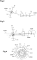
- FIG. 3 schematically represents the transmission system 10 when stationary and in operation.
- the drive shaft 1 and the drive gear 141 are shown in solid lines for the transmission system 10 when stationary, and with dotted lines for the transmission system 10 when operating.
- the driven shaft 2 and the connecting device 3 are unchanged whether the transmission system 10 is stationary or in operation.
- the driving shaft 1, shown in a solid line, and the driven shaft 2 are not coaxial, the driving AXMA and driven AXME axes being parallel to each other.
- the misalignment between the driving AXMA and driven AXME axes was defined as a function of the relative displacements under loads of the driving AXMA and driven AXME axes during operation of this transmission system 10. These displacements of the driving AXMA and driven AXME axes could be determined by simulations and/or tests.
- a method of limiting parasitic forces in the transmission system 10 can make it possible to determine the value of this initial misalignment.
- This method firstly comprises a step of determining a relative displacement between the driving axis AXMA and the driven axis AXME during operation of the transmission system 10.
- the value of this relative displacement can be determined by simulation and/or testing.
- This relative movement between the driving axis AXMA and the driven axis AXME can be determined, for example, when the transmission system 10 is in one or more particular operating phases of the transmission system 10.
- This or these particular operating phases can, for example, include the operating phase(s) that are the most penalizing in terms of forces undergone, and/or the most used.
- this relative displacement can be, for example, determined when the transmission system 10 transmits a mechanical torque from the driving shaft 1 to the driven shaft 2 greater than or equal to a predetermined torque.
- this relative displacement can be determined as being equal to an average relative displacement between the driving AXMA and driven AXME axes when the transmission system 10 transmits a mechanical torque from the driving shaft 1 to the driven shaft 2 within a predetermined interval.
- this relative displacement can be determined as being equal to an average relative displacement between the driving AXMA and driven AXME axes when the transmission system 10 operates according to the operating phase(s) which are the most penalizing in terms of forces undergone or the most used.
- this method includes a step of misaligning the driving axis AXMA and the driven axis AXME as a function of this relative displacement when the transmission system 10 is stopped.
- This method thus makes it possible to determine the value of the misalignment to be applied between the AXMA driving axis and the AXME driven axis at rest. For example, this misalignment is equal to the value of the relative displacement previously determined.
- the first center of rotation of at least one of the first guide devices 5, 6 and/or the second center of rotation of at least one of the second guide devices 7, 8 is offset relative to a theoretical position in which the driving AXMA and driven AXME axes are coaxial and aligned.
- This offset of a first or second center of rotation can be achieved only radially relative to the driving AXMA axis or the driven AXME axis, namely in a plane passing through this theoretical position and perpendicular to the AXMA driving axis or the AXME driven axis.
- This offset of the first or second center of rotation can also combine such a radial offset and an axial offset, parallel to the AXMA driving axis or the AXME driven axis.
- the first centers of rotation of all the first guide devices 5, 6 or the second centers of rotation of all the second guide devices 7, 8 may be offset to obtain the desired distance between the driving AXMA and driven AXME axes.
- the offsets will be the same for each of the first guide devices 5, 6 or the second guide devices 7, 8 if the driving AXMA and driven AXME axes are parallel to each other when the transmission system 10 is stopped.
- the offsets will be different for each of the first guide devices 5, 6 or the second guide devices 7, 8 if the driving AXMA and driven AXME axes are not parallel to each other when the transmission system 10 is stopped.
- the first centers of rotation of all the first guide devices 5,6 and the second centers of rotation of all the second guide devices 7,8 may also be offset.
- the offset of the first or second center of rotation of one or more of the first guide devices 5, 6 and/or second guide devices 7, 8 can be obtained by means of the position of the corresponding first housings 15, 16 and/or second housings 17, 18.
- the first housings 15, 16 and the second housings 17, 18 are not coaxial when the transmission system 10 is stopped, as shown in the Figure 1 .
- the first housings 15, 16 are in this case centered on the driving axis AXMA and the second housings 17, 18 are centered on the driven axis AXME.
- This offset of the first or second center of rotation of one or more of the guide devices 5-8 is, for example, obtained by machining the corresponding housing(s) 15-18 in the casing 54.
- the offset of the first or second center of rotation of one or more of the first guide devices 5, 6 and/or second guide devices 7, 8 can be obtained by means of the guide device(s) 5-8 concerned.
- the first housings 15, 16 and the second housings 17, 18 are coaxial when the transmission system 10 is stopped.
- the first or second guide device(s) 5-8 concerned are eccentric, namely that their first or second center of rotation is eccentric relative to the center of the housing 15-18 in which this guide device 5-8 is positioned.
- the offset of the first or second center of rotation of one or more of the first guide devices 5, 6 and/or second guide devices 7, 8 can be obtained using an eccentric ring 9 inserted between the housing 15-18 and the guide device 5-8 concerned.
- all of the first housings 15, 16 and the second housings 17, 18 are coaxial when the transmission system 10 is stopped.
- the first housings 15, 16 and the second housings 17, 18, and on the other hand one of the first guide devices 5, 6 and the second guide devices 7, 8 are, according to this third variant, “conventional” namely that their inner rings 52, 62, 72, 82 and outer rings 53, 63, 73, 83 are respectively coaxial two by two.
- the eccentric ring 9 comprises two outer 91 and inner 92 circular peripheral surfaces which are eccentric with respect to each other, namely that their respective centers are not coaxial.
- FIG. 5 An example of a third variant is shown in the Figure 5 , in which such an eccentric ring 9 is positioned in a first housing 15 and around a first guide device 5.
- the first housing 15 is coaxial with the other first and second housings 16-18 and centered for example on the driven axis AXME.
- the external peripheral surface 91 of the eccentric ring 9 is centered on the driven axis AXME while the internal peripheral surface 92 of this eccentric ring 9 is centered on the driving axis AXMA.
- the external peripheral surfaces 91 and internal 92 are thus eccentric and therefore not coaxial.
- the eccentricity of the eccentric ring 9 is equal to the desired offset of the first center of rotation of this first guide device 5.
- the transmission system 10 may comprise a casing 54 provided with at least a first subassembly 57 and a second subassembly 58.
- the first subassembly 57 comprises said at least two first housings 15, 16 and the second subassembly 58 comprises said at least two second housings 17, 18.
- the first subassembly 57 and the second subassembly 58 are fixed to each other so that the driving axis AXMA and the driven axis AXME are misaligned when the transmission system 10 is stopped.
- An example of a fourth variant is shown in the Figure 1 .
- the first subassembly 57 and the second subassembly 58 are thus offset relative to each other, relative to a position in which the driving axis AXMA and the driven axis AXME would be aligned when the transmission system 10 is stopped.
- the first subassembly 57 and the second subassembly 58 are offset relative to each other, relative to a position in which the first housings 15, 16 and the second housings 17, 18 are coaxial when the transmission system 10 is stopped. Consequently, following this offset, the first housings 15, 16 and the second housings 17, 18 are not coaxial when the transmission system 10 is stopped.
- the transmission system 10 can equip an aircraft 100, and in particular a power transmission box 50 of this aircraft 100, as shown in the Figure 6 .
- the transmission box of power 50 allows an engine 55 to rotate a lift rotor 102.
- the aircraft 100 may also include an auxiliary rotor 103 capable of being rotated by the engine 55, via the power transmission box 50 for example.
- the power transmission box 50 includes an input shaft 51 mechanically connected to the engine 55 and an output shaft 61 mechanically connected to the lift rotor 102.
- the particular operating phases of the transmission system 10, used in particular to determine the relative movement between the driving AXMA and driven AXME axes can be associated with flight phases of the aircraft 100, in particular the most penalizing flight phases, which can be the takeoff, cruising flight, or even hovering flight phases, and the most used flight phase which is generally cruising flight.
Landscapes
- Engineering & Computer Science (AREA)
- Mechanical Engineering (AREA)
- General Engineering & Computer Science (AREA)
- Aviation & Aerospace Engineering (AREA)
- Transmission Devices (AREA)
- Shafts, Cranks, Connecting Bars, And Related Bearings (AREA)
Applications Claiming Priority (1)
| Application Number | Priority Date | Filing Date | Title |
|---|---|---|---|
| FR2310240A FR3153388B1 (fr) | 2023-09-27 | 2023-09-27 | Système de transmission mécanique de puissance, boîte de transmission de puissance et aéronef |
Publications (1)
| Publication Number | Publication Date |
|---|---|
| EP4530498A1 true EP4530498A1 (de) | 2025-04-02 |
Family
ID=89068738
Family Applications (1)
| Application Number | Title | Priority Date | Filing Date |
|---|---|---|---|
| EP24182876.3A Pending EP4530498A1 (de) | 2023-09-27 | 2024-06-18 | Mechanisches leistungsübertragungssystem, leistungsübertragungsgetriebe und flugzeug |
Country Status (4)
| Country | Link |
|---|---|
| US (1) | US12466573B2 (de) |
| EP (1) | EP4530498A1 (de) |
| KR (1) | KR20250047109A (de) |
| FR (1) | FR3153388B1 (de) |
Citations (5)
| Publication number | Priority date | Publication date | Assignee | Title |
|---|---|---|---|---|
| FR522428A (fr) | 1919-08-04 | 1921-07-30 | Ljungstroms Angturbin Ab | Perfectionnements dans les accouplements élastiques |
| US5286117A (en) | 1992-08-17 | 1994-02-15 | Ntn Corporation | Bearing with asymmetrical flexible section |
| FR2988789A1 (fr) | 2012-03-30 | 2013-10-04 | Eurocopter France | Dispositif de calage axial d'un roulement soumis a un debattement angulaire |
| JP2016205444A (ja) * | 2015-04-16 | 2016-12-08 | Ntn株式会社 | 2モータ車両駆動装置 |
| FR3057850A1 (fr) | 2016-10-25 | 2018-04-27 | Airbus Helicopters | Systeme de transmission mecanique de puissance, boite de transmission de puissance et aeronef |
Family Cites Families (4)
| Publication number | Priority date | Publication date | Assignee | Title |
|---|---|---|---|---|
| US3051008A (en) * | 1960-09-22 | 1962-08-28 | Mech Metal Ironics Inc | Hermetically sealed rotary drive coupling |
| US20050221937A1 (en) * | 2001-11-13 | 2005-10-06 | Vladimirovich Stanovskoy V | Transmission unit provided with a swash plate (variants) and differential speed converter (variants) based thereon |
| DE102009013871B4 (de) * | 2009-03-17 | 2016-05-12 | Brose Fahrzeugteile Gmbh & Co. Kommanditgesellschaft, Coburg | Antriebseinheit mit zwei Motoreinheiten |
| JP2016151347A (ja) * | 2015-02-19 | 2016-08-22 | Ntn株式会社 | 2モータ車両駆動装置 |
-
2023
- 2023-09-27 FR FR2310240A patent/FR3153388B1/fr active Active
-
2024
- 2024-06-18 EP EP24182876.3A patent/EP4530498A1/de active Pending
- 2024-06-18 US US18/746,807 patent/US12466573B2/en active Active
- 2024-06-24 KR KR1020240082063A patent/KR20250047109A/ko active Pending
Patent Citations (5)
| Publication number | Priority date | Publication date | Assignee | Title |
|---|---|---|---|---|
| FR522428A (fr) | 1919-08-04 | 1921-07-30 | Ljungstroms Angturbin Ab | Perfectionnements dans les accouplements élastiques |
| US5286117A (en) | 1992-08-17 | 1994-02-15 | Ntn Corporation | Bearing with asymmetrical flexible section |
| FR2988789A1 (fr) | 2012-03-30 | 2013-10-04 | Eurocopter France | Dispositif de calage axial d'un roulement soumis a un debattement angulaire |
| JP2016205444A (ja) * | 2015-04-16 | 2016-12-08 | Ntn株式会社 | 2モータ車両駆動装置 |
| FR3057850A1 (fr) | 2016-10-25 | 2018-04-27 | Airbus Helicopters | Systeme de transmission mecanique de puissance, boite de transmission de puissance et aeronef |
Also Published As
| Publication number | Publication date |
|---|---|
| KR20250047109A (ko) | 2025-04-03 |
| FR3153388B1 (fr) | 2025-11-28 |
| US12466573B2 (en) | 2025-11-11 |
| US20250100702A1 (en) | 2025-03-27 |
| FR3153388A1 (fr) | 2025-03-28 |
Similar Documents
| Publication | Publication Date | Title |
|---|---|---|
| EP2524816B1 (de) | Drehkopplungsvorrichtung eines Drehkranzes an ein Rad, sowie mit einer solchen Vorrichtung ausgestattetes Fahrwerk eines Luftfahrzeugs | |
| EP2657558B1 (de) | Flexibles Kopplungsmittel und mechanische Übertragung | |
| EP3927617B1 (de) | Platzsparender und verstellbarer schaufelzapfen für turbomaschinen | |
| FR2496786A1 (fr) | Palier a capacite de deformation radiale, et dispositif amortisseur de torsion, en particulier friction d'embrayage pour vehicule automobile, comportant un tel palier | |
| FR2936775A1 (fr) | Dispositif d'entrainement des premier et deuxieme rotors de sustentation d'un giravion birotor en tandem | |
| EP4166803B1 (de) | Getriebe und zugehöriges flugzeug | |
| FR3123264A1 (fr) | Groupe motopropulseur | |
| WO2022106681A1 (fr) | Dispositif d'entraînement électrique d'un essieu d'un vehicule | |
| EP2019220B1 (de) | Flexiplatte, elastische kupplung mit einer solchen flexiplatte, flansch mit einer solchen kupplung, welle mit einer solchen flansch | |
| EP4384726A1 (de) | Drehwellenkupplung zur ermöglichung einer axialen bewegung mittels wälzkörpern | |
| FR2993920A1 (fr) | Helice non carenee a pales a calage variable pour une turbomachine | |
| EP3130815A1 (de) | Flexibles kupplungsmittel, mechanische übertragung und luftfahrzeug | |
| WO2013121137A1 (fr) | Dispositif amortisseur de torsion comportant deux voiles de sortie de couple qui sont agences de part et d'autre de rondelles d'entrée de couple | |
| EP4380858B1 (de) | Turbine mit verstellbarem anstellwinkel | |
| FR3153388A1 (fr) | Système de transmission mécanique de puissance, boîte de transmission de puissance et aéronef | |
| FR3057850B1 (fr) | Systeme de transmission mecanique de puissance, boite de transmission de puissance et aeronef | |
| EP3375075B1 (de) | Elektromechanische baugruppe mit einer an ein untersetzungsgetriebe gekoppelten elektrischen maschine | |
| EP3805583B1 (de) | Motor und/oder generator für schienenfahrzeug, entsprechendes drehgestell und schienenfahrzeug | |
| EP2160584B1 (de) | Befestigungsmittel für getriebewelle und auswuchtblock mit derartigem mittel | |
| FR3102105A1 (fr) | Chaîne de transmission pour véhicule hybride ou électrique équipée d’un batteur inertiel | |
| EP3492763B1 (de) | Mechanisches leistungsübertragungssystem, leistungsübertragungsgetriebe und luftfahrzeug | |
| EP1248919A1 (de) | Drehmomentübertragungsvorrichtung insbesondere für kraftfahrzeug | |
| EP3762625B1 (de) | Flexible kupplung mit balg und drehmoment-rückstellzähnen | |
| BE1030563B1 (fr) | Dispositif d'accouplement de deux arbres, ensemble avec le dispositif et procédé de fabrication du dispositif | |
| WO2025219669A1 (fr) | Module de soufflante a pales a calage variable |
Legal Events
| Date | Code | Title | Description |
|---|---|---|---|
| PUAI | Public reference made under article 153(3) epc to a published international application that has entered the european phase |
Free format text: ORIGINAL CODE: 0009012 |
|
| STAA | Information on the status of an ep patent application or granted ep patent |
Free format text: STATUS: THE APPLICATION HAS BEEN PUBLISHED |
|
| AK | Designated contracting states |
Kind code of ref document: A1 Designated state(s): AL AT BE BG CH CY CZ DE DK EE ES FI FR GB GR HR HU IE IS IT LI LT LU LV MC ME MK MT NL NO PL PT RO RS SE SI SK SM TR |
|
| STAA | Information on the status of an ep patent application or granted ep patent |
Free format text: STATUS: REQUEST FOR EXAMINATION WAS MADE |
|
| 17P | Request for examination filed |
Effective date: 20250404 |
|
| P01 | Opt-out of the competence of the unified patent court (upc) registered |
Free format text: CASE NUMBER: APP_16367/2025 Effective date: 20250404 |
|
| STAA | Information on the status of an ep patent application or granted ep patent |
Free format text: STATUS: EXAMINATION IS IN PROGRESS |
|
| 17Q | First examination report despatched |
Effective date: 20251215 |