EP4530495A1 - Élément de support pour composants de boîte de vitesses - Google Patents
Élément de support pour composants de boîte de vitesses Download PDFInfo
- Publication number
- EP4530495A1 EP4530495A1 EP23200014.1A EP23200014A EP4530495A1 EP 4530495 A1 EP4530495 A1 EP 4530495A1 EP 23200014 A EP23200014 A EP 23200014A EP 4530495 A1 EP4530495 A1 EP 4530495A1
- Authority
- EP
- European Patent Office
- Prior art keywords
- planetary
- sub
- gear
- support element
- planet carrier
- Prior art date
- Legal status (The legal status is an assumption and is not a legal conclusion. Google has not performed a legal analysis and makes no representation as to the accuracy of the status listed.)
- Pending
Links
- 230000005540 biological transmission Effects 0.000 description 5
- 230000005484 gravity Effects 0.000 description 3
- 230000001133 acceleration Effects 0.000 description 2
- 238000004873 anchoring Methods 0.000 description 1
- 239000000969 carrier Substances 0.000 description 1
- 230000007797 corrosion Effects 0.000 description 1
- 238000005260 corrosion Methods 0.000 description 1
- 230000002093 peripheral effect Effects 0.000 description 1
Images


Classifications
-
- F—MECHANICAL ENGINEERING; LIGHTING; HEATING; WEAPONS; BLASTING
- F16—ENGINEERING ELEMENTS AND UNITS; GENERAL MEASURES FOR PRODUCING AND MAINTAINING EFFECTIVE FUNCTIONING OF MACHINES OR INSTALLATIONS; THERMAL INSULATION IN GENERAL
- F16H—GEARING
- F16H1/00—Toothed gearings for conveying rotary motion
- F16H1/28—Toothed gearings for conveying rotary motion with gears having orbital motion
- F16H1/46—Systems consisting of a plurality of gear trains each with orbital gears, i.e. systems having three or more central gears
-
- F—MECHANICAL ENGINEERING; LIGHTING; HEATING; WEAPONS; BLASTING
- F16—ENGINEERING ELEMENTS AND UNITS; GENERAL MEASURES FOR PRODUCING AND MAINTAINING EFFECTIVE FUNCTIONING OF MACHINES OR INSTALLATIONS; THERMAL INSULATION IN GENERAL
- F16H—GEARING
- F16H57/00—General details of gearing
- F16H57/08—General details of gearing of gearings with members having orbital motion
-
- F—MECHANICAL ENGINEERING; LIGHTING; HEATING; WEAPONS; BLASTING
- F16—ENGINEERING ELEMENTS AND UNITS; GENERAL MEASURES FOR PRODUCING AND MAINTAINING EFFECTIVE FUNCTIONING OF MACHINES OR INSTALLATIONS; THERMAL INSULATION IN GENERAL
- F16H—GEARING
- F16H57/00—General details of gearing
- F16H2057/0093—Means or measures for transport, shipping or packaging
-
- F—MECHANICAL ENGINEERING; LIGHTING; HEATING; WEAPONS; BLASTING
- F16—ENGINEERING ELEMENTS AND UNITS; GENERAL MEASURES FOR PRODUCING AND MAINTAINING EFFECTIVE FUNCTIONING OF MACHINES OR INSTALLATIONS; THERMAL INSULATION IN GENERAL
- F16H—GEARING
- F16H57/00—General details of gearing
- F16H57/02—Gearboxes; Mounting gearing therein
- F16H2057/02039—Gearboxes for particular applications
- F16H2057/02078—Gearboxes for particular applications for wind turbines
-
- Y—GENERAL TAGGING OF NEW TECHNOLOGICAL DEVELOPMENTS; GENERAL TAGGING OF CROSS-SECTIONAL TECHNOLOGIES SPANNING OVER SEVERAL SECTIONS OF THE IPC; TECHNICAL SUBJECTS COVERED BY FORMER USPC CROSS-REFERENCE ART COLLECTIONS [XRACs] AND DIGESTS
- Y02—TECHNOLOGIES OR APPLICATIONS FOR MITIGATION OR ADAPTATION AGAINST CLIMATE CHANGE
- Y02E—REDUCTION OF GREENHOUSE GAS [GHG] EMISSIONS, RELATED TO ENERGY GENERATION, TRANSMISSION OR DISTRIBUTION
- Y02E10/00—Energy generation through renewable energy sources
- Y02E10/70—Wind energy
- Y02E10/72—Wind turbines with rotation axis in wind direction
Definitions
- the invention relates to a planetary gear for a wind turbine driven by a rotor, with at least one first and second planetary stage rotating in a gear housing about an axis of rotation AD , wherein the two planetary stages are drivingly connected between a sun gear of the first planetary stage and a planet carrier of the second planetary stage.
- the gearbox housing of the planetary gearhead is rigidly connected to a housing of the main bearing unit, with the rotor shaft being held rotatably relative to the housing in the main bearing unit via a bearing.
- the planet carrier of the first planetary stage is, on the one hand, drivingly connected to the rotor shaft and, on the other hand, not independently mounted in the gearbox housing.
- the planet carrier of the first planetary stage is thus indirectly mounted in the main bearing unit via the rotor shaft. This means that when the planetary gearhead is not mounted to the main bearing unit, the planet carrier of the first planetary stage is not held in place by a bearing and is in an off-center position due to gravity.
- the planet carrier of the first planetary stage be fixed in a suitable position and at least roughly centered so that no contact forces or mass acceleration forces act on the gear teeth. If contact forces and mass acceleration forces were to act, the meshing teeth of the first planetary stage could collide due to impacts or vibrations and be damaged, or be pre-damaged by fretting corrosion.
- the planetary carrier was fixed relative to the ring gear of the first planetary stage via threaded holes distributed around the outer circumference in the connecting flanges of the gearbox housing on the rotor side and/or generator side using adjustable threaded bolts.
- This solution has the disadvantage that both a rotor-side and a generator-side flange must be present on the gearbox ring gear of the first planetary stage to enable fixation.
- an anchoring option e.g., threaded holes, would have to be incorporated in the planetary carrier, thus ensuring targeted positioning of the planetary carrier relative to the threaded holes in the connecting flange. Only then is fixation in all spatial directions possible.
- the object of the invention is to show measures that enable the planet carrier to be supported for transport and assembly purposes.
- One embodiment relates to a planetary gear for a wind turbine driven by a rotor, with at least one first and second planetary stage rotating in a gear housing about an axis of rotation AD , wherein the two planetary stages are drivingly connected between a sun gear of the first planetary stage and a planet carrier of the second planetary stage, and a support element connecting the sun gear of the first planetary stage to the planet carrier of the first planetary stage and detachable as required.
- the planetary gear comprises at least two or more planetary stages.
- the last planetary stage can directly or indirectly drive a generator.
- an intermediate spur gear stage can be provided.
- the planetary carrier can be designed as a cage.
- the axis of rotation AD around which the at least one planetary stage rotates during operation, defines the axial direction.
- Planetary gears are attached to the respective planet carrier via planetary axes.
- the planetary axes run parallel and offset from the rotational axis AD .
- the planet carriers are exposed in a radially inward direction and a radially outward direction from the planet carrier or the sidewalls and are in mesh with a ring gear and a sun gear or a sun gear shaft via a respective toothing.
- the planet carrier of the first planetary stage uses its own sun gear for support and centering.
- the support element is arranged concentrically to the rotational axis AD .
- the sun gear of the first planetary stage is flexible. and connected in a rotationally fixed manner to the planet carrier of the second stage.
- the planet carrier of the second planetary stage is centrally mounted in the gearbox housing via a bearing. This ensures the correct alignment of the planet carrier with respect to the ring gear - in each case of the first planetary stage.
- sun gear refers to the functionality of the component.
- the sun gear is designed, for example, as a sun shaft, i.e. with an axial extension that extends beyond a pure toothed section.
- the support via the support element does not have to be at the center of gravity of the pre-assembled planet carrier, but the remaining tilting moment around the center of gravity of the planet carrier can be supported via the support element via further axially offset support points.
- the presence of a rotor-side connection flange between the ring gear and the rotor bearing is not necessary. This makes it possible to provide fixation and centering of the planet carrier for modern integrated drive trains using components already present within the gearbox.
- a further advantage is that the support element does not interfere with the assembly of the gearbox to the main bearing unit. The support element can remain in place, i.e. mounted, until the positioning and fixation is no longer required. Access to remove the temporarily attached support element remains available through the access through the hollow rotor shaft. This access must be used anyway to establish the connection between the rotor shaft and the planet carrier of the first planetary stage. Even before necessary disassembly, i.e.
- the support element can be attached via the hollow rotor shaft and the planet carrier can be supported on the gearbox housing.
- the planet carrier can be supported on the gearbox housing.
- the described arrangement makes it possible to fix the first planet carrier even without the presence of a rotor-side gearbox housing flange.
- the support element is held against an axial contact surface of the sun gear of the first planetary stage. This ensures that the support element can be securely attached to the sun gear.
- a screw connection is provided, via which the support element is held relative to the sun gear.
- This screw connection can, for example, comprise a single central screw or a plurality of concentrically arranged screws.
- the support element can also be partially inserted into the sun gear and supported against an inner circumferential surface of the sun gear.
- a preferred embodiment is one in which the support element is accommodated radially within a receiving volume of the planet carrier of the first planetary stage.
- the receiving volume can be cup-shaped or cylindrical.
- the support element is supported against an inner circumferential surface of the receiving volume.
- the support element is held relative to the inner circumferential surface by at least one screw connection.
- several screw elements are arranged at equal spacing around the circumference.
- the support element is held relative to the inner circumferential surface by a conical clamping element set.
- support mandrels distributed over a circumference of the transmission housing and supporting the planet carrier of the first planetary stage relative to the housing element can be provided to support the support element.
- Simple, mechanically adjustable bolts or screws can be used. It is particularly preferred if the support mandrels comprise electrically or hydraulically operated cylinder elements. The The support mandrels attached find their counterpart in a generator-side flange of the planet carrier of the first planetary stage.
- a drive train for a wind turbine for the torque-transmitting connection of a rotor to a generator comprising a main bearing unit and a main shaft and a gear driven via the main shaft, characterized in that the gear is designed as a planetary gear as described above.
- a wind turbine comprising a nacelle to which a multi-blade rotor and a generator are rotatably mounted, wherein the multi-blade rotor is connected to the generator in a torque-transmitting manner via a drive train and the drive train is designed as previously described.
- the Figure 1 shows a schematic and not to scale representation of a wind turbine 100 in a possible embodiment.
- the essential element of the wind turbine 100 is a drive train 102, which in this case structurally comprises a rotor flange 104 with a rotor 106, a main bearing unit 108, a gearbox 10 and a generator 112. At least the main bearing unit 108 and the generator 112 are supported on the machine support 114 via a tower 116 relative to a floor (not shown).
- the main bearing unit 108 comprises a main shaft 118, which is mounted rotatably about an axis of rotation AD relative to a bearing housing 120 of the main bearing unit 108 via an adjusted tapered roller bearing.
- the rotor flange 104 and the rotor 106 are held at one end of the main shaft 118.
- the other end of the main shaft 118 is rigidly connected to the gearbox 10 for driving purposes in order to introduce a drive torque generated by the rotor 106 into the gearbox 10.
- the gearbox 10 is designed as a planetary gearbox with one or more planetary stages.
- the gearbox 10 is connected to the generator 112 for driving purposes via a generator shaft 124.
- the bearing housing 120 is connected to the gearbox 10 via a flange 126.
- a reaction torque of the gearbox 10 is supported via the flange 126 relative to the machine carrier 114.
- the Figure 2 shows a section of an assembly of a planetary gear 10 and the main bearing unit 108, as it is shown, for example, in a Figure 1 illustrated wind turbine 100 can be installed. Shown are two planetary stages 14 1 and 14 2 arranged one behind the other, which are arranged in a gear housing 12 so as to rotate about an axis of rotation AD . A third planetary stage, not shown, can also be provided.
- the planetary stages 14 1 and 14 2 are constructed accordingly and each have a planet carrier 16 1 , 16 2 , a ring gear 20 1 , 20 2 , a sun gear 22 1 , 22 2 and a plurality of planet gears 18 1 , 18 2 rotating with the respective planet carrier 16 1 , 16 2 and alternately meshing with the ring gear 20 1 , 20 2 and the sun gear 22 1 , 22 2
- the planet carrier 16 2 of the second planetary stage 14 2 is supported on both sides or one side by bearings 24 on the housing-side support flanges 26.
- the second planet carrier is held largely centrally in the gear housing 12 of the planetary gear 10 via the bearings 24.
- the sun 22 1 of the first planetary stage 14 1 is connected to the planet carrier 16 2 of the second planetary stage 14 2 in a rotationally fixed and rigid manner.
- the planet carrier 16 1 of the first planetary stage 14 1 is not specifically mounted in the housing 12 but is mounted indirectly via the main bearing unit 108 after assembly via a rotationally fixed connection with the main shaft 118.
- a support element 30 is provided in the present case.
- the support element 30 can be designed as an insert in the first planetary carrier 16 1.
- the support element 30 connects the sun gear 22 1 of the first planetary stage 14 1 to the planet carrier 16 1 of the first planetary stage 14 1.
- the support element 30 is designed to be detachable and adjustable as needed, at least from the sun gear 22 1 or at least from the planet carrier 16 1 , in each case of the first planetary stage 14 1. It is preferred if the support element 30 is designed to be detachable as needed from both the sun gear 22 1 and the planet carrier 16 1 , in each case of the first planetary stage 14 1 . This offers the possibility that the support element 30 can be removed after assembly of the planetary gear 12 and the main bearing unit 108, namely through the hollow main shaft 118.
- the support element 30 positions the planet carrier 16 1 concentrically to the axis of rotation A D .
- the support element 30 is held against an axial contact surface 32 of the sun gear 22 1 of the first planetary stage 14 1 and is held, for example, relative to the sun gear 22 1 via at least one screw connection 34, which in Figure 2 is only sketched.
- the support element 30 is arranged radially within a receiving volume 36 of the planet carrier 16 1 of the first Planetary stage 14 1.
- the support element 30 is completely recessed in the receiving volume 36, so that the support element 30 is at least flush with an axial end face 38 of the first planet carrier 16 1 or - as shown - offset inwardly with respect to the end face 38.
- the support element 30 is supported against an inner circumferential surface 40 of the receiving volume 36.
- FIGs 3a) and 3b ) each show an alternative design of the support element 30 and its seat in the receiving volume 36 of the first planet carrier 16 1.
- the support element 30 is held relative to the inner circumferential surface 40 of the first planet carrier 16 1 by a conical clamping element set 44.
- the support element 30 is held, as already described, against the axial contact surface 32 of the sun gear 22 1 of the first planetary stage 14 1 and on the side of the planet carrier 16 1 against an axial contact surface 46 within the receiving volume 36.
- the support element 30 is held against this axial contact surface 46 with one or more screw connections 48.
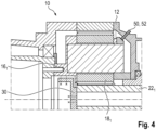
- the Figure 4 shows an additional possibility for supporting the first planetary carrier 16 1 relative to the transmission housing 12.
- several, preferably at least three, support mandrels 50 are provided, distributed over a circumference of the transmission housing 12 and supporting the planetary carrier 16 1 of the first planetary stage 14 1 relative to the transmission housing 12.
- the support mandrels 50 can comprise electrically or hydraulically operated cylinder elements 52.
Landscapes
- Engineering & Computer Science (AREA)
- General Engineering & Computer Science (AREA)
- Mechanical Engineering (AREA)
- Retarders (AREA)
Priority Applications (2)
| Application Number | Priority Date | Filing Date | Title |
|---|---|---|---|
| EP23200014.1A EP4530495A1 (fr) | 2023-09-27 | 2023-09-27 | Élément de support pour composants de boîte de vitesses |
| PCT/EP2024/077035 WO2025068355A1 (fr) | 2023-09-27 | 2024-09-26 | Élément de support pour composants de système d'engrenage |
Applications Claiming Priority (1)
| Application Number | Priority Date | Filing Date | Title |
|---|---|---|---|
| EP23200014.1A EP4530495A1 (fr) | 2023-09-27 | 2023-09-27 | Élément de support pour composants de boîte de vitesses |
Publications (1)
| Publication Number | Publication Date |
|---|---|
| EP4530495A1 true EP4530495A1 (fr) | 2025-04-02 |
Family
ID=88207473
Family Applications (1)
| Application Number | Title | Priority Date | Filing Date |
|---|---|---|---|
| EP23200014.1A Pending EP4530495A1 (fr) | 2023-09-27 | 2023-09-27 | Élément de support pour composants de boîte de vitesses |
Country Status (2)
| Country | Link |
|---|---|
| EP (1) | EP4530495A1 (fr) |
| WO (1) | WO2025068355A1 (fr) |
Citations (4)
| Publication number | Priority date | Publication date | Assignee | Title |
|---|---|---|---|---|
| DE202005013328U1 (de) * | 2005-08-24 | 2006-02-02 | Weber, Thomas | Arretier- und entsperrbare Verdreheinheit für wälzgelagerte Planetenräder in Windkraft-Planetengetrieben mit kassettenartigem Aufbau von Planetenrad, Bolzen und Lagern |
| DE102014201465A1 (de) * | 2014-01-28 | 2015-07-30 | Zf Friedrichshafen Ag | Modulare Kopplung eines Windkraftgetriebes mit einem Generator |
| US20180209512A1 (en) * | 2017-01-23 | 2018-07-26 | Flender Gmbh | Planetary gear with improved planet gear carrier support |
| DE102019214094A1 (de) | 2019-09-17 | 2021-03-18 | Zf Friedrichshafen Ag | Fixiermittel für schwere Getriebeteile |
-
2023
- 2023-09-27 EP EP23200014.1A patent/EP4530495A1/fr active Pending
-
2024
- 2024-09-26 WO PCT/EP2024/077035 patent/WO2025068355A1/fr active Pending
Patent Citations (5)
| Publication number | Priority date | Publication date | Assignee | Title |
|---|---|---|---|---|
| DE202005013328U1 (de) * | 2005-08-24 | 2006-02-02 | Weber, Thomas | Arretier- und entsperrbare Verdreheinheit für wälzgelagerte Planetenräder in Windkraft-Planetengetrieben mit kassettenartigem Aufbau von Planetenrad, Bolzen und Lagern |
| DE102014201465A1 (de) * | 2014-01-28 | 2015-07-30 | Zf Friedrichshafen Ag | Modulare Kopplung eines Windkraftgetriebes mit einem Generator |
| US20180209512A1 (en) * | 2017-01-23 | 2018-07-26 | Flender Gmbh | Planetary gear with improved planet gear carrier support |
| DE102019214094A1 (de) | 2019-09-17 | 2021-03-18 | Zf Friedrichshafen Ag | Fixiermittel für schwere Getriebeteile |
| US11635104B2 (en) * | 2019-09-17 | 2023-04-25 | Zf Friedrichshafen Ag | Fastener for heavy transmission parts |
Also Published As
| Publication number | Publication date |
|---|---|
| WO2025068355A1 (fr) | 2025-04-03 |
Similar Documents
| Publication | Publication Date | Title |
|---|---|---|
| DE112011100274B4 (de) | Fahrzeugantriebsvorrichtung | |
| EP4193071B1 (fr) | Unité d'entraînement pour véhicule | |
| EP3542057A1 (fr) | Transmission pour une éolienne | |
| DE112018007566T5 (de) | Elektrisches Brückenantriebssystem und Fahrzeug | |
| DE102007035777B4 (de) | Adapter, Planetengetriebe, Antrieb und Verfahren | |
| EP4530495A1 (fr) | Élément de support pour composants de boîte de vitesses | |
| EP2514076A1 (fr) | Ensemble génératrice pour une éolienne | |
| DE102019121079B3 (de) | Kompakte Getriebeanordnung mit Stufenplanetensatz und Stirnraddifferential | |
| DE102020207991A1 (de) | Elektrischer Antrieb | |
| DE10309874B4 (de) | Verteilerzahnradaufbau für ein Getriebe | |
| EP1915553B1 (fr) | Adaptateur, engrenage planetaire, entrainement, et procede | |
| WO2024037809A1 (fr) | Unité d'entraînement de véhicule à moteur montée sur palier à roulements | |
| EP4438921A1 (fr) | Engrenage planétaire doté d'une roue solaire stockée dans un porte-satellites | |
| WO2018024761A1 (fr) | Transmission d'éolienne | |
| EP4524432A1 (fr) | Bandage de roue creuse pour engrenage planétaire | |
| EP3913259B1 (fr) | Procédé de fabrication d'un système de changement de vitesses | |
| EP4455515A1 (fr) | Engrenage planétaire avec liaison arbre-moyeu | |
| DE102006035228B4 (de) | Adapter, Planetengetriebe, Antrieb und Verfahren | |
| EP4491908A1 (fr) | Agencement de palier, en particulier pour éoliennes | |
| EP4653716A1 (fr) | Liaison arbre-moyeu avec blocage axial | |
| DE102019118017B4 (de) | Axiale Fixierung von Planetenradbolzen in einem Planetenträger | |
| DE102019120153B3 (de) | Durch Verstemmen gesicherter Differenzialdeckel eines Planetenträgers | |
| DE202008010007U1 (de) | Anordnung zur Lagerung einer Abtriebswelle eines Automatgetriebes | |
| EP4332398A1 (fr) | Roulement d'engrenage pour une éolienne | |
| DE102023204340A1 (de) | Getriebe für ein Fahrzeug, Antriebsstrang sowie Verfahren zur Montage eines solchen Getriebes |
Legal Events
| Date | Code | Title | Description |
|---|---|---|---|
| PUAI | Public reference made under article 153(3) epc to a published international application that has entered the european phase |
Free format text: ORIGINAL CODE: 0009012 |
|
| STAA | Information on the status of an ep patent application or granted ep patent |
Free format text: STATUS: THE APPLICATION HAS BEEN PUBLISHED |
|
| AK | Designated contracting states |
Kind code of ref document: A1 Designated state(s): AL AT BE BG CH CY CZ DE DK EE ES FI FR GB GR HR HU IE IS IT LI LT LU LV MC ME MK MT NL NO PL PT RO RS SE SI SK SM TR |