EP4530485A1 - High torque transmission fastener and driving tool therefor - Google Patents
High torque transmission fastener and driving tool therefor Download PDFInfo
- Publication number
- EP4530485A1 EP4530485A1 EP24157423.5A EP24157423A EP4530485A1 EP 4530485 A1 EP4530485 A1 EP 4530485A1 EP 24157423 A EP24157423 A EP 24157423A EP 4530485 A1 EP4530485 A1 EP 4530485A1
- Authority
- EP
- European Patent Office
- Prior art keywords
- wall portions
- driving
- driven
- main body
- fastener
- Prior art date
- Legal status (The legal status is an assumption and is not a legal conclusion. Google has not performed a legal analysis and makes no representation as to the accuracy of the status listed.)
- Pending
Links
Images


Classifications
-
- F—MECHANICAL ENGINEERING; LIGHTING; HEATING; WEAPONS; BLASTING
- F16—ENGINEERING ELEMENTS AND UNITS; GENERAL MEASURES FOR PRODUCING AND MAINTAINING EFFECTIVE FUNCTIONING OF MACHINES OR INSTALLATIONS; THERMAL INSULATION IN GENERAL
- F16B—DEVICES FOR FASTENING OR SECURING CONSTRUCTIONAL ELEMENTS OR MACHINE PARTS TOGETHER, e.g. NAILS, BOLTS, CIRCLIPS, CLAMPS, CLIPS OR WEDGES; JOINTS OR JOINTING
- F16B23/00—Specially shaped nuts or heads of bolts or screws for rotations by a tool
- F16B23/0007—Specially shaped nuts or heads of bolts or screws for rotations by a tool characterised by the shape of the recess or the protrusion engaging the tool
- F16B23/003—Specially shaped nuts or heads of bolts or screws for rotations by a tool characterised by the shape of the recess or the protrusion engaging the tool star-shaped or multi-lobular, e.g. Torx-type, twelve-point star
-
- B—PERFORMING OPERATIONS; TRANSPORTING
- B25—HAND TOOLS; PORTABLE POWER-DRIVEN TOOLS; MANIPULATORS
- B25B—TOOLS OR BENCH DEVICES NOT OTHERWISE PROVIDED FOR, FOR FASTENING, CONNECTING, DISENGAGING OR HOLDING
- B25B13/00—Spanners; Wrenches
- B25B13/02—Spanners; Wrenches with rigid jaws
- B25B13/06—Spanners; Wrenches with rigid jaws of socket type
- B25B13/065—Spanners; Wrenches with rigid jaws of socket type characterised by the cross-section of the socket
-
- B—PERFORMING OPERATIONS; TRANSPORTING
- B25—HAND TOOLS; PORTABLE POWER-DRIVEN TOOLS; MANIPULATORS
- B25B—TOOLS OR BENCH DEVICES NOT OTHERWISE PROVIDED FOR, FOR FASTENING, CONNECTING, DISENGAGING OR HOLDING
- B25B15/00—Screwdrivers
- B25B15/001—Screwdrivers characterised by material or shape of the tool bit
- B25B15/004—Screwdrivers characterised by material or shape of the tool bit characterised by cross-section
- B25B15/005—Screwdrivers characterised by material or shape of the tool bit characterised by cross-section with cross- or star-shaped cross-section
-
- F—MECHANICAL ENGINEERING; LIGHTING; HEATING; WEAPONS; BLASTING
- F16—ENGINEERING ELEMENTS AND UNITS; GENERAL MEASURES FOR PRODUCING AND MAINTAINING EFFECTIVE FUNCTIONING OF MACHINES OR INSTALLATIONS; THERMAL INSULATION IN GENERAL
- F16B—DEVICES FOR FASTENING OR SECURING CONSTRUCTIONAL ELEMENTS OR MACHINE PARTS TOGETHER, e.g. NAILS, BOLTS, CIRCLIPS, CLAMPS, CLIPS OR WEDGES; JOINTS OR JOINTING
- F16B25/00—Screws that cut thread in the body into which they are screwed, e.g. wood screws
- F16B25/10—Screws performing an additional function to thread-forming, e.g. drill screws or self-piercing screws
- F16B25/103—Screws performing an additional function to thread-forming, e.g. drill screws or self-piercing screws by means of a drilling screw-point, i.e. with a cutting and material removing action
-
- F—MECHANICAL ENGINEERING; LIGHTING; HEATING; WEAPONS; BLASTING
- F16—ENGINEERING ELEMENTS AND UNITS; GENERAL MEASURES FOR PRODUCING AND MAINTAINING EFFECTIVE FUNCTIONING OF MACHINES OR INSTALLATIONS; THERMAL INSULATION IN GENERAL
- F16B—DEVICES FOR FASTENING OR SECURING CONSTRUCTIONAL ELEMENTS OR MACHINE PARTS TOGETHER, e.g. NAILS, BOLTS, CIRCLIPS, CLAMPS, CLIPS OR WEDGES; JOINTS OR JOINTING
- F16B23/00—Specially shaped nuts or heads of bolts or screws for rotations by a tool
- F16B23/0069—Specially shaped nuts or heads of bolts or screws for rotations by a tool with holes to be engaged with corresponding pins on the tool or protruding pins to be engaged with corresponding holes on the tool
Definitions
- the disclosure relates to a fastener and a tool for driving the fastener, and more particularly to a high torque transmission fastener and a driving tool therefor.
- a conventional flanged hexagon screw includes an abutting seat that is in the shape of a circular plate, and a hexagonal protrusion that protrudes from the abutting seat.
- the hexagonal protrusion of the conventional flanged hexagon screw is for a wrench or a driving tool that has a hexagonal hole to grip so that the driving tool or the wrench may drive the conventional flanged hexagon screw to rotate.
- the hexagonal protrusion has a plurality of sharp edges that are formed on an outer surface thereof, and the sharp edges may easily be worn when the conventional flanged hexagon screw is driven by the driving tool/wrench to rotate.
- the outer surface of the hexagonal protrusion may become curved, and a contact area between the hexagonal protrusion and the driving tool/wrench is decreased. A torque exerted by a user may thus not be sufficiently transmitted to the conventional flanged hexagon screw.
- the driving tool/wrench may slip off the conventional flanged hexagon screw when the user uses the driving tool/wrench to turn the conventional flanged hexagon screw. Consequently, the conventional flanged hexagon screw may not be able to be driven by the driving tool/wrench to rotate.
- an object of the disclosure is to provide a fastener that may not be worn easily and that may not cause a driving tool/wrench which drives the fastener to slip off easily.
- Another object of the disclosure is to provide a driving tool that can alleviate at least one of the drawbacks of the prior art.
- an embodiment of a fastener 1 includes a screw head 11 and a screw shank 12.
- the screw head 11 includes an abutment seat 111 that is disk-shaped and that is connected to the screw shank 12, and a driven protrusion 112 that protrudes from one side of the abutment seat 111 opposite to the screw shank 12.
- the driven protrusion 112 has four driven wall portions 113 and four guiding wall portions 114 that are disposed about a central axis of the fastener 1 in an alternating arrangement.
- the driven wall portions 113 are equiangularly spaced apart from each other.
- Each of the guiding wall portions 114 is straight, and has two opposite ends that are respectively connected to two of the driven wall portions 113 adjacent to the guiding wall portion 114.
- a ratio of a longest distance (B) between two of the driven wall portions 113 that are non-adjacent to each other to a longest distance (A) between two of the driven wall portions 113 that are adjacent to each other is greater than 1.16 (i.e., (B) divided by (A) is greater than 1.16).
- Each of the driven wall portions 113 has a curved section 115 that defines an arc of a circle and that has two opposite ends, and two straight sections 116 each of which extends from a respective one of the ends of the curved section 115 and interconnects the respective one of the ends of the curved section 115 and a respective one of two of the guiding wall portions 114 adjacent to the driven wall portion 113.
- a radius of curvature (C) of the curved section 115 of each of the driven wall portions 113 is greater than a length (D) of each of the straight sections 116 of the driven wall portion 113.
- a central angle of the curved section 115 of each of the driven wall portions 113 is smaller than 180 degrees, an arc length of the curved section 115 of each of the driven wall portions 113 on an imaginary plane perpendicular to the central axis of the fastener 1 is thus shorter than half of a circumference of the circle defined by the curved section 115 of the driven wall portion 113.
- the screw shank 12 extends from one side of the screw head 11 that is distal from the driven protrusion 112 of the screw head 11 in an axial direction of the central axis, and has a thread 121 that helically extends therealong, and an end section 122 that is formed on one end of the thread 121 opposite to the screw head 11.
- the screw shank 12 and the driven protrusion 112 are respectively connected to two opposite surfaces of the abutment seat 111 in the axial direction of the central axis.
- the abutment seat 111 may not be disk-shaped, and may be shaped differently according to actual requirements. Furthermore, in one embodiment, the abutment seat 111 may be omitted such that the driven protrusion 112 is directly connected to another end of the screw shank 12 opposite to the end section 122 of the screw shank 12.
- the end section 122 of the screw shank 12 may have different configurations according to actual requirements.
- the end section 122 is configured to be a drilling end.
- the end section 122 is configured to be a pointed end.
- the end section 122 is configured to be a blunt/flat end.
- the driven protrusion 112 of the screw head 11 has a surface opposite to the screw shank 12, and a recess 117 that is recessed from the surface along the axial direction of the central axis.
- a cross section of the recess 117 of the screw head 11 on the imaginary plane perpendicular to the central axis is configured to be one of a hexagonal shape (see FIG. 6 ), a hexalobular shape (see FIG. 7 ), a cruciform shape (see FIG. 8 ), an asterisked shape (see FIG. 9 ), a quadrilateral shape (see FIG. 10 ), and a shape of a combination of a cross and a quadrilateral (see FIG. 11 ).
- the recess 117 of the screw head 11 is adapted for a driver bit that corresponds in shape to the cross section of the recess 117 to insert thereinto. As shown in FIG. 12 , a common driver bit (E) may be used for driving the fastener 1. Thus, the fastener 1 may be used for more purposes.
- an embodiment of a driving tool 2 is adapted for driving the fastener 1, and includes a main body 21.
- the main body 21 has four driving wall portions 211 and four guiding wall portions 212 that are disposed about a central axis of the driving tool 2 in an alternating arrangement.
- the driving wall portions 211 of the main body 21 are equiangularly spaced apart from each other.
- Each of the guiding wall portions 212 of the main body 21 is straight, and has two opposite ends that are respectively connected to two of the driving wall portions 211 of the main body 21 adjacent to the guiding wall portion 212 of the main body 21.
- the driving wall portions 211 and the guiding wall portions 212 of the main body 21 cooperatively define a driving socket 213.
- a ratio of a longest distance between two of the driving wall portions 211 of the main body 21 that are non-adjacent to each other to a longest distance between two of the driving wall portions 211 of the main body 21 that are adjacent to each other is greater than 1.16.
- Each of the driving wall portions 211 of the main body 21 has a curved section 214 that defines an arc of a circle and that has two opposite ends, and two straight sections 215 each of which extends from a respective one of the ends of the curved section 214 of the main body 21 and interconnects the respective one of the ends of the curved section 214 of the main body 21 and a respective one of two of the guiding wall portions 212 of the main body 21 adjacent to the driving wall portion 211 of the main body 21.
- a radius of curvature of the curved section 214 of each of the driving wall portions 211 of the main body 21 is greater than a length of each of the straight sections 215 of the driving wall portion 211 of the main body 21.
- a central angle of the curved section 214 of each of the driving wall portions 211 of the main body 21 is smaller than 180 degrees, an arc length of the curved section 214 of each of the driving wall portions 211 on an imaginary plane perpendicular to the central axis of the driving tool 2 is thus shorter than half of a circumference of the circle defined by the curved section 214 of the driving wall portion 211.
- the driven protrusion 112 of the fastener 1 may be coupled to the driving socket 213 of the driving tool 2 that corresponds in shape thereto (i.e., the driving wall portions 211 and the guiding wall portions 212 of the driving tool 2 cooperatively surround the driven protrusion 112), or may be driven by a wrench (F) (see FIG. 15 ).
- the ratio of the longest distance (B) between two of the driven wall portions 113 that are non-adjacent to each other to the longest distance (A) between two of the driven wall portions 113 that are adjacent to each other being greater than 1.16 and greater than a ratio of a distance across corners of a regular hexagon to a distance across flats of the regular hexagon, which is 1.1547, the likelihood that the driving tool 2 or the wrench (F) slips off the fastener 1 during operation may be greatly lowered.
- a conventional wrench may slip off a conventional M10 flanged hexagon screw when a torque that is exerted on the conventional wrench is about 54 to 55 Newton meters (Nm).
- the conventional wrench when the conventional wrench is used to drive the fastener 1 that has the same outer diameter as the conventional M10 flanged hexagon screw, the conventional wrench may not slip off the fastener 1 even when a torque that is exerted on the conventional wrench reaches a maximum torque that can be applied on the fastener 1 before failure of the fastener 1 occurs, which is 88 Nm.
- the fastener 1 provides better slip resistance.
- the driving tool 2 and the fastener 1 may be able to fittingly engage with each other by the presence of the straight sections 116, 215 so that the torque exerted on the driving tool 2 may be sufficiently transmitted to the fastener 1, and that stability during the operation may be enhanced.
- the straight sections 116 the driven protrusion 112 of the fastener 1 may easily be separated from a mold during its manufacturing process.
- the mold for the driven protrusion 112 may avoid damage caused by failure to be separated from the driven protrusion 112, thereby increasing the service life of the mold for the fastener 1.
- the fastener 1 provides slip resistance and is able to avoid abrasion and damage during the operation
- the user may use the conventional wrench instead of a power tool to drive the fastener 1 when there is not enough space to operate the power tool (e.g., when the fastener 1 has to be fastened to/removed from an object adjacent to the ground), and the torque exerted on the conventional wrench may still be sufficiently transmitted to the fastener 1 while the stability during the operation is provided, thereby making the operation with hand tools relatively easy.
- the end section 122 of the screw shank 12 may have different configurations according to the actual requirements so that the fastener 1 may be used for fastening different objects.
- the driven protrusion 112 may have the recess 117 that come in different shapes so that the common driver bit (E) may be inserted into the recess 117 to drive the fastener 1.
- the fastener 1 may be used for more purposes. Therefore, the purpose of the disclosure is achieved.
Landscapes
- Engineering & Computer Science (AREA)
- General Engineering & Computer Science (AREA)
- Mechanical Engineering (AREA)
- Details Of Spanners, Wrenches, And Screw Drivers And Accessories (AREA)
Abstract
Description
- The disclosure relates to a fastener and a tool for driving the fastener, and more particularly to a high torque transmission fastener and a driving tool therefor.
- A conventional flanged hexagon screw includes an abutting seat that is in the shape of a circular plate, and a hexagonal protrusion that protrudes from the abutting seat. The hexagonal protrusion of the conventional flanged hexagon screw is for a wrench or a driving tool that has a hexagonal hole to grip so that the driving tool or the wrench may drive the conventional flanged hexagon screw to rotate. However, the hexagonal protrusion has a plurality of sharp edges that are formed on an outer surface thereof, and the sharp edges may easily be worn when the conventional flanged hexagon screw is driven by the driving tool/wrench to rotate. When the sharp edges of the hexagonal protrusion are worn, the outer surface of the hexagonal protrusion may become curved, and a contact area between the hexagonal protrusion and the driving tool/wrench is decreased. A torque exerted by a user may thus not be sufficiently transmitted to the conventional flanged hexagon screw. In addition, if the sharp edges are greatly worn out, the driving tool/wrench may slip off the conventional flanged hexagon screw when the user uses the driving tool/wrench to turn the conventional flanged hexagon screw. Consequently, the conventional flanged hexagon screw may not be able to be driven by the driving tool/wrench to rotate.
- Therefore, an object of the disclosure is to provide a fastener that may not be worn easily and that may not cause a driving tool/wrench which drives the fastener to slip off easily.
- According to an aspect of the disclosure, there is provided a fastener according to
claim 1. - Another object of the disclosure is to provide a driving tool that can alleviate at least one of the drawbacks of the prior art.
- According to an aspect of the disclosure, there is provided a driving tool according to claim 6.
- Other features and advantages of the disclosure will become apparent in the following detailed description of the embodiment(s) with reference to the accompanying drawings. It is noted that various features may not be drawn to scale.
-
FIG. 1 is a perspective view of an embodiment of a fastener according to the disclosure. -
FIG. 2 is a top view of a screw head of the fastener. -
FIG. 3 is a schematic view illustrating a driven protrusion of the screw head. -
FIGS. 4 and 5 are perspective views illustrating different configurations of the fastener. -
FIGS. 6 to 11 are top views illustrating different configurations of a recess of the driven protrusion. -
FIG. 12 is a sectional view illustrating the recess of the fastener and a conventional driver bit. -
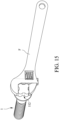
FIG. 13 is a perspective view of an embodiment of a driving tool according to the disclosure and the fastener. -
FIG. 14 is a top view of a driving socket of the driving tool. -
FIG. 15 is a schematic view illustrating a conventional wrench driving the fastener. - It should be noted herein that for clarity of description, spatially relative terms such as "top," "bottom," "upper," "lower," "on," "above," "over," "downwardly," "upwardly" and the like may be used throughout the disclosure while making reference to the features as illustrated in the drawings. The features may be oriented differently (e.g., rotated 90 degrees or at other orientations) and the spatially relative terms used herein may be interpreted accordingly.
- Referring to
FIGS. 1 to 3 , an embodiment of afastener 1 according to the disclosure includes ascrew head 11 and ascrew shank 12. Thescrew head 11 includes anabutment seat 111 that is disk-shaped and that is connected to thescrew shank 12, and a drivenprotrusion 112 that protrudes from one side of theabutment seat 111 opposite to thescrew shank 12. The drivenprotrusion 112 has four drivenwall portions 113 and four guidingwall portions 114 that are disposed about a central axis of thefastener 1 in an alternating arrangement. The drivenwall portions 113 are equiangularly spaced apart from each other. Each of the guidingwall portions 114 is straight, and has two opposite ends that are respectively connected to two of the drivenwall portions 113 adjacent to the guidingwall portion 114. A ratio of a longest distance (B) between two of the drivenwall portions 113 that are non-adjacent to each other to a longest distance (A) between two of the drivenwall portions 113 that are adjacent to each other is greater than 1.16 (i.e., (B) divided by (A) is greater than 1.16). Each of the drivenwall portions 113 has acurved section 115 that defines an arc of a circle and that has two opposite ends, and twostraight sections 116 each of which extends from a respective one of the ends of thecurved section 115 and interconnects the respective one of the ends of thecurved section 115 and a respective one of two of the guidingwall portions 114 adjacent to the drivenwall portion 113. A radius of curvature (C) of thecurved section 115 of each of the drivenwall portions 113 is greater than a length (D) of each of thestraight sections 116 of the drivenwall portion 113. A central angle of thecurved section 115 of each of the drivenwall portions 113 is smaller than 180 degrees, an arc length of thecurved section 115 of each of the drivenwall portions 113 on an imaginary plane perpendicular to the central axis of thefastener 1 is thus shorter than half of a circumference of the circle defined by thecurved section 115 of the drivenwall portion 113. Thescrew shank 12 extends from one side of thescrew head 11 that is distal from the drivenprotrusion 112 of thescrew head 11 in an axial direction of the central axis, and has athread 121 that helically extends therealong, and anend section 122 that is formed on one end of thethread 121 opposite to thescrew head 11. Specifically, in this embodiment, thescrew shank 12 and the drivenprotrusion 112 are respectively connected to two opposite surfaces of theabutment seat 111 in the axial direction of the central axis. - It is noted that, in one embodiment, the
abutment seat 111 may not be disk-shaped, and may be shaped differently according to actual requirements. Furthermore, in one embodiment, theabutment seat 111 may be omitted such that the drivenprotrusion 112 is directly connected to another end of thescrew shank 12 opposite to theend section 122 of thescrew shank 12. - Referring further to
FIGS. 4 and 5 , in cooperation withFIG. 1 , theend section 122 of thescrew shank 12 may have different configurations according to actual requirements. For example, as shown inFIG. 1 , theend section 122 is configured to be a drilling end. As shown inFIG. 4 , theend section 122 is configured to be a pointed end. As shown inFIG. 5 , theend section 122 is configured to be a blunt/flat end. Referring toFIGS. 6 to 12 , the drivenprotrusion 112 of thescrew head 11 has a surface opposite to thescrew shank 12, and arecess 117 that is recessed from the surface along the axial direction of the central axis. A cross section of therecess 117 of thescrew head 11 on the imaginary plane perpendicular to the central axis is configured to be one of a hexagonal shape (seeFIG. 6 ), a hexalobular shape (seeFIG. 7 ), a cruciform shape (seeFIG. 8 ), an asterisked shape (seeFIG. 9 ), a quadrilateral shape (seeFIG. 10 ), and a shape of a combination of a cross and a quadrilateral (seeFIG. 11 ). Therecess 117 of thescrew head 11 is adapted for a driver bit that corresponds in shape to the cross section of therecess 117 to insert thereinto. As shown inFIG. 12 , a common driver bit (E) may be used for driving thefastener 1. Thus, thefastener 1 may be used for more purposes. - Referring to
FIGS. 13 and14 , an embodiment of adriving tool 2 according to the disclosure is adapted for driving thefastener 1, and includes amain body 21. Themain body 21 has fourdriving wall portions 211 and four guidingwall portions 212 that are disposed about a central axis of thedriving tool 2 in an alternating arrangement. Thedriving wall portions 211 of themain body 21 are equiangularly spaced apart from each other. Each of the guidingwall portions 212 of themain body 21 is straight, and has two opposite ends that are respectively connected to two of thedriving wall portions 211 of themain body 21 adjacent to the guidingwall portion 212 of themain body 21. Thedriving wall portions 211 and the guidingwall portions 212 of themain body 21 cooperatively define adriving socket 213. A ratio of a longest distance between two of thedriving wall portions 211 of themain body 21 that are non-adjacent to each other to a longest distance between two of thedriving wall portions 211 of themain body 21 that are adjacent to each other is greater than 1.16. Each of thedriving wall portions 211 of themain body 21 has acurved section 214 that defines an arc of a circle and that has two opposite ends, and twostraight sections 215 each of which extends from a respective one of the ends of thecurved section 214 of themain body 21 and interconnects the respective one of the ends of thecurved section 214 of themain body 21 and a respective one of two of the guidingwall portions 212 of themain body 21 adjacent to thedriving wall portion 211 of themain body 21. A radius of curvature of thecurved section 214 of each of thedriving wall portions 211 of themain body 21 is greater than a length of each of thestraight sections 215 of thedriving wall portion 211 of themain body 21. A central angle of thecurved section 214 of each of thedriving wall portions 211 of themain body 21 is smaller than 180 degrees, an arc length of thecurved section 214 of each of thedriving wall portions 211 on an imaginary plane perpendicular to the central axis of thedriving tool 2 is thus shorter than half of a circumference of the circle defined by thecurved section 214 of thedriving wall portion 211. - Referring further to
FIG. 15 , in cooperation withFIGS. 2 and13 , the drivenprotrusion 112 of thefastener 1 may be coupled to thedriving socket 213 of thedriving tool 2 that corresponds in shape thereto (i.e., thedriving wall portions 211 and the guidingwall portions 212 of thedriving tool 2 cooperatively surround the driven protrusion 112), or may be driven by a wrench (F) (seeFIG. 15 ). By virtue of the ratio of the longest distance (B) between two of the drivenwall portions 113 that are non-adjacent to each other to the longest distance (A) between two of the drivenwall portions 113 that are adjacent to each other being greater than 1.16 and greater than a ratio of a distance across corners of a regular hexagon to a distance across flats of the regular hexagon, which is 1.1547, the likelihood that thedriving tool 2 or the wrench (F) slips off thefastener 1 during operation may be greatly lowered. According to a test, a conventional wrench may slip off a conventional M10 flanged hexagon screw when a torque that is exerted on the conventional wrench is about 54 to 55 Newton meters (Nm). However, when the conventional wrench is used to drive thefastener 1 that has the same outer diameter as the conventional M10 flanged hexagon screw, the conventional wrench may not slip off thefastener 1 even when a torque that is exerted on the conventional wrench reaches a maximum torque that can be applied on thefastener 1 before failure of thefastener 1 occurs, which is 88 Nm. Thus, thefastener 1 provides better slip resistance. - Referring to
FIGS. 2 ,13 and14 again, when a user rotates thefastener 1 via thedriving tool 2, by virtue of thecurved sections 115 of thefastener 1 and thecurved sections 214 of thedriving tool 2, thefastener 1 and thedriving tool 2 may avoid abrasion and damage during the operation, and the torque exerted on thedriving tool 2 may be sufficiently transmitted to thefastener 1. By virtue of thestraight sections driving tool 2 and thefastener 1 is increased. Although manufacturing tolerance exists in thedriving tool 2 and thefastener 1, thedriving tool 2 and thefastener 1 may be able to fittingly engage with each other by the presence of thestraight sections driving tool 2 may be sufficiently transmitted to thefastener 1, and that stability during the operation may be enhanced. Moreover, by virtue of thestraight sections 116, the drivenprotrusion 112 of thefastener 1 may easily be separated from a mold during its manufacturing process. Thus, the mold for the drivenprotrusion 112 may avoid damage caused by failure to be separated from the drivenprotrusion 112, thereby increasing the service life of the mold for thefastener 1. - In summary, because the
fastener 1 provides slip resistance and is able to avoid abrasion and damage during the operation, the user may use the conventional wrench instead of a power tool to drive thefastener 1 when there is not enough space to operate the power tool (e.g., when thefastener 1 has to be fastened to/removed from an object adjacent to the ground), and the torque exerted on the conventional wrench may still be sufficiently transmitted to thefastener 1 while the stability during the operation is provided, thereby making the operation with hand tools relatively easy. Furthermore, theend section 122 of thescrew shank 12 may have different configurations according to the actual requirements so that thefastener 1 may be used for fastening different objects. The drivenprotrusion 112 may have therecess 117 that come in different shapes so that the common driver bit (E) may be inserted into therecess 117 to drive thefastener 1. Thus, thefastener 1 may be used for more purposes. Therefore, the purpose of the disclosure is achieved. - In the description above, for the purposes of explanation, numerous specific details have been set forth in order to provide a thorough understanding of the embodiment(s). It will be apparent, however, to one skilled in the art, that one or more other embodiments may be practiced without some of these specific details. It should also be appreciated that reference throughout this specification to "one embodiment," "an embodiment," an embodiment with an indication of an ordinal number and so forth means that a particular feature, structure, or characteristic may be included in the practice of the disclosure. It should be further appreciated that in the description, various features are sometimes grouped together in a single embodiment, figure, or description thereof for the purpose of streamlining the disclosure and aiding in the understanding of various inventive aspects; such does not mean that every one of these features needs to be practiced with the presence of all the other features. In other words, in any described embodiment, when implementation of one or more features or specific details does not affect implementation of another one or more features or specific details, said one or more features may be singled out and practiced alone without said another one or more features or specific details. It should be further noted that one or more features or specific details from one embodiment may be practiced together with one or more features or specific details from another embodiment, where appropriate, in the practice of the disclosure.
Claims (7)
- A fastener (1) comprising:a screw head (11); anda screw shank (12);characterized in that:the screw head (11) includes a driven protrusion (112) that has four driven wall portions (113) and four guiding wall portions (114) which are disposed about a central axis of the fastener (1) in an alternating arrangement, the driven wall portions (113) being equiangularly spaced apart from each other, each of the guiding wall portions (114) being straight and having two opposite ends that are respectively connected to two of the driven wall portions (113) adjacent to the guiding wall portion (114), a ratio of a longest distance (B) between two of the driven wall portions (113) that are non-adjacent to each other to a longest distance (A) between two of the driven wall portions (113) that are adjacent to each other being greater than 1.16, each of the driven wall portions (113) having a curved section (115) that defines an arc of a circle and that has two opposite ends, and two straight sections (116) each of which extends from a respective one of the ends of the curved section (115) and interconnects the respective one of the ends of the curved section (115) and a respective one of two of the guiding wall portions (114) adjacent to the driven wall portion (113), a central angle of the curved section (115) of each of the driven wall portions (113) being smaller than 180 degrees; andthe screw shank (12) extends from one side of the screw head (11) that is distal from the driven protrusion (112) of the screw head (11) in an axial direction of the central axis, and has at least one thread (121) that helically extends therealong.
- The fastener (1) as claimed in claim 1, wherein a radius of curvature (C) of the curved section (115) of each of the driven wall portions (113) is greater than a length (D) of each of the straight sections (116) of the driven wall portion (113).
- The fastener (1) as claimed in any one of claims 1 and 2, wherein the driven protrusion (112) of the screw head (11) has a surface opposite to the screw shank (12), and a recess (117) that is recessed from the surface along the axial direction of the central axis.
- The fastener (1) as claimed in claim 3, wherein a cross section of the recess (117) of the screw head (11) on an imaginary plane perpendicular to the central axis is configured to be one of a hexagonal shape, a hexalobular shape, a cruciform shape, an asterisked shape, a quadrilateral shape, and a shape of a combination of a cross and a quadrilateral.
- The fastener (1) as claimed in any one of claims 1 to 4, wherein the screw head (11) further includes an abutment seat (111) that is connected to the screw shank (12), the driven protrusion (112) protruding from one side of the abutment seat (111) opposite to the screw shank (12).
- A driving tool (2) adapted for driving the fastener (1) as claimed in claim 1, the driving tool (2) comprising:a main body (21);characterized in that:
the main body (21) has four driving wall portions (211) and four guiding wall portions (212) that are disposed about a central axis of the driving tool (2) in an alternating arrangement, the driving wall portions (211) of the main body (21) being equiangularly spaced apart from each other, each of the guiding wall portions (212) of the main body (21) being straight and having two opposite ends that are respectively connected to two of the driving wall portions (211) of the main body (21) adjacent to the guiding wall portion (212) of the main body (21), the driving wall portions (211) and the guiding wall portions (212) of the main body (21) cooperatively defining a driving socket (213), a ratio of a longest distance between two of the driving wall portions (211) of the main body (21) that are non-adjacent to each other to a longest distance between two of the driving wall portions (211) of the main body (21) that are adjacent to each other being greater than 1.16, each of the driving wall portions (211) of the main body (21) having a curved section (214) that defines an arc of a circle and that has two opposite ends, and two straight sections (215) each of which extends from a respective one of the ends of the curved section (214) of the main body (21) and interconnects the respective one of the ends of the curved section (214) of the main body (21) and a respective one of two of the guiding wall portions (212) of the main body (21) adjacent to the driving wall portion (211) of the main body (21), a central angle of the curved section (214) of each of the driving wall portions (211) of the main body (21) being smaller than 180 degrees. - The driving tool (2) as claimed in claim 6, wherein a radius of curvature of the curved section (214) of each of the driving wall portions (211) of the driving tool (2) is greater than a length of each of the straight sections (215) of the driving wall portion (211) of the driving tool (2).
Applications Claiming Priority (1)
| Application Number | Priority Date | Filing Date | Title |
|---|---|---|---|
| TW112137427A TWI860862B (en) | 2023-09-28 | 2023-09-28 | High torque transmission screws and their driving tools |
Publications (1)
| Publication Number | Publication Date |
|---|---|
| EP4530485A1 true EP4530485A1 (en) | 2025-04-02 |
Family
ID=89941312
Family Applications (1)
| Application Number | Title | Priority Date | Filing Date |
|---|---|---|---|
| EP24157423.5A Pending EP4530485A1 (en) | 2023-09-28 | 2024-02-13 | High torque transmission fastener and driving tool therefor |
Country Status (5)
| Country | Link |
|---|---|
| US (1) | US20250109764A1 (en) |
| EP (1) | EP4530485A1 (en) |
| JP (1) | JP7653190B1 (en) |
| CN (1) | CN119712689A (en) |
| TW (1) | TWI860862B (en) |
Citations (2)
| Publication number | Priority date | Publication date | Assignee | Title |
|---|---|---|---|---|
| US20060228189A1 (en) * | 2005-04-06 | 2006-10-12 | Lin Chao W | Screw |
| US20090175702A1 (en) * | 2008-01-08 | 2009-07-09 | Kwantex Research Inc. | High torque transmission fastener and socket therefor |
Family Cites Families (5)
| Publication number | Priority date | Publication date | Assignee | Title |
|---|---|---|---|---|
| BE433317A (en) | 1938-03-17 | |||
| IT8452845V0 (en) * | 1984-01-17 | 1984-01-17 | Fossati Onorina | SCREW SUITABLE FOR PRECISION TIGHTENING TORQUES |
| JP2898101B2 (en) * | 1995-10-27 | 1999-05-31 | 俊次 山本 | Torque transmission member |
| CN101498333A (en) | 2008-01-30 | 2009-08-05 | 宽仕工业股份有限公司 | Screw, punch and screwdriver head |
| US8992151B2 (en) * | 2013-06-06 | 2015-03-31 | Parker Fasteners, LLC | Tamper-resistant fastener |
-
2023
- 2023-09-28 TW TW112137427A patent/TWI860862B/en active
- 2023-12-01 CN CN202311644686.3A patent/CN119712689A/en active Pending
-
2024
- 2024-01-15 JP JP2024003818A patent/JP7653190B1/en active Active
- 2024-02-13 EP EP24157423.5A patent/EP4530485A1/en active Pending
- 2024-02-14 US US18/441,294 patent/US20250109764A1/en active Pending
Patent Citations (2)
| Publication number | Priority date | Publication date | Assignee | Title |
|---|---|---|---|---|
| US20060228189A1 (en) * | 2005-04-06 | 2006-10-12 | Lin Chao W | Screw |
| US20090175702A1 (en) * | 2008-01-08 | 2009-07-09 | Kwantex Research Inc. | High torque transmission fastener and socket therefor |
Also Published As
| Publication number | Publication date |
|---|---|
| JP2025058820A (en) | 2025-04-09 |
| CN119712689A (en) | 2025-03-28 |
| JP7653190B1 (en) | 2025-03-28 |
| US20250109764A1 (en) | 2025-04-03 |
| TW202513983A (en) | 2025-04-01 |
| TWI860862B (en) | 2024-11-01 |
Similar Documents
| Publication | Publication Date | Title |
|---|---|---|
| AU2019240548B2 (en) | Socket drive improvement | |
| US5277531A (en) | Device having socket with retention surfaces | |
| HK1250688A1 (en) | Socket drive improvement | |
| CN113874170A (en) | Anti-Slip Multidirectional Fastener Removal Tool | |
| US20250001557A1 (en) | Socket drive improvement | |
| TW202128361A (en) | Advanced holding apparatus | |
| CN112638588A (en) | Fastener take-out device | |
| CN113770963A (en) | Multi-Grip Socket Bits | |
| CN1423733A (en) | Driving head for fasteners | |
| AU2023203529A1 (en) | Socket drive improvement | |
| JPS58502162A (en) | socket drive | |
| US20240109170A1 (en) | Anti-slip fastener driver | |
| EP4530485A1 (en) | High torque transmission fastener and driving tool therefor | |
| EP4530484A1 (en) | Fastener, driver bit, and punch tool | |
| EP4174331B1 (en) | Fastener, driver bit and punch tool | |
| WO2023172335A1 (en) | Selectable driver and torque tool body | |
| EP4530019A1 (en) | High torque transmission nut and driving tool therefor | |
| US20250196299A1 (en) | Anti-slip fastener driver | |
| KR20250141169A (en) | Advanced holding device | |
| CN118450968B (en) | Multi-clamping point screwdriver device | |
| TWI875403B (en) | Fastener extractor device |
Legal Events
| Date | Code | Title | Description |
|---|---|---|---|
| PUAI | Public reference made under article 153(3) epc to a published international application that has entered the european phase |
Free format text: ORIGINAL CODE: 0009012 |
|
| STAA | Information on the status of an ep patent application or granted ep patent |
Free format text: STATUS: REQUEST FOR EXAMINATION WAS MADE |
|
| 17P | Request for examination filed |
Effective date: 20241203 |
|
| AK | Designated contracting states |
Kind code of ref document: A1 Designated state(s): AL AT BE BG CH CY CZ DE DK EE ES FI FR GB GR HR HU IE IS IT LI LT LU LV MC ME MK MT NL NO PL PT RO RS SE SI SK SM TR |
|
| GRAP | Despatch of communication of intention to grant a patent |
Free format text: ORIGINAL CODE: EPIDOSNIGR1 |
|
| STAA | Information on the status of an ep patent application or granted ep patent |
Free format text: STATUS: GRANT OF PATENT IS INTENDED |
|
| RIC1 | Information provided on ipc code assigned before grant |
Ipc: F16B 23/00 20060101AFI20251110BHEP Ipc: B25B 13/06 20060101ALI20251110BHEP Ipc: B25B 15/00 20060101ALI20251110BHEP |
|
| INTG | Intention to grant announced |
Effective date: 20251125 |
|
| GRAS | Grant fee paid |
Free format text: ORIGINAL CODE: EPIDOSNIGR3 |
|
| GRAA | (expected) grant |
Free format text: ORIGINAL CODE: 0009210 |
|
| STAA | Information on the status of an ep patent application or granted ep patent |
Free format text: STATUS: THE PATENT HAS BEEN GRANTED |