EP4530484A1 - Befestigungselement, treibereinsatz und stanzwerkzeug - Google Patents
Befestigungselement, treibereinsatz und stanzwerkzeug Download PDFInfo
- Publication number
- EP4530484A1 EP4530484A1 EP24157421.9A EP24157421A EP4530484A1 EP 4530484 A1 EP4530484 A1 EP 4530484A1 EP 24157421 A EP24157421 A EP 24157421A EP 4530484 A1 EP4530484 A1 EP 4530484A1
- Authority
- EP
- European Patent Office
- Prior art keywords
- wall portions
- driver bit
- driven
- punch tool
- fastener
- Prior art date
- Legal status (The legal status is an assumption and is not a legal conclusion. Google has not performed a legal analysis and makes no representation as to the accuracy of the status listed.)
- Pending
Links
Images


Classifications
-
- F—MECHANICAL ENGINEERING; LIGHTING; HEATING; WEAPONS; BLASTING
- F16—ENGINEERING ELEMENTS AND UNITS; GENERAL MEASURES FOR PRODUCING AND MAINTAINING EFFECTIVE FUNCTIONING OF MACHINES OR INSTALLATIONS; THERMAL INSULATION IN GENERAL
- F16B—DEVICES FOR FASTENING OR SECURING CONSTRUCTIONAL ELEMENTS OR MACHINE PARTS TOGETHER, e.g. NAILS, BOLTS, CIRCLIPS, CLAMPS, CLIPS OR WEDGES; JOINTS OR JOINTING
- F16B23/00—Specially shaped nuts or heads of bolts or screws for rotations by a tool
- F16B23/0007—Specially shaped nuts or heads of bolts or screws for rotations by a tool characterised by the shape of the recess or the protrusion engaging the tool
- F16B23/003—Specially shaped nuts or heads of bolts or screws for rotations by a tool characterised by the shape of the recess or the protrusion engaging the tool star-shaped or multi-lobular, e.g. Torx-type, twelve-point star
-
- F—MECHANICAL ENGINEERING; LIGHTING; HEATING; WEAPONS; BLASTING
- F16—ENGINEERING ELEMENTS AND UNITS; GENERAL MEASURES FOR PRODUCING AND MAINTAINING EFFECTIVE FUNCTIONING OF MACHINES OR INSTALLATIONS; THERMAL INSULATION IN GENERAL
- F16B—DEVICES FOR FASTENING OR SECURING CONSTRUCTIONAL ELEMENTS OR MACHINE PARTS TOGETHER, e.g. NAILS, BOLTS, CIRCLIPS, CLAMPS, CLIPS OR WEDGES; JOINTS OR JOINTING
- F16B23/00—Specially shaped nuts or heads of bolts or screws for rotations by a tool
- F16B23/0007—Specially shaped nuts or heads of bolts or screws for rotations by a tool characterised by the shape of the recess or the protrusion engaging the tool
-
- B—PERFORMING OPERATIONS; TRANSPORTING
- B25—HAND TOOLS; PORTABLE POWER-DRIVEN TOOLS; MANIPULATORS
- B25B—TOOLS OR BENCH DEVICES NOT OTHERWISE PROVIDED FOR, FOR FASTENING, CONNECTING, DISENGAGING OR HOLDING
- B25B13/00—Spanners; Wrenches
- B25B13/02—Spanners; Wrenches with rigid jaws
- B25B13/06—Spanners; Wrenches with rigid jaws of socket type
- B25B13/065—Spanners; Wrenches with rigid jaws of socket type characterised by the cross-section of the socket
-
- B—PERFORMING OPERATIONS; TRANSPORTING
- B25—HAND TOOLS; PORTABLE POWER-DRIVEN TOOLS; MANIPULATORS
- B25B—TOOLS OR BENCH DEVICES NOT OTHERWISE PROVIDED FOR, FOR FASTENING, CONNECTING, DISENGAGING OR HOLDING
- B25B15/00—Screwdrivers
- B25B15/001—Screwdrivers characterised by material or shape of the tool bit
- B25B15/004—Screwdrivers characterised by material or shape of the tool bit characterised by cross-section
- B25B15/005—Screwdrivers characterised by material or shape of the tool bit characterised by cross-section with cross- or star-shaped cross-section
Definitions
- the disclosure relates to a fastener, a driver bit, and a punch tool, and more particularly to a fastener that is different from a conventional inner hex head fastener, a driver bit that is operable to engage the fastener, and a punch tool for forming a recess in the fastener.
- a conventional socket fastener has a recess that is generally in the shape of a hexagon (i.e., an inner hex head fastener).
- a ratio of a distance across corners of the hexagonal recess of the inner hex head fastener to a distance across flats of the hexagonal recess is smaller than 1.1547 (i.e., the ratio is smaller than a ratio of a distance across corners of a regular hexagon to a distance across flats of the regular hexagon).
- the hexagonal recess of the conventional socket fastener may not fittingly engage with a conventional driver bit, which may cause damage to the corners of the hexagonal recess when a user uses the driver bit to tighten or loosen the conventional socket fastener. Consequently, the conventional socket fastener may wear out such that the corners of the hexagonal recess may become curved, that a contact area between the conventional socket fastener and the conventional driver bit may be decreased, that a torque exerted by the user or by a power tool may not be sufficiently transmitted to the conventional socket fastener, and that the conventional socket fastener may no longer be driven by the conventional driver bit.
- the conventional socket fastener may not be successfully removed from a mold during its manufacturing process.
- a punch tool for forming the hexagonal recess of the conventional socket fastener may thus be damaged, and an overall shape and form of the hexagonal recess may thus be affected.
- an object of the disclosure is to provide a fastener that can alleviate at least one of the drawbacks of the prior art.
- Another object of the disclosure is to provide a driver bit that can alleviate at least one of the drawbacks of the prior art.
- Another object of the disclosure is to provide a punch tool that can alleviate at least one of the drawbacks of the prior art.
- Each of the driven wall portions 111 has a curved section 114 that defines an arc of a circle and that has two opposite ends, and two straight sections 115 each of which extends from a respective one of the ends of the curved section 114 and interconnects the respective one of the ends of the curved section 114 and a respective one of two of the guiding wall portions 112 adjacent to the driven wall portion 111.
- a central angle of the curved section 114 of each of the driven wall portions 111 is smaller than 180 degrees.
- a radius of curvature (C) of the curved section 114 of each of the driven wall portions 111 is greater than a length (D) of each of the straight sections 115 of the driven wall portion 111.
- the corrosion-resistant paint may easily flow out of the driven recess 113 (i.e., the corrosion-resistant paint may not clog the driven recess 113 during the coating of the fastener 1).
- a distance between the central axis of the fastener 1 and each of the driven wall portions 111 on an imaginary plane perpendicular to the central axis is greater than a distance between the central axis and each of corners of an imaginary rectangle defined by the guiding wall portions 112 on the imaginary plane.
- the driven recess 113 may be provided with more space at four corners thereof so that the fastener 1 may be driven by a conventional square driver bit. Consequently, the fastener 1 may be used for more purposes.
- the screw head 11 may be formed with an engaging recess 116 that extends from the driven recess 113 along the axial direction, and that is located below the driven wall portions 111 and the guiding wall portions 112. Specifically, when the screw head 11 is viewed from its top surface, the engaging recess 116 is located radially inwardly of the driven wall portions 111 and the guiding wall portions 112.
- the engaging recess 116 may have different configurations. As shown in Figs.
- a cross section of the engaging recess 116 of the screw head 11 on another imaginary plane perpendicular to the central axis is configured to be one of a circular shape, a quadrilateral shape, an octagonal shape, and a cross shape.
- an embodiment of a driver bit 2 is adapted for driving the fastener 1, and includes a connecting member 21, and a head end member 22 that is disposed on one end of the connecting member 21.
- the head end member 22 has four driving wall portions 221 and four guiding wall portions 222 that are disposed about a central axis of the driver bit 2 in an alternating arrangement.
- the driving wall portions 221 of the driver bit 2 are equiangularly spaced apart from each other.
- a distal edge of each of the guiding wall portions 222 of the driver bit 2 distal from the connecting member 21 is straight and has two opposite ends that are respectively connected to two of the driving wall portions 221 of the driver bit 2 adjacent to the guiding wall portion 222 of the driver bit 2.
- the driving wall portions 221 of the driver bit 2 respectively correspond in position to the driven wall portions 111 of the fastener 1
- the guiding wall portions 222 of the driver bit 2 respectively correspond in position to the guiding wall portions 112 of the fastener 1 so that the user may insert the head end member 22 into the driven recess 113 of the fastener 1, and may turn the driver bit 2 to drive the fastener 1.
- a ratio of a longest distance between two of the driving wall portions 221 of the driver bit 2 that are non-adjacent to each other to a longest distance between two of the driving wall portions 221 of the driver bit 2 that are adjacent to each other is greater than 1.16, is greater than a ratio of a distance across corners of a regular hexagon to a distance across flats of the regular hexagon, which is 1.1547, and is also greater than a current standard published by the International Organization for Standardization (ISO) for inner hex head fasteners, in which a ratio of a distance across corners of a hexagonal recess of an inner hex head fastener to a distance across flats of the hexagonal recess of the inner hex head fastener is 1.14.
- the driver bit 2 may not slip off the fastener 1.
- a distal edge of each of the driving wall portions 221 of the driver bit 2 distal from the connecting member 21 has a curved section 223 that defines an arc of a circle and that has two opposite ends, and two straight sections 224 each of which extends from a respective one of the ends of the curved section 223 of the driver bit 2 and interconnects the respective one of the ends of the curved section 223 of the driver bit 2 and a respective one of two of the guiding wall portions 222 of the driver bit 2 adjacent to the driving wall portion 221 of the driver bit 2.
- a radius of curvature of the curved section 223 of the distal edge of each of the driving wall portions 221 of the driver bit 2 is greater than a length of each of the straight sections 224 of the distal edge of the driving wall portion 221 of the driver bit 2 so that when the user uses the driver bit 2 to drive the fastener 1, a radially-outer side of the curved section 223 of the distal edge of each of the driving wall portions 221 of the driver bit 2 and the curved section 114 of each of the driven wall portions 111 of the fastener 1 may avoid abrasion and damage, and a torque exerted on the driver bit 2 may be sufficiently transmitted to the fastener 1.
- a central angle of the curved section 223 of the distal edge of each of the driving wall portions 221 of the driver bit 2 is smaller than 180 degrees, an arc length of the curved section 223 of the distal edge of each of the driving wall portions 221 of the driver bit 2 on an imaginary plane perpendicular to the central axis of the driver bit 2 is thus shorter than half of the circumference of the circle defined by the curved section 223 of the distal edge of the driving wall portion 221. Therefore, the driver bit 2 may be inserted into the driven recess 113 of the fastener 1 smoothly.
- the straight sections 224 By forming the straight sections 224, a contact area between the driver bit 2 and the driven recess 113 of the fastener 1 is increased.
- the driver bit 2 further includes an engaging member 23 that protrudes from the head end member 22, and that protrudes away from the connecting member 21 along the central axis of the driver bit 2.
- the engaging member 23 may have different configurations.
- a cross section of the engaging member 23 of the driver bit 2 on another imaginary plane perpendicular to the central axis of the driver bit 2 is configured to be a circular shape.
- a cross section of the engaging member 23 of the driver bit 2 on the another imaginary plane perpendicular to the central axis of the driver bit 2 may be one of a quadrilateral shape, an octagonal shape, and a cross shape.
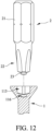
- an embodiment of a punch tool 3 is adapted for forming the driven recess 113 of the fastener 1, and includes a main body 31, and a punch head 32 that is disposed on one end of the main body 31.
- the punch head 32 has four driven wall portions 321 and four guiding wall portions 322 that are disposed about a central axis of the punch tool 3 in an alternating arrangement.
- the driven wall portions 321 of the punch tool 3 are equiangularly spaced apart from each other.
- a radius of curvature of the curved section 323 of each of the driven wall portions 321 of the punch tool 3 is greater than a length of each of the straight sections 324 of the driven wall portion 321 of the punch tool 3.
- the punch tool 3 further includes an engaging protrusion 33 that protrudes from the punch head 32, and that protrudes away from the main body 31 along the central axis of the punch tool 3.
- a cross section of the engaging protrusion 33 of the punch tool 3 on an imaginary plane perpendicular to the central axis of the punch tool 3 is configured to be one of a circular shape, a quadrilateral shape, an octagonal shape, and a cross shape so that the engaging recess 116 may be formed in a shape that corresponds to a shape of the engaging protrusion 33.
- the likelihood that the driver bit 2 slips off the driven recess 113 during operation may be greatly lowered.
- the central angle of the curved section 114 of each of the driven wall portions 111 is smaller than 180 degrees, an arc length of the curved section 114 of each of the driven wall portions 111 of the fastener 1 on the imaginary plane perpendicular to the central axis of the fastener 1 is thus shorter than half of the circumference of the circle defined by the curved section 114 of the driven wall portion 111.
- the driver bit 2 may be inserted into the driven recess 113 of the fastener 1 smoothly.
- each of the driven wall portions 111 having the curved section 114 the radially-outer side of the curved section 223 of the distal edge of each of the driving wall portions 221 of the driver bit 2 and the curved section 114 of each of the driven wall portions 111 of the fastener 1 may avoid abrasion and damage during the operation, and the torque exerted on the driver bit 2 may be sufficiently transmitted to the fastener 1.
- the straight sections 115, 224 the contact area between the driver bit 2 and the fastener 1 is increased.
- the driver bit 2 and the fastener 1 may still be able to fittingly engage with each other by the presence of the straight sections 115, 224 so that the torque exerted on the driver bit 2 may be sufficiently transmitted to the fastener 1.
- the straight sections 115, 324 the punch tool 3 may easily be separated from the fastener 1 after forming the driven recess 113, thereby lowering the likelihood that the punch tool 3 is damaged during the manufacturing process of the fastener 1. Therefore, the purpose of the disclosure is achieved.
Landscapes
- Engineering & Computer Science (AREA)
- Mechanical Engineering (AREA)
- General Engineering & Computer Science (AREA)
- Details Of Spanners, Wrenches, And Screw Drivers And Accessories (AREA)
- Connection Of Plates (AREA)
Applications Claiming Priority (1)
| Application Number | Priority Date | Filing Date | Title |
|---|---|---|---|
| TW112137429A TWI890153B (zh) | 2023-09-28 | 2023-09-28 | 緊固件、起子頭,及成型沖具 |
Publications (1)
| Publication Number | Publication Date |
|---|---|
| EP4530484A1 true EP4530484A1 (de) | 2025-04-02 |
Family
ID=89941285
Family Applications (1)
| Application Number | Title | Priority Date | Filing Date |
|---|---|---|---|
| EP24157421.9A Pending EP4530484A1 (de) | 2023-09-28 | 2024-02-13 | Befestigungselement, treibereinsatz und stanzwerkzeug |
Country Status (5)
| Country | Link |
|---|---|
| US (1) | US20250109763A1 (de) |
| EP (1) | EP4530484A1 (de) |
| JP (1) | JP7653731B1 (de) |
| CN (1) | CN119702858A (de) |
| TW (1) | TWI890153B (de) |
Citations (2)
| Publication number | Priority date | Publication date | Assignee | Title |
|---|---|---|---|---|
| US20060228189A1 (en) * | 2005-04-06 | 2006-10-12 | Lin Chao W | Screw |
| US20090175702A1 (en) * | 2008-01-08 | 2009-07-09 | Kwantex Research Inc. | High torque transmission fastener and socket therefor |
Family Cites Families (7)
| Publication number | Priority date | Publication date | Assignee | Title |
|---|---|---|---|---|
| WO1999047820A1 (es) * | 1998-03-18 | 1999-09-23 | Francisco Casino Lorite | Conjunto de tornillo y destornillador mutuamente autoagarrables |
| CN1862036A (zh) * | 2005-05-10 | 2006-11-15 | 宽仕工业股份有限公司 | 螺丝、冲具与起子头 |
| US20070207009A1 (en) * | 2006-03-06 | 2007-09-06 | Teng-Hung Lin | Screw with a recess in the head of the screw |
| SG147344A1 (en) * | 2007-05-02 | 2008-11-28 | Unisteel Technology Ltd | Screw head recess drive and corresponding driver tool and recess punch |
| CN101498333A (zh) * | 2008-01-30 | 2009-08-05 | 宽仕工业股份有限公司 | 螺丝、冲具及起子头 |
| US8291795B2 (en) * | 2010-03-02 | 2012-10-23 | Phillips Screw Company | Fastener system with stable engagement and stick fit |
| JP6118852B2 (ja) * | 2015-08-06 | 2017-04-19 | 株式会社九飛勢螺 | ねじ |
-
2023
- 2023-09-28 TW TW112137429A patent/TWI890153B/zh active
- 2023-12-01 CN CN202311644720.7A patent/CN119702858A/zh active Pending
-
2024
- 2024-01-15 JP JP2024003872A patent/JP7653731B1/ja active Active
- 2024-02-13 EP EP24157421.9A patent/EP4530484A1/de active Pending
- 2024-02-14 US US18/441,284 patent/US20250109763A1/en active Pending
Patent Citations (2)
| Publication number | Priority date | Publication date | Assignee | Title |
|---|---|---|---|---|
| US20060228189A1 (en) * | 2005-04-06 | 2006-10-12 | Lin Chao W | Screw |
| US20090175702A1 (en) * | 2008-01-08 | 2009-07-09 | Kwantex Research Inc. | High torque transmission fastener and socket therefor |
Also Published As
| Publication number | Publication date |
|---|---|
| US20250109763A1 (en) | 2025-04-03 |
| JP2025058821A (ja) | 2025-04-09 |
| TW202513984A (zh) | 2025-04-01 |
| JP7653731B1 (ja) | 2025-03-31 |
| TWI890153B (zh) | 2025-07-11 |
| CN119702858A (zh) | 2025-03-28 |
Similar Documents
| Publication | Publication Date | Title |
|---|---|---|
| AU2019240548B2 (en) | Socket drive improvement | |
| US20220032362A1 (en) | Workpieces for making fasteners and tools | |
| CN102791432B (zh) | 具有稳定的接合和卡紧配合的紧固件系统 | |
| HK1250688A1 (en) | Socket drive improvement | |
| US20250001557A1 (en) | Socket drive improvement | |
| US6729208B1 (en) | Tool for removing fasteners | |
| EP2283241A1 (de) | Antriebssystem | |
| US4705441A (en) | Self locking sheet metal screw | |
| JP2018530439A (ja) | テーパ状のローブ状ドライバ及び締結具 | |
| CA3124034C (en) | Socket drive improvement | |
| US20230321799A1 (en) | Anti-Slip Fastener Driver | |
| JPS58502162A (ja) | ソケツト・ドライブ | |
| US8707830B2 (en) | Socket | |
| EP4530484A1 (de) | Befestigungselement, treibereinsatz und stanzwerkzeug | |
| US20250188975A1 (en) | Fastener, driver bit and punch tool | |
| EP4530485A1 (de) | Befestigungselement mit hoher drehmomentübertragung und antriebswerkzeug dafür | |
| EP4530019A1 (de) | Übertragungsmutter mit hohem drehmoment und antriebswerkzeug dafür | |
| EP0961042A1 (de) | Durch Bedienung von zugehörigen Werkzeugen drehender Kopf für Vorrichtungen, mit innerer Ausnehmung zum Eingriff mit diesen Werkzeugen | |
| US20250196299A1 (en) | Anti-slip fastener driver | |
| CN110856910A (zh) | 防滑套筒 |
Legal Events
| Date | Code | Title | Description |
|---|---|---|---|
| PUAI | Public reference made under article 153(3) epc to a published international application that has entered the european phase |
Free format text: ORIGINAL CODE: 0009012 |
|
| STAA | Information on the status of an ep patent application or granted ep patent |
Free format text: STATUS: REQUEST FOR EXAMINATION WAS MADE |
|
| 17P | Request for examination filed |
Effective date: 20241203 |
|
| AK | Designated contracting states |
Kind code of ref document: A1 Designated state(s): AL AT BE BG CH CY CZ DE DK EE ES FI FR GB GR HR HU IE IS IT LI LT LU LV MC ME MK MT NL NO PL PT RO RS SE SI SK SM TR |
|
| STAA | Information on the status of an ep patent application or granted ep patent |
Free format text: STATUS: EXAMINATION IS IN PROGRESS |