EP4530483A1 - Fastening device for fastening a mechanical element with a support structure, fastening system, attachment method as well as detachment method - Google Patents
Fastening device for fastening a mechanical element with a support structure, fastening system, attachment method as well as detachment method Download PDFInfo
- Publication number
- EP4530483A1 EP4530483A1 EP23200355.8A EP23200355A EP4530483A1 EP 4530483 A1 EP4530483 A1 EP 4530483A1 EP 23200355 A EP23200355 A EP 23200355A EP 4530483 A1 EP4530483 A1 EP 4530483A1
- Authority
- EP
- European Patent Office
- Prior art keywords
- fastening device
- locking bolt
- fastening
- support structure
- locking
- Prior art date
- Legal status (The legal status is an assumption and is not a legal conclusion. Google has not performed a legal analysis and makes no representation as to the accuracy of the status listed.)
- Pending
Links
Images




Classifications
-
- F—MECHANICAL ENGINEERING; LIGHTING; HEATING; WEAPONS; BLASTING
- F16—ENGINEERING ELEMENTS AND UNITS; GENERAL MEASURES FOR PRODUCING AND MAINTAINING EFFECTIVE FUNCTIONING OF MACHINES OR INSTALLATIONS; THERMAL INSULATION IN GENERAL
- F16B—DEVICES FOR FASTENING OR SECURING CONSTRUCTIONAL ELEMENTS OR MACHINE PARTS TOGETHER, e.g. NAILS, BOLTS, CIRCLIPS, CLAMPS, CLIPS OR WEDGES; JOINTS OR JOINTING
- F16B21/00—Means for preventing relative axial movement of a pin, spigot, shaft or the like and a member surrounding it; Stud-and-socket releasable fastenings
- F16B21/06—Releasable fastening devices with snap-action
- F16B21/07—Releasable fastening devices with snap-action in which the socket has a resilient part
- F16B21/073—Releasable fastening devices with snap-action in which the socket has a resilient part the socket having a resilient part on its inside
-
- B—PERFORMING OPERATIONS; TRANSPORTING
- B64—AIRCRAFT; AVIATION; COSMONAUTICS
- B64F—GROUND OR AIRCRAFT-CARRIER-DECK INSTALLATIONS SPECIALLY ADAPTED FOR USE IN CONNECTION WITH AIRCRAFT; DESIGNING, MANUFACTURING, ASSEMBLING, CLEANING, MAINTAINING OR REPAIRING AIRCRAFT, NOT OTHERWISE PROVIDED FOR; HANDLING, TRANSPORTING, TESTING OR INSPECTING AIRCRAFT COMPONENTS, NOT OTHERWISE PROVIDED FOR
- B64F5/00—Designing, manufacturing, assembling, cleaning, maintaining or repairing aircraft, not otherwise provided for; Handling, transporting, testing or inspecting aircraft components, not otherwise provided for
- B64F5/10—Manufacturing or assembling aircraft, e.g. jigs therefor
-
- F—MECHANICAL ENGINEERING; LIGHTING; HEATING; WEAPONS; BLASTING
- F16—ENGINEERING ELEMENTS AND UNITS; GENERAL MEASURES FOR PRODUCING AND MAINTAINING EFFECTIVE FUNCTIONING OF MACHINES OR INSTALLATIONS; THERMAL INSULATION IN GENERAL
- F16B—DEVICES FOR FASTENING OR SECURING CONSTRUCTIONAL ELEMENTS OR MACHINE PARTS TOGETHER, e.g. NAILS, BOLTS, CIRCLIPS, CLAMPS, CLIPS OR WEDGES; JOINTS OR JOINTING
- F16B35/00—Screw-bolts; Stay-bolts; Screw-threaded studs; Screws; Set screws
- F16B35/04—Screw-bolts; Stay-bolts; Screw-threaded studs; Screws; Set screws with specially-shaped head or shaft in order to fix the bolt on or in an object
- F16B35/041—Specially-shaped shafts
- F16B35/048—Specially-shaped necks
-
- F—MECHANICAL ENGINEERING; LIGHTING; HEATING; WEAPONS; BLASTING
- F16—ENGINEERING ELEMENTS AND UNITS; GENERAL MEASURES FOR PRODUCING AND MAINTAINING EFFECTIVE FUNCTIONING OF MACHINES OR INSTALLATIONS; THERMAL INSULATION IN GENERAL
- F16B—DEVICES FOR FASTENING OR SECURING CONSTRUCTIONAL ELEMENTS OR MACHINE PARTS TOGETHER, e.g. NAILS, BOLTS, CIRCLIPS, CLAMPS, CLIPS OR WEDGES; JOINTS OR JOINTING
- F16B37/00—Nuts or like thread-engaging members
- F16B37/08—Quickly-detachable or mountable nuts, e.g. consisting of two or more parts; Nuts movable along the bolt after tilting the nut
- F16B37/0807—Nuts engaged from the end of the bolt, e.g. axially slidable nuts
- F16B37/0857—Nuts engaged from the end of the bolt, e.g. axially slidable nuts with the threaded portions of the nut engaging the thread of the bolt by the action of one or more springs or resilient retaining members
-
- B—PERFORMING OPERATIONS; TRANSPORTING
- B64—AIRCRAFT; AVIATION; COSMONAUTICS
- B64C—AEROPLANES; HELICOPTERS
- B64C1/00—Fuselages; Constructional features common to fuselages, wings, stabilising surfaces or the like
- B64C1/06—Frames; Stringers; Longerons ; Fuselage sections
- B64C1/066—Interior liners
Definitions
- the invention relates to a fastening device for fastening a mechanical element with a support structure.
- the invention is furthermore concerned with fastening system containing such a fastening device.
- the invention relates to an attachment method for fastening a fastening device for fastening a mechanical element with a support structure and a detachment method for unfastening a fastening device for fastening a mechanical element with a support structure.
- Modern vehicles such as aircraft and spacecraft are manufactured in sections, that are pre-assembled. For attaching further components to those sections attachment systems are needed. Especially in the field of aircraft and spacecraft a high precision in manufacturing is important.
- interior lining of aircraft is generally composed of individual elements, in which substantially plates or panels are placed adjacent to each other in a given framework or support structure. These plates or panels serve for example as cabin fitting elements.
- each section and component or plate/panel of the aircraft has different manufacturing tolerances, which are to match during assembly processes.
- document DE 10 2019 118 494 A1 describes an assembly system which is particularly suitable for mounting components, in particular interior equipment components, in an aircraft and thereby fulfilling a tolerance compensation function. Furthermore, a method for mounting a component, in particular an aircraft interior equipment component, by means of such a mounting system, as well as a component arrangement mounted by means of such a mounting system is described. Furthermore, in document DE 10 2020 116 253 A1 a fastener assembly comprising a fastener element having an electroactive polymer actuator is described.
- aspects of the invention may provide solutions for an alternative fastening device for fastening mechanical elements to support structures.
- a fastening device for fastening a mechanical element with a support structure.
- a fastening device for fastening a cabin fitting element to a frame of an aircraft.
- the fastening device comprises a locking bolt for mounting a mechanical element, wherein the locking bolt comprises at least one recess, which is located on at least a section of the shell surface of the locking bolt.
- the fastening device comprises a locking mechanism, which is mountable to a support structure and comprises an elastically deformable element for engaging with the at least one recess of the locking bolt.
- the elastically deformable element is configured to block a movement of the locking bolt relative to the locking mechanism along a longitudinal axis against an installation direction and to not block the movement in an installation direction.
- a fastening system comprises a support structure and a fastening device according to the first aspect of the invention, which is arranged at the support structure. Furthermore, the fastening system comprises a mechanical element, which is positively locked with the fastening device.
- an attachment method for fastening a fastening device for fastening a mechanical element with a support structure comprises axially moving a locking bolt of the fastening device in an installation direction into a locking mechanism of the fastening device, wherein the locking mechanism comprises an elastically deformable element for engaging with at least one recess of the locking bolt, wherein the elastically deformable element is configured to block a movement of the locking bolt relative to the locking mechanism along a longitudinal axis against the installation direction and to not block the movement in the installation direction.
- a detachment method for unfastening a fastening device for fastening a mechanical element with a support structure is provided.
- a detachment method for unfastening a fastening device according to the first aspect of the invention is provided.
- the detachment method comprises releasing a bolt head of a locking bolt of the fastening device from a shaft of the locking bolt and axially moving the shaft in a installation direction until the shaft is released from a locking mechanism of the fastening device.
- a fundamental concept of the invention is to attaching a blind locking fastening device or a continuous secondary structure interface, respectively, with a nearby stepless tolerance compensation for high load introduction on a limited space of the support structure.
- the fastening system is installed by pushing the locking bolt into the locking mechanism, wherein the locking mechanism is mounted at a predetermined position on the support structure.
- the shell surface of the locking bolt preferably corresponds to the inner shell of the locking mechanism.
- the locking bolt is configured to be slidable into the locking mechanism.
- the locking bolt passes through an opening of the mechanical element for having a positively-locking connection or form fit, respectively, wherein the bolt head has greater outer dimensions than the opening of the mechanical element such that the positively-locking connection or form fit, respectively, works between the bolt head and the locking mechanism.
- the fastening device works according to a finger-trap principle.
- the fastening device only allows movement of the locking bolt in the installation direction.
- the locking bolt In the installation direction the locking bolt is slidable in relation to the locking mechanism in a locked position of the fastening device.
- the elastically deformable element engages positively-locking with the at least one recess.
- the elastically deformable element can be made of a material with elastic material properties or comprise at least one stiff section and at least one elastically deformable section.
- the elastically deformable section can be made of a material with elastic material properties, like rubber, or configured as a torsion spring or similar.
- the elastically deformable section brings the elastically deformable element into contact with the locking bolt and into engagement with the at least one recess of the locking bolt, when the locking bolt is inserted into the locking mechanism.
- the torsion spring or similar is not holding the locking bolt. Self-locking of the locking bolt works just by the finger-trap principle.
- the present invention is suitable for blind locking since the locking mechanism can be pre-assembled. With a pre-assembled locking mechanism the locking bolt can be mounted from one side only, wherein the locking bolt is fixed automatically when inserted into the locking mechanism.
- the locking bolt can be mechanically connected to the locking mechanism. Therefore, for example, pulling back the locking bolt or against the installation direction, respectively, relative to the locking mechanism is blocked, when the elastically deformable element engages with the at least one recess.
- a particular advantage in the solution according to an aspect of the invention is that manufacturing efforts for assembling cabin fitting elements with the frame of the aircraft is reduced. Furthermore, the fastening device can be used for attaching a primary structure interface to the support structure with combining an inplane tolerance compensation of the manufacturing tolerances of the support structure. Therefore, further attachments, which are tolerance sensitive, can be attached to the primary structure interface. A guided installation of the mechanical element can lead to an automated tolerance compensation when mounted with the fastening device.
- the locking bolt comprises a shaft and a bolt head, which is releasably fixed on the shaft.
- the bolt head is screwed on the shaft.
- the shaft or the bolt head has an inner thread
- the bolt head or the shaft, respectively has a corresponding outer thread.
- the skilled person can configure the releasable fixation of the shaft and the bolt head such that any load can be carried by the locking bolt.
- the skilled person can choose thread parameters, like a thread height, a pitch or a thread form, of the thread connection according to the load of the mechanical element.
- the bolt head comprises a spherical shape for rotary attachment of the mechanical element.
- the bolt head comprises an end extending away from the shaft of the locking bolt, wherein the end comprises at least one recess for engaging with an interface of a secondary structure.
- the at least one recess of the bolt head can be configured like the at least one recess of the locking bolt. Therefore, coupling of other attachments is enabled on the end of the bolt head when mounting these other attachments by means of the interface.
- the at least one recess is circumferential around the shell surface of the locking bolt or has a rectangular, a triangular or a curved cross-sectional shape. Furthermore, the at least one recess is circumferential around the shell surface of the locking bolt and has a rectangular, a triangular or a curved cross-sectional shape.
- the at least one recess can be configured as a circumferential groove.
- the at least one recess can comprise a plurality of recesses, which are arranged between a bolt head and a front area of the locking bolt.
- each recess of the plurality of recesses has the same cross-sectional shape.
- the locking device can be mounted to support structures with variable thicknesses.
- the plurality of recesses can be configured as a tooth profile. Thus, tolerance compensation in the installation direction can be provided via the tooth profile.
- the circumferential recess would not only apply to a cylindrical locking bolt, but also to a cuboid or a mixed form of locking bolts or to a rectangular, a square, a triangular or a curved, in particular a circular, cross-sectional shape of the shaft of the locking bolt.
- the at least one recess extends in a peripheral direction around the shell surface of the locking bolt, irrespective of the shape of the locking bolt.
- the at least one recess of the locking bolt has a rectangular, a triangular, a curved or a combination thereof cross-sectional shape.
- the locking mechanism has a mutually adapted shape.
- the at least one recess substantially extends along the longitudinal axis and is arranged between a bolt head and a front area of the locking bolt.
- the at least one recess can be configured as a longitudinal groove.
- the at least one recess can comprise a plurality of recesses, which are arranged around the shell surface of the locking bolt, in particular evenly distributed around the shell surface of the locking bolt.
- each recess of the plurality of recesses has the same cross-sectional shape.
- the fastening device can have a self-locking function, in particular prior to a locked position of the fastening device, since the locking bolt may continuously slide into the locking mechanism, wherein the self-locking function is present in an intermediate position, in which the elastically deformable element engages with at least one of the plurality of recesses.
- the fastening device can comprise a plurality of recesses, wherein at least one recess of the plurality of recesses is circumferential around the shell surface of the locking bolt, and wherein at least one recess of the plurality of recesses substantially extends along the longitudinal axis and is arranged between a bolt head and a front area of the locking bolt.
- the elastically deformable element is pre-tensioned when in contact with the locking bolt or engaged with the at least one recess.
- the elastically deformable element comprises at least one pivotable arm, which is positioned at least sectionwise around the longitudinal axis and has a pivot axis substantially perpendicular to the longitudinal axis.
- the pivotable arm can be hinged to the locking mechanism by means of a torsion spring or similar.
- the at least one arm can comprise two, three or four pivotable arms.
- the fastening device may comprise an indicator for indicating a proper mounting of the fastening device.
- the indicator can be provided as a visual, tactile and/or acoustical indicator.
- a visual indicator could be a colored line, which should be visible or not visible after the attachment of the fastening device.
- the fastening device further comprises a bush, which is releasably connectable to the locking mechanism and configured to guide the locking bolt through the locking mechanism.
- the bush is screwed on the locking mechanism.
- the locking mechanism has an inner thread
- the bush has a corresponding outer thread.
- the locking mechanism can be firmly bonded to the support structure. Thereby, the locking mechanism can be welded or adhered to the support structure.
- the locking bolt comprises a tapered front area for self-centering.
- the locking bolt has a cone shaped top for self-centering.
- the locking bolt can have a rectangular, a square, a triangular or a curved, in particular a circular, cross-sectional shape.
- the shaft of the locking bolt has a rectangular, a square, a triangular or a curved, in particular a circular, cross-sectional shape.
- the support structure is configured as a frame of an aircraft, and wherein the mechanical element is configured as a cabin fitting element.
- the mechanical element is configured as a cabin fitting element.
- the fastening device can be installed in an opening of the frame.
- a direct load transfer of the mechanical element into the support structure can be enabled.
- this installation can reduce the space needed for the fastening system.
- the support structure can comprise a first side and a second side opposite to the first side.
- the locking mechanism can be arranged at the first side of the support structure, for example.
- the mechanical element can be arranged at the second side.
- the attachment method further comprises mounting the locking mechanism to a support structure at a first side of the support structure facing in the installation direction.
- the first side can correspond to a back side of the support structure.
- the locking mechanism can be mounted to the first side or back side, respectively, of the support structure, wherein the installation direction is directed from a front side or second side, respectively, of the support structure to the backside.
- the bolt head in the step of releasing of the detachment method, is unscrewed from the shaft, and wherein, in the step of axially moving, the shaft is pulled or pushed in the installation direction.
- an aircraft comprising the fastening device or the fastening system may be provided.
- An elastically deformable element in the meaning of this application is an elastic object that stores mechanical energy.
- An elastically deformable element is typically made of spring steel, an elastomer or similar materials.
- Fig. 1 shows a schematic illustration of a fastening device 1 for fastening a mechanical element with a support structure 3.
- the fastening device 1 comprises a locking bolt 4 and a locking mechanism 6.
- the locking bolt 4 is configured for mounting a mechanical element, wherein the locking bolt 4 comprises at least one recess 5, which is located on at least a section of the shell surface of the locking bolt 4.
- the at least one recess 5 comprises two recesses, which substantially extend along a longitudinal axis X.
- the locking bolt 4 has a shaft 4a and a bolt head 4b.
- the shell surface of the locking bolt 4 corresponds to the inner shell of the locking mechanism 6.
- the two recesses 5 are arranged between the bolt head 4b and a front area of the locking bolt 4.
- the two recesses 5 are configured as a longitudinal groove.
- the two recesses 5 have the same cross-sectional shape.
- the locking bolt 4 comprises a tapered front area.
- the bolt head 4b comprises an end extending away from the shaft 4a of the locking bolt 4, wherein the end comprises at least one recess for engaging with an interface of a secondary structure.
- the locking bolt 4 can comprise a recess 5, which is circumferential around the shell surface of the locking bolt 4.
- the locking mechanism 6 is mountable to a support structure 3 and comprises an elastically deformable element 7 for engaging with the at least one recess 5 of the locking bolt 4.
- the elastically deformable element 7 is configured to block a movement of the locking bolt 4 relative to the locking mechanism 6 along the longitudinal axis X against an installation direction IN and to not block the movement in an installation direction IN.
- the elastically deformable element 7 exemplarily comprises two pivotable arms 7a, which are positioned at least sectionwise around the longitudinal axis X and have a pivot axis substantially perpendicular to the longitudinal axis X.
- the two pivotable arms 7a can be hinged to the locking mechanism 6 by means of a torsion spring 7b or similar.
- the locking bolt 4 comprises a tapered front area for self-centering. Furthermore, the locking bolt 4 can have a square or a circular cross-sectional shape. In particular, the shaft 4a of the locking bolt 4 has a square or a circular cross-sectional shape.
- Fig. 2 and Fig. 3 each show a schematic illustration of the fastening device 1 of Fig. 1 in an intermediate position.
- the locking bolt 4 In the installation direction IN the locking bolt 4 is slidable in relation to the locking mechanism 6 in a locked position of the fastening device 1.
- the elastically deformable element 7 is at least sectionwise in contact with the locking bolt 4, in particular during sliding of the locking bolt 4 in relation to the locking mechanism 6 in the installation direction IN, as it is specifically illustrated in Fig. 3 .
- the locking mechanism 6 can be pre-assembled at the support structure 3. With a pre-assembled locking mechanism 6 the locking bolt 4 can be mounted from one side only, wherein the locking bolt 4 is fixed automatically when inserted into the locking mechanism 6.
- the elastically deformable element 7 is pre-tensioned when in contact with the locking bolt 4 or engaged with the at least one recess 5.
- Fig. 4 shows a schematic illustration of the fastening device 1 of Fig. 1 in a locked position.
- Fig. 4 shows the fastening device 1 in the locked position, in which the locking bolt 4 reaches through a hole of the support structure 3 and in an insertion area of the locking mechanism 6.
- the two pivotable arms 7a In the locked position, the two pivotable arms 7a have a positively-locking connection or form fit, respectively, with the two recesses 5 of the locking bolt 4.
- Fig. 5 shows a schematic illustration in a side view of a fastening system for fastening a mechanical element 2 with a support structure 3.
- Fig. 5 shows a fastening system comprising a fastening device 1 for fastening a cabin fitting element 2 to a frame of an aircraft 3.
- the exemplary fastening system comprises the fastening device 1 and a mechanical element 2 as well as a support structure 3.
- the mechanical element 2 can be configured as a crown module sub-structure element, for example a cabin fitting element, with a hole at an end of the element.
- the support structure 3 is a frame of an airport, wherein the frame 3 comprises a through-hole.
- the fastening device 1 can be installed in the through-hole of the frame 3.
- the fastening device 1 is arranged at the support structure 3 and comprises a locking bolt 4, a locking mechanism 6 and a bush 8.
- the locking bolt 4 is configured for mounting a mechanical element, wherein the locking bolt 4 comprises at least one recess 5, which is located on at least a section of the shell surface of the locking bolt 4.
- the at least one recess 5 comprises a plurality of recesses, which are circumferential around the shell surface of the locking bolt 4.
- the plurality of recesses 5 is configured as circumferential grooves.
- each recess of the plurality of recesses 5 has the same cross-sectional shape.
- the locking bolt 4 comprises a shaft 4a and a bolt head 4b, which is releasably fixed on the shaft 4a, in particular screwed on the shaft 4a.
- the shell surface of the locking bolt 4 corresponds to the inner shell of the bush 8.
- the plurality of recesses are arranged between the bolt head 4b and a front area of the locking bolt 4.
- the bolt head 4b comprises a spherical shape for rotary attachment of the sub-structure element 2.
- the sub-structure element 2 is positively locked with the fastening device 1.
- the bolt head 4b comprises an end extending away from the shaft 4a of the locking bolt 4, wherein the end comprises at least one recess for engaging with an interface of a secondary structure.
- the at least one recess of the bolt head 4b can be configured like the recesses 5 of the locking bolt 4.
- the locking bolt 4 comprises a tapered front area.
- the locking mechanism 6 is mountable to a support structure 3 and comprises an elastically deformable element 7 for engaging with the plurality of recesses 5 of the locking bolt 4.
- the elastically deformable element 7 is configured to block a movement of the locking bolt 4 relative to the locking mechanism 6 along the longitudinal axis X against an installation direction IN and to not block the movement in an installation direction IN.
- the elastically deformable element 7 exemplarily comprises two pivotable arms 7a, which are positioned at least sectionwise around the longitudinal axis X and have a pivot axis substantially perpendicular to the longitudinal axis X.
- the two pivotable arms 7a are hinged to the locking mechanism 6 by means of a torsion spring 7b.
- the elastically deformable element 7 comprises a stiff section 7a corresponding to the pivotable arm and an elastically deformable section 7b.
- the elastically deformable section 7b is configured as a torsion spring.
- the locking bolt 4 also comprises a tapered front area for self-centering.
- the fastening device 1 mounts the sub-structure element 2 or the secondary structure, respectively, to the frame 3 by a positively-locking connection, as it is illustrated in Fig. 5 .
- the fastening device 1 can bear loads, which are charged on the fastening system in the longitudinal direction X and/or perpendicular to the longitudinal direction X.
- the hole of the crown module sub-structure element 2 through which the locking bolt 4 passes has a greater diameter than the shell surface of the locking bolt 4, such that there is a gap between the shell surface and the crown module sub-structure element 2. Therefore, the crown module sub-structure element 2 can move in relation to the fastening device 1 perpendicular to the longitudinal axis X.
- the bush 8 is releasably connectable to the locking mechanism 6 and configured to guide the locking bolt 4 through the locking mechanism 6.
- the bush 8 is screwed on the locking mechanism 6. Therefore, the locking mechanism 6 has an inner thread, and the bush 8 has a corresponding outer thread.
- the bush 8 can be used for pre-assembling the locking mechanism 6 at the frame 3.
- the exemplary fastening device 1 can be applied at variable frame thicknesses of the frame 3.
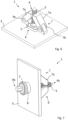
- Fig. 6 shows a schematic illustration in a perspective view of the fastening system of Fig. 5 focusing on a first side of the support structure 3.
- the support structure or frame 3 can comprise the first side and a second side opposite to the first side.
- the locking mechanism 6 can be arranged at the first side of the frame 3, for example.
- the sub-structure element 2 can be arranged at the second side.
- Each pivotable arm 7a comprises at least one protrusion for engaging with the recesses 5 of the locking bolt 4.
- the protrusion geometrically corresponds to the recess 5 such that they can engage with each other.
- Loads applying to the locking bolt 4 against the installation direction IN can be beared by the pivotable arms 7a, that means the stiff sections of the locking mechanism 6.
- the torsion spring 7b does not bear loads applying to the locking bolt 4 against the installation direction IN.
- the torsion spring 7b keeps the pivotable arm 7a in touch with the locking bolt 4, in particular with its recesses 5.
- Fig. 7 shows a schematic illustration in a perspective view of the fastening system of Fig. 5 focusing on the second side of the support structure 3.
- the bolt head 4b has a hexagon-shaped interface for unlocking/separating the bolt head 4b from the shaft 4a with a standard tool.
- Fig. 8 shows a schematic illustration in an explosion view of the fastening system of Fig. 5 .
- the bolt head 4b is releasable from the shaft 4a.
- Fig. 9 shows a schematic illustration in a cut view of a locking bolt 4.
- the locking bolt 4 comprises a shaft 4a and a bolt head 4b.
- the locking bolt 4 in Fig. 9 distinguishes from the locking bolt of Fig. 1 to 8 in that the shaft 4a has an inner thread, and the bolt head 4b has a corresponding outer thread.
- the skilled person can configure the releasable fixation of the shaft 4a and the bolt head 4b such that any load can be carried by the locking bolt 4.
- the skilled person can choose thread parameters, like a thread height, a pitch or a thread form, of the thread connection according to the load of the mechanical element 2.
- the bolt head 4b has a spherical shape.
- the shaft 4a comprises a plurality of recesses 5 and a cone-shaped front area.
- Fig. 10 shows a schematic illustration in a perspective view of a locking mechanism 6, which is mounted to a support structure 3.
- the locking mechanism 6 can be firmly bonded to the support structure 3, but is not limited thereto. Thereby, the locking mechanism 6 can be welded or adhered to the support structure 3.
- a bush 8 which is releasably connectable to the locking mechanism 6 and configured to guide the locking bolt 4 through the locking mechanism 6 is provided as it is illustrated in Fig. 10 .
- the bush 8 is screwed on the locking mechanism 6, wherein the locking mechanism 6 has an inner thread, and the bush 8 has a corresponding outer thread.
- Fig. 11 shows a flow chart for an attachment method M for fastening a fastening device for fastening a mechanical element 2 with a support structure 3.
- the attachment method M comprises the steps of mounting M1 and axially moving M2.
- the locking mechanism 6 is mounted to a support structure 3 at a first side of the support structure 3 facing in an installation direction IN.
- the first side can correspond to a back side of the support structure 3.
- a locking mechanism 6 can be mounted to the first side or back side, respectively, of the support structure 3, wherein the installation direction IN is directed from a front side or second side, respectively, of the support structure 3 to the backside.
- a locking bolt 4 of the fastening device is axially moved in the installation direction IN into the locking mechanism 6 of the fastening device, wherein the locking mechanism 6 comprises an elastically deformable element 7 for engaging with at least one recess 5 of the locking bolt, wherein the elastically deformable element 7 is configured to block a movement of the locking bolt 4 relative to the locking mechanism 6 along a longitudinal axis X against the installation direction IN and to not block the movement in the installation direction IN.
- Fig. 12 shows a flow chart for a detachment method S for unfastening a fastening device for fastening a mechanical element 2 with a support structure 3.
- the detachment method S comprises the steps of releasing S1 and axially moving S2.
- a bolt head 4b of a locking bolt 4 of the fastening device is released from a shaft 4a of the locking bolt 4.
- the shaft 4a is moved in an installation direction IN until the shaft 4a is released from a locking mechanism 6 of the fastening device.
- the bolt head 4b can be unscrewed from the shaft 4a. Furthermore, in the step of axially moving S2, the shaft 4a can be pulled or pushed in the installation direction IN.
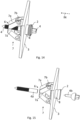
- Fig. 13 , 14 and 15 shows a schematic illustration of a fastening system 1.
- the fastening system comprises a fastening device 1 for fastening a mechanical element 2 with a support structure 3 with the features according to one of the fastening devices 1 of Fig. 1 to 10 .
- Fig. 13 illustrates the fastening system at the beginning of the attachment method M.
- the locking mechanism 6 is pre-assembled at the support structure 3, in particular by the bush 8.
- the locking bolt 4 is aligned with the locking mechanism 6 and the bush 8, respectively.
- the locking bolt 4 can be pushed in the installation direction IN to pass through the bush 8 and engage with the elastically deformable element 7.
- Fig. 14 illustrates the fastening system at the end of the attachment method M and at the beginning of the detachment method S.
- the locking bolt 4 is engaged with the locking mechanism 6.
- Fig. 15 the fastening system at the end of the detachment method S is illustrated.
- the bolt head 4b is released from the shaft 4a.
- the bolt head 4b is removed by unscrewing, for example.
- the shaft 4a thereby remains inside the locking mechanism 6.
- the shaft 4a can be removed from the locking mechanism 6 by pushing or pulling the shaft in the installation direction IN through the elastically deformable element 7.
Landscapes
- Engineering & Computer Science (AREA)
- General Engineering & Computer Science (AREA)
- Mechanical Engineering (AREA)
- Manufacturing & Machinery (AREA)
- Transportation (AREA)
- Aviation & Aerospace Engineering (AREA)
- Connection Of Plates (AREA)
Abstract
Description
- The invention relates to a fastening device for fastening a mechanical element with a support structure. The invention is furthermore concerned with fastening system containing such a fastening device. Further, the invention relates to an attachment method for fastening a fastening device for fastening a mechanical element with a support structure and a detachment method for unfastening a fastening device for fastening a mechanical element with a support structure.
- Modern vehicles such as aircraft and spacecraft are manufactured in sections, that are pre-assembled. For attaching further components to those sections attachment systems are needed. Especially in the field of aircraft and spacecraft a high precision in manufacturing is important.
- Further, the interior lining of aircraft is generally composed of individual elements, in which substantially plates or panels are placed adjacent to each other in a given framework or support structure. These plates or panels serve for example as cabin fitting elements.
- Nevertheless, each section and component or plate/panel of the aircraft has different manufacturing tolerances, which are to match during assembly processes.
- For example, document
DE 10 2019 118 494 A1 describes an assembly system which is particularly suitable for mounting components, in particular interior equipment components, in an aircraft and thereby fulfilling a tolerance compensation function. Furthermore, a method for mounting a component, in particular an aircraft interior equipment component, by means of such a mounting system, as well as a component arrangement mounted by means of such a mounting system is described. Furthermore, in documentDE 10 2020 116 253 A1 a fastener assembly comprising a fastener element having an electroactive polymer actuator is described. - Aspects of the invention may provide solutions for an alternative fastening device for fastening mechanical elements to support structures.
- According to the invention, this problem is solved in each case by the subject matters of the independent claims.
- According to a first aspect of the invention, a fastening device for fastening a mechanical element with a support structure is provided. In particular, a fastening device for fastening a cabin fitting element to a frame of an aircraft is provided. The fastening device comprises a locking bolt for mounting a mechanical element, wherein the locking bolt comprises at least one recess, which is located on at least a section of the shell surface of the locking bolt. Further, the fastening device comprises a locking mechanism, which is mountable to a support structure and comprises an elastically deformable element for engaging with the at least one recess of the locking bolt. The elastically deformable element is configured to block a movement of the locking bolt relative to the locking mechanism along a longitudinal axis against an installation direction and to not block the movement in an installation direction.
- According to a second aspect of the invention, a fastening system is provided. The fastening system comprises a support structure and a fastening device according to the first aspect of the invention, which is arranged at the support structure. Furthermore, the fastening system comprises a mechanical element, which is positively locked with the fastening device.
- According to a third aspect of the invention, an attachment method for fastening a fastening device for fastening a mechanical element with a support structure is provided. In particular, an attachment method for fastening a fastening device according to the first aspect of the invention is provided. The attachment method comprises axially moving a locking bolt of the fastening device in an installation direction into a locking mechanism of the fastening device, wherein the locking mechanism comprises an elastically deformable element for engaging with at least one recess of the locking bolt, wherein the elastically deformable element is configured to block a movement of the locking bolt relative to the locking mechanism along a longitudinal axis against the installation direction and to not block the movement in the installation direction.
- According to a fourth aspect of the invention, a detachment method for unfastening a fastening device for fastening a mechanical element with a support structure is provided. In particular, a detachment method for unfastening a fastening device according to the first aspect of the invention is provided. The detachment method comprises releasing a bolt head of a locking bolt of the fastening device from a shaft of the locking bolt and axially moving the shaft in a installation direction until the shaft is released from a locking mechanism of the fastening device.
- A fundamental concept of the invention is to attaching a blind locking fastening device or a continuous secondary structure interface, respectively, with a nearby stepless tolerance compensation for high load introduction on a limited space of the support structure. The fastening system is installed by pushing the locking bolt into the locking mechanism, wherein the locking mechanism is mounted at a predetermined position on the support structure. The shell surface of the locking bolt preferably corresponds to the inner shell of the locking mechanism. The locking bolt is configured to be slidable into the locking mechanism. The locking bolt passes through an opening of the mechanical element for having a positively-locking connection or form fit, respectively, wherein the bolt head has greater outer dimensions than the opening of the mechanical element such that the positively-locking connection or form fit, respectively, works between the bolt head and the locking mechanism. Thereby, the fastening device works according to a finger-trap principle. The fastening device only allows movement of the locking bolt in the installation direction.
- In the installation direction the locking bolt is slidable in relation to the locking mechanism in a locked position of the fastening device. In particular, the elastically deformable element engages positively-locking with the at least one recess. The elastically deformable element can be made of a material with elastic material properties or comprise at least one stiff section and at least one elastically deformable section. The elastically deformable section can be made of a material with elastic material properties, like rubber, or configured as a torsion spring or similar. When the locking bolt is housed in the locking mechanism, the elastically deformable element is at least sectionwise in contact with the locking bolt, in particular during sliding of the locking bolt in relation to the locking mechanism in the installation direction. The elastically deformable section brings the elastically deformable element into contact with the locking bolt and into engagement with the at least one recess of the locking bolt, when the locking bolt is inserted into the locking mechanism. When the locking bolt is under load the torsion spring or similar is not holding the locking bolt. Self-locking of the locking bolt works just by the finger-trap principle.
- The present invention is suitable for blind locking since the locking mechanism can be pre-assembled. With a pre-assembled locking mechanism the locking bolt can be mounted from one side only, wherein the locking bolt is fixed automatically when inserted into the locking mechanism.
- As a result, once the locking bolt is inserted into the locking mechanism the locking bolt can be mechanically connected to the locking mechanism. Therefore, for example, pulling back the locking bolt or against the installation direction, respectively, relative to the locking mechanism is blocked, when the elastically deformable element engages with the at least one recess.
- A particular advantage in the solution according to an aspect of the invention is that manufacturing efforts for assembling cabin fitting elements with the frame of the aircraft is reduced. Furthermore, the fastening device can be used for attaching a primary structure interface to the support structure with combining an inplane tolerance compensation of the manufacturing tolerances of the support structure. Therefore, further attachments, which are tolerance sensitive, can be attached to the primary structure interface. A guided installation of the mechanical element can lead to an automated tolerance compensation when mounted with the fastening device.
- Further advantages in the solution according to an aspect of the invention can be a smooth and continuous load introduction in the primary structure and/or a light and cheap tolerance compensation, in particular a stepless tolerance compensation on a short distance. Furthermore the present invention provides a master - slave principle for the adjustment of the secondary structure.
- Advantageous embodiments and further developments emerge from the description with reference to the figures.
- According to some aspects of the invention, the locking bolt comprises a shaft and a bolt head, which is releasably fixed on the shaft. In particular, the bolt head is screwed on the shaft. For example, the shaft or the bolt head has an inner thread, and the bolt head or the shaft, respectively, has a corresponding outer thread. The skilled person can configure the releasable fixation of the shaft and the bolt head such that any load can be carried by the locking bolt. For example, the skilled person can choose thread parameters, like a thread height, a pitch or a thread form, of the thread connection according to the load of the mechanical element.
- According to some further aspects of the invention, the bolt head comprises a spherical shape for rotary attachment of the mechanical element.
- According to some further aspects of the invention, the bolt head comprises an end extending away from the shaft of the locking bolt, wherein the end comprises at least one recess for engaging with an interface of a secondary structure. The at least one recess of the bolt head can be configured like the at least one recess of the locking bolt. Therefore, coupling of other attachments is enabled on the end of the bolt head when mounting these other attachments by means of the interface.
- According to some further aspects of the invention, the at least one recess is circumferential around the shell surface of the locking bolt or has a rectangular, a triangular or a curved cross-sectional shape. Furthermore, the at least one recess is circumferential around the shell surface of the locking bolt and has a rectangular, a triangular or a curved cross-sectional shape. For example, the at least one recess can be configured as a circumferential groove. The at least one recess can comprise a plurality of recesses, which are arranged between a bolt head and a front area of the locking bolt. In particular, each recess of the plurality of recesses has the same cross-sectional shape. Advantageously, the locking device can be mounted to support structures with variable thicknesses. The plurality of recesses can be configured as a tooth profile. Thus, tolerance compensation in the installation direction can be provided via the tooth profile.
- Further, the circumferential recess would not only apply to a cylindrical locking bolt, but also to a cuboid or a mixed form of locking bolts or to a rectangular, a square, a triangular or a curved, in particular a circular, cross-sectional shape of the shaft of the locking bolt. Thereby, the at least one recess extends in a peripheral direction around the shell surface of the locking bolt, irrespective of the shape of the locking bolt. Alternatively or additionally, the at least one recess of the locking bolt has a rectangular, a triangular, a curved or a combination thereof cross-sectional shape. The locking mechanism has a mutually adapted shape.
- According to some further aspects of the invention, the at least one recess substantially extends along the longitudinal axis and is arranged between a bolt head and a front area of the locking bolt. For example, the at least one recess can be configured as a longitudinal groove. The at least one recess can comprise a plurality of recesses, which are arranged around the shell surface of the locking bolt, in particular evenly distributed around the shell surface of the locking bolt. In particular, each recess of the plurality of recesses has the same cross-sectional shape. Thus, the fastening device can have a self-locking function, in particular prior to a locked position of the fastening device, since the locking bolt may continuously slide into the locking mechanism, wherein the self-locking function is present in an intermediate position, in which the elastically deformable element engages with at least one of the plurality of recesses.
- In some embodiments, the fastening device can comprise a plurality of recesses, wherein at least one recess of the plurality of recesses is circumferential around the shell surface of the locking bolt, and wherein at least one recess of the plurality of recesses substantially extends along the longitudinal axis and is arranged between a bolt head and a front area of the locking bolt.
- According to some further aspects of the invention, the elastically deformable element is pre-tensioned when in contact with the locking bolt or engaged with the at least one recess.
- According to some further aspects of the invention, the elastically deformable element comprises at least one pivotable arm, which is positioned at least sectionwise around the longitudinal axis and has a pivot axis substantially perpendicular to the longitudinal axis. The pivotable arm can be hinged to the locking mechanism by means of a torsion spring or similar. For example, the at least one arm can comprise two, three or four pivotable arms.
- Optionally, the fastening device may comprise an indicator for indicating a proper mounting of the fastening device. The indicator can be provided as a visual, tactile and/or acoustical indicator. One example for a visual indicator could be a colored line, which should be visible or not visible after the attachment of the fastening device.
- According to some further aspects of the invention, the fastening device further comprises a bush, which is releasably connectable to the locking mechanism and configured to guide the locking bolt through the locking mechanism. In particular, the bush is screwed on the locking mechanism. For example, the locking mechanism has an inner thread, and the bush has a corresponding outer thread. Alternatively or additionally, the locking mechanism can be firmly bonded to the support structure. Thereby, the locking mechanism can be welded or adhered to the support structure.
- Optionally, the locking bolt comprises a tapered front area for self-centering. In other words, the locking bolt has a cone shaped top for self-centering. Alternatively or additionally, the locking bolt can have a rectangular, a square, a triangular or a curved, in particular a circular, cross-sectional shape. For example, the shaft of the locking bolt has a rectangular, a square, a triangular or a curved, in particular a circular, cross-sectional shape.
- According to some aspects of the invention, the support structure is configured as a frame of an aircraft, and wherein the mechanical element is configured as a cabin fitting element. Thus, aircraft components are well-tested and mostly standardized.
- In some embodiments of the invention, the fastening device can be installed in an opening of the frame. Thus, a direct load transfer of the mechanical element into the support structure can be enabled. Furthermore, this installation can reduce the space needed for the fastening system.
- The support structure can comprise a first side and a second side opposite to the first side. The locking mechanism can be arranged at the first side of the support structure, for example. The mechanical element can be arranged at the second side.
- According to some further aspects of the invention, the attachment method further comprises mounting the locking mechanism to a support structure at a first side of the support structure facing in the installation direction. The first side can correspond to a back side of the support structure. Thus, the locking mechanism can be mounted to the first side or back side, respectively, of the support structure, wherein the installation direction is directed from a front side or second side, respectively, of the support structure to the backside.
- According to some further aspects of the invention, in the step of releasing of the detachment method, the bolt head is unscrewed from the shaft, and wherein, in the step of axially moving, the shaft is pulled or pushed in the installation direction.
- According to a further aspect of the invention, an aircraft comprising the fastening device or the fastening system may be provided.
- The present invention is explained more specifically below on the basis of the exemplary embodiments indicated in the schematic figures, in which:
- Fig. 1
- shows a schematic illustration of a fastening device for fastening a mechanical element with a support structure according to an embodiment of the invention;
- Fig. 2
- shows a schematic illustration of the fastening device of
Fig. 1 in an intermediate position; - Fig. 3
- shows a schematic illustration of the fastening device of
Fig. 1 in another intermediate position; - Fig. 4
- shows a schematic illustration of the fastening device of
Fig. 1 in a locked position; - Fig. 5
- shows a schematic illustration in a side view of a fastening system for fastening a mechanical element with a support structure according to a further embodiment of the invention;
- Fig. 6
- shows a schematic illustration in a perspective view of the fastening system of
Fig. 5 focusing on a first side of the support structure; - Fig. 7
- shows a schematic illustration in a perspective view of the fastening system of
Fig. 5 focusing on a second side of the support structure; - Fig. 8
- shows a schematic illustration in an explosion view of the fastening system of
Fig. 5 ; - Fig. 9
- shows a schematic illustration in a cut view of a locking bolt according to a further embodiment of the invention;
- Fig. 10
- shows a schematic illustration in a perspective view of a locking mechanism, which is mounted to a support structure;
- Fig. 11
- shows a flow chart for an attachment method for fastening a fastening device for fastening a mechanical element with a support structure according to a further embodiment of the invention;
- Fig. 12
- shows a flow chart for a detachment method for unfastening a fastening device for fastening a mechanical element with a support structure according to a further embodiment of the invention;
- Fig. 13
- shows a schematic illustration of a fastening system according to a further embodiment of the invention at the beginning of the attachment method;
- Fig. 14
- shows a schematic illustration of a fastening system according to a further embodiment of the invention at the end of the attachment method and at the beginning of the detachment method;
- Fig. 15
- shows a schematic illustration of a fastening system according to a further embodiment of the invention at the end of the detachment method.
- The accompanying figures are intended to convey a further understanding of the embodiments of the invention. They illustrate embodiments and are used in conjunction with the description to explain principles and concepts of the invention. Other embodiments and many of the cited advantages emerge in light of the drawings. The elements of the drawings are not necessarily shown to scale in relation to one another. Direction-indicating terminology such as for example "at the top", "at the bottom", "on the left", "on the right", "above", "below", "horizontally", "vertically", "at the front", "at the rear" and similar statements are merely used for explanatory purposes and do not serve to restrict the generality to specific configurations as shown in the figures.
- In the figures of the drawing, elements, features and components that are the same, have the same function and have the same effect are each provided with the same reference signs - unless explained otherwise.
- An elastically deformable element in the meaning of this application is an elastic object that stores mechanical energy. An elastically deformable element is typically made of spring steel, an elastomer or similar materials.
-
Fig. 1 shows a schematic illustration of afastening device 1 for fastening a mechanical element with asupport structure 3. Thefastening device 1 comprises alocking bolt 4 and alocking mechanism 6. - The
locking bolt 4 is configured for mounting a mechanical element, wherein thelocking bolt 4 comprises at least onerecess 5, which is located on at least a section of the shell surface of thelocking bolt 4. Here, the at least onerecess 5 comprises two recesses, which substantially extend along a longitudinal axis X. Thelocking bolt 4 has ashaft 4a and abolt head 4b. The shell surface of thelocking bolt 4 corresponds to the inner shell of thelocking mechanism 6. The tworecesses 5 are arranged between thebolt head 4b and a front area of thelocking bolt 4. For example, the tworecesses 5 are configured as a longitudinal groove. In particular, the tworecesses 5 have the same cross-sectional shape. - Furthermore, the locking
bolt 4 comprises a tapered front area. Thebolt head 4b comprises an end extending away from theshaft 4a of thelocking bolt 4, wherein the end comprises at least one recess for engaging with an interface of a secondary structure. Alternatively, the lockingbolt 4 can comprise arecess 5, which is circumferential around the shell surface of thelocking bolt 4. - The
locking mechanism 6 is mountable to asupport structure 3 and comprises an elasticallydeformable element 7 for engaging with the at least onerecess 5 of thelocking bolt 4. The elasticallydeformable element 7 is configured to block a movement of thelocking bolt 4 relative to thelocking mechanism 6 along the longitudinal axis X against an installation direction IN and to not block the movement in an installation direction IN. - The elastically
deformable element 7 exemplarily comprises twopivotable arms 7a, which are positioned at least sectionwise around the longitudinal axis X and have a pivot axis substantially perpendicular to the longitudinal axis X. The twopivotable arms 7a can be hinged to thelocking mechanism 6 by means of atorsion spring 7b or similar. - Here, the locking
bolt 4 comprises a tapered front area for self-centering. Furthermore, the lockingbolt 4 can have a square or a circular cross-sectional shape. In particular, theshaft 4a of thelocking bolt 4 has a square or a circular cross-sectional shape. -
Fig. 2 andFig. 3 each show a schematic illustration of thefastening device 1 ofFig. 1 in an intermediate position. - In the installation direction IN the
locking bolt 4 is slidable in relation to thelocking mechanism 6 in a locked position of thefastening device 1. When thelocking bolt 4 is housed in thelocking mechanism 6, the elasticallydeformable element 7 is at least sectionwise in contact with thelocking bolt 4, in particular during sliding of thelocking bolt 4 in relation to thelocking mechanism 6 in the installation direction IN, as it is specifically illustrated inFig. 3 . Thelocking mechanism 6 can be pre-assembled at thesupport structure 3. With apre-assembled locking mechanism 6 thelocking bolt 4 can be mounted from one side only, wherein thelocking bolt 4 is fixed automatically when inserted into thelocking mechanism 6. - Furthermore, the elastically
deformable element 7 is pre-tensioned when in contact with thelocking bolt 4 or engaged with the at least onerecess 5. -
Fig. 4 shows a schematic illustration of thefastening device 1 ofFig. 1 in a locked position. - In particular,
Fig. 4 shows thefastening device 1 in the locked position, in which thelocking bolt 4 reaches through a hole of thesupport structure 3 and in an insertion area of thelocking mechanism 6. In the locked position, the twopivotable arms 7a have a positively-locking connection or form fit, respectively, with the tworecesses 5 of thelocking bolt 4. -
Fig. 5 shows a schematic illustration in a side view of a fastening system for fastening amechanical element 2 with asupport structure 3. Specifically,Fig. 5 shows a fastening system comprising afastening device 1 for fastening a cabinfitting element 2 to a frame of anaircraft 3. - The exemplary fastening system comprises the
fastening device 1 and amechanical element 2 as well as asupport structure 3. Themechanical element 2 can be configured as a crown module sub-structure element, for example a cabin fitting element, with a hole at an end of the element. Thesupport structure 3 is a frame of an airport, wherein theframe 3 comprises a through-hole. Thefastening device 1 can be installed in the through-hole of theframe 3. - The
fastening device 1 is arranged at thesupport structure 3 and comprises alocking bolt 4, alocking mechanism 6 and abush 8. - The
locking bolt 4 is configured for mounting a mechanical element, wherein thelocking bolt 4 comprises at least onerecess 5, which is located on at least a section of the shell surface of thelocking bolt 4. Here, the at least onerecess 5 comprises a plurality of recesses, which are circumferential around the shell surface of thelocking bolt 4. For example, the plurality ofrecesses 5 is configured as circumferential grooves. In particular, each recess of the plurality ofrecesses 5 has the same cross-sectional shape. Thelocking bolt 4 comprises ashaft 4a and abolt head 4b, which is releasably fixed on theshaft 4a, in particular screwed on theshaft 4a. The shell surface of thelocking bolt 4 corresponds to the inner shell of thebush 8. The plurality of recesses are arranged between thebolt head 4b and a front area of thelocking bolt 4. - Here, the
bolt head 4b comprises a spherical shape for rotary attachment of thesub-structure element 2. Thesub-structure element 2 is positively locked with thefastening device 1. Furthermore, thebolt head 4b comprises an end extending away from theshaft 4a of thelocking bolt 4, wherein the end comprises at least one recess for engaging with an interface of a secondary structure. The at least one recess of thebolt head 4b can be configured like therecesses 5 of thelocking bolt 4. Furthermore, the lockingbolt 4 comprises a tapered front area. - The
locking mechanism 6 is mountable to asupport structure 3 and comprises an elasticallydeformable element 7 for engaging with the plurality ofrecesses 5 of thelocking bolt 4. The elasticallydeformable element 7 is configured to block a movement of thelocking bolt 4 relative to thelocking mechanism 6 along the longitudinal axis X against an installation direction IN and to not block the movement in an installation direction IN. - The elastically
deformable element 7 exemplarily comprises twopivotable arms 7a, which are positioned at least sectionwise around the longitudinal axis X and have a pivot axis substantially perpendicular to the longitudinal axis X. The twopivotable arms 7a are hinged to thelocking mechanism 6 by means of atorsion spring 7b. Hence, the elasticallydeformable element 7 comprises astiff section 7a corresponding to the pivotable arm and an elasticallydeformable section 7b. The elasticallydeformable section 7b is configured as a torsion spring. Here, the lockingbolt 4 also comprises a tapered front area for self-centering. - The
fastening device 1 mounts thesub-structure element 2 or the secondary structure, respectively, to theframe 3 by a positively-locking connection, as it is illustrated inFig. 5 . When in the locked position, thefastening device 1 can bear loads, which are charged on the fastening system in the longitudinal direction X and/or perpendicular to the longitudinal direction X. To compensate inaccuracies the hole of the crownmodule sub-structure element 2 through which thelocking bolt 4 passes, has a greater diameter than the shell surface of thelocking bolt 4, such that there is a gap between the shell surface and the crownmodule sub-structure element 2. Therefore, the crownmodule sub-structure element 2 can move in relation to thefastening device 1 perpendicular to the longitudinal axis X. - The
bush 8 is releasably connectable to thelocking mechanism 6 and configured to guide thelocking bolt 4 through thelocking mechanism 6. In particular, thebush 8 is screwed on thelocking mechanism 6. Therefore, thelocking mechanism 6 has an inner thread, and thebush 8 has a corresponding outer thread. Thebush 8 can be used for pre-assembling thelocking mechanism 6 at theframe 3. - The
exemplary fastening device 1 can be applied at variable frame thicknesses of theframe 3. -
Fig. 6 shows a schematic illustration in a perspective view of the fastening system ofFig. 5 focusing on a first side of thesupport structure 3. - The support structure or
frame 3 can comprise the first side and a second side opposite to the first side. Thelocking mechanism 6 can be arranged at the first side of theframe 3, for example. Thesub-structure element 2 can be arranged at the second side. - Each
pivotable arm 7a comprises at least one protrusion for engaging with therecesses 5 of thelocking bolt 4. Thus, the protrusion geometrically corresponds to therecess 5 such that they can engage with each other. - Loads applying to the
locking bolt 4 against the installation direction IN can be beared by thepivotable arms 7a, that means the stiff sections of thelocking mechanism 6. Thetorsion spring 7b does not bear loads applying to thelocking bolt 4 against the installation direction IN. Thetorsion spring 7b keeps thepivotable arm 7a in touch with thelocking bolt 4, in particular with itsrecesses 5. -
Fig. 7 shows a schematic illustration in a perspective view of the fastening system ofFig. 5 focusing on the second side of thesupport structure 3. - For example, the
bolt head 4b has a hexagon-shaped interface for unlocking/separating thebolt head 4b from theshaft 4a with a standard tool. -
Fig. 8 shows a schematic illustration in an explosion view of the fastening system ofFig. 5 . As it is illustrated inFig. 8 , thebolt head 4b is releasable from theshaft 4a. -
Fig. 9 shows a schematic illustration in a cut view of alocking bolt 4. - The
locking bolt 4 comprises ashaft 4a and abolt head 4b. Thelocking bolt 4 inFig. 9 distinguishes from the locking bolt ofFig. 1 to 8 in that theshaft 4a has an inner thread, and thebolt head 4b has a corresponding outer thread. The skilled person can configure the releasable fixation of theshaft 4a and thebolt head 4b such that any load can be carried by the lockingbolt 4. For example, the skilled person can choose thread parameters, like a thread height, a pitch or a thread form, of the thread connection according to the load of themechanical element 2. - Furthermore, the
bolt head 4b has a spherical shape. Theshaft 4a comprises a plurality ofrecesses 5 and a cone-shaped front area. -
Fig. 10 shows a schematic illustration in a perspective view of alocking mechanism 6, which is mounted to asupport structure 3. - For example, the
locking mechanism 6 can be firmly bonded to thesupport structure 3, but is not limited thereto. Thereby, thelocking mechanism 6 can be welded or adhered to thesupport structure 3. - Alternatively or additionally, a
bush 8, which is releasably connectable to thelocking mechanism 6 and configured to guide thelocking bolt 4 through thelocking mechanism 6 is provided as it is illustrated inFig. 10 . In particular, thebush 8 is screwed on thelocking mechanism 6, wherein thelocking mechanism 6 has an inner thread, and thebush 8 has a corresponding outer thread. -
Fig. 11 shows a flow chart for an attachment method M for fastening a fastening device for fastening amechanical element 2 with asupport structure 3. - The attachment method M comprises the steps of mounting M1 and axially moving M2.
- In the step of mounting M1, the
locking mechanism 6 is mounted to asupport structure 3 at a first side of thesupport structure 3 facing in an installation direction IN. The first side can correspond to a back side of thesupport structure 3. Thus, alocking mechanism 6 can be mounted to the first side or back side, respectively, of thesupport structure 3, wherein the installation direction IN is directed from a front side or second side, respectively, of thesupport structure 3 to the backside. - In the step of axially moving M2, a
locking bolt 4 of the fastening device is axially moved in the installation direction IN into thelocking mechanism 6 of the fastening device, wherein thelocking mechanism 6 comprises an elasticallydeformable element 7 for engaging with at least onerecess 5 of the locking bolt, wherein the elasticallydeformable element 7 is configured to block a movement of thelocking bolt 4 relative to thelocking mechanism 6 along a longitudinal axis X against the installation direction IN and to not block the movement in the installation direction IN. -
Fig. 12 shows a flow chart for a detachment method S for unfastening a fastening device for fastening amechanical element 2 with asupport structure 3. - The detachment method S comprises the steps of releasing S1 and axially moving S2.
- In the step of releasing S1, a
bolt head 4b of alocking bolt 4 of the fastening device is released from ashaft 4a of thelocking bolt 4. - In the step of axially moving S2, the
shaft 4a is moved in an installation direction IN until theshaft 4a is released from alocking mechanism 6 of the fastening device. - In particular, in the step of releasing S1, the
bolt head 4b can be unscrewed from theshaft 4a. Furthermore, in the step of axially moving S2, theshaft 4a can be pulled or pushed in the installation direction IN. -
Fig. 13 ,14 and 15 shows a schematic illustration of afastening system 1. The fastening system comprises afastening device 1 for fastening amechanical element 2 with asupport structure 3 with the features according to one of thefastening devices 1 ofFig. 1 to 10 . - Specifically,
Fig. 13 illustrates the fastening system at the beginning of the attachment method M. Here, thelocking mechanism 6 is pre-assembled at thesupport structure 3, in particular by thebush 8. Thelocking bolt 4 is aligned with thelocking mechanism 6 and thebush 8, respectively. Hence, the lockingbolt 4 can be pushed in the installation direction IN to pass through thebush 8 and engage with the elasticallydeformable element 7. - Moreover,
Fig. 14 illustrates the fastening system at the end of the attachment method M and at the beginning of the detachment method S. Thelocking bolt 4 is engaged with thelocking mechanism 6. - In
Fig. 15 , the fastening system at the end of the detachment method S is illustrated. Thebolt head 4b is released from theshaft 4a. Thebolt head 4b is removed by unscrewing, for example. Theshaft 4a thereby remains inside thelocking mechanism 6. Then, theshaft 4a can be removed from thelocking mechanism 6 by pushing or pulling the shaft in the installation direction IN through the elasticallydeformable element 7. - In the detailed description above, various features have been combined in one or more examples in order to improve the rigorousness of the illustration. However, it should be clear in this case that the above description is of merely illustrative but in no way restrictive nature. It serves to cover all alternatives, modifications and equivalents of the various features and exemplary embodiments. Many other examples will be immediately and directly clear to a person skilled in the art on the basis of his knowledge in the art in consideration of the above description.
- The exemplary embodiments have been chosen and described in order to be able to present the principles underlying the invention and their application possibilities in practice in the best possible way. As a result, those skilled in the art can optimally modify and utilize the invention and its various exemplary embodiments with regard to the intended purpose of use. In the claims and the description, the terms "including" and "having" are used as neutral linguistic concepts for the corresponding terms "comprising". Furthermore, use of the terms "a", "an" and "one" shall not in principle exclude the plurality of features and components described in this way.
- While at least one exemplary embodiment of the present invention(s) is disclosed herein, it should be understood that modifications, substitutions and alternatives may be apparent to one of ordinary skill in the art and can be made without departing from the scope of this disclosure. This disclosure is intended to cover any adaptations or variations of the exemplary embodiment(s). In addition, in this disclosure, the terms "comprise" or "comprising" do not exclude other elements or steps, the terms "a" or "one" do not exclude a plural number, and the term "or" means either or both. Furthermore, characteristics or steps which have been described may also be used in combination with other characteristics or steps and in any order unless the disclosure or context suggests otherwise. This disclosure hereby incorporates by reference the complete disclosure of any patent or application from which it claims benefit or priority.
-
- 1
- fastening device
- 2
- mechanical element
- 3
- support structure
- 4
- locking bolt
- 4a
- shaft
- 4b
- bolt head
- 5
- at least one recess
- 6
- locking mechanism
- 7
- elastically deformable element
- 7a
- stiff section
- 7b
- elastically deformable section
- 8
- bush
- X
- longitudinal axis
- IN
- installation direction
- M
- attachment method
- M1
- mounting
- M2
- axially moving
- S
- detachment method
- S1
- releasing
- S2
- axially moving
Claims (15)
- Fastening device (1) for fastening a mechanical element (2) with a support structure (3), in particular for fastening a cabin fitting element to a frame of an aircraft, the fastening device (1) comprising:a locking bolt (4) for mounting a mechanical element (2), wherein the locking bolt (4) comprises at least one recess (5), which is located on at least a section of the shell surface of the locking bolt (4); anda locking mechanism (6), which is mountable to a support structure (3) and comprises an elastically deformable element (7) for engaging with the at least one recess (5) of the locking bolt (4), wherein the elastically deformable element (7) is configured to block a movement of the locking bolt (4) relative to the locking mechanism (6) along a longitudinal axis (X) against an installation direction (IN) and to not block the movement in an installation direction (IN).
- Fastening device (1) according to claim 1, wherein the locking bolt (4) comprises a shaft (4a) and a bolt head (4b), which is releasably fixed on the shaft (4a), in particular screwed on the shaft (4a).
- Fastening device (1) according to claim 2, wherein the bolt head (4b) comprises a spherical shape for rotary attachment of the mechanical element (2).
- Fastening device (1) according to claim 2 or 3, wherein the bolt head (4b) comprises an end extending away from the shaft (4a) of the locking bolt (4), wherein the end comprises at least one recess for engaging with an interface of a secondary structure.
- Fastening device (1) according to one of the preceding claims, wherein the at least one recess (5) is circumferential around the shell surface of the locking bolt (4) and/or has a rectangular, a triangular or a curved cross-sectional shape.
- Fastening device (1) according to one of the claims 1 to 4, wherein the at least one recess (5) substantially extends along the longitudinal axis (X) and is arranged between a bolt head (4b) and a front area of the locking bolt (4).
- Fastening device (1) according to one of the preceding claims, wherein the elastically deformable element is pre-tensioned when in contact with the locking bolt or engaged with the at least one recess.
- Fastening device (1) according to one of the preceding claims, wherein the elastically deformable element (7) comprises at least one pivotable arm (7a), which is positioned at least sectionwise around the longitudinal axis (X) and has a pivot axis substantially perpendicular to the longitudinal axis (X).
- Fastening device (1) according to one of the preceding claims, further comprising a bush (8), which is releasably connectable to the locking mechanism 6 and configured to guide the locking bolt 4 through the locking mechanism 6.
- Fastening system, comprising:a support structure (3);a fastening device (1) according to one of the preceding claims, which is arranged at the support structure (3); anda mechanical element (2), which is positively locked with the fastening device (1).
- Fastening system according to claim 10, wherein the support structure (3) is configured as a frame of an aircraft, and wherein the mechanical element (2) is configured as a cabin fitting element.
- Attachment method (M) for fastening a fastening device for fastening a mechanical element (2) with a support structure (3), in particular a fastening device (1) according to one of the claims 1 to 9, the method (M) comprising:
axially moving (M2) a locking bolt (4) of the fastening device in an installation direction (IN) into a locking mechanism (6) of the fastening device, wherein the locking mechanism (6) comprises an elastically deformable element (7) for engaging with at least one recess (5) of the locking bolt, wherein the elastically deformable element (7) is configured to block a movement of the locking bolt (4) relative to the locking mechanism (6) along a longitudinal axis (X) against the installation direction (IN) and to not block the movement in the installation direction (IN). - Attachment method (M) according to claim 12, further comprising mounting (M1) the locking mechanism (6) to a support structure (3) at a first side of the support structure (3) facing in the installation direction (IN).
- Detachment method (S) for unfastening a fastening device for fastening a mechanical element (2) with a support structure (3), in particular a fastening device (1) according to one of the claims 1 to 9, the method (S) comprising :releasing (S1) a bolt head (4b) of a locking bolt (4) of the fastening device from a shaft (4a) of the locking bolt (4); andaxially moving (S2) the shaft (4a) in an installation direction (IN) until the shaft (4a) is released from a locking mechanism (6) of the fastening device.
- Detachment method (S) according to claim 14, wherein in releasing (S1) the bolt head (4b) is unscrewed from the shaft (4a), and wherein in axially moving (S2) the shaft (4a) is pulled or pushed in the installation direction (IN).
Priority Applications (1)
| Application Number | Priority Date | Filing Date | Title |
|---|---|---|---|
| EP23200355.8A EP4530483A1 (en) | 2023-09-28 | 2023-09-28 | Fastening device for fastening a mechanical element with a support structure, fastening system, attachment method as well as detachment method |
Applications Claiming Priority (1)
| Application Number | Priority Date | Filing Date | Title |
|---|---|---|---|
| EP23200355.8A EP4530483A1 (en) | 2023-09-28 | 2023-09-28 | Fastening device for fastening a mechanical element with a support structure, fastening system, attachment method as well as detachment method |
Publications (1)
| Publication Number | Publication Date |
|---|---|
| EP4530483A1 true EP4530483A1 (en) | 2025-04-02 |
Family
ID=88236634
Family Applications (1)
| Application Number | Title | Priority Date | Filing Date |
|---|---|---|---|
| EP23200355.8A Pending EP4530483A1 (en) | 2023-09-28 | 2023-09-28 | Fastening device for fastening a mechanical element with a support structure, fastening system, attachment method as well as detachment method |
Country Status (1)
| Country | Link |
|---|---|
| EP (1) | EP4530483A1 (en) |
Citations (8)
| Publication number | Priority date | Publication date | Assignee | Title |
|---|---|---|---|---|
| US2416873A (en) * | 1944-06-24 | 1947-03-04 | Alex M Gorfin | Cowling fastener |
| EP0229885A2 (en) * | 1985-12-18 | 1987-07-29 | Valeo Neiman | Connecting device for vehicle door handle |
| DE3842609A1 (en) * | 1988-12-17 | 1990-06-21 | Stabilus Gmbh | Ball-headed pivot of a ball-and-socket joint |
| EP0791759A1 (en) * | 1996-02-24 | 1997-08-27 | Schwarz Verbindungs-Systeme GmbH | Quick-release fastener |
| EP2738401A2 (en) * | 2012-11-29 | 2014-06-04 | Hubert Fritz | Fast mounting element |
| DE102019118494A1 (en) | 2019-07-09 | 2021-01-14 | Airbus Operations Gmbh | Assembly system, method for assembling a component, component arrangement and aircraft |
| US20210348632A1 (en) * | 2020-05-05 | 2021-11-11 | Premium Aerotec Gmbh | Tolerance-Compensating Fastening Arrangement For Fastening A Component To A Structure |
| DE102020116253A1 (en) | 2020-06-19 | 2021-12-23 | Airbus Operations Gmbh | Fastening arrangement with a fastening element with an electroactive polymer actuator |
-
2023
- 2023-09-28 EP EP23200355.8A patent/EP4530483A1/en active Pending
Patent Citations (8)
| Publication number | Priority date | Publication date | Assignee | Title |
|---|---|---|---|---|
| US2416873A (en) * | 1944-06-24 | 1947-03-04 | Alex M Gorfin | Cowling fastener |
| EP0229885A2 (en) * | 1985-12-18 | 1987-07-29 | Valeo Neiman | Connecting device for vehicle door handle |
| DE3842609A1 (en) * | 1988-12-17 | 1990-06-21 | Stabilus Gmbh | Ball-headed pivot of a ball-and-socket joint |
| EP0791759A1 (en) * | 1996-02-24 | 1997-08-27 | Schwarz Verbindungs-Systeme GmbH | Quick-release fastener |
| EP2738401A2 (en) * | 2012-11-29 | 2014-06-04 | Hubert Fritz | Fast mounting element |
| DE102019118494A1 (en) | 2019-07-09 | 2021-01-14 | Airbus Operations Gmbh | Assembly system, method for assembling a component, component arrangement and aircraft |
| US20210348632A1 (en) * | 2020-05-05 | 2021-11-11 | Premium Aerotec Gmbh | Tolerance-Compensating Fastening Arrangement For Fastening A Component To A Structure |
| DE102020116253A1 (en) | 2020-06-19 | 2021-12-23 | Airbus Operations Gmbh | Fastening arrangement with a fastening element with an electroactive polymer actuator |
Similar Documents
| Publication | Publication Date | Title |
|---|---|---|
| US6571515B1 (en) | Motor vehicle door having a module carrier for mounting a window lift to the door | |
| JP4679568B2 (en) | Support device for galley | |
| US9243657B2 (en) | Fastener retaining device | |
| US20190329907A1 (en) | Fastening system for fastening built-in elements in a cabin of a vehicle | |
| EP2554471B1 (en) | Loads interface, particularly a loads interface of an aircraft structure | |
| US20220220791A1 (en) | Glazing unit with two-part window bracket and method for producing said glazing unit | |
| US7922413B2 (en) | Connecting element | |
| US20100074673A1 (en) | Snap-and-click hatrack fastener | |
| US12187407B2 (en) | Aircraft including a fuselage and a panel removably fixed to the fuselage with the aid of fixing means | |
| US20130139374A1 (en) | Attachment arrangement, a connecting device, and also a method | |
| EP2465774A1 (en) | Adapter and method for installing monuments | |
| US10625861B2 (en) | Aircraft installation arrangement and installation system for mounting an overhead luggage compartment | |
| EP3266705B1 (en) | Interior component carrier system and method for mounting an aircraft interior component carrier system | |
| EP2690014B1 (en) | Sealing device for galley hard point | |
| EP3476716B1 (en) | Access cover | |
| EP4343159B1 (en) | Fastening device for fastening a mechanical element with a support structure as well as fastening system | |
| US20240166362A1 (en) | Aircraft removable equipment fitting device | |
| CN101456345A (en) | Engine mounting assembly and method for fastening an engine to a vehicle body | |
| EP2730497B1 (en) | Aircraft window arrangement | |
| EP4372876B1 (en) | Fastening device for a battery pack, battery pack and method | |
| EP4527737A1 (en) | Aircraft monument attachment apparatus | |
| US20260070648A1 (en) | Fastening device for connecting to a holding device by interlocking and frictional engagement, fastening system for a supporting structure of a means of transport, in particular for a stiffening profile of an aircraft, and aircraft | |
| US12589855B2 (en) | Window mounting structure for snap and click mounting of a window assembly of an aircraft | |
| EP4389591B1 (en) | Hatch locking device, air- or spacecraft hatch and air- or spacecraft | |
| US20250026465A1 (en) | Assembly comprising at least one connecting element and at least two contact surfaces provided with asperities, aircraft comprising at least one such assembly |
Legal Events
| Date | Code | Title | Description |
|---|---|---|---|
| PUAI | Public reference made under article 153(3) epc to a published international application that has entered the european phase |
Free format text: ORIGINAL CODE: 0009012 |
|
| STAA | Information on the status of an ep patent application or granted ep patent |
Free format text: STATUS: THE APPLICATION HAS BEEN PUBLISHED |
|
| AK | Designated contracting states |
Kind code of ref document: A1 Designated state(s): AL AT BE BG CH CY CZ DE DK EE ES FI FR GB GR HR HU IE IS IT LI LT LU LV MC ME MK MT NL NO PL PT RO RS SE SI SK SM TR |
|
| STAA | Information on the status of an ep patent application or granted ep patent |
Free format text: STATUS: REQUEST FOR EXAMINATION WAS MADE |
|
| 17P | Request for examination filed |
Effective date: 20250919 |
|
| GRAP | Despatch of communication of intention to grant a patent |
Free format text: ORIGINAL CODE: EPIDOSNIGR1 |
|
| STAA | Information on the status of an ep patent application or granted ep patent |
Free format text: STATUS: GRANT OF PATENT IS INTENDED |