EP4530477A1 - Volute, fan and air conditioner - Google Patents
Volute, fan and air conditioner Download PDFInfo
- Publication number
- EP4530477A1 EP4530477A1 EP23939398.6A EP23939398A EP4530477A1 EP 4530477 A1 EP4530477 A1 EP 4530477A1 EP 23939398 A EP23939398 A EP 23939398A EP 4530477 A1 EP4530477 A1 EP 4530477A1
- Authority
- EP
- European Patent Office
- Prior art keywords
- air duct
- volute
- fan blade
- molded line
- convex hull
- Prior art date
- Legal status (The legal status is an assumption and is not a legal conclusion. Google has not performed a legal analysis and makes no representation as to the accuracy of the status listed.)
- Pending
Links
Images


Classifications
-
- F—MECHANICAL ENGINEERING; LIGHTING; HEATING; WEAPONS; BLASTING
- F04—POSITIVE - DISPLACEMENT MACHINES FOR LIQUIDS; PUMPS FOR LIQUIDS OR ELASTIC FLUIDS
- F04D—NON-POSITIVE-DISPLACEMENT PUMPS
- F04D29/00—Details, component parts, or accessories
- F04D29/40—Casings; Connections of working fluid
- F04D29/42—Casings; Connections of working fluid for radial or helico-centrifugal pumps
- F04D29/4206—Casings; Connections of working fluid for radial or helico-centrifugal pumps especially adapted for elastic fluid pumps
- F04D29/4226—Fan casings
- F04D29/4233—Fan casings with volutes extending mainly in axial or radially inward direction
-
- F—MECHANICAL ENGINEERING; LIGHTING; HEATING; WEAPONS; BLASTING
- F04—POSITIVE - DISPLACEMENT MACHINES FOR LIQUIDS; PUMPS FOR LIQUIDS OR ELASTIC FLUIDS
- F04D—NON-POSITIVE-DISPLACEMENT PUMPS
- F04D29/00—Details, component parts, or accessories
- F04D29/40—Casings; Connections of working fluid
- F04D29/42—Casings; Connections of working fluid for radial or helico-centrifugal pumps
- F04D29/4206—Casings; Connections of working fluid for radial or helico-centrifugal pumps especially adapted for elastic fluid pumps
- F04D29/422—Discharge tongues
-
- F—MECHANICAL ENGINEERING; LIGHTING; HEATING; WEAPONS; BLASTING
- F04—POSITIVE - DISPLACEMENT MACHINES FOR LIQUIDS; PUMPS FOR LIQUIDS OR ELASTIC FLUIDS
- F04D—NON-POSITIVE-DISPLACEMENT PUMPS
- F04D25/00—Pumping installations or systems
- F04D25/02—Units comprising pumps and their driving means
- F04D25/08—Units comprising pumps and their driving means the working fluid being air, e.g. for ventilation
-
- F—MECHANICAL ENGINEERING; LIGHTING; HEATING; WEAPONS; BLASTING
- F04—POSITIVE - DISPLACEMENT MACHINES FOR LIQUIDS; PUMPS FOR LIQUIDS OR ELASTIC FLUIDS
- F04D—NON-POSITIVE-DISPLACEMENT PUMPS
- F04D29/00—Details, component parts, or accessories
- F04D29/26—Rotors specially for elastic fluids
- F04D29/28—Rotors specially for elastic fluids for centrifugal or helico-centrifugal pumps for radial-flow or helico-centrifugal pumps
- F04D29/30—Vanes
-
- F—MECHANICAL ENGINEERING; LIGHTING; HEATING; WEAPONS; BLASTING
- F04—POSITIVE - DISPLACEMENT MACHINES FOR LIQUIDS; PUMPS FOR LIQUIDS OR ELASTIC FLUIDS
- F04D—NON-POSITIVE-DISPLACEMENT PUMPS
- F04D29/00—Details, component parts, or accessories
- F04D29/40—Casings; Connections of working fluid
- F04D29/42—Casings; Connections of working fluid for radial or helico-centrifugal pumps
- F04D29/4206—Casings; Connections of working fluid for radial or helico-centrifugal pumps especially adapted for elastic fluid pumps
- F04D29/4226—Fan casings
- F04D29/4246—Fan casings comprising more than one outlet
-
- F—MECHANICAL ENGINEERING; LIGHTING; HEATING; WEAPONS; BLASTING
- F04—POSITIVE - DISPLACEMENT MACHINES FOR LIQUIDS; PUMPS FOR LIQUIDS OR ELASTIC FLUIDS
- F04D—NON-POSITIVE-DISPLACEMENT PUMPS
- F04D29/00—Details, component parts, or accessories
- F04D29/40—Casings; Connections of working fluid
- F04D29/42—Casings; Connections of working fluid for radial or helico-centrifugal pumps
- F04D29/44—Fluid-guiding means, e.g. diffusers
- F04D29/441—Fluid-guiding means, e.g. diffusers especially adapted for elastic fluid pumps
-
- F—MECHANICAL ENGINEERING; LIGHTING; HEATING; WEAPONS; BLASTING
- F04—POSITIVE - DISPLACEMENT MACHINES FOR LIQUIDS; PUMPS FOR LIQUIDS OR ELASTIC FLUIDS
- F04D—NON-POSITIVE-DISPLACEMENT PUMPS
- F04D29/00—Details, component parts, or accessories
- F04D29/66—Combating cavitation, whirls, noise, vibration or the like; Balancing
-
- F—MECHANICAL ENGINEERING; LIGHTING; HEATING; WEAPONS; BLASTING
- F05—INDEXING SCHEMES RELATING TO ENGINES OR PUMPS IN VARIOUS SUBCLASSES OF CLASSES F01-F04
- F05D—INDEXING SCHEME FOR ASPECTS RELATING TO NON-POSITIVE-DISPLACEMENT MACHINES OR ENGINES, GAS-TURBINES OR JET-PROPULSION PLANTS
- F05D2250/00—Geometry
- F05D2250/20—Three-dimensional
- F05D2250/29—Three-dimensional machined; miscellaneous
- F05D2250/291—Three-dimensional machined; miscellaneous hollowed
-
- F—MECHANICAL ENGINEERING; LIGHTING; HEATING; WEAPONS; BLASTING
- F05—INDEXING SCHEMES RELATING TO ENGINES OR PUMPS IN VARIOUS SUBCLASSES OF CLASSES F01-F04
- F05D—INDEXING SCHEME FOR ASPECTS RELATING TO NON-POSITIVE-DISPLACEMENT MACHINES OR ENGINES, GAS-TURBINES OR JET-PROPULSION PLANTS
- F05D2250/00—Geometry
- F05D2250/50—Inlet or outlet
- F05D2250/52—Outlet
-
- F—MECHANICAL ENGINEERING; LIGHTING; HEATING; WEAPONS; BLASTING
- F24—HEATING; RANGES; VENTILATING
- F24F—AIR-CONDITIONING; AIR-HUMIDIFICATION; VENTILATION; USE OF AIR CURRENTS FOR SCREENING
- F24F1/00—Room units for air-conditioning, e.g. separate or self-contained units or units receiving primary air from a central station
- F24F1/0007—Indoor units, e.g. fan coil units
- F24F1/0018—Indoor units, e.g. fan coil units characterised by fans
- F24F1/0022—Centrifugal or radial fans
Definitions
- the present invention relates to the technical field of air conditioners, specifically to a volute, a fan and an air conditioner.
- the distributed air supply technology has gained higher recognition in the air conditioner market.
- the technology is mainly applied to high-end products, which results in insufficient market competitiveness.
- the high-pressure air flow at a double-suction volute air outlet is easy to return, which may easily cause vortex loss and return loss in the volute, resulting in reduced fan efficiency and discontinuous aerodynamic noise at the volute outlet, thereby causing poor sound quality of an air conditioner.
- the main purpose of the present invention is to provide a volute, a fan and an air conditioner to solve the problems of relatively low fan efficiency of a single-centrifugal double-suction fan and discontinuous aerodynamic noise at a volute outlet in the prior art.
- a volute including: a volute main body, wherein the volute main body includes a fan blade mounting part used for mounting a fan blade assembly and two air duct parts disposed on two sides of the fan blade mounting part at an interval along a first direction and in communication with the fan blade mounting part, and the fan blade mounting part is used for mounting the fan blade assembly; a first air duct molded line and a second air duct molded line are respectively formed between two opposite sides, disposed at an interval along a second direction, of each air duct part and the fan blade mounting part, a joint between a side, close to the first air duct molded line, of each of the two air duct parts and the fan blade mounting part is disposed in a streamline mode, and a volute tongue is disposed at the joint between a side, close to the second air duct molded line, of each of the two air duct parts and the fan blade mounting part; and convex hulls protrud
- the convex hull includes: an upper surface, the upper surface and the air duct part being disposed at an interval; a first side surface and a second side surface, the first side surface and the second side surface being respectively located on two opposite sides, disposed at an interval along an extension direction of the air duct part, of the upper surface, the first side surface being located on a side, away from the fan blade mounting part, of the upper surface, and the second side surface being located on a side, close to the fan blade mounting part, of the upper surface; and a third side surface and a fourth side surface, the third side surface and the fourth side surface being respectively located on two opposite sides, disposed at an interval along a direction perpendicular to the extension direction of the air duct part, of the upper surface, the third side surface being located on a side, close to the first air duct molded line, of the upper surface, and the fourth side surface being located on a side, close to the second air duct molded line, of the upper surface, wherein the upper surface is connected with an outer surface of
- an inner wall surface of the side, close to the volute tongue, of the convex hull is connected with an inner wall surface of the side, close to the volute tongue, of the volute main body.
- a minimum distance between the convex hull and the volute tongue is c, wherein 0 ⁇ c ⁇ 5 mm; a width of the convex hull in a extension direction of the air duct part is a, wherein 65 mm ⁇ a ⁇ 75 mm; a length of the convex hull in a direction perpendicular to the extension direction of the air duct part is b, wherein 65 mm ⁇ b ⁇ 75 mm; a the height of the convex hull in a direction parallel to the rotating axis of the fan blade assembly is h, wherein 8 mm ⁇ h ⁇ 12 mm.
- an included angle between the upper surface and the first side surface is ⁇ , wherein 15° ⁇ 25°; an included angle between the upper surface and the second side surface is ⁇ , wherein 30° ⁇ 40°; and an included angle between the upper surface and the fourth side surface is ⁇ , wherein 40° ⁇ 50°.
- an inner wall surface of the side, away from the volute tongue, of the convex hull is connected with an inner wall surface of a side, away from the volute tongue, of the volute main body.
- a minimum distance between the convex hull and the volute tongue is c, wherein 0 ⁇ c ⁇ 5 mm; a width of the convex hull in a extension direction of the air duct part is a, wherein 65 mm ⁇ a ⁇ 75 mm; a length of the convex hull in a direction perpendicular to the extension direction of the air duct part is b, wherein 85 mm ⁇ b ⁇ 95 mm; and a height of the convex hull in a direction parallel to the rotating axis of the fan blade assembly is h, wherein 8 mm ⁇ h ⁇ 12 mm.
- a gap is respectively reserved between two inner wall surfaces, close to the first air duct molded line and the second air duct molded line respectively, of the convex hull and an inner wall surface of the volute main body.
- a minimum distance between the convex hull and the volute tongue is c, wherein 0 ⁇ c ⁇ 5 mm; a width of the convex hull in a extension direction of the air duct part is a, wherein 65 mm ⁇ a ⁇ 75 mm; a length of the convex hull in a direction perpendicular to the extension direction of the air duct part is b, wherein 50 mm ⁇ b ⁇ 60 mm; and a height of the convex hull in a direction parallel to the rotating axis of the fan blade assembly is h, wherein 8 mm ⁇ h ⁇ 12 mm.
- a fan including the above volute and the fan blade assembly disposed in the volute.
- an air conditioner including the above fan.
- the volute of the present invention includes: a volute main body, wherein the volute main body includes a fan blade mounting part used for mounting a fan blade assembly and two air duct parts disposed on two sides of the fan blade mounting part at an interval along a first direction and in communication with the fan blade mounting part, and the fan blade mounting part is used for mounting the fan blade assembly; a first air duct molded line and a second air duct molded line are respectively formed between two opposite sides, disposed at an interval along a second direction, of each air duct part and the fan blade mounting part, a joint between a side, close to the first air duct molded line, of each of the two air duct parts and the fan blade mounting part is disposed in a streamline mode, and a volute tongue is disposed at the joint between a side, close to the second air duct molded line, of each of the two air duct parts and the fan blade mounting part; and convex hulls protruding towards a direction away from a
- the air volume of a double-suction single-centrifugal fan is increased, the phenomenon of uneven air flow velocity distribution in an air duct is improved, the aerodynamic noise of the double-suction centrifugal fan is reduced, and the working performance of the centrifugal fan is increased.
- the flow direction of the outlet air flow is adjusted, the phenomenon of air flow return can be effectively suppressed in different air sensing modes, vortices in the air duct are effectively reduced, the air flow loss is reduced, the noise problems such as outlet air duct surge and discontinuous air flow are improved, the comfort experience of users is increased, and the problems of relatively low fan efficiency of a single-centrifugal double-suction fan and discontinuous aerodynamic noise at a volute outlet in the art known to inventors are solved.
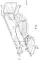
- the present invention provides a volute, including: a volute main body 1, wherein the volute main body 1 includes a fan blade mounting part 3 used for mounting a fan blade assembly 2 and two air duct parts 4 disposed on two sides of the fan blade mounting part 3 at an interval along a first direction and in communication with the fan blade mounting part 3, and the fan blade mounting part 3 is used for mounting the fan blade assembly 2; a first air duct molded line 5 and a second air duct molded line 6 are respectively formed between two opposite sides, disposed at an interval along a second direction, of each air duct part 4 and the fan blade mounting part 3, a joint between a side, close to the first air duct molded line 5, of each of the two air duct parts 4 and the fan blade mounting part 3 is disposed in a streamline mode, and a volute tongue 7 is disposed at the joint between a side, close to the second air duct molded line 6, of each of the two air duct parts 4 and the fan blade mounting part
- the air volume of a double-suction single-centrifugal fan is increased, the phenomenon of uneven air flow velocity distribution in an air duct is improved, the aerodynamic noise of the double-suction centrifugal fan is reduced, and the working performance of the centrifugal fan is increased.
- the flow direction of the outlet air flow is adjusted, the phenomenon of air flow return can be effectively suppressed in different air sensing modes, vortices in the air duct are effectively reduced, the air flow loss is reduced, the noise problems such as outlet air duct surge and discontinuous air flow are improved, the comfort experience of users is increased, and the problems of relatively low fan efficiency of a single-centrifugal double-suction fan and discontinuous aerodynamic noise at a volute outlet in the prior art are solved.
- the convex hull 8 includes: an upper surface 81, the upper surface 81 and the air duct part 4 being disposed at an interval; a first side surface 82 and a second side surface 83, the first side surface 82 and the second side surface 83 being respectively located on two opposite sides, disposed at an interval along an extension direction of the air duct part 4, of the upper surface 81, the first side surface 82 being located on a side, away from the fan blade mounting part 3, of the upper surface 81, and the second side surface 83 being located on a side, close to the fan blade mounting part 3, of the upper surface 81; and a third side surface 84 and a fourth side surface 85, the third side surface 84 and the fourth side surface 85 being respectively located on two opposite sides, disposed at an interval along a direction perpendicular to the extension direction of the air duct part 4, of the upper surface 81, the third side surface 84 being located on a side, close to the first air duct molded line
- an inner wall surface of the side, close to the volute tongue 7, of the convex hull 8 is connected with an inner wall surface of the side, close to the volute tongue 7, of the volute main body 1, so as to guide the flow direction of the air flow to reduce the mutual impact of the air flow, thereby reducing vortices in an air cavity and reducing the surge noise.
- a minimum distance between the convex hull 8 and the volute tongue 7 is c, wherein 0 ⁇ c ⁇ 5 mm; a width of the convex hull 8 in a extension direction of the air duct part 4 is a, wherein 65 mm ⁇ a ⁇ 75 mm; a length of the convex hull 8 in a direction perpendicular to the extension direction of the air duct part 4 is b, wherein 65 mm ⁇ b ⁇ 75 mm; and a height of the convex hull 8 in a direction parallel to the rotating axis of the fan blade assembly 2 is h, wherein 8 mm ⁇ h ⁇ 12 mm.
- an included angle between the upper surface 81 and the first side surface 82 is ⁇ , wherein 15° ⁇ 25°; an included angle between the upper surface 81 and the second side surface 83 is ⁇ , wherein 30° ⁇ 40°; and an included angle between the upper surface 81 and the fourth side surface 85 is ⁇ , wherein 40° ⁇ 50°.
- the performance of a bidirectional centrifugal fan can be effectively increased, the production cost can be reduced, and the effects of adjusting the flow direction of the air flow in the outlet air duct and increasing the air volume of the fan can be achieved in different air sensing modes.
- the phenomenon of air flow return can also be effectively suppressed, vortices in the air duct are reduced, the flow field of the air flow in the air duct of the fan is improved, the aerodynamic noise of the fan is reduced, the overall sound quality of the fan is better, and the comfort experience of users is increased.
- an inner wall surface of the side, close to the volute tongue 7, of the convex hull 8 is connected with an inner wall surface of a side, close to the volute tongue 7, of the volute main body 1, and an inner wall surface of the side, away from the volute tongue 7, of the convex hull 8 is connected to an inner wall surface of the side, away from the volute tongue 7, of the volute main body 1, so as to adjust the flow direction of the air flow to reduce the mutual impact of the air flow and reduce vortices in an air cavity, thereby reducing the surge noise.
- a minimum distance between the convex hull 8 and the volute tongue 7 is c, wherein 0 ⁇ c ⁇ 5 mm; a width of the convex hull 8 in a extension direction of the air duct part 4 is a, wherein 65 mm ⁇ a ⁇ 75 mm; a length of the convex hull 8 in a direction perpendicular to the extension direction of the air duct part 4 is b, wherein 85 mm ⁇ b ⁇ 95 mm; and a height of the convex hull 8 in a direction parallel to the rotating axis of the fan blade assembly 2 is h, wherein 8 mm ⁇ h ⁇ 12 mm.
- a gap is respectively reserved between two inner wall surfaces, close to the first air duct molded line 5 and the second air duct molded line 6 respectively, of the convex hull 8 and an inner wall surface of the volute main body 1, so as to adjust the flow direction of the air flow to reduce the mutual impact of the air flow and reduce vortices in an air cavity, thereby reducing the surge noise.
- a minimum distance between the convex hull 8 and the volute tongue 7 is c, wherein 0 ⁇ c ⁇ 5 mm; a width of the convex hull 8 in a extension direction of the air duct part 4 is a, wherein 65 mm ⁇ a ⁇ 75 mm; a length of the convex hull 8 in a direction perpendicular to the extension direction of the air duct part 4 is b, wherein 50 mm ⁇ b ⁇ 60 mm; and a height of the convex hull 8 in a direction parallel to the rotating axis of the fan blade assembly 2 is h, wherein 8 mm ⁇ h ⁇ 12 mm.
- the present invention provides a fan, including the above volute and the fan blade assembly 2 disposed in the volute.
- an air deflector is also disposed in the fan.
- the air deflector can be tilted forward to send the air flow upward, or the air deflector can be tilted backward to compress the air flow, thereby achieving various air sensing experiences.
- the present invention further provides an air conditioner, including the above fan.
- the air flow in the air duct can return, resulting in return loss, so that on the one hand, the air volume is reduced, and the work efficiency of the volute is reduced; and on the other hand, larger aerodynamic noise is generated by air flow return. It can be seen from the cross-sectional view of air flow velocity distribution of the air duct part of the volute of the present invention as shown in Fig. 9 that the volute of the present invention greatly improves the above problems.
- the volute of the present invention includes: a volute main body 1, wherein the volute main body 1 includes a fan blade mounting part 3 used for mounting a fan blade assembly 2 and two air duct parts 4 disposed on two sides of the fan blade mounting part 3 at an interval along a first direction and in communication with the fan blade mounting part 3, and the fan blade mounting part 3 is used for mounting the fan blade assembly 2; a first air duct molded line 5 and a second air duct molded line 6 are respectively formed between two opposite sides, disposed at an interval along a second direction, of each air duct part 4 and the fan blade mounting part 3, the joint between the side, close to the first air duct molded line 5, of each air duct part 4 and the fan blade mounting part 3 is disposed in a streamline mode, and a volute tongue 7 is disposed at the joint between the side, close to the second air duct molded line 6, of each air duct part 4 and the fan blade mounting part 3
- the air volume of a double-suction single-centrifugal fan is increased, the phenomenon of uneven air flow velocity distribution in an air duct is improved, the aerodynamic noise of the double-suction centrifugal fan is reduced, and the working performance of the centrifugal fan is increased.
- the flow direction of the outlet air flow is adjusted, the phenomenon of air flow return can be effectively suppressed in different air sensing modes, vortices in the air duct are effectively reduced, the air flow loss is reduced, the noise problems such as outlet air duct surge and discontinuous air flow are improved, the comfort experience of users is increased, and the problems of relatively low fan efficiency of a single-centrifugal double-suction fan and discontinuous aerodynamic noise at a volute outlet in the prior art are solved.
- orientation words such as “front, back, up, down, left, and right", “horizontal, vertical, perpendicular, and horizontal”, and “top and bottom” are usually based on the orientation or position relationships shown in the accompanying drawings, and are only for the convenience of describing the present invention and simplifying the description. Unless otherwise stated, these orientation words do not indicate or imply that the apparatus or component referred to must have a specific orientation or be constructed and operated in a specific orientation, and therefore cannot be understood as limiting the scope of protection of the present invention.
- the orientation words “inside and outside” refer to the inside and outside of the contour relative to each component.
- spatial relative terms such as “above”, “over”, “on an upper surface of” and “on the top of” can be used here to describe the spatial position relationship between a device or feature and other devices or features as shown in the accompanying drawings. It should be understood that the spatial relative terms are intended to include different orientations in use or operation other than the orientations of the devices described in the accompanying drawings. For example, if the devices in the accompanying drawings are inverted, the devices described as “over other devices or structures” or “above other devices or structures” will be then positioned as “under other devices or structures” or “below other devices or structures”. Therefore, the exemplary term “over” can include two orientations: “over” and "under”. The device can also be positioned in other different manners (rotated 90 degrees or in other orientations), and the spatial relative description used here is explained accordingly.
Landscapes
- Engineering & Computer Science (AREA)
- Mechanical Engineering (AREA)
- General Engineering & Computer Science (AREA)
- Chemical & Material Sciences (AREA)
- Combustion & Propulsion (AREA)
- Structures Of Non-Positive Displacement Pumps (AREA)
Abstract
Description
- The present invention claims priority to patent invention No.
202310615109.5, entitled "VOLUTE, FAN AND AIR CONDITIONER" filed with the State Intellectual Property Office of P. R. China on May 26, 2023 - The present invention relates to the technical field of air conditioners, specifically to a volute, a fan and an air conditioner.
- At present, the distributed air supply technology has gained higher recognition in the air conditioner market. However, due to the higher cost of the technology, the technology is mainly applied to high-end products, which results in insufficient market competitiveness.
- After long-term research and development, the distributed air supply technology has been refined from initial three fans to a single centrifugal fan with equivalent technical effects, thereby achieving significant breakthroughs in cost reduction and efficiency improvement.
- However, due to the problems of larger lateral size and lower fan efficiency of a single centrifugal distributed air supply system, there is still significant space for improvement in fan performance. In order to achieve greater breakthroughs in cost reduction and efficiency improvement, it is urgent to develop a more competitive single centrifugal distributed air supply system.
- Due to the characteristics of larger flow coefficient and good noise quality of a double-suction centrifugal fan, a bran-new single-centrifugal double-suction fan is researched and developed to improve the performance of the centrifugal fan and further achieve cost reduction and efficiency improvement.
- However, the high-pressure air flow at a double-suction volute air outlet is easy to return, which may easily cause vortex loss and return loss in the volute, resulting in reduced fan efficiency and discontinuous aerodynamic noise at the volute outlet, thereby causing poor sound quality of an air conditioner.
- The main purpose of the present invention is to provide a volute, a fan and an air conditioner to solve the problems of relatively low fan efficiency of a single-centrifugal double-suction fan and discontinuous aerodynamic noise at a volute outlet in the prior art.
- In order to achieve the above purpose, according to a first aspect of the present invention, a volute is provided, including: a volute main body, wherein the volute main body includes a fan blade mounting part used for mounting a fan blade assembly and two air duct parts disposed on two sides of the fan blade mounting part at an interval along a first direction and in communication with the fan blade mounting part, and the fan blade mounting part is used for mounting the fan blade assembly; a first air duct molded line and a second air duct molded line are respectively formed between two opposite sides, disposed at an interval along a second direction, of each air duct part and the fan blade mounting part, a joint between a side, close to the first air duct molded line, of each of the two air duct parts and the fan blade mounting part is disposed in a streamline mode, and a volute tongue is disposed at the joint between a side, close to the second air duct molded line, of each of the two air duct parts and the fan blade mounting part; and convex hulls protruding towards a direction away from a corresponding air duct part are disposed on two opposite sides, disposed at an interval along a rotating axis of the fan blade assembly, of at least one air duct part; wherein the first direction and the second direction are perpendicular to each other and are both perpendicular to the rotating axis of the fan blade assembly.
- Further, the convex hull includes: an upper surface, the upper surface and the air duct part being disposed at an interval; a first side surface and a second side surface, the first side surface and the second side surface being respectively located on two opposite sides, disposed at an interval along an extension direction of the air duct part, of the upper surface, the first side surface being located on a side, away from the fan blade mounting part, of the upper surface, and the second side surface being located on a side, close to the fan blade mounting part, of the upper surface; and a third side surface and a fourth side surface, the third side surface and the fourth side surface being respectively located on two opposite sides, disposed at an interval along a direction perpendicular to the extension direction of the air duct part, of the upper surface, the third side surface being located on a side, close to the first air duct molded line, of the upper surface, and the fourth side surface being located on a side, close to the second air duct molded line, of the upper surface, wherein the upper surface is connected with an outer surface of the air duct part through the first side surface, the second side surface, the third side surface and the fourth side surface.
- Further, an inner wall surface of the side, close to the volute tongue, of the convex hull is connected with an inner wall surface of the side, close to the volute tongue, of the volute main body.
- Further, a calculation formula of the first air duct molded line is: y = A 2 + (A 1 - A 2)/(1+exp((x-x 0)/p)) , wherein A 1 = -4.87548±1.01258 , A 2 = 138.4272±1.22718, x 0 = 196.19628±1.3696 and p = 55.53854 ± 1.52501; x represents a size of the first air duct molded line in the second direction by taking an intersection point between a straight line parallel to the second direction and passing through the rotating axis of the fan blade assembly and a side, close to the first air duct molded line, of the volute main body as a starting point; and y represents a size of the first air duct molded line in the first direction by taking the rotating axis of the fan blade assembly as a starting point.
- Further, the calculation formula of the second air duct molded line is: l = (0.3 ~ 0.6)L arcsin θ, wherein L represents a total length of an air duct, wherein 300 mm≤L≤400 mm; θ represents an included angle between the extension direction of the second air duct molded line and the second direction, wherein 55°≤θ≤65°; and I represents a length of the second air duct molded line.
- Further, a minimum distance between the convex hull and the volute tongue is c, wherein 0≤c≤5 mm; a width of the convex hull in a extension direction of the air duct part is a, wherein 65 mm≤a≤75 mm; a length of the convex hull in a direction perpendicular to the extension direction of the air duct part is b, wherein 65 mm≤b≤75 mm; a the height of the convex hull in a direction parallel to the rotating axis of the fan blade assembly is h, wherein 8 mm≤h≤12 mm.
- Further, an included angle between the upper surface and the first side surface is β, wherein 15°≤β≤25°; an included angle between the upper surface and the second side surface is α, wherein 30°≤α≤40°; and an included angle between the upper surface and the fourth side surface is γ, wherein 40°≤γ≤50°.
- Further, an inner wall surface of the side, away from the volute tongue, of the convex hull is connected with an inner wall surface of a side, away from the volute tongue, of the volute main body.
- Further, the calculation formula of the second air duct molded line is: L = (1.8 ~ 2.5)l sin θ, wherein L represents a total length of the air duct, wherein 300 mm≤L≤400 mm; θ represents an included angle between the extension direction of the second air duct molded line and the second direction, wherein 55°≤θ≤65°; and I represents a length of the second air duct molded line.
- Further, a minimum distance between the convex hull and the volute tongue is c, wherein 0≤c≤5 mm; a width of the convex hull in a extension direction of the air duct part is a, wherein 65 mm≤a≤75 mm; a length of the convex hull in a direction perpendicular to the extension direction of the air duct part is b, wherein 85 mm≤b≤95 mm; and a height of the convex hull in a direction parallel to the rotating axis of the fan blade assembly is h, wherein 8 mm≤h≤12 mm.
- Further, a gap is respectively reserved between two inner wall surfaces, close to the first air duct molded line and the second air duct molded line respectively, of the convex hull and an inner wall surface of the volute main body.
- Further, a calculation formula of the second air duct molded line is: L = (1.8 ~ 2.5)l sinθ, wherein L represents a total length of the air duct, wherein 300 mm≤L≤400 mm; θ represents an included angle between an extension direction of the second air duct molded line and the second direction, wherein 55°≤θ≤65°; and I represents a length of the second air duct molded line.
- Further, a minimum distance between the convex hull and the volute tongue is c, wherein 0≤c≤5 mm; a width of the convex hull in a extension direction of the air duct part is a, wherein 65 mm≤a≤75 mm; a length of the convex hull in a direction perpendicular to the extension direction of the air duct part is b, wherein 50 mm≤b≤60 mm; and a height of the convex hull in a direction parallel to the rotating axis of the fan blade assembly is h, wherein 8 mm≤h≤12 mm.
- According to a second aspect of the present invention, a fan is provided, including the above volute and the fan blade assembly disposed in the volute.
- According to a third aspect of the present invention, an air conditioner is provided, including the above fan.
- By applying the technical solution of the present invention, the volute of the present invention includes: a volute main body, wherein the volute main body includes a fan blade mounting part used for mounting a fan blade assembly and two air duct parts disposed on two sides of the fan blade mounting part at an interval along a first direction and in communication with the fan blade mounting part, and the fan blade mounting part is used for mounting the fan blade assembly; a first air duct molded line and a second air duct molded line are respectively formed between two opposite sides, disposed at an interval along a second direction, of each air duct part and the fan blade mounting part, a joint between a side, close to the first air duct molded line, of each of the two air duct parts and the fan blade mounting part is disposed in a streamline mode, and a volute tongue is disposed at the joint between a side, close to the second air duct molded line, of each of the two air duct parts and the fan blade mounting part; and convex hulls protruding towards a direction away from a corresponding air duct part are disposed on two opposite sides, disposed at an interval along a rotating axis of the fan blade assembly, of at least one air duct part; wherein the first direction and the second direction are perpendicular to each other and are both perpendicular to the rotating axis of the fan blade assembly. In this way, by disposing the first air duct molded line, the second air duct molded line and the convex hulls for the volute of the present invention, the air volume of a double-suction single-centrifugal fan is increased, the phenomenon of uneven air flow velocity distribution in an air duct is improved, the aerodynamic noise of the double-suction centrifugal fan is reduced, and the working performance of the centrifugal fan is increased. Moreover, the flow direction of the outlet air flow is adjusted, the phenomenon of air flow return can be effectively suppressed in different air sensing modes, vortices in the air duct are effectively reduced, the air flow loss is reduced, the noise problems such as outlet air duct surge and discontinuous air flow are improved, the comfort experience of users is increased, and the problems of relatively low fan efficiency of a single-centrifugal double-suction fan and discontinuous aerodynamic noise at a volute outlet in the art known to inventors are solved.
- The accompanying drawings of the specification, constituting a part of the present invention, are used for providing a further understanding for the present invention. Exemplary embodiments of the present invention and descriptions thereof are used for explaining the present invention, but do not constitute any improper limitation on the present invention. In the accompanying drawings:
-
Fig. 1 illustrates a simple schematic view according to an embodiment of a volute of the present invention when a part of numerals are labeled; -
Fig. 2 illustrates a simple schematic view according to the embodiment of the volute shown inFig. 1 when the other part of numerals are labeled; -
Fig. 3 illustrates a partial enlarged view of a part P of the volute shown inFig. 2 ; -
Fig. 4 illustrates a partial enlarged view of a convex hull of the volute shown inFig. 1 ; -
Fig. 5 illustrates a schematic structural view of a fan provided with the volute shown inFig. 1 ; -
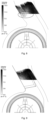
Fig. 6 illustrates an air flow distribution view of an air duct part of a volute in the art known to inventors; -
Fig. 7 illustrates an air flow distribution view of an air duct part according to the embodiment of the volute shown inFig. 1 ; -
Fig. 8 illustrates a cross-sectional view of air flow velocity distribution of the air duct part of the volute in the prior art; and -
Fig. 9 illustrates a cross-sectional view of air flow velocity distribution of the air duct part according to the embodiment of the volute shown inFig. 1 . - The above accompanying drawings have the following reference numerals:
- 1. volute main body; 2. fan blade assembly; 3. fan blade mounting part; 4. air duct part; 5. first air duct molded line; 6. second air duct molded line; 7. volute tongue;
- 8. convex hull; 81. upper surface; 82. first side surface; 83. second side surface; 84. third side surface; 85. fourth side surface.
- It should be noted that in the case of no conflict, embodiments in the present invention and features in the embodiments are combined with each other. The present invention will be described in detail below with reference to the accompanying drawings in conjunction with the embodiments.
- As shown in
Fig. 1 to Fig. 5 , the present invention provides a volute, including: a volute main body 1, wherein the volute main body 1 includes a fan blade mounting part 3 used for mounting a fan blade assembly 2 and two air duct parts 4 disposed on two sides of the fan blade mounting part 3 at an interval along a first direction and in communication with the fan blade mounting part 3, and the fan blade mounting part 3 is used for mounting the fan blade assembly 2; a first air duct molded line 5 and a second air duct molded line 6 are respectively formed between two opposite sides, disposed at an interval along a second direction, of each air duct part 4 and the fan blade mounting part 3, a joint between a side, close to the first air duct molded line 5, of each of the two air duct parts 4 and the fan blade mounting part 3 is disposed in a streamline mode, and a volute tongue 7 is disposed at the joint between a side, close to the second air duct molded line 6, of each of the two air duct parts 4 and the fan blade mounting part 3; and convex hulls 8 protruding towards a direction away from a corresponding air duct part 4 are disposed on two opposite sides, disposed at an interval along a rotating axis of the fan blade assembly 2, of at least one air duct part 4; wherein the first direction and the second direction are perpendicular to each other and are both perpendicular to the rotating axis of the fan blade assembly 2. - In this way, by disposing the first air duct molded
line 5, the second air duct moldedline 6 and theconvex hulls 8 for the volute of the present invention, the air volume of a double-suction single-centrifugal fan is increased, the phenomenon of uneven air flow velocity distribution in an air duct is improved, the aerodynamic noise of the double-suction centrifugal fan is reduced, and the working performance of the centrifugal fan is increased. Moreover, the flow direction of the outlet air flow is adjusted, the phenomenon of air flow return can be effectively suppressed in different air sensing modes, vortices in the air duct are effectively reduced, the air flow loss is reduced, the noise problems such as outlet air duct surge and discontinuous air flow are improved, the comfort experience of users is increased, and the problems of relatively low fan efficiency of a single-centrifugal double-suction fan and discontinuous aerodynamic noise at a volute outlet in the prior art are solved. - As shown in
Fig. 3 andFig. 4 , the convex hull 8 includes: an upper surface 81, the upper surface 81 and the air duct part 4 being disposed at an interval; a first side surface 82 and a second side surface 83, the first side surface 82 and the second side surface 83 being respectively located on two opposite sides, disposed at an interval along an extension direction of the air duct part 4, of the upper surface 81, the first side surface 82 being located on a side, away from the fan blade mounting part 3, of the upper surface 81, and the second side surface 83 being located on a side, close to the fan blade mounting part 3, of the upper surface 81; and a third side surface 84 and a fourth side surface 85, the third side surface 84 and the fourth side surface 85 being respectively located on two opposite sides, disposed at an interval along a direction perpendicular to the extension direction of the air duct part 4, of the upper surface 81, the third side surface 84 being located on a side, close to the first air duct molded line 5, of the upper surface 81, and the fourth side surface 85 being located on a side, close to the second air duct molded line 6, of the upper surface 81, wherein the upper surface 81 is connected with an outer surface of the air duct part 4 through the first side surface 82, the second side surface 83, the third side surface 84 and the fourth side surface 85. - In the first and second embodiments of the present invention, an inner wall surface of the side, close to the
volute tongue 7, of theconvex hull 8 is connected with an inner wall surface of the side, close to thevolute tongue 7, of the volutemain body 1, so as to guide the flow direction of the air flow to reduce the mutual impact of the air flow, thereby reducing vortices in an air cavity and reducing the surge noise. - In the first embodiment of the present invention, a calculation formula of the first air duct molded
line 5 is: y = A 2 + (A 1 - A 2)/(1+ exp((x - x 0)/p)), wherein A 1 = -4.87548±1.01258 A 2 =138.4272±1.22718, x 0 =196.19628±1.3696, and p = 55.53854±1.52501; x represents a size of the first air duct moldedline 5 in the second direction by taking an intersection point between a straight line parallel to the second direction and passing through the rotating axis of thefan blade assembly 2 and a side, close to the first air duct moldedline 5, of the volutemain body 1 as a starting point; and y represents a size of the first air duct moldedline 5 in the first direction by taking the rotating axis of thefan blade assembly 2 as a starting point. - In the first embodiment of the present invention, the calculation formula of the second air duct molded
line 6 is: l = (0.3 ~ 0.6)L arcsin θ, wherein L represents a total length of an air duct, wherein 300 mm≤L≤400 mm; θ represents an included angle between the extension direction of the second air duct moldedline 6 and the second direction, wherein 55°≤θ≤65°; and I represents a length of the second air duct moldedline 6. - In the first embodiment of the present invention, a minimum distance between the
convex hull 8 and thevolute tongue 7 is c, wherein 0≤c≤5 mm; a width of theconvex hull 8 in a extension direction of theair duct part 4 is a, wherein 65 mm≤a≤75 mm; a length of theconvex hull 8 in a direction perpendicular to the extension direction of theair duct part 4 is b, wherein 65 mm≤b≤75 mm; and a height of theconvex hull 8 in a direction parallel to the rotating axis of thefan blade assembly 2 is h, wherein 8 mm≤h≤12 mm. - In the first embodiment of the present invention, an included angle between the
upper surface 81 and thefirst side surface 82 is β, wherein 15°≤β≤25°; an included angle between theupper surface 81 and thesecond side surface 83 is α, wherein 30°≤α≤40°; and an included angle between theupper surface 81 and thefourth side surface 85 is γ, wherein 40°≤γ≤50°. - In this way, the performance of a bidirectional centrifugal fan can be effectively increased, the production cost can be reduced, and the effects of adjusting the flow direction of the air flow in the outlet air duct and increasing the air volume of the fan can be achieved in different air sensing modes. In a case of slightly worse experience that an air deflector is rear-mounted, the phenomenon of air flow return can also be effectively suppressed, vortices in the air duct are reduced, the flow field of the air flow in the air duct of the fan is improved, the aerodynamic noise of the fan is reduced, the overall sound quality of the fan is better, and the comfort experience of users is increased.
- In the second embodiment of the present invention, an inner wall surface of the side, close to the
volute tongue 7, of theconvex hull 8 is connected with an inner wall surface of a side, close to thevolute tongue 7, of the volutemain body 1, and an inner wall surface of the side, away from thevolute tongue 7, of theconvex hull 8 is connected to an inner wall surface of the side, away from thevolute tongue 7, of the volutemain body 1, so as to adjust the flow direction of the air flow to reduce the mutual impact of the air flow and reduce vortices in an air cavity, thereby reducing the surge noise. - In the second embodiment of the present invention, the calculation formula of the second air duct molded
line 6 is: L = (1.8 ~ 2.5)l sin θ, wherein L represents a total length of the air duct, wherein 300 mm≤L≤400 mm; θ represents an included angle between the extension direction of the second air duct moldedline 6 and the second direction, wherein 55°≤θ≤65°; and I represents a length of the second air duct moldedline 6. - In the second embodiment of the present invention, a minimum distance between the
convex hull 8 and thevolute tongue 7 is c, wherein 0≤c≤5 mm; a width of theconvex hull 8 in a extension direction of theair duct part 4 is a, wherein 65 mm≤a≤75 mm; a length of theconvex hull 8 in a direction perpendicular to the extension direction of theair duct part 4 is b, wherein 85 mm≤b≤95 mm; and a height of theconvex hull 8 in a direction parallel to the rotating axis of thefan blade assembly 2 is h, wherein 8 mm≤h≤12 mm. - In the third embodiment of the present invention, a gap is respectively reserved between two inner wall surfaces, close to the first air duct molded
line 5 and the second air duct moldedline 6 respectively, of theconvex hull 8 and an inner wall surface of the volutemain body 1, so as to adjust the flow direction of the air flow to reduce the mutual impact of the air flow and reduce vortices in an air cavity, thereby reducing the surge noise. - In the third embodiment of the present invention, a calculation formula of the second air duct molded
line 6 is: L = (1.8 ~ 2.5)l sin θ, wherein L represents a total length of the air duct, wherein 300 mm≤L≤400 mm; θ represents an included angle between an extension direction of the second air duct moldedline 6 and the second direction, wherein 55°≤θ≤65°; and I represents a length of the second air duct moldedline 6. - In the third embodiment of the present invention, a minimum distance between the
convex hull 8 and thevolute tongue 7 is c, wherein 0≤c≤5 mm; a width of theconvex hull 8 in a extension direction of theair duct part 4 is a, wherein 65 mm≤a≤75 mm; a length of theconvex hull 8 in a direction perpendicular to the extension direction of theair duct part 4 is b, wherein 50 mm≤b≤60 mm; and a height of theconvex hull 8 in a direction parallel to the rotating axis of thefan blade assembly 2 is h, wherein 8 mm≤h≤12 mm. - As shown in
Fig. 5 , the present invention provides a fan, including the above volute and thefan blade assembly 2 disposed in the volute. - Specifically, an air deflector is also disposed in the fan. By controlling the rotation angle of the air deflector, the air deflector can be tilted forward to send the air flow upward, or the air deflector can be tilted backward to compress the air flow, thereby achieving various air sensing experiences.
- The present invention further provides an air conditioner, including the above fan.
- According to the air flow distribution view of an air duct part of a volute in the prior art as shown in
Fig. 6 , vortices exist in the air duct part and the flow field distribution is uneven, which can easily cause aerodynamic noise, thereby affecting the performance and overall sound quality of the fan. It can be seen from the air flow distribution view of an air duct part of a volute of the present invention as shown inFig. 7 that the volute of the present invention greatly improves the above problems. - According to the cross-sectional view of air flow velocity distribution of the air duct part of the volute in the prior art as shown in
Fig. 8 , the air flow in the air duct can return, resulting in return loss, so that on the one hand, the air volume is reduced, and the work efficiency of the volute is reduced; and on the other hand, larger aerodynamic noise is generated by air flow return. It can be seen from the cross-sectional view of air flow velocity distribution of the air duct part of the volute of the present invention as shown inFig. 9 that the volute of the present invention greatly improves the above problems. - From the above description, it can be seen that the above embodiments of the present invention achieve the following technical effects:
The volute of the present invention includes: a volute main body 1, wherein the volute main body 1 includes a fan blade mounting part 3 used for mounting a fan blade assembly 2 and two air duct parts 4 disposed on two sides of the fan blade mounting part 3 at an interval along a first direction and in communication with the fan blade mounting part 3, and the fan blade mounting part 3 is used for mounting the fan blade assembly 2; a first air duct molded line 5 and a second air duct molded line 6 are respectively formed between two opposite sides, disposed at an interval along a second direction, of each air duct part 4 and the fan blade mounting part 3, the joint between the side, close to the first air duct molded line 5, of each air duct part 4 and the fan blade mounting part 3 is disposed in a streamline mode, and a volute tongue 7 is disposed at the joint between the side, close to the second air duct molded line 6, of each air duct part 4 and the fan blade mounting part 3; convex hulls 8 protruding towards a direction away from the corresponding air duct part 4 are disposed on two opposite sides, disposed at an interval along a rotating axis of the fan blade assembly 2, of at least one air duct part 4; and the first direction and the second direction are perpendicular to each other and are both perpendicular to the rotating axis of the fan blade assembly 2. In this way, by disposing the first air duct moldedline 5, the second air duct moldedline 6 and theconvex hulls 8 for the volute of the present invention, the air volume of a double-suction single-centrifugal fan is increased, the phenomenon of uneven air flow velocity distribution in an air duct is improved, the aerodynamic noise of the double-suction centrifugal fan is reduced, and the working performance of the centrifugal fan is increased. Moreover, the flow direction of the outlet air flow is adjusted, the phenomenon of air flow return can be effectively suppressed in different air sensing modes, vortices in the air duct are effectively reduced, the air flow loss is reduced, the noise problems such as outlet air duct surge and discontinuous air flow are improved, the comfort experience of users is increased, and the problems of relatively low fan efficiency of a single-centrifugal double-suction fan and discontinuous aerodynamic noise at a volute outlet in the prior art are solved. - It should be noted that the terms used here are only used for describing specific implementations, but are not intended to limit exemplary implementations according to the present invention. As used here, unless explicitly stated in the context, the singular form is also intended to include the plural form. In addition, it should also be understood that when the terms "include" and/or "include" are used in the specification, they indicate the presence of features, steps, operations, devices, assemblies, and/or combinations thereof.
- Unless otherwise specified, the relative disposition, numerical expressions and values of the components and steps described in these embodiments do not limit the scope of the present invention. Furthermore, it should be understood that for ease of description, the sizes of various parts shown in the accompanying drawings are not drawn according to the actual proportional relationship. For technologies, methods and devices known to ordinary technical personnel in related fields, detailed discussions can not be conducted. However, in appropriate situations, the technologies, methods and devices should be considered as part of the authorized specification. In all the examples shown and discussed here, any specific value should be interpreted as illustrative only and not as a limitation. Therefore, other examples of exemplary embodiments can have different values. It should be noted that similar numerals and letters denote similar items in the following accompanying drawings, therefore, once an item is defined in one accompanying drawing, it does not need to be further discussed in subsequent accompanying drawings.
- In the description of the present invention, it should be understood that the orientation or position relationships indicated by orientation words such as "front, back, up, down, left, and right", "horizontal, vertical, perpendicular, and horizontal", and "top and bottom" are usually based on the orientation or position relationships shown in the accompanying drawings, and are only for the convenience of describing the present invention and simplifying the description. Unless otherwise stated, these orientation words do not indicate or imply that the apparatus or component referred to must have a specific orientation or be constructed and operated in a specific orientation, and therefore cannot be understood as limiting the scope of protection of the present invention. The orientation words "inside and outside" refer to the inside and outside of the contour relative to each component.
- For ease of description, spatial relative terms such as "above", "over", "on an upper surface of" and "on the top of" can be used here to describe the spatial position relationship between a device or feature and other devices or features as shown in the accompanying drawings. It should be understood that the spatial relative terms are intended to include different orientations in use or operation other than the orientations of the devices described in the accompanying drawings. For example, if the devices in the accompanying drawings are inverted, the devices described as "over other devices or structures" or "above other devices or structures" will be then positioned as "under other devices or structures" or "below other devices or structures". Therefore, the exemplary term "over" can include two orientations: "over" and "under". The device can also be positioned in other different manners (rotated 90 degrees or in other orientations), and the spatial relative description used here is explained accordingly.
- In addition, it should be noted that using words such as "first" and "second" to define parts is only intended to facilitate the differentiation of corresponding parts. Unless otherwise stated, the above words have no special meanings and therefore cannot be understood as limiting the scope of protection of the present invention.
- The above descriptions are merely preferred embodiments of the present invention, but are not intended to limit the present invention. For those skilled in the art, the present invention can have various modifications and variations. Any modifications, equivalent replacements, improvements, and the like made within the spirit and principle of the present invention shall be included within the scope of protection of the present invention.
Claims (17)
- A volute, comprising:a volute main body (1), wherein the volute main body (1) comprises a fan blade mounting part (3) used for mounting a fan blade assembly (2) and two air duct parts (4) disposed on two sides of the fan blade mounting part (3) at an interval along a first direction and in communication with the fan blade mounting part (3), and the fan blade mounting part (3) is used for mounting the fan blade assembly (2);a first air duct molded line (5) and a second air duct molded line (6) are respectively formed between two opposite sides, disposed at an interval along a second direction, of each air duct part (4) and the fan blade mounting part (3), a joint between a side, close to the first air duct molded line (5), of each of the two air duct parts (4) and the fan blade mounting part (3) is disposed in a streamline mode, and a volute tongue (7) is disposed at a joint between a side, close to the second air duct molded line (6), of each of the two air duct parts (4) and the fan blade mounting part (3); andconvex hulls (8) protruding towards a direction away from a corresponding air duct part (4) are disposed on two opposite sides, disposed at an interval along a rotating axis of the fan blade assembly (2), of at least one air duct part (4);wherein the first direction and the second direction are perpendicular to each other and are both perpendicular to the rotating axis of the fan blade assembly (2).
- The volute according to claim 1, wherein the convex hull (8) comprises:an upper surface (81), the upper surface (81) and the air duct part (4) being disposed at an interval;a first side surface (82) and a second side surface (83), the first side surface (82) and the second side surface (83) being respectively located on two opposite sides, disposed at an interval along an extension direction of the air duct part (4), of the upper surface (81), the first side surface (82) being located on a side, away from the fan blade mounting part (3), of the upper surface (81), and the second side surface (83) being located on a side, close to the fan blade mounting part (3), of the upper surface (81); anda third side surface (84) and a fourth side surface (85), the third side surface (84) and the fourth side surface (85) being respectively located on two opposite sides, disposed at an interval along a direction perpendicular to the extension direction of the air duct part (4), of the upper surface (81), the third side surface (84) being located on a side, close to the first air duct molded line (5), of the upper surface (81), and the fourth side surface (85) being located on a side, close to the second air duct molded line (6), of the upper surface (81),wherein the upper surface (81) is connected with an outer surface of the air duct part (4) through the first side surface (82), the second side surface (83), the third side surface (84) and the fourth side surface (85).
- The volute according to claim 2, wherein an inner wall surface of the side, close to the volute tongue (7), of the convex hull (8) is connected with an inner wall surface of the side, close to the volute tongue (7), of the volute main body (1).
- The volute according to claim 3, wherein a calculation formula of the first air duct molded line (5) is:
 whereinA 1 = -4.87548±1.01258A 2 = 138.4272±1.22718x 0 = 196.19628±1.3696, andp = 55.53854 ± 1.52501;x represents a size of the first air duct molded line (5) in the second direction by taking an intersection point between a straight line parallel to the second direction and passing through the rotating axis of the fan blade assembly (2) and a side, close to the first air duct molded line (5), of the volute main body (1) as a starting point; andy represents a size of the first air duct molded line (5) in the first direction by taking the rotating axis of the fan blade assembly (2) as a starting point.
 - The volute according to claim 4, wherein the calculation formula of the second air duct molded line (6) is:
l = (0.3 ~ 0.6)L arcsin θ, wherein L represents a total length of an air duct, wherein 300 mm≤L≤400 mm; θ represents an included angle between the extension direction of the second air duct molded line (6) and the second direction, wherein 55°≤θ≤65°; and I represents a length of the second air duct molded line (6). - The volute according to claim 4, whereina minimum distance between the convex hull (8) and the volute tongue (7) is c, wherein 0≤c≤5 mm;a width of the convex hull (8) in an extension direction of the air duct part (4) is a, wherein 65 mm≤a≤75 mm;a length of the convex hull (8) in a direction perpendicular to the extension direction of the air duct part (4) is b, wherein 65 mm≤b≤75 mm; anda height of the convex hull (8) in a direction parallel to the rotating axis of the fan blade assembly (2) is h, wherein 8 mm≤h≤12 mm.
- The volute according to claim 5, whereina minimum distance between the convex hull (8) and the volute tongue (7) is c, wherein 0≤c≤5 mm;a width of the convex hull (8) in an extension direction of the air duct part (4) is a, wherein 65 mm≤a≤75 mm;a length of the convex hull (8) in a direction perpendicular to the extension direction of the air duct part (4) is b, wherein 65 mm≤b≤75 mm; anda height of the convex hull (8) in a direction parallel to the rotating axis of the fan blade assembly (2) is h, wherein 8 mm≤h≤12 mm.
- The volute according to claim 6, whereinan included angle between the upper surface (81) and the first side surface (82) is β, wherein 15°≤β≤25°;an included angle between the upper surface (81) and the second side surface (83) is α, wherein 30°≤α≤40°; andan included angle between the upper surface (81) and the fourth side surface (85) is γ, wherein 40°≤γ≤50°.
- The volute according to claim 7, whereinan included angle between the upper surface (81) and the first side surface (82) is β, wherein 15°≤β≤25°;an included angle between the upper surface (81) and the second side surface (83) is α, wherein 30°≤α≤40°; andan included angle between the upper surface (81) and the fourth side surface (85) is γ, wherein 40°≤γ≤50°.
- The volute according to claim 3, wherein an inner wall surface of the side, away from the volute tongue (7), of the convex hull (8) is connected with an inner wall surface of a side, away from the volute tongue (7), of the volute main body (1).
- The volute according to claim 10, wherein the calculation formula of the second air duct molded line (6) is:
 whereinL represents a total length of the air duct, wherein 300 mm≤L≤400 mm;θ represents an included angle between the extension direction of the second air duct molded line (6) and the second direction, wherein 55°≤θ≤65°; andI represents a length of the second air duct molded line (6).
 - The volute according to claim 11, whereina minimum distance between the convex hull (8) and the volute tongue (7) is c, wherein 0≤c≤5 mm;a width of the convex hull (8) in an extension direction of the air duct part (4) is a, wherein 65 mm≤a≤75 mm;a length of the convex hull (8) in a direction perpendicular to the extension direction of the air duct part (4) is b, wherein 85 mm≤b≤95 mm; anda height of the convex hull (8) in a direction parallel to the rotating axis of the fan blade assembly (2) is h, wherein 8 mm≤h≤12 mm.
- The volute according to claim 2, wherein a gap is respectively reserved between two inner wall surfaces, close to the first air duct molded line (5) and the second air duct molded line (6) respectively, of the convex hull (8) and an inner wall surface of the volute main body (1).
- The volute according to claim 13, wherein a calculation formula of the second air duct molded line (6) is:
 whereinL represents a total length of the air duct, wherein 300 mm≤L≤400 mm;θ represents an included angle between an extension direction of the second air duct molded line (6) and the second direction, wherein 55°≤θ≤65°; andI represents a length of the second air duct molded line (6).
 - The volute according to claim 14, whereina minimum distance between the convex hull (8) and the volute tongue (7) is c, wherein 0≤c≤5 mm;a width of the convex hull (8) in an extension direction of the air duct part (4) is a, wherein 65 mm≤a≤75 mm;a length of the convex hull (8) in a direction perpendicular to the extension direction of the air duct part (4) is b, wherein 50 mm≤b≤60 mm; anda height of the convex hull (8) in a direction parallel to the rotating axis of the fan blade assembly (2) is h, wherein 8 mm≤h≤12 mm.
- A fan, comprising the volute according to any one of claims 1 to 15 and the fan blade assembly (2) disposed in the volute.
- An air conditioner, comprising the fan according to claim 16.
Applications Claiming Priority (2)
| Application Number | Priority Date | Filing Date | Title |
|---|---|---|---|
| CN202310615109.5A CN116517883B (en) | 2023-05-26 | 2023-05-26 | Casings, fans and air conditioners |
| PCT/CN2023/141281 WO2024244430A1 (en) | 2023-05-26 | 2023-12-22 | Volute, fan and air conditioner |
Publications (2)
| Publication Number | Publication Date |
|---|---|
| EP4530477A1 true EP4530477A1 (en) | 2025-04-02 |
| EP4530477A4 EP4530477A4 (en) | 2025-12-31 |
Family
ID=87394207
Family Applications (1)
| Application Number | Title | Priority Date | Filing Date |
|---|---|---|---|
| EP23939398.6A Pending EP4530477A4 (en) | 2023-05-26 | 2023-12-22 | SPIRAL HOUSING, BLOWER AND AIR CONDITIONER |
Country Status (3)
| Country | Link |
|---|---|
| EP (1) | EP4530477A4 (en) |
| CN (1) | CN116517883B (en) |
| WO (1) | WO2024244430A1 (en) |
Families Citing this family (3)
| Publication number | Priority date | Publication date | Assignee | Title |
|---|---|---|---|---|
| CN114562807A (en) * | 2022-03-28 | 2022-05-31 | 珠海格力电器股份有限公司 | Air duct assembly and air conditioner indoor unit with same |
| CN116517883B (en) * | 2023-05-26 | 2025-11-21 | 珠海格力电器股份有限公司 | Casings, fans and air conditioners |
| CN116951722B (en) * | 2023-08-07 | 2025-10-24 | 珠海格力电器股份有限公司 | Air duct structure and air conditioner |
Family Cites Families (16)
| Publication number | Priority date | Publication date | Assignee | Title |
|---|---|---|---|---|
| JP3764442B2 (en) * | 2002-09-05 | 2006-04-05 | 三菱電機株式会社 | Stabilizers for air conditioners, cross-flow fans and cross-flow fans |
| JP4631941B2 (en) * | 2008-07-18 | 2011-02-16 | 株式会社デンソー | Centrifugal blower |
| CN108612674A (en) * | 2018-03-22 | 2018-10-02 | 海信科龙电器股份有限公司 | Centrifugal fan and air conditioner |
| CN110439860B (en) * | 2018-05-04 | 2025-04-15 | 宁波方太厨具有限公司 | A volute structure of a centrifugal fan |
| CN210440279U (en) * | 2019-09-02 | 2020-05-01 | 珠海格力电器股份有限公司 | Volute, centrifugal fan and air conditioner |
| CN110566510B (en) * | 2019-09-02 | 2024-12-27 | 珠海格力电器股份有限公司 | Volute, centrifugal fan and air conditioner |
| CN110864009B (en) * | 2019-12-04 | 2025-10-28 | 珠海格力电器股份有限公司 | Volute structure and fan having the same |
| CN111997935B (en) * | 2020-08-27 | 2022-06-07 | 华电章丘发电有限公司 | A noise reduction volute tongue structure and centrifugal fan |
| CN214577815U (en) * | 2021-01-25 | 2021-11-02 | 青岛海尔智能技术研发有限公司 | a centrifugal fan |
| CN113090587B (en) * | 2021-05-18 | 2022-07-22 | 江西斯米克陶瓷有限公司 | Conveying device for ceramic tile process spray tower |
| CN216714810U (en) * | 2021-06-22 | 2022-06-10 | 珠海格力电器股份有限公司 | Volute and warmer |
| CN114962294B (en) * | 2021-07-19 | 2025-08-08 | 青岛经济技术开发区海尔热水器有限公司 | Noise-reducing centrifugal fan and gas water heater |
| CN216044629U (en) * | 2021-11-01 | 2022-03-15 | 北京小米移动软件有限公司 | Centrifugal ducts, air handling units and air conditioners |
| CN218846415U (en) * | 2022-12-21 | 2023-04-11 | 珠海格力电器股份有限公司 | Flow guide structure and air conditioner with same |
| CN218915142U (en) * | 2022-12-21 | 2023-04-25 | 珠海格力电器股份有限公司 | Air conditioner |
| CN116517883B (en) * | 2023-05-26 | 2025-11-21 | 珠海格力电器股份有限公司 | Casings, fans and air conditioners |
-
2023
- 2023-05-26 CN CN202310615109.5A patent/CN116517883B/en active Active
- 2023-12-22 EP EP23939398.6A patent/EP4530477A4/en active Pending
- 2023-12-22 WO PCT/CN2023/141281 patent/WO2024244430A1/en active Pending
Also Published As
| Publication number | Publication date |
|---|---|
| WO2024244430A1 (en) | 2024-12-05 |
| CN116517883A (en) | 2023-08-01 |
| CN116517883B (en) | 2025-11-21 |
| EP4530477A4 (en) | 2025-12-31 |
Similar Documents
| Publication | Publication Date | Title |
|---|---|---|
| EP4530477A1 (en) | Volute, fan and air conditioner | |
| EP3739218A1 (en) | Axial fan blade, axial fan blade assembly, and axial fan duct assembly | |
| CN106593952A (en) | Axial flow fan blade and fan and air conditioner outdoor unit with same | |
| WO2020134066A1 (en) | Shaping method for fan assembly | |
| EP4368901A1 (en) | Fan assembly and air conditioner | |
| CN117366016A (en) | Super-transonic compressor blade grid with alternately inclined grooves on suction surface | |
| JP4663259B2 (en) | Blower and vacuum cleaner | |
| US11988400B2 (en) | Air-outlet duct structure, air-outlet panel and patio type air conditioner indoor unit | |
| CN109282466B (en) | Air duct assembly and air conditioner | |
| US11536290B2 (en) | Fan coil unit and air conditioning system | |
| CN212250585U (en) | Head assembly, air duct system, fan | |
| CN113757171B (en) | Blade assembly, axial flow fan and design method of small blade tip wing | |
| CN116951722B (en) | Air duct structure and air conditioner | |
| WO2025045090A1 (en) | Fan assembly, air conditioner and air conditioning system | |
| CN110701108A (en) | A kind of air cavity assembly and fan | |
| WO2021208497A1 (en) | Head assembly, air duct system, and fan | |
| CN116044514B (en) | Turbos and turbochargers | |
| CN114876831B (en) | Volute structure and range hood | |
| CN113217458B (en) | Impeller, fan system applying impeller and range hood | |
| CN215637547U (en) | Air conditioner indoor unit and air conditioner | |
| CN117543873A (en) | Fan housing of motor and motor | |
| CN214065047U (en) | Deflectors and hoods | |
| CN109000350B (en) | Air duct assembly and air conditioner | |
| EP4549744A1 (en) | Blowing structure and bladeless fan including said blowing structure | |
| CN108844209B (en) | Air duct assembly and air conditioner |
Legal Events
| Date | Code | Title | Description |
|---|---|---|---|
| STAA | Information on the status of an ep patent application or granted ep patent |
Free format text: STATUS: THE INTERNATIONAL PUBLICATION HAS BEEN MADE |
|
| PUAI | Public reference made under article 153(3) epc to a published international application that has entered the european phase |
Free format text: ORIGINAL CODE: 0009012 |
|
| STAA | Information on the status of an ep patent application or granted ep patent |
Free format text: STATUS: REQUEST FOR EXAMINATION WAS MADE |
|
| 17P | Request for examination filed |
Effective date: 20241223 |
|
| AK | Designated contracting states |
Kind code of ref document: A1 Designated state(s): AL AT BE BG CH CY CZ DE DK EE ES FI FR GB GR HR HU IE IS IT LI LT LU LV MC ME MK MT NL NO PL PT RO RS SE SI SK SM TR |
|
| A4 | Supplementary search report drawn up and despatched |
Effective date: 20251203 |
|
| RIC1 | Information provided on ipc code assigned before grant |
Ipc: F04D 29/42 20060101AFI20251127BHEP Ipc: F04D 29/44 20060101ALI20251127BHEP Ipc: F04D 29/66 20060101ALI20251127BHEP Ipc: F24F 1/0022 20190101ALI20251127BHEP |