EP4530441A2 - Thread guard - Google Patents
Thread guard Download PDFInfo
- Publication number
- EP4530441A2 EP4530441A2 EP24202697.9A EP24202697A EP4530441A2 EP 4530441 A2 EP4530441 A2 EP 4530441A2 EP 24202697 A EP24202697 A EP 24202697A EP 4530441 A2 EP4530441 A2 EP 4530441A2
- Authority
- EP
- European Patent Office
- Prior art keywords
- bolt
- guard
- opening
- recited
- connection interface
- Prior art date
- Legal status (The legal status is an assumption and is not a legal conclusion. Google has not performed a legal analysis and makes no representation as to the accuracy of the status listed.)
- Pending
Links
Images


Classifications
-
- F—MECHANICAL ENGINEERING; LIGHTING; HEATING; WEAPONS; BLASTING
- F01—MACHINES OR ENGINES IN GENERAL; ENGINE PLANTS IN GENERAL; STEAM ENGINES
- F01D—NON-POSITIVE DISPLACEMENT MACHINES OR ENGINES, e.g. STEAM TURBINES
- F01D25/00—Component parts, details, or accessories, not provided for in, or of interest apart from, other groups
- F01D25/24—Casings; Casing parts, e.g. diaphragms, casing fastenings
- F01D25/243—Flange connections; Bolting arrangements
-
- F—MECHANICAL ENGINEERING; LIGHTING; HEATING; WEAPONS; BLASTING
- F01—MACHINES OR ENGINES IN GENERAL; ENGINE PLANTS IN GENERAL; STEAM ENGINES
- F01D—NON-POSITIVE DISPLACEMENT MACHINES OR ENGINES, e.g. STEAM TURBINES
- F01D25/00—Component parts, details, or accessories, not provided for in, or of interest apart from, other groups
- F01D25/24—Casings; Casing parts, e.g. diaphragms, casing fastenings
- F01D25/26—Double casings; Measures against temperature strain in casings
- F01D25/265—Vertically split casings; Clamping arrangements therefor
-
- F—MECHANICAL ENGINEERING; LIGHTING; HEATING; WEAPONS; BLASTING
- F16—ENGINEERING ELEMENTS AND UNITS; GENERAL MEASURES FOR PRODUCING AND MAINTAINING EFFECTIVE FUNCTIONING OF MACHINES OR INSTALLATIONS; THERMAL INSULATION IN GENERAL
- F16B—DEVICES FOR FASTENING OR SECURING CONSTRUCTIONAL ELEMENTS OR MACHINE PARTS TOGETHER, e.g. NAILS, BOLTS, CIRCLIPS, CLAMPS, CLIPS OR WEDGES; JOINTS OR JOINTING
- F16B37/00—Nuts or like thread-engaging members
- F16B37/12—Nuts or like thread-engaging members with thread-engaging surfaces formed by inserted coil-springs, discs, or the like; Independent pieces of wound wire used as nuts; Threaded inserts for holes
- F16B37/122—Threaded inserts, e.g. "rampa bolts"
-
- F—MECHANICAL ENGINEERING; LIGHTING; HEATING; WEAPONS; BLASTING
- F05—INDEXING SCHEMES RELATING TO ENGINES OR PUMPS IN VARIOUS SUBCLASSES OF CLASSES F01-F04
- F05D—INDEXING SCHEME FOR ASPECTS RELATING TO NON-POSITIVE-DISPLACEMENT MACHINES OR ENGINES, GAS-TURBINES OR JET-PROPULSION PLANTS
- F05D2230/00—Manufacture
- F05D2230/60—Assembly methods
-
- F—MECHANICAL ENGINEERING; LIGHTING; HEATING; WEAPONS; BLASTING
- F05—INDEXING SCHEMES RELATING TO ENGINES OR PUMPS IN VARIOUS SUBCLASSES OF CLASSES F01-F04
- F05D—INDEXING SCHEME FOR ASPECTS RELATING TO NON-POSITIVE-DISPLACEMENT MACHINES OR ENGINES, GAS-TURBINES OR JET-PROPULSION PLANTS
- F05D2260/00—Function
- F05D2260/30—Retaining components in desired mutual position
- F05D2260/31—Retaining bolts or nuts
-
- F—MECHANICAL ENGINEERING; LIGHTING; HEATING; WEAPONS; BLASTING
- F16—ENGINEERING ELEMENTS AND UNITS; GENERAL MEASURES FOR PRODUCING AND MAINTAINING EFFECTIVE FUNCTIONING OF MACHINES OR INSTALLATIONS; THERMAL INSULATION IN GENERAL
- F16B—DEVICES FOR FASTENING OR SECURING CONSTRUCTIONAL ELEMENTS OR MACHINE PARTS TOGETHER, e.g. NAILS, BOLTS, CIRCLIPS, CLAMPS, CLIPS OR WEDGES; JOINTS OR JOINTING
- F16B2200/00—Constructional details of connections not covered for in other groups of this subclass
- F16B2200/50—Flanged connections
- F16B2200/503—Flanged connections the flange being separate from the elements to be connected
-
- F—MECHANICAL ENGINEERING; LIGHTING; HEATING; WEAPONS; BLASTING
- F16—ENGINEERING ELEMENTS AND UNITS; GENERAL MEASURES FOR PRODUCING AND MAINTAINING EFFECTIVE FUNCTIONING OF MACHINES OR INSTALLATIONS; THERMAL INSULATION IN GENERAL
- F16B—DEVICES FOR FASTENING OR SECURING CONSTRUCTIONAL ELEMENTS OR MACHINE PARTS TOGETHER, e.g. NAILS, BOLTS, CIRCLIPS, CLAMPS, CLIPS OR WEDGES; JOINTS OR JOINTING
- F16B2200/00—Constructional details of connections not covered for in other groups of this subclass
- F16B2200/50—Flanged connections
- F16B2200/506—Flanged connections bolted or riveted
Definitions
- the present disclosure relates generally to a bolt assembly for a joint between component structures of an aircraft engine.
- a gas turbine engine typically includes a fan section, a compressor section, a combustor section, and a turbine section.
- Many engine structures are secured by a bolt assembly that extends through a flanged connection.
- the flanged connection includes openings through separate parts through which the bolt assembly extends. Shear forces acting transverse to a length of the bolt assembly may result in contact between exposed bolt threads and an inner surface of the openings. Contact and engagement between the inner surface of the opening and the bolt threads may reduce strength and longevity of the connection.
- a connection interface between components of a turbine engine includes, among other possible things, a first component defining a first flange with a first opening, a second component defining a second flange with a second opening, a bolt including a shaft with external threads extending from a bolt head to a distal end. The shaft extends through both the first opening and the second opening.
- a guard is provided that includes internal threads, a first end, a second end and an outer surface shaped to fit within both of the first opening and the second opening.
- the connection further includes a nut including internal threads secured to the external threads of the bolt.
- a bolt assembly for connecting component sections of an aircraft component includes, among other things, a bolt including a shaft having external threads extending from a bolt head to a distal end and a guard including internal threads mated to the external threads of the bolt.
- the guard further includes a first end, a second end and an outer surface having a uniform diameter between the first end and the second end.
- the bolt assembly further includes a nut including internal threads securable to the external threads of the bolt.
- a method of securing component parts of an aircraft engine includes, among other possible things, aligning a first opening of a first component with a second opening of second component, mating internal threads of a guard to external threads of a bolt, inserting the mated bolt and guard through the first opening and the second opening, mating a nut to external threads of the bolt that extend outside of the first opening and the second opening, and tightening the nut against a surface of one of the first component and the second component to a predetermined torque.
- Figure 1 schematically illustrates an aircraft turbine engine 20.
- the example engine 20 includes a bolt assembly 42 utilized to secure engine structures together at a flanged connection.
- the example bolt assembly 42 includes features for accommodating shear loads on the flanged connection.
- the example turbine engine 20 is a turbofan that generally incorporates a fan section 22, a compressor section 24, a combustor section 26 and a turbine section 28.
- the fan section 22 drives air along a bypass flow path B in a bypass duct defined within a nacelle 30.
- the fan section 22 also drives air along a core flow path C into the compressor section 24 for compression and communication into the combustor section 26.
- the compressed air is mixed with fuel and burnt to generate an exhaust gas flow that expands through the turbine section 28.
- the turbine engine 20 includes case components that circumscribe rotating components described above.
- a first case component 34 is secured to a second case component 38 at a bolted connection interface 32.
- the first case component 34 includes a first flange 36 and the second case component 38 includes a second flange 40.
- the case components 34, 38 are secured to each other by a bolt assembly 42 that extends through each of the first and second flanges 36, 40.
- a bolt assembly may be utilizes for securement of other engine structures and aircraft components.
- a bolt assembly 112 is shown as art of a connection interface 108 between an engine mount 110 and an aircraft structure 114 as is schematically shown.
- the disclosed bolt assemblies 42, 112 may be utilized for any bolted joint utilized as part of an engine and/or aircraft structure.
- a prior art bolt assembly 44 is schematically shown and includes bolt 46 with threads 50 that extend through openings in abutted flanges.
- a nut 48 is assembled to the threads 50 to secure the flanges together.
- the connection shown is an example of a connection that encounters shear loads indicated by arrows 54 in a direction perpendicular to a longitudinal length of the bolt 46. Exposure of the threads 50 to excessive shear forces within the joint can cause harmful interaction with inner surfaces 52 of the openings.
- the threads 50 are formed with peaks that can concentrate shear loads in the bolt 56 that may reduce joint durability and longevity.
- an example bolt assembly 42 includes a bolt 56 with a shaft 60 having external threads 62 that extend from a bolt head 58 to a distal end 98.
- a thread guard 64 is assembled onto the external threads 62 of the bolt 56.
- the thread guard 64 includes internal threads 66 that mate to the external threads 62 of the bolt 56.
- a nut 74 is secured to the bolt 56 and is tightened to a predetermined torque to hold the first flange 36 to the second flange 40.
- the example bolted connection interface 32 is exposed to shear loads schematically indicated by arrows 54 that are perpendicular to a longitudinal length of the bolt shaft 60.
- the first flange 36 includes a first opening 70 and the second flange 40 includes a second opening 72.
- the bolt 56 and thread guard 64 extend through the aligned first opening 70 and the second opening 72.
- the thread guard 64 includes an outer surface 68 with a uniform outer diameter 88 that contacts inner surfaces of the first and second openings 70, 72.
- the shear load 54 is distributed across the outer surface 68 of the guard 64.
- the guard 64 prevents contact between inner surfaces of the first and second openings 70, 72 and the threads 62 of the bolt 56.
- the uniform diameter 88 is not interrupted circumferentially and provides a constant and uniform surface that is not interrupted by torque application surfaces such as are commonly provided for a nut.
- the bolted connection interface 32 is formed by installing the guard 64 onto the bolt 56.
- the internal threads 66 of the guard 64 correspond to the external threads 62 of the bolt 56.
- the guard 64 includes a head portion 76 that abuts the bolt head 58.
- the guard 64 is threaded onto the bolt 56 until the head portion 76 abuts the bolt head 58.
- a length 86 of the guard 64 is shorter than a combined thickness 106 of the first flange 36 and the second flange 40. The shorter length of the guard 64 prevents interference with tightening of the nut 74 to hold the flanges 36, 40 together.
- the nut 74 is threaded onto the exposed portion of the bolt threads 62 and tightened against the flange 40.
- the first and second openings 70 and 72 are sized to accommodate the guard 64 instead of the outer diameter of just the bolt shaft 60.
- the first opening 70 includes a first diameter 102 and the second opening 72 includes a second diameter 104.
- the first and second diameters 102, 104 are the same.
- the first and second openings 70, 72 are round and the outer surface 68 of the guard is also a corresponding round shape.
- the openings through the flanges and the guard may be of other shapes and remain within the contemplation and scope of this disclosure.
- a fit between the outer diameter 88 of the guard 64 and the first and second diameters 102, 104 is dependent on the application.
- the difference between the outer diameter 88 and the first and second diameters 102, 104 may define a loose to tight clearance fit that eases assembly while also minimizing potential relative movement.
- the outer diameter 88 is between about 85% and 95% of at least one of the diameters 102, 104 of each of the first opening 70 and the second opening 72.
- the uniform outer surface 68 of the guard 64 provides a uniform and large contact area with the inner surfaces of the first and second openings 70, 72.
- the large contact surface distributes loads across a large area that increases joint strength and longevity.
- the example nut 74 is hexagon shaped and includes a width 116 that provides for abutment against the outer surface of the flange 40. Moreover, the hexagon shaped of the nut 74 provides surfaces for the application of torque for tightening.
- the nut 74 includes internal threads 75 that engage and mate to the threads 62 of the bolt 56. The nut 74 abuts against one surface of the flange 40 and is tightened to a predetermined torque prescribed for the specific bolted connection interface.
- the nut 74 is disclosed by way of example as having a hexagonal shape, other shapes that provide for the application of torque may also be utilized and are within the contemplation of this disclosure.
- the example thread guard 64 is shown with an example bolt 56 to illustrate relative sizes between features.
- the bolt 56 includes the bolt head 58 with a width 82.
- the bolt head 58 may be a hexagon shaped or have other shapes to provide surfaces that accommodate the application of torque.
- the thread guard 64 includes a length 86 between a first end 63 and a second end 65 that is between 65% and 85% of a length 78 of the shaft 60 between a bottom surface 84 of the bolt head 58 and the distal end 98. In another example embodiment, the length 86 is between 70% and 80% the length 78 of the shaft 60.
- the outer diameter 88 of the guard 64 is between 60% and 85% of a maximum width 82 of the bolt head 58. In another example embodiment, the outer diameter 88 is between 70% and 80% of the maximum width 82 of the bolt head 58.
- the guard 64 includes a thickness 92 between a pitch diameter 90 of the internal threads 66 and the outer surface 68 that is between 10% and 25% of a pitch diameter 80 of the external threads 62 of the bolt 56. In another example embodiment, the thickness 92 is between 15% and 20% of the pitch diameter 80.
- the example guard 64 includes the head portion 76 that abuts the bottom surface 84 of the bolt head 58.
- the head portion 76 prevents further movement of the guard relative to the bolt 56.
- the head portion 76 includes an abutment surface 94 that is configured to abut the bottom surface 84 of the bolt head 58.
- the head portion 76 further includes an inner spacing 96 between a first one 100 of the internal threads 66 and the abutment surface 94. In a disclosed example embodiment, the spacing 96 is equal to or greater than a pitch 118 of the external threads 62 of the bolt 56.
- the head portion 76 provides a relief that enables direct abutment against the bolt head 58 without interference that may be caused at the interface between the bottom surface 84 of the bolt head 58 and the shaft 60.
- the guard 64 and bolt 56 are formed from the same material.
- the material may include steel, aluminum and/or alloys selected based on application specific requirements.
- the diameter and length of the bolt 56 and guard 64 will vary based on the application and securement requirements.
- the example bolt assembly 42 includes the guard 64 that enables the use of a threaded bolt within connections under shear loading to provide increased strength and durability.
- a connection interface 32, 108 between components of a turbine engine 20 includes, among other possible things, a first component 34 defining a first flange 36 with a first opening 70, a second component 38 defining a second flange 40 with a second opening 72, a bolt 56 including a shaft 60 with external threads extending from a bolt head to a distal end, wherein the shaft 60 extends through both the first opening 70 and the second opening 72, a guard 64 including internal threads 66, a first end 63, a second end 65 and an outer surface 68 shaped to fit within both of the first opening 70 and the second opening 72, and a nut 74 including internal threads 75 secured to the external threads of the bolt 56.
- the guard 64 includes a length 86 that is less than a combined thickness 106 of the first flange 36 and the second flange 40.
- the outer surface 68 of the guard 64 is of a uniform diameter 88 along the entire length 86 between the first end 63 and the second end 65.
- the uniform outer diameter 88 of the guard 64 is between about 85% and 95% of a diameter 102, 104 of at least one of the first opening 70 and the second opening 72.
- the uniform outer diameter 88 of the guard 64 is between 60% and 85% of a maximum width 82 of the bolt head 58.
- a thickness 92 of the guard 64 between a pitch diameter 90 of the internal threads 66 and the outer surface 68 is between 10% and 25% of a pitch diameter 80 of the external threads 62 of the bolt 56.
- the guard 64 includes a head portion 76 including an abutment surface 94 configured to abut a bottom surface 84 of the bolt head 58 and an inner surface that defines a spacing 96 between a first one 100 of the internal threads 66 and the abutment surface 94.
- the spacing 96 is equal to or greater than a pitch 118 of the external threads 62 of the bolt 56.
- connection interface 32, 108, the guard 64 and the bolt 56 are formed from a common material.
- a bolt assembly 42, 108 for connecting component sections of an aircraft component includes, among other things, a bolt 56 including a shaft 60 having external threads 62 extending from a bolt head 58 to a distal end 98 and a guard 64 including internal threads 66 mated to the external threads 62 of the bolt 56, a first end 63, a second end 65 and an outer surface 68 having a uniform diameter 88 between the first end 63 and the second end 65.
- the bolt assembly 42 further includes a nut 74 including internal threads 75 securable to the external threads 62 of the bolt 56.
- a length 86 of the guard 64 between the first end 63 and the second end 65 is between 65% and 85% of the length 78 between the bolt head 58 and the distal end 98 of the bolt 56.
- a thickness 92 of the guard 64 between a pitch diameter 90 of the internal threads 66 and the outer surface 68 is between 10% and 25% of a pitch diameter 80 of the external threads 62 of the bolt 56.
- an outer diameter 88 of the guard 64 is between 70% and 85% of a width 82 of the bolt head.
- the spacing 96 is equal to or greater than a pitch 118 of the external threads 62 of the bolt 56.
- the guard and the bolt 56 are formed from a common material.
- a method of securing component parts of an aircraft engine 20 includes, among other possible things, aligning a first opening 70 of a first component 34 with a second opening 72 of second component 38, mating internal threads 66 of a guard 64 to external threads 62 of a bolt 56, inserting the mated bolt 56 and guard 64 through the first opening 70 and the second opening 72, mating a nut 74 to external threads 62 of the bolt 56 that extend outside of the first opening 70 and the second opening 72, and tightening the nut 74 against a surface of one of the first component 34 and the second component 38 to a predetermined torque.
- the guard 64 includes an outer surface 68 corresponding with a shape of an inner surface of each of the first opening 70 and the second opening 72.
- the outer surface 68 of the guard 64 is of a uniform diameter 88 that is between 85% and 95% of a diameter 102, 104 of each of the first opening 70 and the second opening 72.
- the guard 64 includes a head portion 76 with an abutment surface 94 configured to abut a bottom surface 84 of a head 58 of the bolt 56 and an inner surface defining a spacing 96 between a first one 100 of the internal threads 66 and the abutment surface 94 and mating the guard to the bolt 56 includes threading the guard 64 onto the bolt 56 until the abutment surface 94 contacts the bottom surface 84 of the head 58 of the bolt 56.
Landscapes
- Engineering & Computer Science (AREA)
- General Engineering & Computer Science (AREA)
- Mechanical Engineering (AREA)
- Connection Of Plates (AREA)
Abstract
Description
- The present disclosure relates generally to a bolt assembly for a joint between component structures of an aircraft engine.
- A gas turbine engine typically includes a fan section, a compressor section, a combustor section, and a turbine section. Many engine structures are secured by a bolt assembly that extends through a flanged connection. The flanged connection includes openings through separate parts through which the bolt assembly extends. Shear forces acting transverse to a length of the bolt assembly may result in contact between exposed bolt threads and an inner surface of the openings. Contact and engagement between the inner surface of the opening and the bolt threads may reduce strength and longevity of the connection.
- A connection interface between components of a turbine engine according to an example disclosed embodiment includes, among other possible things, a first component defining a first flange with a first opening, a second component defining a second flange with a second opening, a bolt including a shaft with external threads extending from a bolt head to a distal end. The shaft extends through both the first opening and the second opening. A guard is provided that includes internal threads, a first end, a second end and an outer surface shaped to fit within both of the first opening and the second opening. The connection further includes a nut including internal threads secured to the external threads of the bolt.
- A bolt assembly for connecting component sections of an aircraft component according to another disclosed example embodiment includes, among other things, a bolt including a shaft having external threads extending from a bolt head to a distal end and a guard including internal threads mated to the external threads of the bolt. The guard further includes a first end, a second end and an outer surface having a uniform diameter between the first end and the second end. The bolt assembly further includes a nut including internal threads securable to the external threads of the bolt.
- A method of securing component parts of an aircraft engine according to disclosed example embodiment includes, among other possible things, aligning a first opening of a first component with a second opening of second component, mating internal threads of a guard to external threads of a bolt, inserting the mated bolt and guard through the first opening and the second opening, mating a nut to external threads of the bolt that extend outside of the first opening and the second opening, and tightening the nut against a surface of one of the first component and the second component to a predetermined torque.
- Although the different examples have the specific components shown in the illustrations, embodiments of this disclosure are not limited to those particular combinations. It is possible to use some of the components or features from one of the examples in combination with features or components from another one of the examples.
- These and other features disclosed herein can be best understood from the following specification and drawings, the following of which is a brief description.
-
-
Figure 1 is a schematic view of an example gas turbine engine. -
Figure 2 is a schematic view of a prior art bolted j oint. -
Figure 3 is a schematic view of an example bolted connection interface. -
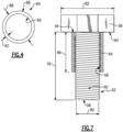
Figure 4 is a top view of an example guard embodiment. -
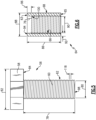
Figure 5 is a schematic view of an example bolt. -
Figure 6 is a cross-sectional view of an example guard embodiment. -
Figure 7 is a cross-sectional view of the example guard assembled to the bolt. -
Figure 1 schematically illustrates anaircraft turbine engine 20. Theexample engine 20 includes abolt assembly 42 utilized to secure engine structures together at a flanged connection. Theexample bolt assembly 42 includes features for accommodating shear loads on the flanged connection. - The
example turbine engine 20 is a turbofan that generally incorporates afan section 22, acompressor section 24, acombustor section 26 and aturbine section 28. Thefan section 22 drives air along a bypass flow path B in a bypass duct defined within anacelle 30. Thefan section 22 also drives air along a core flow path C into thecompressor section 24 for compression and communication into thecombustor section 26. In thecombustor section 26, the compressed air is mixed with fuel and burnt to generate an exhaust gas flow that expands through theturbine section 28. Although depicted as a turbofan turbine engine in the disclosed non-limiting embodiment, it should be understood that the concepts described herein are not limited to use with turbofans as the teachings may be applied to other types of aircraft engines and structures. - The
turbine engine 20 includes case components that circumscribe rotating components described above. In the example schematic illustration, afirst case component 34 is secured to asecond case component 38 at a boltedconnection interface 32. Thefirst case component 34 includes afirst flange 36 and thesecond case component 38 includes asecond flange 40. Thecase components bolt assembly 42 that extends through each of the first andsecond flanges - Additionally, a bolt assembly according to this disclosure may be utilizes for securement of other engine structures and aircraft components. For example, a
bolt assembly 112 is shown as art of aconnection interface 108 between anengine mount 110 and an aircraft structure 114 as is schematically shown. Moreover, the disclosedbolt assemblies - Referring to
Figure 2 , a priorart bolt assembly 44 is schematically shown and includesbolt 46 withthreads 50 that extend through openings in abutted flanges. Anut 48 is assembled to thethreads 50 to secure the flanges together. The connection shown is an example of a connection that encounters shear loads indicated byarrows 54 in a direction perpendicular to a longitudinal length of thebolt 46. Exposure of thethreads 50 to excessive shear forces within the joint can cause harmful interaction withinner surfaces 52 of the openings. Thethreads 50 are formed with peaks that can concentrate shear loads in thebolt 56 that may reduce joint durability and longevity. - Referring to
Figure 3 with continued reference toFigure 1 anexample bolt assembly 42 according to this disclosure includes abolt 56 with ashaft 60 havingexternal threads 62 that extend from abolt head 58 to adistal end 98. Athread guard 64 is assembled onto theexternal threads 62 of thebolt 56. Thethread guard 64 includesinternal threads 66 that mate to theexternal threads 62 of thebolt 56. Anut 74 is secured to thebolt 56 and is tightened to a predetermined torque to hold thefirst flange 36 to thesecond flange 40. - The example bolted
connection interface 32 is exposed to shear loads schematically indicated byarrows 54 that are perpendicular to a longitudinal length of thebolt shaft 60. Thefirst flange 36 includes a first opening 70 and thesecond flange 40 includes a second opening 72. Thebolt 56 andthread guard 64 extend through the alignedfirst opening 70 and the second opening 72. - Referring to
Figure 4 , with continued reference toFigure 3 , thethread guard 64 includes anouter surface 68 with a uniformouter diameter 88 that contacts inner surfaces of the first andsecond openings shear load 54 is distributed across theouter surface 68 of theguard 64. Moreover, theguard 64 prevents contact between inner surfaces of the first andsecond openings threads 62 of thebolt 56. Theuniform diameter 88 is not interrupted circumferentially and provides a constant and uniform surface that is not interrupted by torque application surfaces such as are commonly provided for a nut. - The bolted
connection interface 32 is formed by installing theguard 64 onto thebolt 56. Theinternal threads 66 of theguard 64 correspond to theexternal threads 62 of thebolt 56. Theguard 64 includes ahead portion 76 that abuts thebolt head 58. Theguard 64 is threaded onto thebolt 56 until thehead portion 76 abuts thebolt head 58. Alength 86 of theguard 64 is shorter than a combinedthickness 106 of thefirst flange 36 and thesecond flange 40. The shorter length of theguard 64 prevents interference with tightening of thenut 74 to hold theflanges - The
nut 74 is threaded onto the exposed portion of thebolt threads 62 and tightened against theflange 40. The first andsecond openings guard 64 instead of the outer diameter of just thebolt shaft 60. Thefirst opening 70 includes afirst diameter 102 and thesecond opening 72 includes asecond diameter 104. In one disclosed example, the first andsecond diameters second openings outer surface 68 of the guard is also a corresponding round shape. However, the openings through the flanges and the guard may be of other shapes and remain within the contemplation and scope of this disclosure. - A fit between the
outer diameter 88 of theguard 64 and the first andsecond diameters outer diameter 88 and the first andsecond diameters outer diameter 88 is between about 85% and 95% of at least one of thediameters first opening 70 and thesecond opening 72. - Although an example relative size is disclosed by way of an example fit, other relative sizes between the opening
diameters outer diameter 88 of theguard 64 may be utilized and are within the contemplation and scope of this disclosure. - The uniform
outer surface 68 of theguard 64 provides a uniform and large contact area with the inner surfaces of the first andsecond openings - The
example nut 74 is hexagon shaped and includes awidth 116 that provides for abutment against the outer surface of theflange 40. Moreover, the hexagon shaped of thenut 74 provides surfaces for the application of torque for tightening. Thenut 74 includesinternal threads 75 that engage and mate to thethreads 62 of thebolt 56. Thenut 74 abuts against one surface of theflange 40 and is tightened to a predetermined torque prescribed for the specific bolted connection interface. Although thenut 74 is disclosed by way of example as having a hexagonal shape, other shapes that provide for the application of torque may also be utilized and are within the contemplation of this disclosure. - Referring to
Figures 5, 6 and7 with continued reference toFigures 3 and4 , theexample thread guard 64 is shown with anexample bolt 56 to illustrate relative sizes between features. Thebolt 56 includes thebolt head 58 with awidth 82. Thebolt head 58 may be a hexagon shaped or have other shapes to provide surfaces that accommodate the application of torque. - In one example embodiment, the
thread guard 64 includes alength 86 between afirst end 63 and asecond end 65 that is between 65% and 85% of alength 78 of theshaft 60 between abottom surface 84 of thebolt head 58 and thedistal end 98. In another example embodiment, thelength 86 is between 70% and 80% thelength 78 of theshaft 60. - In one example embodiment, the
outer diameter 88 of theguard 64 is between 60% and 85% of amaximum width 82 of thebolt head 58. In another example embodiment, theouter diameter 88 is between 70% and 80% of themaximum width 82 of thebolt head 58. - In one example embodiment, the
guard 64 includes athickness 92 between apitch diameter 90 of theinternal threads 66 and theouter surface 68 that is between 10% and 25% of apitch diameter 80 of theexternal threads 62 of thebolt 56. In another example embodiment, thethickness 92 is between 15% and 20% of thepitch diameter 80. - The
example guard 64 includes thehead portion 76 that abuts thebottom surface 84 of thebolt head 58. Thehead portion 76 prevents further movement of the guard relative to thebolt 56. Thehead portion 76 includes anabutment surface 94 that is configured to abut thebottom surface 84 of thebolt head 58. Thehead portion 76 further includes aninner spacing 96 between a first one 100 of theinternal threads 66 and theabutment surface 94. In a disclosed example embodiment, the spacing 96 is equal to or greater than apitch 118 of theexternal threads 62 of thebolt 56. - The
head portion 76 provides a relief that enables direct abutment against thebolt head 58 without interference that may be caused at the interface between thebottom surface 84 of thebolt head 58 and theshaft 60. - In one disclosed example, the
guard 64 andbolt 56 are formed from the same material. The material may include steel, aluminum and/or alloys selected based on application specific requirements. Moreover, the diameter and length of thebolt 56 andguard 64 will vary based on the application and securement requirements. - Accordingly, the
example bolt assembly 42 includes theguard 64 that enables the use of a threaded bolt within connections under shear loading to provide increased strength and durability. - A
connection interface turbine engine 20 according to an example disclosed embodiment includes, among other possible things, afirst component 34 defining afirst flange 36 with afirst opening 70, asecond component 38 defining asecond flange 40 with asecond opening 72, abolt 56 including ashaft 60 with external threads extending from a bolt head to a distal end, wherein theshaft 60 extends through both thefirst opening 70 and thesecond opening 72, aguard 64 includinginternal threads 66, afirst end 63, asecond end 65 and anouter surface 68 shaped to fit within both of thefirst opening 70 and thesecond opening 72, and anut 74 includinginternal threads 75 secured to the external threads of thebolt 56. - In a further example embodiment of the foregoing
connection interface guard 64 includes alength 86 that is less than a combinedthickness 106 of thefirst flange 36 and thesecond flange 40. - In a further example embodiment of any of the foregoing connection interfaces 32, 108, the
outer surface 68 of theguard 64 is of auniform diameter 88 along theentire length 86 between thefirst end 63 and thesecond end 65. - In a further example embodiment of any of the foregoing connection interfaces 32, 108, the uniform
outer diameter 88 of theguard 64 is between about 85% and 95% of adiameter first opening 70 and thesecond opening 72. - In a further example embodiment of any of the foregoing
connection interface outer diameter 88 of theguard 64 is between 60% and 85% of amaximum width 82 of thebolt head 58. - In a further example embodiment of any of the foregoing
connection interface thickness 92 of theguard 64 between apitch diameter 90 of theinternal threads 66 and theouter surface 68 is between 10% and 25% of apitch diameter 80 of theexternal threads 62 of thebolt 56. - In a further example embodiment of any of the foregoing
connection interface guard 64 includes ahead portion 76 including anabutment surface 94 configured to abut abottom surface 84 of thebolt head 58 and an inner surface that defines aspacing 96 between a first one 100 of theinternal threads 66 and theabutment surface 94. - In a further example embodiment of any of the foregoing
connection interface pitch 118 of theexternal threads 62 of thebolt 56. - In a further example embodiment of any of the foregoing
connection interface guard 64 and thebolt 56 are formed from a common material. - A
bolt assembly bolt 56 including ashaft 60 havingexternal threads 62 extending from abolt head 58 to adistal end 98 and aguard 64 includinginternal threads 66 mated to theexternal threads 62 of thebolt 56, afirst end 63, asecond end 65 and anouter surface 68 having auniform diameter 88 between thefirst end 63 and thesecond end 65. Thebolt assembly 42 further includes anut 74 includinginternal threads 75 securable to theexternal threads 62 of thebolt 56. - In a further example embodiment of the foregoing
bolt assembly length 86 of theguard 64 between thefirst end 63 and thesecond end 65 is between 65% and 85% of thelength 78 between thebolt head 58 and thedistal end 98 of thebolt 56. - In a further example embodiment of any of the foregoing
bolt assemblies thickness 92 of theguard 64 between apitch diameter 90 of theinternal threads 66 and theouter surface 68 is between 10% and 25% of apitch diameter 80 of theexternal threads 62 of thebolt 56. - In a further example embodiment of any of the foregoing
bolt assembly outer diameter 88 of theguard 64 is between 70% and 85% of awidth 82 of the bolt head. - In a further example embodiment of any of the foregoing
bolt assembly guard 64 includes ahead portion 76 including anabutment surface 94 configured to abut abottom surface 84 of thebolt head 58 and an inner surface defining aspacing 96 between a first one 100 of theinternal threads 66 and theabutment surface 94. - In a further example embodiment of any of the foregoing
bolt assembly pitch 118 of theexternal threads 62 of thebolt 56. - In a further example embodiment of any of the foregoing
bolt assembly bolt 56 are formed from a common material. - A method of securing component parts of an
aircraft engine 20 according to disclosed example embodiment includes, among other possible things, aligning afirst opening 70 of afirst component 34 with asecond opening 72 ofsecond component 38, matinginternal threads 66 of aguard 64 toexternal threads 62 of abolt 56, inserting the matedbolt 56 andguard 64 through thefirst opening 70 and thesecond opening 72, mating anut 74 toexternal threads 62 of thebolt 56 that extend outside of thefirst opening 70 and thesecond opening 72, and tightening thenut 74 against a surface of one of thefirst component 34 and thesecond component 38 to a predetermined torque. - In a further embodiment of the foregoing method, the
guard 64 includes anouter surface 68 corresponding with a shape of an inner surface of each of thefirst opening 70 and thesecond opening 72. - In a further embodiment of any of the foregoing methods, the
outer surface 68 of theguard 64 is of auniform diameter 88 that is between 85% and 95% of adiameter first opening 70 and thesecond opening 72. - In a further embodiment of any of the foregoing methods, the
guard 64 includes ahead portion 76 with anabutment surface 94 configured to abut abottom surface 84 of ahead 58 of thebolt 56 and an inner surface defining aspacing 96 between a first one 100 of theinternal threads 66 and theabutment surface 94 and mating the guard to thebolt 56 includes threading theguard 64 onto thebolt 56 until theabutment surface 94 contacts thebottom surface 84 of thehead 58 of thebolt 56. - Although an example embodiment has been disclosed, a worker of ordinary skill in this art would recognize that certain modifications would come within the scope of this disclosure. For that reason, the following claims should be studied to determine the scope and content of this disclosure.
Claims (15)
- A connection interface (32; 108) between components of a turbine engine (20) comprising:a first component (34) defining a first flange (36) with a first opening (70);a second component (38) defining a second flange (40) with a second opening (72);a bolt (56) including a shaft (60) with external threads (62) extending from a bolt head (58) to a distal end (98), wherein the shaft (60) extends through both the first opening (70) and the second opening (72);a guard (64) including internal threads (66), a first end (63), a second end (65) and an outer surface (68) shaped to fit within both of the first opening (70) and the second opening (72); anda nut (74) including internal threads (75) secured to the external threads (62) of the bolt (56).
- The connection interface (32; 108) as recited in claim 1, wherein the guard (64) includes a length (86) that is less than a combined thickness (106) of the first flange (36) and the second flange (40).
- The connection interface (32; 108) as recited in claim 1 or 2, wherein the outer surface (68) of the guard (64) is of a uniform diameter (88) along the entire length (86) between the first end (63) and the second end (65).
- The connection interface (32; 108) as recited in claim 3, wherein the uniform outer diameter (88) of the guard (64) is between about 85% and 95% of a diameter (102, 104) of at least one of the first opening (70) and the second opening (72).
- The connection interface (32; 108) as recited in claim 3 or 4, wherein the uniform outer diameter (88) of the guard (64) is between 60% and 85% of a maximum width (82) of the bolt head (58).
- A bolt assembly (42; 112) for connecting component sections of an aircraft component, the bolt assembly (42; 112) comprising:a bolt (56) including a shaft (60) having external threads (62) extending from a bolt head (58) to a distal end (98);a guard (64) including internal threads (66) mated to the external threads (62) of the bolt (56), a first end (63), a second end (65) and an outer surface (68) having a uniform diameter (88) between the first end (63) and the second end (65); anda nut (74) including internal threads (75) securable to the external threads (62) of the bolt (56).
- The connection interface (32; 108) or bolt assembly (42; 112) as recited in any preceding claim, wherein a length (86) of the guard (64) between the first end (63) and the second end (65) is between 65% and 85% of the length (78) between the bolt head (58) and the distal end (98) of the bolt (56).
- The connection interface (32; 108) or bolt assembly (42; 112) as recited in any preceding claim, wherein a thickness (92) of the guard (64) between a pitch diameter (90) of the internal threads (66) and the outer surface (68) is between 10% and 25% of a pitch diameter (80) of the external threads (62) of the bolt (56).
- The connection interface (32; 108) or bolt assembly (42; 112) as recited in any preceding claim, wherein an outer diameter (88) of the guard (64) is between 70% and 85% of a width (82) of the bolt head (58).
- The connection interface (32; 108) or bolt assembly (42; 112) as recited in any preceding claim, wherein the guard (64) includes a head portion (76) including an abutment surface (94) configured to abut a bottom surface (84) of the bolt head (58) and an inner surface defining a spacing (96) between a first one of the internal threads (66) and the abutment surface (94).
- The connection interface (32; 108) or bolt assembly (42; 112) as recited in claim 10, wherein the spacing (96) is equal to or greater than a pitch (118) of the external threads (62) of the bolt (56).
- The connection interface (32; 108) or bolt assembly (42; 112) as recited in any preceding claim, wherein the guard (64) and the bolt (56) are formed from a common material.
- A method of securing components parts of an aircraft engine (20), the method comprising:aligning a first opening (70) of a first component (34) with a second opening (72) of second component (38);mating internal threads (66) of a guard (64) to external threads (62) of a bolt (56);inserting the mated bolt (56) and guard (64) through the first opening (70) and the second opening (72);mating a nut (74) to external threads (62) of the bolt (56) that extend outside of the first opening (70) and the second opening (72); andtightening the nut (74) against a surface of one of the first component (34) and the second component (38) to a predetermined torque.
- The method as recited in claim 13, wherein the guard (64) includes an outer surface (68) corresponding with a shape of an inner surface of each of the first opening (70) and the second opening (72).
- The method as recited in claim 13 or 14, wherein:the outer surface (68) of the guard (64) is of a uniform diameter (88) that is between 85% and 95% of a diameter (102, 104) of each of the first opening (70) and the second opening (72); and/orthe guard (64) includes a head portion (76) with an abutment surface (94) configured to abut a bottom surface (84) of a head (58) of the bolt (56) and an inner surface defining a spacing (96) between a first one of the internal threads (66) and the abutment surface (94) and mating the guard (64) to the bolt (56) includes threading the guard (64) onto the bolt (56) until the abutment surface (94) contacts the bottom surface (84) of the head (58) of the bolt (56).
Applications Claiming Priority (1)
| Application Number | Priority Date | Filing Date | Title |
|---|---|---|---|
| US18/372,838 US20250102010A1 (en) | 2023-09-26 | 2023-09-26 | Thread guard |
Publications (2)
| Publication Number | Publication Date |
|---|---|
| EP4530441A2 true EP4530441A2 (en) | 2025-04-02 |
| EP4530441A3 EP4530441A3 (en) | 2025-05-07 |
Family
ID=92909639
Family Applications (1)
| Application Number | Title | Priority Date | Filing Date |
|---|---|---|---|
| EP24202697.9A Pending EP4530441A3 (en) | 2023-09-26 | 2024-09-25 | Thread guard |
Country Status (3)
| Country | Link |
|---|---|
| US (1) | US20250102010A1 (en) |
| EP (1) | EP4530441A3 (en) |
| CA (1) | CA3253469A1 (en) |
Family Cites Families (29)
| Publication number | Priority date | Publication date | Assignee | Title |
|---|---|---|---|---|
| US2321170A (en) * | 1942-05-04 | 1943-06-08 | Cleveland Pneumatic Tool Co | Multiple-part assembly bolt |
| US2974558A (en) * | 1957-06-11 | 1961-03-14 | Nat Screw & Mfg Company | Blind fastener provided with mandrel nut locking means |
| US3079970A (en) * | 1959-12-15 | 1963-03-05 | South Chester Corp | Press insert having angular knurlings |
| US3081808A (en) * | 1960-07-25 | 1963-03-19 | Rosan Eng Corp | Thin-walled inserts and method of making same |
| US3247878A (en) * | 1962-05-25 | 1966-04-26 | Rosan Eng Corp | Floating thin wall insert |
| US3835615A (en) * | 1970-04-30 | 1974-09-17 | J King | Fastener joint construction |
| US4033222A (en) * | 1975-08-21 | 1977-07-05 | Monogram Industries, Inc. | Multiple sleeve blind fastener |
| US4244661A (en) * | 1979-07-23 | 1981-01-13 | Mcdonnell Douglas Corporation | Fastener means and joint for laminates |
| FR2565320B1 (en) * | 1984-05-30 | 1986-09-12 | Snecma | DEVICE FOR FIXING A SUSPENSION LINK OF A TURBO-REACTOR AND METHOD USING THE SAME |
| DE3525955A1 (en) * | 1985-07-18 | 1987-01-22 | Le Thanh Son Dipl Ing | THREADED SCREWS FOR ACCESSIBLE SCREW POINTS ACCESSIBLE ON ONE SIDE |
| US4720224A (en) * | 1986-05-29 | 1988-01-19 | United Industries Corporation | Sleeve anchor |
| US4869632A (en) * | 1988-03-02 | 1989-09-26 | United Technologies Corporation | Bolted connection for a turbine disk |
| FR2635751B1 (en) * | 1988-09-01 | 1991-01-04 | Snecma | DEVICE FOR FIXING A SUSPENSION LINK OF A TURBO-JET |
| US5333976A (en) * | 1993-06-23 | 1994-08-02 | Dobbrunz Kurt A | Center locking spacing bolt |
| US6056490A (en) * | 1997-09-11 | 2000-05-02 | Dillemuth; Dan | Anti-rotational fastening system |
| US6030161A (en) * | 1998-06-23 | 2000-02-29 | Textron, Inc. | Sleeve and captive bolt assembly |
| US7056053B2 (en) * | 2002-11-27 | 2006-06-06 | General Electric Company | Bolting arrangement including a two-piece washer for minimizing bolt bending |
| US8047781B2 (en) * | 2007-09-25 | 2011-11-01 | General Electric Company | Bolt assembly for steam turbine engines and method of assembling the same |
| US8777537B2 (en) * | 2007-12-26 | 2014-07-15 | Rolls-Royce North American Technologies, Inc. | Fastener with shear bushing |
| US9297407B2 (en) * | 2009-12-15 | 2016-03-29 | United Technologies Corporation | Fastener system |
| US9062701B2 (en) * | 2012-08-27 | 2015-06-23 | United Technologies Corporation | Pitch diameter shank bolt with shear sleeve |
| GB201301540D0 (en) * | 2013-01-29 | 2013-03-13 | Rolls Royce Plc | Component having insert for receiving threaded fasteners |
| US20160123368A1 (en) * | 2014-11-04 | 2016-05-05 | Ira Svendsgaard and Associates | Fastener for blind hole |
| ES2770043T3 (en) * | 2015-11-05 | 2020-06-30 | MTU Aero Engines AG | System to connect the elements of a turbine |
| DE102017127750A1 (en) * | 2017-11-23 | 2019-05-23 | Böllhoff Verbindungstechnik GmbH | Wire thread insert |
| US11111821B2 (en) * | 2019-09-18 | 2021-09-07 | Raytheon Technologies Corporation | Retention assembly for gas turbine engine |
| US11879488B2 (en) * | 2020-01-13 | 2024-01-23 | The Boeing Company | Lightning damage resistant one sided installation |
| US11878736B2 (en) * | 2021-12-07 | 2024-01-23 | GM Global Technology Operations LLC | Underbody structural assembly |
| US20230193945A1 (en) * | 2021-12-21 | 2023-06-22 | Rolls-Royce Deutschland Ltd & Co Kg | Bolt assembly |
-
2023
- 2023-09-26 US US18/372,838 patent/US20250102010A1/en active Pending
-
2024
- 2024-08-28 CA CA3253469A patent/CA3253469A1/en active Pending
- 2024-09-25 EP EP24202697.9A patent/EP4530441A3/en active Pending
Also Published As
| Publication number | Publication date |
|---|---|
| US20250102010A1 (en) | 2025-03-27 |
| EP4530441A3 (en) | 2025-05-07 |
| CA3253469A1 (en) | 2025-06-03 |
Similar Documents
| Publication | Publication Date | Title |
|---|---|---|
| US11773751B1 (en) | Ceramic matrix composite blade track segment with pin-locating threaded insert | |
| US8246310B2 (en) | Turbomachine fan | |
| US8864472B2 (en) | Method of repairing or reworking a turbomachine disk and repaired or reworked turbomachine disk | |
| US20140319828A1 (en) | Flange assembly with improved serviceability | |
| US7761991B2 (en) | Methods and apparatus for coupling gas turbine engine components | |
| EP3222857B1 (en) | Mechanical joint with a flanged retainer | |
| EP3992434B1 (en) | Service tube assembly for a gas turbine engine | |
| US10001029B2 (en) | Bearing locking assemblies and methods of assembling the same | |
| US10865652B2 (en) | Method and device for piston seal anti-rotation | |
| EP3708772A1 (en) | Tie shaft assembly for a gas turbine engine | |
| EP4530441A2 (en) | Thread guard | |
| US10465519B2 (en) | Fastening system for rotor hubs | |
| US20120213634A1 (en) | Gas turbine engine component | |
| EP3048272B1 (en) | V-band clamp with integral mount plate | |
| US12006832B2 (en) | Support plate for engine casing flange | |
| US20130129501A1 (en) | Stud retention | |
| RU2687185C2 (en) | Turbocharger coupling assembly (variants), engine containing such coupling assembly, and method for coupling turbocharger to engine inlet manifold | |
| US10584612B2 (en) | Ventilated bush | |
| US11022241B2 (en) | Device for limiting the loosening of a nut in a turbine engine | |
| US12012872B1 (en) | Service tube locking device | |
| US12066051B2 (en) | Flange assembly for fastener retention and method for assembling same | |
| CN118202136A (en) | Compressor connector | |
| GB2610628A (en) | Castellated nut |
Legal Events
| Date | Code | Title | Description |
|---|---|---|---|
| PUAI | Public reference made under article 153(3) epc to a published international application that has entered the european phase |
Free format text: ORIGINAL CODE: 0009012 |
|
| STAA | Information on the status of an ep patent application or granted ep patent |
Free format text: STATUS: THE APPLICATION HAS BEEN PUBLISHED |
|
| AK | Designated contracting states |
Kind code of ref document: A2 Designated state(s): AL AT BE BG CH CY CZ DE DK EE ES FI FR GB GR HR HU IE IS IT LI LT LU LV MC ME MK MT NL NO PL PT RO RS SE SI SK SM TR |
|
| PUAL | Search report despatched |
Free format text: ORIGINAL CODE: 0009013 |
|
| AK | Designated contracting states |
Kind code of ref document: A3 Designated state(s): AL AT BE BG CH CY CZ DE DK EE ES FI FR GB GR HR HU IE IS IT LI LT LU LV MC ME MK MT NL NO PL PT RO RS SE SI SK SM TR |
|
| RIC1 | Information provided on ipc code assigned before grant |
Ipc: F01D 25/26 20060101ALI20250403BHEP Ipc: F01D 25/24 20060101ALI20250403BHEP Ipc: F01D 25/00 20060101AFI20250403BHEP |
|
| STAA | Information on the status of an ep patent application or granted ep patent |
Free format text: STATUS: REQUEST FOR EXAMINATION WAS MADE |
|
| 17P | Request for examination filed |
Effective date: 20251106 |