EP4530439A2 - Stützverbindung für eine abgasdiffusoranordnung - Google Patents
Stützverbindung für eine abgasdiffusoranordnung Download PDFInfo
- Publication number
- EP4530439A2 EP4530439A2 EP24197922.8A EP24197922A EP4530439A2 EP 4530439 A2 EP4530439 A2 EP 4530439A2 EP 24197922 A EP24197922 A EP 24197922A EP 4530439 A2 EP4530439 A2 EP 4530439A2
- Authority
- EP
- European Patent Office
- Prior art keywords
- support link
- assembly
- main body
- diffuser
- exhaust diffuser
- Prior art date
- Legal status (The legal status is an assumption and is not a legal conclusion. Google has not performed a legal analysis and makes no representation as to the accuracy of the status listed.)
- Pending
Links
Images


Classifications
-
- F—MECHANICAL ENGINEERING; LIGHTING; HEATING; WEAPONS; BLASTING
- F01—MACHINES OR ENGINES IN GENERAL; ENGINE PLANTS IN GENERAL; STEAM ENGINES
- F01D—NON-POSITIVE DISPLACEMENT MACHINES OR ENGINES, e.g. STEAM TURBINES
- F01D25/00—Component parts, details, or accessories, not provided for in, or of interest apart from, other groups
- F01D25/30—Exhaust heads, chambers, or the like
-
- F—MECHANICAL ENGINEERING; LIGHTING; HEATING; WEAPONS; BLASTING
- F01—MACHINES OR ENGINES IN GENERAL; ENGINE PLANTS IN GENERAL; STEAM ENGINES
- F01D—NON-POSITIVE DISPLACEMENT MACHINES OR ENGINES, e.g. STEAM TURBINES
- F01D25/00—Component parts, details, or accessories, not provided for in, or of interest apart from, other groups
- F01D25/04—Antivibration arrangements
-
- F—MECHANICAL ENGINEERING; LIGHTING; HEATING; WEAPONS; BLASTING
- F01—MACHINES OR ENGINES IN GENERAL; ENGINE PLANTS IN GENERAL; STEAM ENGINES
- F01D—NON-POSITIVE DISPLACEMENT MACHINES OR ENGINES, e.g. STEAM TURBINES
- F01D25/00—Component parts, details, or accessories, not provided for in, or of interest apart from, other groups
- F01D25/24—Casings; Casing parts, e.g. diaphragms, casing fastenings
- F01D25/243—Flange connections; Bolting arrangements
-
- F—MECHANICAL ENGINEERING; LIGHTING; HEATING; WEAPONS; BLASTING
- F01—MACHINES OR ENGINES IN GENERAL; ENGINE PLANTS IN GENERAL; STEAM ENGINES
- F01D—NON-POSITIVE DISPLACEMENT MACHINES OR ENGINES, e.g. STEAM TURBINES
- F01D25/00—Component parts, details, or accessories, not provided for in, or of interest apart from, other groups
- F01D25/28—Supporting or mounting arrangements, e.g. for turbine casing
-
- F—MECHANICAL ENGINEERING; LIGHTING; HEATING; WEAPONS; BLASTING
- F05—INDEXING SCHEMES RELATING TO ENGINES OR PUMPS IN VARIOUS SUBCLASSES OF CLASSES F01-F04
- F05D—INDEXING SCHEME FOR ASPECTS RELATING TO NON-POSITIVE-DISPLACEMENT MACHINES OR ENGINES, GAS-TURBINES OR JET-PROPULSION PLANTS
- F05D2230/00—Manufacture
- F05D2230/60—Assembly methods
- F05D2230/64—Assembly methods using positioning or alignment devices for aligning or centring, e.g. pins
-
- F—MECHANICAL ENGINEERING; LIGHTING; HEATING; WEAPONS; BLASTING
- F05—INDEXING SCHEMES RELATING TO ENGINES OR PUMPS IN VARIOUS SUBCLASSES OF CLASSES F01-F04
- F05D—INDEXING SCHEME FOR ASPECTS RELATING TO NON-POSITIVE-DISPLACEMENT MACHINES OR ENGINES, GAS-TURBINES OR JET-PROPULSION PLANTS
- F05D2260/00—Function
- F05D2260/30—Retaining components in desired mutual position
-
- F—MECHANICAL ENGINEERING; LIGHTING; HEATING; WEAPONS; BLASTING
- F05—INDEXING SCHEMES RELATING TO ENGINES OR PUMPS IN VARIOUS SUBCLASSES OF CLASSES F01-F04
- F05D—INDEXING SCHEME FOR ASPECTS RELATING TO NON-POSITIVE-DISPLACEMENT MACHINES OR ENGINES, GAS-TURBINES OR JET-PROPULSION PLANTS
- F05D2260/00—Function
- F05D2260/96—Preventing, counteracting or reducing vibration or noise
Definitions
- the present disclosure relates generally to support links for connecting two or more components in a turbomachine. Specifically, the present disclosure relates to support links for connecting an exhaust diffuser to a casing of a turbomachine.
- a gas turbine engine generally includes a compressor section, a combustion section, a turbine section, and an exhaust section.
- the compressor section progressively increases the pressure of a working fluid entering the gas turbine engine and supplies this compressed working fluid to the combustion section.
- the compressed working fluid and a fuel e.g., natural gas
- the combustion gases flow from the combustion section into the turbine section where they expand to produce work.
- expansion of the combustion gases in the turbine section may rotate a rotor shaft connected, e.g., to a generator to produce electricity.
- the combustion gases are then exhausted from the turbine section through an exhaust diffuser positioned downstream from the turbine section.
- the exhaust diffuser typically includes an inner liner and an outer liner that is radially separated from the inner liner to form an exhaust flow passage through the diffuser.
- One or more generally airfoil shaped diffuser struts extend between the inner and outer liners within the exhaust flow passage to provide structural support to the outer liner and/or to an aft bearing that supports the shaft.
- the exhaust diffuser is generally connected to a casing (e.g., an outer casing) via an array of circumferentially spaced support links.
- Operation of the turbomachine for power generation can result in frequency oscillations (i.e., pressure pulsations or vibrations) within the exhaust diffuser that could cause damage over time to various components of the exhaust diffuser or that could result in an unscheduled or premature shutdown of the turbomachine.
- the support links may be exposed to these vibrations, which may reduce or limit the useful hardware life of the support links and/or the entire exhaust diffuser.
- existing support links may experience high stresses at the junctions between the support link and the turbomachine (e.g., where the support link couples to the exhaust diffuser and/or the casing)
- an improved support link that is robust to the vibrations experienced by the exhaust diffuser is desired.
- an improved support link having features that reduce vibrations and reduce junctional stresses is desired and would be appreciated in the art.
- a support link assembly for coupling an exhaust diffuser to a diffuser casing.
- the support link assembly includes a support link.
- the support link includes a main body that extends from a forward end to an aft end.
- the support link further includes a forward flange that extends from the main body at the forward end.
- the forward flange is configured to couple to the diffuser casing.
- the support link further includes a pair of arms that extend from the main body at the aft end. The pair of arms are configured to couple to the exhaust diffuser.
- a support link assembly for coupling an exhaust diffuser to a diffuser casing
- the support link assembly includes a support link that has a main body extending from a forward end to an aft end.
- the support link assembly further includes a vibrational damping assembly that is affixed to the support link.
- the vibrational damping assembly includes at least one pin assembly coupled to the main body of the support link.
- the at least one pin assembly includes a pin and a disk.
- the pin includes a pin head and a pin body.
- the vibrational damping assembly further includes at least one plate disposed between the pin head and the support link. The at least one plate surrounds the pin body, and the at least one plate is movable between the pin head and the support link relative to the pin and relative to the support link to dampen vibrations experienced by the support link.
- an exhaust diffuser assembly in accordance with yet another embodiment, includes a diffuser casing, an exhaust diffuser, and a support link coupling the exhaust diffuser to the diffuser casing.
- the support link includes a main body that extends from a forward end to an aft end.
- the support link further includes a forward flange that extends from the main body at the forward end.
- the forward flange is configured to couple to the diffuser casing.
- the support link further includes a pair of arms that extend from the main body at the aft end. The pair of arms are configured to couple to the exhaust diffuser.
- the gas turbine engine 10 generally includes a compressor section 12.
- the compressor section 12 includes a compressor 14.
- the compressor section 12 includes an inlet 16 that is disposed at an upstream end of the gas turbine engine 10.
- the gas turbine engine 10 further includes a combustion section 18 having one or more combustors 20 disposed downstream from the compressor section 12.
- the gas turbine engine 10 further includes a turbine section 22 that is downstream from the combustion section 18.
- a shaft 24 extends generally axially through the gas turbine engine 10.
- the exhaust diffuser assembly 100 may further include one or more support link assemblies 300 coupling the exhaust diffuser 34 to the diffuser casing 56.
- the exhaust diffuser assembly 100 may include a plurality of support link assemblies 300 circumferentially spaced apart (e.g., equally or unequally) from one another and coupled to the outer liner 48 and the diffuser casing 56.
- the diffuser casing 56 may include a forward end 57 having a flange 59 extending outwardly (e.g., radially) from the diffuser casing 56 at the forward end 57.
- the flange 59 may include one or more bolt holes (not shown) for coupling the forward end 57 of the diffuser casing 56 to a flange 67 at an aft end 65 of a turbine casing 63.
- the turbine casing 63 and the diffuser casing 56 may each be annular such that both the turbine casing 63 and the diffuser casing 56 surround the axial centerline 50.
- the support link assemblies 300 may include a support link 301 having a main body 302, a forward flange 304, and a pair of aft arms 306.
- the forward flange 304 may couple to the forward end 57 of the diffuser casing 56.
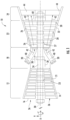
- FIG. 4 illustrates an isometric view of an exhaust diffuser assembly 100 having an exhaust diffuser 34 with a plurality of support link assemblies 300 coupled thereto.
- the exhaust diffuser 34 may include an inner liner 46, an outer liner 48, and a plurality of struts 44 extending (e.g., radially) between the inner liner 46 and the outer liner 48.
- the exhaust diffuser 34 may include a top half 70 and a bottom half 72, which are joined together at a split line 74. Additionally, the exhaust diffuser 34 may extend axially between a forward end 78 and an aft end 76.
- each support link assembly 300 in a group 310 of support link assemblies 300 may be approximately (e.g., ⁇ 5%) circumferentially equally spaced from the other support link(s) 300 in the group 310.
- each strut 44 of the plurality of struts 44 defines an interior 86 that extends between an outer opening 88 defined in the outer liner 48 and an inner opening 90 defined in the inner liner 46.
- the support link assemblies 300 that are affixed to the outer liner 48 may be disposed between circumferentially neighboring outer openings 88.
- one or more groups 310 may be disposed circumferentially between two neighboring outer openings 88.
- a single split-line support link assembly 300 may be disposed between the split line 74 and an outer opening 88 in closest proximity to the outer split-line 110.
- the circumferential groups 310 are shown as having three support link assemblies 300, other numbers of support link assemblies 300 may be used (e.g., two or more).
- the exhaust diffuser assembly 100 includes an outer liner 48 of an exhaust diffuser 34, a diffuser casing 56 radially spaced apart from the outer liner 48, and a support link assembly 300 coupling the outer liner 48 of the exhaust diffuser 34 to the diffuser casing 56.
- the diffuser casing 56 may include a casing body 104, a forward flange 106 extending radially outwardly from the casing body 104, and a tab 108 extending radially inwardly from the casing body 104.
- the forward flange 106 may couple to the aft flange 67 of the turbine casing 63 ( FIG. 2 ) when the exhaust diffuser assembly 100 is implemented in a gas turbine engine (such as the gas turbine engine 10 discussed above with reference to FIG. 1 ).
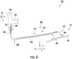
- the support link assembly 300 may include a support link 301 and a vibrational damping assembly 200 ( FIGS. 7-8 ) affixed to the support link 301.
- the support link 301 may include a main body 302, a forward flange 304, and a pair of aft arms 306 (one of which is shown in FIG. 5 ).
- the main body 302 may extend from a forward end 308 to an aft end 312.
- the forward flange 304 may extend (e.g., generally radially outwardly) from the main body 302 at the forward end 308 and couple (e.g., removably couple) to the diffuser casing 56.
- the forward flange 304 may couple to a forward face of the tab 108 of the diffuser casing 56 via one or more bolts 110.
- the aft arms 306 may extend (e.g., generally radially inwardly) from the main body 302 at the aft end 312.
- the aft arms 306 may be fixedly coupled to a radially outer surface of the outer liner 48 of the exhaust diffuser 34 (such as via welding, brazing, or other means).
- the aft arms 306 may form a weld joint 305 with an outer surface of the outer liner 48.
- FIG. 6 illustrates a perspective view a support link 301, which may be incorporated in the support link assemblies 300 discussed above with reference to FIGS. 2 through 5 .
- the vibrational damping assembly 200 as well as other mounting hardware has been removed from the support link assembly 300 to isolate the support link 301 in order to show details of the support link 301.
- the support link 301 includes the main body 302, the forward flange 304 at the forward end 308 of the main body 302, and the pair of aft arms 306 at the aft end 312 of the main body 302.
- the support link defines a longitudinal centerline 350 and a cartesian coordinate system relative to the longitudinal centerline 350 (e.g., a coordinate system having three directions mutually perpendicular to one another).
- the support link 301 defines a longitudinal direction L extending along the longitudinal centerline 350, a transverse direction T extending perpendicular to the longitudinal centerline 350, and a vertical direction V extending perpendicular to the longitudinal centerline 350.
- the longitudinal direction L, the transverse direction T, and the vertical direction V are mutually perpendicular.
- the aft portion 318 may extend to an aft edge 328 at the aft end 312, and the pair of arms 306 may extend from the aft portion 318 between the forward portion 316 and the aft edge 328.
- the forward portion 316 may be longer in the longitudinal direction L than the aft end 312, such as between about 1.5 times longer and about 5 times longer, or such as between about 2 times longer and about 4 times longer.
- the forward portion 316 may define a longitudinal length that is between about 150% and about 500% of a longitudinal length of the aft portion 318, or such as between about 200% and about 400%.
- the main body 302 may define a width 320 in the transverse direction T that varies in the longitudinal direction L between the forward end 308 and the aft end 312.
- the forward portion 316 converges in width 320 in the transverse direction T as the forward portion 316 extends longitudinally from the forward end 308 to the junction 317, such that the width 320 (e.g., the transverse width) of the forward portion 316 gradually decreases from the forward end 308 to the aft portion 318.
- the aft portion 318 may diverge in width 320 in the transverse direction T as the aft portion 318 extends longitudinally from the junction 317 with the forward portion 316 to the aft end 312, such that the width 320 (e.g., the transverse width) of the aft portion 316 increases from the junction 317 to the aft end 312.
- the junction 317 between the forward portion 316 and the aft portion 318 may be an inflection point at which the width 320 transitions from decreasing to increasing as the main body extends from the forward end 308 to the aft end 312.
- the forward flange 304 extends generally vertically from the main body in a first direction, and the pair of arms 306 each extend generally vertically from the main body 302 in a second direction that is opposite the first direction.
- the forward flange 304 may extend generally vertically outwardly from the main body 302, and the pair of arms 306 may each extend generally vertically inwardly from the main body 302.
- the forward flange 304 may include an arcuate segment 322 and a straight segment 324, and the forward flange 304 may extend to a terminal edge 326.
- the arcuate segment may extend between the forward end 308 of the main body 302 to the straight segment 324, and the straight segment 324 may extend from the arcuate segment 322 to the terminal edge 326.
- the arcuate segment 322 may increase in transverse width from the forward end 308 to the straight segment 324.
- the straight segment 324 may have a generally constant or uniform transverse width.
- the main body 302 may extend longitudinally between the forward end 308 and the aft end 312, and the main body 302 may extend transversely from a first side 330 to a second side 332.
- the main body 302 may be longer in the longitudinal direction L than the transverse direction T, e.g., a length between the forward end 308 and the aft end 312 may be longer than the width 320.
- the pair of arms 306 may include a first arm 307A and a second arm 307B spaced apart from the first arm 307A in the transverse direction T.
- the first arm 307A may extend from the first side 330 of the main body 302. More particularly, the first arm 307A may extend from the first side 330 of the main body 302 at the aft portion 318.
- the second arm 307B may extend from the second side 332 of the main body 302. That is, the second arm 307B may extend from the second side 332 of the main body 302 at the aft portion 318.
- the support link 301 may define one or more stress relief openings 334A, 334B.
- the one or more stress relief openings 334A, 334B may each include a hole 336A, 336B and a slit 338A, 338B extending from the hole to an edge of the support link 301.
- a first stress relief opening 334A may include a first hole 336A defined in the forward portion 316 of the main body 302 proximate the forward end 308.
- the first stress relief opening 334A may further include a first slit 338A extending from the first hole 336A to the terminal edge 326 of the forward flange 304.
- a majority portion of the first slit 338A may be defined in the forward flange 304, and a minority portion of the first slit 338A may be defined in the forward portion 316 of the main body 302.
- a second stress relief opening 334B may include a second hole 336B defined in the aft portion 318 of the main body 302.
- the second stress relief opening 334B may further include a second slit 338B extending from the second hole 336B to the aft edge 328.
- the forward flange 304 (such as the straight segment 324 of the forward flange 304) may define bolt holes 362 and dowel holes 364.
- the bolt holes 362 may be disposed on either side of the slit 338A.
- Each bolt hole 332 may be disposed between two dowel holes 364.
- the bolt holes 362 may be configured to receive a bolt
- the dowel holes 364 may be configured to receive a dowel rod to couple the forward flange to a diffuser casing.
- the bolt holes 362 may have a diameter that is larger than a diameter of the dowel holes 364.
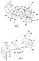
- FIG. 7 illustrates a perspective view of a first side of a support link 300
- FIG. 8 illustrates a perspective view of second side of the support link 300, in accordance with embodiments of the present disclosure.
- the support link 300 further includes a vibrational damping assembly 200 affixed to the support link 300.
- the vibrational damping assembly 200 may dampen vibrations experienced by the support link 301 during operation of the exhaust diffuser assembly 100 (and/or the gas turbine engine 10), in order to prevent damage to the support link 301 and increase the hardware life of the support link 301.
- the vibrational damping assembly 200 may include at least one plate 202 and at least one pin assembly 204 (shown more clearly in FIGS. 10-11 ) coupling the at least one plate 202 to the support link 301.
- the at least one pin assembly 204 may be coupled to the main body 302 of the support link 301.
- the at least one pin assembly 204 may include a pin 206 and a disk 208 coupled to the pin 206.
- the pin 206 may include a pin head 210 and a pin body 212.
- at least one plate 202 may be disposed between the pin head 210 and the support link 301.
- the at least one plate 202 surrounds the pin body 206 and is restricted to movement along the pin body 206 to dampen vibrations of the support link 301. That is, the at least one plate 202 is movable between the pin head 210 and the support link 301 relative to the pin 206 and relative to the support link 301 to dampen vibrations experienced by the support link 301.
- the vibrational damping assembly 200 further includes a brace 344 and one or more bands 346 coupled to the brace 344.
- brace 344 and the one or more bands 346 may collectively surround the main body 302 and the at least one plate 202.
- the support link 301 may include a first side surface 340 (such as an outer side surface) and a second side surface 342 (such as an inner side surface) opposite the first side surface 340.
- the brace 344 may extend along, and be disposed in contact with, the first side surface 340.
- At least one of the one or more plates 202 may be disposed along, and in contact with, the second side surface 342.
- the bands 346 may be coupled to the brace 344 and may extend along an exterior plate of the one or more plates 202.
- the first band portion 218 may couple to a first band 349 of the one or more bands 346
- the second band portion 220 may couple to the second band 347 of the one or more bands 346.
- FIG. 9 an enlarged view of the detail boxed in FIG. 7 is illustrated in accordance with exemplary aspects of the present disclosure. As should be appreciated, while FIG. 9 illustrates features of the first band portion 218 and the first band 349, the features illustrated in FIG. 9 may also be incorporated in the second band portion 222 and the second band 347.
- the first band portion 218 may include a plate segment 224 and two flange segments 226 extending perpendicularly from the plate segment 224 on either side 330, 332 of the main body 302.
- the plate segment 224 may be generally parallel to the main body 302 and in contact with the first surface 340 of the main body 302.
- the first band 349 may include a plate segment 228 and two tab segments 230 extending perpendicularly from the plate segment 228 on either side 330, 332 of the main body 302.
- Each flange segment 226 may include an inner surface 232 that is in contact with a side of the main body 302 (such as the first side 330 or the second side 332) and at least one plate of the one or more plates 202.
- each flange segment 226 may include an outer surface 234 that is in contact with an interior surface 236 of a tab segment 230.
- the tab segment 230 of the first band 349 may form a friction fit with the flange segment 226 of the first band portion 218 of the brace 344.
- FIG. 10 illustrates a cross sectional view of the support link assembly 300 from along the line 10-10 shown in FIG. 7 in accordance with embodiments of the present disclosure
- FIG. 11 illustrates an enlarged view of a portion of FIG. 10 . While FIG. 10 only illustrates the first arm 307A of the pair of arms 306, it should be understood and appreciated that the features shown and described with reference to FIG. 10 may also be incorporated into the second arm 307B.
- each arm 307A, 307B of the pair of arms 306 may extend from a root 352 connected the main body 302 to a free edge 354.
- the root 352 may be the junction between the main body 302 and the respective arm 307A, 307B.
- Each arm 307A, 307B may include a shank portion 356 and a protruding portion 358.
- the shank portion 356 may extend generally vertically from the root 352 to the protruding portion 358, and the protruding portion 358 may extend from the shank portion 356 to the free edge 354.
- the protruding portion 358 may extend outwardly (e.g., longitudinally and/or vertically) from the shank portion 356.
- the protruding portion 358 may include protrusions 360 that extend outwardly from the shank portion 356.
- the free edge 354 of each arm 307A, 307B may be welded to the outer liner 48, and the protrusions 360 may significantly reduce the stresses experienced at the weld joint as well as provide easier access to the junction to be welded, which is advantageous.
- the support link assembly 300 includes a support link 301 and a vibrational damping assembly 200 affixed to the support link 301.
- the vibrational damping assembly 200 may dampen vibrations experienced by the support link 301 during operation of the exhaust diffuser assembly 100 (and/or the gas turbine engine 10), in order to prevent damage to the support link 201 and increase the hardware life of the support link 301.
- the vibrational damping assembly 200 may include at least one plate 202, a brace 344, and at least one pin assembly 204 coupling the at least one plate 202 and the brace 344 to the support link 301.
- the at least one pin assembly 204 may be coupled to the main body 302 of the support link 301.
- the at least one pin assembly 204 may include a pin 206 and a disk 208 coupled to the pin 206.
- the pin may include a pin head 210 and a pin body 212.
- the pin head 210 may be disk shaped, may extend outwardly from the pin body 212 and may be generally parallel to the disk 208.
- the pin body 212 may extend through the at least one plate 202 (e.g., a first plate 240 and a second plate 242), the main body 302 of the support link 301, the brace 344, and the disk 208. Once installed, the pin 206 may be secured in position by welding or brazing the disk 208 to the pin body 212.
- At least one plate 202 may be disposed between the pin head 210 and the main body 302 of the support link 301.
- the at least one plate 202 surrounds the pin body 206 and is restricted to movement along the pin body 206 to dampen vibrations of the support link 301. That is, the at least one plate 202 is movable between the pin head 210 and the support link 301 relative to the pin 206 and relative to the support link 301 to dampen vibrations experienced by the support link 301.
- the at least one plate 202 (such as the first plate 240 and the second plate 242) may be disposed between the pin head 210 and the second side surface 342 of the main body 302.
- the brace 344 may be disposed between the disk 208 and the first side surface 340 of the main body 302.
- the plates 202 may include the first plate 242 having a first thickness 128 and the second plate 240 having a second thickness 129.
- the second thickness 129 may be greater than the first thickness 128.
- the second thickness 129 may be between about 20% and about 80% greater than the first thickness 128, or such as between about 30% and about 70% greater than the first thickness 128, or such as between about 40% and about 60% greater than the first thickness 128.
- the plates 202 may move relative to the support link 301 and one another, which causes micro-collisions (or "bumping") between the plates 202. These micro-collisions may counteract vibrations experienced by the support link 301 to which the vibrational damping assembly 200 is attached, thereby advantageously increasing the hardware life of the support link 301.
- the aft arms 306 of the support link 301 advantageously facilitate fixable coupling (e.g., welding) of the support link to the outer liner 48 without introducing unreasonable stresses at the weld location.
- a support link assembly for coupling an exhaust diffuser to a diffuser casing comprising: a support link comprising: a main body extending from a forward end to an aft end; a forward flange extending from the main body at the forward end, the forward flange configured to couple to the diffuser casing; and a pair of arms extending from the main body at the aft end, the pair of arms configured to couple to the exhaust diffuser.
- the vibrational damping assembly comprises: at least one pin assembly coupled to the main body of the support link, the at least one pin assembly having a pin and a disk, the pin including a pin head and a pin body; and at least one plate disposed between the pin head and the support link, wherein the at least one plate surrounds the pin body, and wherein the at least one plate is movable between the pin head and the support link relative to the pin and relative to the support link to dampen vibrations experienced by the support link.
- the vibrational damping assembly further comprises a brace and one or more bands coupled to the brace, wherein the brace and the one or more bands collectively surround the main body and the at least one plate.
- first band portion couples to a first band of the one or more bands
- second band portion couples to a second band of the one or more bands
- the main body includes a forward portion and an aft portion, wherein the forward portion converges in width as the forward portion extends from the forward end to a junction of the forward end with the aft portion, and wherein the aft portion diverges in width as the aft portion extends from the junction with the forward portion to the aft end.
Landscapes
- Engineering & Computer Science (AREA)
- Mechanical Engineering (AREA)
- General Engineering & Computer Science (AREA)
- Exhaust Silencers (AREA)
- Structures Of Non-Positive Displacement Pumps (AREA)
Applications Claiming Priority (1)
| Application Number | Priority Date | Filing Date | Title |
|---|---|---|---|
| PL44624323 | 2023-09-27 |
Publications (2)
| Publication Number | Publication Date |
|---|---|
| EP4530439A2 true EP4530439A2 (de) | 2025-04-02 |
| EP4530439A3 EP4530439A3 (de) | 2025-05-07 |
Family
ID=92633732
Family Applications (1)
| Application Number | Title | Priority Date | Filing Date |
|---|---|---|---|
| EP24197922.8A Pending EP4530439A3 (de) | 2023-09-27 | 2024-09-02 | Stützverbindung für eine abgasdiffusoranordnung |
Country Status (3)
| Country | Link |
|---|---|
| EP (1) | EP4530439A3 (de) |
| JP (1) | JP2025064941A (de) |
| CN (1) | CN119754877A (de) |
Family Cites Families (4)
| Publication number | Priority date | Publication date | Assignee | Title |
|---|---|---|---|---|
| US9476524B2 (en) * | 2012-08-15 | 2016-10-25 | United Technologies Corporation | Support system bumper for exhaust duct liner hanger |
| US9494109B2 (en) * | 2012-08-15 | 2016-11-15 | United Technologies Corporation | Pivoting ball stop for exhaust duct liner hanger |
| US10533457B2 (en) * | 2017-05-11 | 2020-01-14 | United Technologies Corporation | Exhaust liner cable fastener |
| US10458281B2 (en) * | 2017-06-12 | 2019-10-29 | United Technologies Corporation | Resilient mounting assembly for a turbine engine |
-
2024
- 2024-08-22 CN CN202411163854.1A patent/CN119754877A/zh active Pending
- 2024-08-29 JP JP2024147491A patent/JP2025064941A/ja active Pending
- 2024-09-02 EP EP24197922.8A patent/EP4530439A3/de active Pending
Also Published As
| Publication number | Publication date |
|---|---|
| CN119754877A (zh) | 2025-04-04 |
| JP2025064941A (ja) | 2025-04-17 |
| EP4530439A3 (de) | 2025-05-07 |
Similar Documents
| Publication | Publication Date | Title |
|---|---|---|
| JP7638676B2 (ja) | ターボ機械ロータブレード用のダンパスタック | |
| US12281586B2 (en) | Vibrational damping assembly for use in an airfoil | |
| US9273868B2 (en) | System for supporting bundled tube segments within a combustor | |
| EP3220051A1 (de) | Gebündelte rohrbrennstoffdüse mit vibrationsdämpfung | |
| US11248475B2 (en) | Damper stacks for turbomachine rotor blades | |
| US11767766B1 (en) | Turbomachine airfoil having impingement cooling passages | |
| US11371699B2 (en) | Integrated front panel for a burner | |
| US11739645B2 (en) | Vibrational dampening elements | |
| US20140318140A1 (en) | Premixer assembly and mechanism for altering natural frequency of a gas turbine combustor | |
| EP4530439A2 (de) | Stützverbindung für eine abgasdiffusoranordnung | |
| EP4239167A1 (de) | Abgasfrequenzminderungsvorrichtung | |
| EP3309457A1 (de) | Verbrennungsdynamik-abschwächungssystem | |
| US20250109696A1 (en) | Gas Turbine Exhaust Diffuser Horizontal Split Configuration | |
| EP4506539A1 (de) | Schwingungsdämpfungsanordnung für einen turbomaschinenabgasdiffusor | |
| US11773750B2 (en) | Turbomachine component retention | |
| US11774099B2 (en) | Gas turbine fuel nozzle tip comprising an impingement wall | |
| EP4509699A1 (de) | Hinterkantenkühlkreislauf für turbomaschinenschaufel |
Legal Events
| Date | Code | Title | Description |
|---|---|---|---|
| PUAI | Public reference made under article 153(3) epc to a published international application that has entered the european phase |
Free format text: ORIGINAL CODE: 0009012 |
|
| STAA | Information on the status of an ep patent application or granted ep patent |
Free format text: STATUS: THE APPLICATION HAS BEEN PUBLISHED |
|
| AK | Designated contracting states |
Kind code of ref document: A2 Designated state(s): AL AT BE BG CH CY CZ DE DK EE ES FI FR GB GR HR HU IE IS IT LI LT LU LV MC ME MK MT NL NO PL PT RO RS SE SI SK SM TR |
|
| PUAL | Search report despatched |
Free format text: ORIGINAL CODE: 0009013 |
|
| AK | Designated contracting states |
Kind code of ref document: A3 Designated state(s): AL AT BE BG CH CY CZ DE DK EE ES FI FR GB GR HR HU IE IS IT LI LT LU LV MC ME MK MT NL NO PL PT RO RS SE SI SK SM TR |
|
| RIC1 | Information provided on ipc code assigned before grant |
Ipc: F01D 25/30 20060101ALI20250328BHEP Ipc: F01D 25/28 20060101ALI20250328BHEP Ipc: F01D 25/24 20060101ALI20250328BHEP Ipc: F01D 25/04 20060101ALI20250328BHEP Ipc: F01D 25/00 20060101AFI20250328BHEP |
|
| RAP3 | Party data changed (applicant data changed or rights of an application transferred) |
Owner name: GE VERNOVA TECHNOLOGY GMBH |
|
| STAA | Information on the status of an ep patent application or granted ep patent |
Free format text: STATUS: REQUEST FOR EXAMINATION WAS MADE |
|
| 17P | Request for examination filed |
Effective date: 20250929 |