EP4530405A1 - Air flow device and handheld hair dryer - Google Patents
Air flow device and handheld hair dryer Download PDFInfo
- Publication number
- EP4530405A1 EP4530405A1 EP23851597.7A EP23851597A EP4530405A1 EP 4530405 A1 EP4530405 A1 EP 4530405A1 EP 23851597 A EP23851597 A EP 23851597A EP 4530405 A1 EP4530405 A1 EP 4530405A1
- Authority
- EP
- European Patent Office
- Prior art keywords
- fan
- equal
- airflow device
- assembly
- guide vane
- Prior art date
- Legal status (The legal status is an assumption and is not a legal conclusion. Google has not performed a legal analysis and makes no representation as to the accuracy of the status listed.)
- Pending
Links
Images















Classifications
-
- F—MECHANICAL ENGINEERING; LIGHTING; HEATING; WEAPONS; BLASTING
- F04—POSITIVE - DISPLACEMENT MACHINES FOR LIQUIDS; PUMPS FOR LIQUIDS OR ELASTIC FLUIDS
- F04D—NON-POSITIVE-DISPLACEMENT PUMPS
- F04D29/00—Details, component parts, or accessories
- F04D29/40—Casings; Connections of working fluid
- F04D29/403—Casings; Connections of working fluid especially adapted for elastic fluid pumps
-
- A—HUMAN NECESSITIES
- A01—AGRICULTURE; FORESTRY; ANIMAL HUSBANDRY; HUNTING; TRAPPING; FISHING
- A01G—HORTICULTURE; CULTIVATION OF VEGETABLES, FLOWERS, RICE, FRUIT, VINES, HOPS OR SEAWEED; FORESTRY; WATERING
- A01G20/00—Cultivation of turf, lawn or the like; Apparatus or methods therefor
- A01G20/40—Apparatus for cleaning the lawn or grass surface
- A01G20/43—Apparatus for cleaning the lawn or grass surface for sweeping, collecting or disintegrating lawn debris
- A01G20/47—Vacuum or blower devices
-
- E—FIXED CONSTRUCTIONS
- E01—CONSTRUCTION OF ROADS, RAILWAYS, OR BRIDGES
- E01H—STREET CLEANING; CLEANING OF PERMANENT WAYS; CLEANING BEACHES; DISPERSING OR PREVENTING FOG IN GENERAL CLEANING STREET OR RAILWAY FURNITURE OR TUNNEL WALLS
- E01H1/00—Removing undesirable matter from roads or like surfaces, with or without moistening of the surface
- E01H1/08—Pneumatically dislodging or taking-up undesirable matter or small objects; Drying by heat only or by streams of gas; Cleaning by projecting abrasive particles
- E01H1/0809—Loosening or dislodging by blowing ; Drying by means of gas streams
-
- E—FIXED CONSTRUCTIONS
- E01—CONSTRUCTION OF ROADS, RAILWAYS, OR BRIDGES
- E01H—STREET CLEANING; CLEANING OF PERMANENT WAYS; CLEANING BEACHES; DISPERSING OR PREVENTING FOG IN GENERAL CLEANING STREET OR RAILWAY FURNITURE OR TUNNEL WALLS
- E01H1/00—Removing undesirable matter from roads or like surfaces, with or without moistening of the surface
- E01H1/08—Pneumatically dislodging or taking-up undesirable matter or small objects; Drying by heat only or by streams of gas; Cleaning by projecting abrasive particles
- E01H1/0863—Apparatus loosening or removing the dirt by blowing and subsequently dislodging it at least partially by suction ; Combined suction and blowing nozzles
-
- F—MECHANICAL ENGINEERING; LIGHTING; HEATING; WEAPONS; BLASTING
- F04—POSITIVE - DISPLACEMENT MACHINES FOR LIQUIDS; PUMPS FOR LIQUIDS OR ELASTIC FLUIDS
- F04D—NON-POSITIVE-DISPLACEMENT PUMPS
- F04D19/00—Axial-flow pumps
- F04D19/002—Axial flow fans
-
- F—MECHANICAL ENGINEERING; LIGHTING; HEATING; WEAPONS; BLASTING
- F04—POSITIVE - DISPLACEMENT MACHINES FOR LIQUIDS; PUMPS FOR LIQUIDS OR ELASTIC FLUIDS
- F04D—NON-POSITIVE-DISPLACEMENT PUMPS
- F04D25/00—Pumping installations or systems
- F04D25/02—Units comprising pumps and their driving means
- F04D25/06—Units comprising pumps and their driving means the pump being electrically driven
-
- F—MECHANICAL ENGINEERING; LIGHTING; HEATING; WEAPONS; BLASTING
- F04—POSITIVE - DISPLACEMENT MACHINES FOR LIQUIDS; PUMPS FOR LIQUIDS OR ELASTIC FLUIDS
- F04D—NON-POSITIVE-DISPLACEMENT PUMPS
- F04D25/00—Pumping installations or systems
- F04D25/02—Units comprising pumps and their driving means
- F04D25/06—Units comprising pumps and their driving means the pump being electrically driven
- F04D25/0673—Battery powered
-
- F—MECHANICAL ENGINEERING; LIGHTING; HEATING; WEAPONS; BLASTING
- F04—POSITIVE - DISPLACEMENT MACHINES FOR LIQUIDS; PUMPS FOR LIQUIDS OR ELASTIC FLUIDS
- F04D—NON-POSITIVE-DISPLACEMENT PUMPS
- F04D25/00—Pumping installations or systems
- F04D25/02—Units comprising pumps and their driving means
- F04D25/08—Units comprising pumps and their driving means the working fluid being air, e.g. for ventilation
- F04D25/084—Units comprising pumps and their driving means the working fluid being air, e.g. for ventilation hand fans
-
- F—MECHANICAL ENGINEERING; LIGHTING; HEATING; WEAPONS; BLASTING
- F04—POSITIVE - DISPLACEMENT MACHINES FOR LIQUIDS; PUMPS FOR LIQUIDS OR ELASTIC FLUIDS
- F04D—NON-POSITIVE-DISPLACEMENT PUMPS
- F04D29/00—Details, component parts, or accessories
- F04D29/26—Rotors specially for elastic fluids
- F04D29/32—Rotors specially for elastic fluids for axial flow pumps
- F04D29/325—Rotors specially for elastic fluids for axial flow pumps for axial flow fans
-
- F—MECHANICAL ENGINEERING; LIGHTING; HEATING; WEAPONS; BLASTING
- F04—POSITIVE - DISPLACEMENT MACHINES FOR LIQUIDS; PUMPS FOR LIQUIDS OR ELASTIC FLUIDS
- F04D—NON-POSITIVE-DISPLACEMENT PUMPS
- F04D29/00—Details, component parts, or accessories
- F04D29/40—Casings; Connections of working fluid
- F04D29/52—Casings; Connections of working fluid for axial pumps
- F04D29/54—Fluid-guiding means, e.g. diffusers
- F04D29/541—Specially adapted for elastic fluid pumps
- F04D29/542—Bladed diffusers
- F04D29/544—Blade shapes
-
- F—MECHANICAL ENGINEERING; LIGHTING; HEATING; WEAPONS; BLASTING
- F04—POSITIVE - DISPLACEMENT MACHINES FOR LIQUIDS; PUMPS FOR LIQUIDS OR ELASTIC FLUIDS
- F04D—NON-POSITIVE-DISPLACEMENT PUMPS
- F04D29/00—Details, component parts, or accessories
- F04D29/40—Casings; Connections of working fluid
- F04D29/52—Casings; Connections of working fluid for axial pumps
- F04D29/54—Fluid-guiding means, e.g. diffusers
- F04D29/541—Specially adapted for elastic fluid pumps
- F04D29/545—Ducts
-
- F—MECHANICAL ENGINEERING; LIGHTING; HEATING; WEAPONS; BLASTING
- F04—POSITIVE - DISPLACEMENT MACHINES FOR LIQUIDS; PUMPS FOR LIQUIDS OR ELASTIC FLUIDS
- F04D—NON-POSITIVE-DISPLACEMENT PUMPS
- F04D29/00—Details, component parts, or accessories
- F04D29/66—Combating cavitation, whirls, noise, vibration or the like; Balancing
- F04D29/68—Combating cavitation, whirls, noise, vibration or the like; Balancing by influencing boundary layers
- F04D29/681—Combating cavitation, whirls, noise, vibration or the like; Balancing by influencing boundary layers especially adapted for elastic fluid pumps
- F04D29/682—Combating cavitation, whirls, noise, vibration or the like; Balancing by influencing boundary layers especially adapted for elastic fluid pumps by fluid extraction
-
- F—MECHANICAL ENGINEERING; LIGHTING; HEATING; WEAPONS; BLASTING
- F04—POSITIVE - DISPLACEMENT MACHINES FOR LIQUIDS; PUMPS FOR LIQUIDS OR ELASTIC FLUIDS
- F04D—NON-POSITIVE-DISPLACEMENT PUMPS
- F04D29/00—Details, component parts, or accessories
- F04D29/66—Combating cavitation, whirls, noise, vibration or the like; Balancing
- F04D29/68—Combating cavitation, whirls, noise, vibration or the like; Balancing by influencing boundary layers
- F04D29/681—Combating cavitation, whirls, noise, vibration or the like; Balancing by influencing boundary layers especially adapted for elastic fluid pumps
- F04D29/684—Combating cavitation, whirls, noise, vibration or the like; Balancing by influencing boundary layers especially adapted for elastic fluid pumps by fluid injection
-
- F—MECHANICAL ENGINEERING; LIGHTING; HEATING; WEAPONS; BLASTING
- F05—INDEXING SCHEMES RELATING TO ENGINES OR PUMPS IN VARIOUS SUBCLASSES OF CLASSES F01-F04
- F05D—INDEXING SCHEME FOR ASPECTS RELATING TO NON-POSITIVE-DISPLACEMENT MACHINES OR ENGINES, GAS-TURBINES OR JET-PROPULSION PLANTS
- F05D2250/00—Geometry
- F05D2250/10—Two-dimensional
- F05D2250/19—Two-dimensional machined; miscellaneous
- F05D2250/191—Two-dimensional machined; miscellaneous perforated
Definitions
- an airflow device By rotating fan blades, an airflow device drives gas to flow to do work, thereby implementing the main function of the airflow device.
- the airflow device may be a blower, a blow-suction machine, or the like.
- the blower is widely used in gardens, streets, homes, and other environments.
- the noise of the airflow device is affected by many factors, and the noise may further increase when the flow rate of the blown gas increases.
- users have higher requirements on the noise generated by the airflow device in operation.
- At least one of the multiple through holes is basically circular, and the hole diameter D3 of the multiple through holes is greater than or equal to 2 mm and less than or equal to 5 mm.
- the fan blade support portion 253 supports the fan blades 252, and the hub ratio is defined as the ratio of the maximum first diameter formed by the fan blade support portion to the second diameter formed by the outermost edges of the fan blades, where the hub ratio is greater than or equal to 0.4 and less than or equal to 0.5.
- the first distance L1 is formed between a guide vane root of the guide vane and the fan blade, where the first distance is greater than or equal to 5 mm and less than or equal to 30 mm.
- a guide vane root of the guide vane intersects with a guide vane support portion
- the fan assembly includes a fan front end located on the front side and a fan rear end located on the rear side
- the guide vane support portion includes a first rear edge located on the rear side
- the second distance L2 is defined as the distance between the fan front end of the fan assembly and the first rear edge of the guide vane support portion, where the second distance is greater than or equal to 3 mm and less than or equal to 6 mm.
- the radial thickness L3 of the guide vane is greater than or equal to 9 mm and less than or equal to 15 mm.
- an opening rate of the guide vane is defined as the ratio of the total opening area of the guide vane to the total radial area of the guide vane, where the opening rate is greater than or equal to 10% and less than or equal to 75%.
- the ratio T/D of the average wall thickness T of the pipe assembly to the inner diameter D of the pipe assembly is greater than or equal to 1:50 and less than or equal to 1:15.
- the airflow device is a blower, a blow-suction machine, or another device that performs work through the airflow.
- An airflow device includes a grip for a user to hold; a pipe assembly for the air to pass through; a fan assembly including fan blades and a fan blade support portion supporting the fan blades, where the fan blades are rotatable about a fan axis, and the fan assembly is an axial flow fan; a motor for driving the fan assembly to rotate; and guide vanes for directing the airflow.
- the inner diameter of the pipe assembly is greater than or equal to 90 mm.
- the flow rate of the airflow device is greater than or equal to 1000 CFM.
- the maximum rotational speed of the motor is less than 35000 rpm.
- the first distance is formed between a guide vane root of the guide vane and the fan blade, where the first distance is greater than or equal to 5 mm and less than or equal to 30 mm.
- the first distance is formed between a guide vane root of the guide vane and the fan blade, where the first distance is greater than or equal to 5 mm and less than or equal to 20 mm.
- the pipe assembly includes a first pipe and a second pipe, where the first pipe is located on the front side of the second pipe.
- the average wall thickness of the pipe assembly is greater than or equal to 3 mm.
- the hub ratio is defined as the ratio of the maximum first diameter formed by the fan blade support portion to the second diameter formed by the outermost edges of the fan blades, where the hub ratio is greater than or equal to 0.4 and less than or equal to 0.5.
- a guide vane root of the guide vane intersects with a guide vane support portion
- the fan assembly includes a fan front end located on the front side and a fan rear end located on the rear side
- the guide vane support portion includes a first rear edge located on the rear side
- the second distance L2 is defined as the distance between the fan front end of the fan assembly and the first rear edge of the guide vane support portion, where the second distance is greater than or equal to 3 mm and less than or equal to 6 mm.
- the airflow device includes a body, where the body includes the fan assembly, the motor, and a housing, and the housing is formed with the grip; the airflow device further includes a wind tube, the wind tube is detachably connected to the body, and the wind tube allows the air to pass through; the airflow device is provided with an ejection mechanism, and the ejection mechanism applies an ejection force so that the wind tube tends to be separated from the body.
- the airflow device includes a battery pack coupling portion configured to mount a battery pack for supplying power to the airflow device.
- the airflow device is a blower, a blow-suction machine, or another device that performs work through the airflow.
- the airflow device further includes a handle used for the user to hold and located on the front side of the grip.
- guide vanes for directing the airflow are further included, where the guide vane includes multiple through holes penetrating at least part of the guide vane.
- an opening rate of the guide vane is defined as the ratio of the total opening area of the guide vane to the total radial area of the guide vane, where the opening rate is greater than or equal to 10% and less than or equal to 75%.
- the ratio T/D of the average wall thickness T of the pipe assembly to the inner diameter D of the pipe assembly is greater than or equal to 1:50 and less than or equal to 1:15.
- the airflow device is capable of being connected to a belt for use, a blower is provided with a belt coupling portion, the belt is provided with a belt mounting portion, and the belt coupling portion and the belt mounting portion are assembled so that the belt is mounted to the blower.
- An airflow device includes a grip for a user to hold; a pipe assembly for the air to pass through; a fan assembly including fan blades and a fan blade support portion supporting the fan blades, where the fan blades are rotatable about a fan axis of the fan assembly, and the fan assembly is an axial flow fan; and a motor for driving the fan assembly to rotate.
- the airflow device further includes a handle used for the user to hold and located on the front side of the grip, the flow rate of the airflow device is greater than or equal to 1000 CFM, and the maximum rotational speed of the motor is less than 35000 rpm.
- guide vanes for directing the airflow are further included, where along the direction of the fan axis, the first distance is formed between a guide vane root of the guide vane and the fan blade, where the first distance is greater than or equal to 5 mm and less than or equal to 20 mm.
- An airflow device includes a grip for a user to hold; a pipe assembly for the air to pass through; a fan assembly including fan blades and a fan blade support portion supporting the fan blades, where the fan blades are rotatable about a fan axis, and the fan assembly is an axial flow fan; a motor for driving the fan assembly to rotate; and guide vanes for directing the airflow.
- the hub ratio is defined as the ratio of the maximum first diameter D1 formed by the fan blade support portion to the second diameter D2 formed by the outermost edges of the fan blades, where the hub ratio is less than or equal to 0.5.
- the maximum rotational speed of the motor is less than 30000 rpm.
- the inner diameter of the pipe assembly is greater than or equal to 90 mm.
- the flow rate of the airflow device is greater than or equal to 1000 CFM.
- a guide vane includes multiple through holes penetrating at least part of the guide vane.
- the first distance L1 is formed between a guide vane root of a guide vane and the fan blade, where the first distance is greater than or equal to 5 mm and less than or equal to 30 mm.
- a guide vane root of a guide vane intersects with a guide vane support portion
- the fan assembly includes a fan front end located on the front side and a fan rear end located on the rear side
- the guide vane support portion includes a first rear edge located on the rear side
- the second distance L2 is defined as the distance between the fan front end of the fan assembly and the first rear edge of the guide vane support portion, where the second distance is greater than or equal to 3 mm and less than or equal to 6 mm.
- the average wall thickness of the pipe assembly is greater than or equal to 3 mm.
- An airflow device includes a grip for a user to hold; a pipe assembly for the air to pass through; fan blades rotatable about a fan axis; a motor for driving the fan assembly to rotate; and guide vanes for directing the airflow.
- the average wall thickness T of the pipe assembly is greater than 3 mm.
- the product T*D of the average wall thickness T of the pipe assembly and the inner diameter D of the pipe assembly is greater than or equal to 2700 mm ⁇ mm, and the ratio T/D of the average wall thickness T of the pipe assembly to the inner diameter D of the pipe assembly is greater than or equal to 1:50 and less than or equal to 1:15.
- the flow rate of the airflow device is greater than or equal to 1000 CFM.
- the inner diameter of the pipe assembly is greater than or equal to 90 mm.
- the maximum rotational speed of the motor is less than 30000 rpm.
- the average wall thickness T of the pipe assembly is greater than or equal to 3.5 mm.
- a conical pipe is formed inside the pipe assembly, the conical pipe extends from a first end located on the front side of the pipe assembly, the conical pipe accommodates at least part of the motor, the distance by which the conical pipe extends from the first end is the fourth distance L4, the guide vane includes a third end facing the fan blade and a fourth end facing away from the fan blade, the distance from the fourth end to the first end is the fifth distance L5, and the ratio L4/L5 of the fourth distance to the fifth distance is greater than or equal to 0 and less than or equal to 0.1.
- a conical pipe is formed inside the pipe assembly, the conical pipe extends from a first end located on the front side of the pipe assembly, the conical pipe accommodates at least part of the motor, the guide vane includes a third end facing the fan blade and a fourth end facing away from the fan blade, the distance from the fourth end to the first end is the fifth distance L5, and the fifth distance is approximately 0.
- the airflow device includes a battery pack coupling portion configured to mount a battery pack for supplying power to the airflow device.
- the airflow device is a blower, a blow-suction machine, or another device that performs work through the airflow.
- An airflow device includes a grip for a user to hold; a pipe assembly for the air to pass through; a fan assembly including fan blades and a fan blade support portion supporting the fan blades, where the fan blades are rotatable about a fan axis of the fan assembly; and a motor for driving the fan assembly to rotate.
- the airflow device further includes a handle used for the user to hold and located on the front side of the grip, and the air volume of the airflow device is greater than 1000 CFM.
- the handle is rotatable about a handle axis, the angle of rotation of the handle is ⁇ , and the angle of rotation ⁇ is greater than 10 degrees and less than or equal to 150 degrees.
- the handle has at least one lockable position.
- a housing is further included, where the pipe assembly is connected to the housing, and the handle is detachably connected to the housing.
- a housing and a mounting assembly are further included, where the handle is mounted to the housing through the mounting assembly, and the mounting assembly enables the handle to rotate about a handle axis and enables the handle to be locked at any angle during a rotation process.
- the mounting assembly includes a trigger, a rotary shaft, and a fastener
- the rotary shaft passes through the housing and the handle
- the fastener is detachably connected to an end of the rotary shaft
- the trigger is hinged to the other end of the rotary shaft
- the trigger is rotatable relative to the rotary shaft so that the trigger has a locking position and an unlocking position, where when the trigger is at the locking position, the handle is clamped between the fastener and the trigger, and when the trigger is at the unlocking position, the handle is rotatable relative to the rotary shaft.
- an illumination device disposed on the front side of the handle is further included.
- the inner diameter of the pipe assembly is D
- the width of the handle along the left and right direction is W
- W/D is greater than or equal to 1 and less than or equal to 2.5.
- the looped portion has a first height M1 along the up and down direction
- the shielding portion has a first length M3 along the left and right direction, where the first length M3 is greater than or equal to the first height M1.
- the airflow device may be a fan.
- the airflow device may be a blower, a blow-suction machine, or another device that needs to blow or suck the airflow to do work.
- the blower accelerates the air through the rotation of the fan and pushes an object to be moved through the airflow.
- the blow-suction machine has two functions: blowing and suction so that the blow-suction machine can push the object through the airflow and suck the object through the airflow.
- the blower and the blow-suction machine are often used in fields such as garden cleaning.
- blower 10 The technical solution of the present application is described below using a blower 10 as an example.
- the blower 10 includes a housing 100, a blow-suction structure 200, and a power supply system.
- the housing 100 forms an accommodation space that can accommodate at least part of the blow-suction structure 200, and the housing 100 is formed with or connected to a grip 150 for the user to hold.
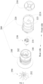
- the blow-suction structure 200 includes functional assemblies for implementing blowing and suction functions, such as a motor 230, a fan assembly 250, and guide vanes 282.
- the blow-suction structure 200 further includes a pipe assembly 260 for fixing and accommodating the preceding functional assemblies and providing a channel for the airflow.
- a vent cover 300 is used for sucking air into the blow-suction structure 200. In this example, the vent cover 300 is grid-shaped.
- the housing 100 connects and fixes the vent cover 300 to the blow-suction structure 200. Air is sucked into the blower 10 through the vent cover 300 and driven by the fan assembly 250 in the blow-suction structure 200 to be blown out from a first end 201 of the blow-suction structure 200.
- the first bracket 112 and the second bracket 122 support the blow-suction structure 200 so that the blower 10 does not fall over.
- the grip 150 may be provided independently of the housing 100, that is to say, the grip 150 may not be formed by extending from the housing 100.
- the pipe assembly 260 is connected to the housing 100, and at least part of the pipe assembly 260 is wrapped and/or fixed by the housing 100.
- the pipe assembly 260 is used for the air to pass through and includes a first end 201 and a second end 202. At least part of the airflow flows between the first end 201 and the second end 202.
- the rotation of the motor 230 drives fan blades 252 to rotate so that the air outside the blower 10 enters the second end 202 of the pipe assembly 260 from the vent cover 300, flows through the fan blades 252, the guide vanes 282, and a conical pipe 223 in sequence, and finally flows out from the first end 201 of the pipe assembly 260.
- the blow-suction machine when the blow-suction machine is in a suction mode, the airflow flows in a direction opposite to that in the preceding blower.
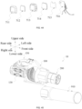
- the fan assembly 250 includes fan blades 252 and a fan blade support portion 253, and the fan blades 252 are mounted on the fan blade support portion 253 or integrally formed with the fan blade support portion 253.
- the fan blades 252 are rotatable about a fan axis 251.
- the fan assembly 250 may be an axial flow fan or a centrifugal fan.
- the motor 230 includes a motor output shaft 232, the motor output shaft 232 extends along a motor axis 231, and the fan axis 251 of the fan blades 252 basically coincides with the motor axis 231.
- a rear end 254 (referring to FIG. 7 ) of the fan assembly 250 has a hollow structure inside.
- the motor output shaft 232 extends into the fan blade support portion 253 of the fan assembly 250.
- the motor output shaft 232 and the fan assembly 250 are fixed by screws.
- FIG. 4 and FIGS. 9 to 14 disclose the structures of a second pipe 240 and the guide vanes 282 therein.
- the pipe assembly 260 includes a first pipe 220 and a second pipe 240.
- the guide vanes 282 include first guide vanes 242 and second guide vanes 222.
- the first guide vanes 242 are located in the second pipe 240, and the second guide vanes 222 are located in the first pipe 220.
- the blower 10 further includes a guide vane support portion 281 for supporting the guide vanes 282.
- the guide vane support portion 281 includes a first guide vane support portion 241 and a second guide vane support portion 221.
- the first guide vane support portion 241 supports the first guide vanes 242, and the second guide vane support portion 221 supports the second guide vanes 222.
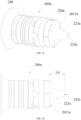
- a guide vane root 2431 of the first guide vane 242 is located on the first guide vane support portion 241, and the first guide vane 242 connects the first guide vane support portion 241 to an outer housing of the second pipe 240.
- three first guide vanes 242 are disposed on the first guide vane support portion 241.
- the first guide vane support portion 241 forms an accommodation space for accommodating at least part of the motor 230.
- the screw passes through a mounting hole 246 to fix the motor 230 into the second pipe 240.
- a guide vane axis 249 passes through the center of the first guide vane 242.
- the first guide vanes 242 are arranged at intervals in the circumferential direction of the guide vane axis 249.
- the first guide vanes 242 and the first guide vane support portion 241 extend basically along the radial direction of the guide vane axis 249.
- the pipe assembly 260 further includes a protective cover 210, and the protective cover 210 is not the guide vane 282.
- the protective cover 210 is disposed at the frontmost side of the conical pipe 223 and may be used for reminding the operator not to put hands into the blower 10.
- four ribs are provided on the protective cover 210, and three guide vanes 282 are provided.
- the guide vanes 282 are disposed between the fan blades 252 and the protective cover 210, and the guide vanes 282 are disposed between the fan blades 252 and the conical pipe 223.
- the second guide vane support portion 221 extends forward and is connected to the conical pipe 223.
- the guide vanes 282 surround and support the conical pipe 223.
- the airflow flows in through the vent cover 300 of the second end 202 of the blower 10 and is accelerated by the fan blades 252
- the airflow is guided by the guide vanes 282 to flow along the outer wall of the conical pipe 223 to an air port 2231 on the front side of the conical pipe 223.
- a part of the airflow passes through the protective cover 210 and flows out from the second end 201 of the blower 10, and the other part of the airflow flows back from the air port 2231 to the motor 230 to help the motor dissipate heat.
- the first guide vane 242 includes multiple through holes 243 penetrating at least part of the first guide vane 242.
- each first guide vane 242 is provided with multiple through holes 243.
- the radial thickness L3 of the first guide vane 242 is greater than or equal to 9 mm and less than or equal to 15 mm. In an example, the radial thickness L3 is about 11 mm. In an example, the radial thickness L3 is about 13 mm.
- At least one of the multiple through holes 242 is basically circular, and the hole diameter D3 of each of the multiple through holes 242 is greater than or equal to 2 mm and less than or equal to 5 mm.
- the hole diameter D3 is about 2.5 mm.
- the hole diameter D3 is about 3 mm.
- the hole diameter D3 is about 3.5 mm.
- the hole diameter D3 is about 4 mm.
- the shapes of the multiple through holes 243 are not limited as long as the fluid such as air can pass through the inside of the multiple through holes 243.
- basically circular includes both a circle in the geometric sense and an ellipse with a ratio of the major axis length to the minor axis length being between 0.9 and 1.1.
- the multiple through holes 243 penetrates the first guide vane 242 along a through hole axis 2432, and the through hole axis 2432 is basically parallel to the fan axis 251 of the fan assembly 250. Since the fan axis 251 is basically parallel to the guide vane axis 249, the through hole axis 2432 is also basically parallel to the guide vane axis 249.
- the "punching direction" of the multiple through holes 243 is basically consistent with the motion direction of the fluid such as air.
- the multiple through holes 243 penetrate the first guide vane 242 along through hole axes 2432, and the through hole axes 2432 are basically parallel to the fan axis 251 of the fan assembly 250.
- the through hole axes 2432 are also basically parallel to the guide vane axis 249 and the fan axis 251.
- the through hole axes 2432 of the multiple through holes 243 may form an included angle with the guide vane axis 249, and the included angle is greater than 0 degrees and less than or equal to 50 degrees. Within this angle range, the multiple through holes 243 guide the flow direction of the fluid to a certain extent, thereby reducing the vibration and noise generated when the fluid "collides" with the first guide vanes 242.
- the included angle may be 10 degrees, 20 degrees, or 30 degrees.
- basically parallel includes both absolute parallelism of two axes in the geometric sense and a state in which the included angle between the two axes is relatively small, such as a state in which the included angle between the two axes is within 10 degrees.
- the first guide vane 242 includes at least a first surface 2421 and a second surface 2422.
- the first surface 2421 is an outwardly convex surface
- the second surface 2422 is an inwardly concave surface.
- the opening rate of the first guide vane 242 is defined as the ratio of the total opening area of the first guide vane 242 to the total area of the first guide vane 242, and the opening rate is greater than or equal to 10% and less than or equal to 75%. In an example, the opening rate is greater than or equal to 20% and less than or equal to 50%. In an example, the opening rate may be 25%, 30%, or 40%.
- Limiting the range of the opening rate is equivalent to limiting the proportion of the fluid that can flow through the inside of the first guide vane 242 so that while the guiding capability of the first guide vane 242 is not greatly reduced, the degree of the impact between the fluid and the first surface 2421 of the first guide vane 242 can be reduced, thereby reducing the vibration and noise.
- the space formed between two adjacent guide vanes 282 is not the multiple through holes 243 mentioned in the present application, and the multiple through holes 243 are formed on the same guide vane 282.
- the opening rate is also for the same guide vane 282.
- different guide vanes 282 on the same blower 10 may have different opening rates, and different guide vanes 282 on the same blower 10 may have different through-hole shapes.
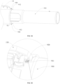
- FIG. 5 is a partial enlarged view of FIG. 4 .
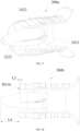
- the first distance L1 is formed between the guide vane root 2431 of the first guide vane 242 and the fan blade 252, where the first distance L1 is greater than or equal to 5 mm and less than or equal to 30 mm.
- the guide vane root 2431 refers to the rearmost side of the intersection of the first guide vane 242 and the first guide vane support portion 241. As shown in FIG.
- a projection of the guide vane root 2431 on the fan blade 252 along the direction of the guide vane axis 249 is a first point 2521 on the fan blade 252, and the distance between the guide vane root 2431 and the first point 2521 is the first distance L1.
- the first distance L1 is greater than or equal to 5 mm and less than or equal to 30 mm. In an example, the first distance L1 is greater than or equal to 5 mm and less than or equal to 20 mm. In an example, the first distance L1 is greater than or equal to 20 mm and less than or equal to 30 mm. In some examples, the first distance L1 is about 100 mm, 15 mm, or 20 mm.
- the distance set between the first guide vane 242 and the fan blade 252 can make the fluid flow from the fan blade 252 to the first guide vane 242 at a more appropriate speed and impact force, and the vibration and noise generated when the fluid "collides" with the first guide vane 242 are not too large. If the first distance L1 is greater than 30 mm, the distance between the fan blade 252 and the first guide vane 242 is too large, affecting the flow guiding effect of the first guide vane 242. If the first distance L1 is less than 5 mm, the distance between the fan blade 252 and the first guide vane 242 is too small, and the vibration and noise generated by the airflow are relatively large.
- the fan assembly 250 includes a fan front end 255 located on the front side and a fan rear end 254 located on the rear side, and the first guide vane support portion 241 includes a first rear edge 248 located on the rear side (referring to FIG. 9 ).
- the second distance L2 is defined as the distance between the fan front end 255 of the fan assembly 250 and the first rear edge 248 of the first guide vane support portion 241, and the second distance L2 is greater than or equal to 3 mm and less than or equal to 6 mm. At the second distance L2, the heat dissipation performance of the motor 230 is better.
- the average wall thickness T of the pipe assembly 260 is greater than or equal to 3 mm. It is to be noted here that the average wall thickness T refers to the average thickness of the pipe wall of the pipe assembly 260.
- the average wall thickness T of the first pipe 220 is greater than or equal to 3 mm
- the average wall thickness T of the second pipe 240 is greater than or equal to 3 mm.
- the average wall thickness here does not take into account the local wall thickness increase caused by the irregular thickness increase on the outer side of the pipe assembly 260.
- the thickness increase caused by a first protrusion 262 on the first pipe 220 is not taken into account in the average wall thickness of the first pipe 220 and the average wall thickness of the pipe assembly 260.
- the local thickness increase caused by a first convex ring 261 on the second pipe 240 is not taken into account in the average wall thickness of the second pipe 240 and the average wall thickness of the pipe assembly 260.
- the first protrusion 262 and the first convex ring 261 may be provided to implement functions such as assembly or local reinforcement. Regardless of whether the fan assembly 250 is a centrifugal fan or an axial flow fan, the vibration of the fan and the noise generated by the vibration can be reduced as long as the average wall thickness T of the pipe assembly 260 is greater than or equal to 3 mm.
- the inner diameter D of the first pipe 220 is greater than or equal to 90 mm. In some examples, the inner diameter D may be 95 mm, 100 mm, 105 mm, 1100 mm, 115 mm, or 125 mm.
- the product T*D of the average wall thickness T of the pipe assembly and the inner diameter D of the pipe assembly is greater than or equal to 2700 mm ⁇ mm, and the ratio T/D of the average wall thickness T of the pipe assembly to the inner diameter D of the pipe assembly is greater than or equal to 1:50 and less than or equal to 1:15.
- the average wall thickness of the pipe assembly 260 is mostly less than 3 mm, thereby achieving a smaller overall weight.
- the average wall thickness of the pipe assembly 260 is less than 3 mm, if the inner diameter D of the pipe assembly 260 increases to be greater than or equal to 90 mm, theoretically, the stiffness of the pipe assembly 260 increases.
- the simulation results show that for the pipe assembly 260 with an inner diameter D of 90 mm, when the average wall thickness T of the pipe assembly 260 increases from 2 mm to 3 mm, the modal order of the same frequency shifts to the left, that is, the number of modes decreases, and the vibration is damped, thereby reducing the noise.
- the hub ratio is defined as the ratio of the maximum first diameter D1 formed by the fan blade support portion 253 to the second diameter D2 formed by the outermost edges of the fan blades 252.
- the hub ratio may also be defined as the ratio of the diameter formed by the tops of the fan blades 252 to the diameter formed by the roots of the fan blades 252 when the fan blades 252 rotate.
- the hub ratio is greater than or equal to 0.4 and less than or equal to 0.5.
- the first diameter D1 is about 47.2 mm and the hub ratio is about 0.46.
- the flow rate of the blower 10 is greater than or equal to 1000 CFM
- the fan assembly is an axial flow fan
- the hub ratio is greater than or equal to 0.4 and less than or equal to 0.5.
- Table one shows the flow rates, wind speeds, kinetic energy efficiencies, thrusts, and other parameters outputted by the blowers 10 with different hub ratios when the inner diameter D of the pipe assembly 260 is 105 mm and the motor 230 has different rotational speeds.
- the flow rate mentioned in the present application refers to the mass flow rate
- the wind speed refers to the wind speed at the outlet of the blower.
- the kinetic energy efficiency refers to (0.5*wind speed squared*mass flow rate)/fan loss.
- the maximum rotational speed of the motor does not need to increase to 35000 rpm to achieve an air volume greater than or equal to 1000 CFM.
- the rotational speed of the motor is relatively small so that the life of the bearings for positioning the motor can be extended, and the motor has a lower heat dissipation requirement, which is conducive to extending the life of the blower 10.
- the hub ratio is greater than 0.5, the efficiency of the whole machine is relatively high. Therefore, if the hub ratio is to be reduced to a range of 0.4 to 0.5, other technical solutions in this specification are needed to improve the efficiency of the whole machine.
- the maximum rotational speed of the motor is greater than or equal to 35000 rpm, the dynamic balance of the whole machine is affected, causing greater vibration of the whole machine and affecting the service life.
- the inner diameter D of the first pipe 220 of the blower 10 is not limited. That is to say, the blowers 10 with various inner diameters may all adopt the method of providing the through holes 243 on the first guide vane 242 to reduce the vibration and noise.
- the inner diameter D of the first pipe 220 is greater than or equal to 90 mm.
- the inner diameter D may be 95 mm, 100 mm, 105 mm, 1100 mm, 115 mm, or 125 mm.
- the blower 10 with a larger inner diameter D has a larger flow rate and makes greater noises. Therefore, applying the solution disclosed in the present application to the blower 10 with an inner diameter D greater than or equal to 90 mm can achieve more obvious vibration damping and noise reduction effects, but it does not mean that the technical solution of the present application is suitable for only the application to the blower 10 with an inner diameter D greater than or equal to 90 mm.
- the first pipe 220 includes the second guide vanes 222.
- the second guide vane 222 is engaged with the first guide vane 242.
- the second guide vanes 222 are disposed on the outer side of the conical pipe 223 to keep the conical pipe 223 stable.
- a conical pipe 223a is formed inside a pipe assembly 260a, and the conical pipe 223a extends from a first end 2011a located on the front side of the pipe assembly 260a.
- the conical pipe 223a accommodates at least part of the motor 230, and the distance by which the conical pipe 223a extends from the first end 2011a is the fourth distance L4.
- the guide vane 282 includes a third end facing the fan blade 252 and a fourth end 2223 facing away from the fan blade.
- the distance from the fourth end 2223 to the first end is the fifth distance L5.
- the ratio L5/L4 of the fifth distance to the fourth distance is greater than or equal to 0 and less than or equal to 0.1.
- the inner diameter D of the pipe assembly 260 is generally greater than or equal to 90 mm to satisfy the requirement for outputting a large flow rate.
- the inner diameter D of the pipe assembly 260 is greater than or equal to 90 mm
- the air volume of the blower 10 is greater than or equal to 1000 CFM
- the operating rotational speed of the motor 230 is lower than 35000 rpm
- the fan assembly 250 is an axial flow fan.
- a wind tube 270 is mounted to the blow-suction structure 200.
- the wind tube 270 is mounted to the pipe assembly 260.
- the wind tube 270 may include various structures or forms to guide the flow direction and flow speed of the airflow when the airflow finally flows out.
- the user may mount different types of wind tubes 200 to satisfy different working conditions.
- the wind tube 270 may be a straight wind tube shown in FIG. 22 , a trumpet-shaped wind tube with an enlarged air outlet, or the like.
- the housing 100 is provided with a mounting portion 180 at the front side of the grip 150
- the handle 400 is provided with a mating portion 420
- the mating portion 420 is connected to the mounting portion 180.
- the mounting portion 180 is provided to improve the convenience of mounting the handle 400.
- a left mounting portion 113 is provided on the left housing 110
- a right mounting portion 123 is formed on the left housing 120. When the left housing 110 and the left housing 120 are buckled together, the left mounting portion 113 and the right mounting portion 123 together form the mounting portion 180.
- the shape of the handle 400 may also be configured to be an L shape or another irregular shape.
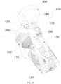
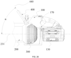
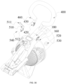
- the handle 400 is movably connected to the housing 100, and the handle 400 is rotatable relative to the housing 100 about a handle axis 410.
- the handle 400 can adaptively rotate about the handle axis 410 so that the posture of the handle 400 relative to the grip 150 is adjusted, thereby ensuring the comfort of the user holding the blower 10 with two hands.
- the handle axis 410 extends along the left and right direction, so the swing of the handle 400 and the adjustment of the posture of the handle 400 in the front and rear direction can be performed.
- FIG. 25 the handle 400 is movably connected to the housing 100, and the handle 400 is rotatable relative to the housing 100 about a handle axis 410.
- the angle of rotation of the handle 400 is ⁇ , and the angle of rotation ⁇ is greater than 10 degrees and less than or equal to 150 degrees, that is, the handle 400 is rotatable within a range of 10 degrees to 150 degrees. It is to be noted that the angle of rotation ⁇ is the maximum angle of rotation from the motor axis 231 of the blower 10 to the rear of the blower 10.
- the handle 400 has at least one lockable position.
- the handle 400 can be locked at a fixed position, thereby better satisfying the operating requirements of the user.
- the handle 400 may be configured to be lockable at one position, two positions, three positions, or any position within a rotatable angle range.
- the blower 10 further includes a mounting assembly 500, and the handle 400 is mounted on the housing 100 through the mounting assembly 500.
- the mounting assembly 500 enables the handle 400 to rotate about the handle axis 410 and enables the handle 400 to be locked at any position within a rotation angle range, thereby satisfying different usage requirements of the user.
- the user rotates the trigger 510 to unlock the handle 400.
- the handle 400 can be rotated so that the angle of the handle 400 can be adjusted.
- the trigger 510 is rotated in reverse so that the trigger 510 locks the handle 400 at the current position.
- the user rotates the trigger 510 to the unlocking position and keeps the trigger 510 at the unlocking position. Therefore, when the blower 10 is in use, the angle of the handle 400 can be automatically adjusted as the air discharge direction of the pipe assembly 260 changes.
- the user rotates the trigger 510 to the unlocking position and removes the fastener 530 from the rotary shaft 520. At this time, the handle 400 and the mounting assembly 500 can be removed from the housing 100, and the user holds the blower 10 only by the grip 150.
- a snap 460 is provided on one of the operating end 511 of the trigger 510 and the mating portion 420 of the handle 400, and a snap groove 5111 is provided on the other one of the operating end 511 of the trigger 510 and the mating portion 420 of the handle 400.
- the snap 460 and the snap groove 5111 can be snap-fitted together so that the positions of the trigger 510 and the handle 400 can be locked, thereby preventing the trigger 510 from being operated incorrectly.
- the snap 460 is provided on the mating portion 420 of the handle 400
- the snap groove 5111 is provided on the operating end 511 of the trigger 510.
- the snap groove 5111 may be provided on the mating portion 420 of the handle 400, and the snap 460 is provided on the operating end 511 of the trigger 510, as long as the snap 460 does not interfere with the rotation of the trigger 510.
- the handle 400 is configured to be an annular structure with a notch, and two ends of the annular structure are mating portions 420 of the handle 400. Two ends of the notch can clamp the left and right sides of the mounting portion 180, respectively.
- the working principle of the trigger 510 in this example is the same as that in the previous example.
- the maximum height of the entire blower 10 is H, where H is greater than or equal to 200 mm and less than or equal to 450 mm.
- H is greater than or equal to 200 mm and less than or equal to 450 mm.
- the maximum height of the blower 10 is set within a range of 200 mm to 450 mm so that the handle 400 has a suitable height. In this manner, it is convenient for the hand of the user to reach into the handle 400, and the dimension of the blower 10 in the height direction is not too large.
- the blower 10 further includes a belt coupling portion 170.
- a belt 800 is usually worn around the waist of the user, and the belt coupling portion 170 is used for mounting the entire blower 10 on the belt 800. Therefore, the belt 800 may be used for supporting the blower 10 with the help of the waist strength of the user, thereby reducing the fatigue of the hands of the user during use.
- the blower 10 here is a handheld blower that cannot be carried on the back of the user for use, rather than a backpack blower with a backpack function.
- the handheld blower has only the grip 150 that implements the main holding function and is located nearby.
- the handheld blower further has the handle 400 that implements the holding function together with the grip 150.
- the handle 400 may be understood as a second handle or an auxiliary handle.
- this example further provides the belt 800 to relieve the pressure on the grip 150.
- the belt 800 helps relieve the pressure on the grip 150 and the handle 400.
- the battery pack 130 of the blower 10 with the belt 800 is usually mounted along a blower axis 101, or the battery pack 130 is usually mounted in the extension region of the wind tube 270.
- the battery pack coupling portion 131 in this example is connected to the housing 100 instead of being provided outside the housing 100.
- the battery pack 130 is mounted on a backpack in the backpack blower.
- the belt coupling portion 170 is located behind the center of gravity G of the blower 10. It is to be noted that the center of gravity G represents the center of gravity of the blower 10 to which the battery pack 130 is mounted. In an example, the belt coupling portion 170 is disposed between an air inlet end of the pipe assembly 260 and the battery pack 130. In an example, the projection of the belt coupling portion 170 on the motor axis 231 is located within the range of the projection of the grip 150 on the motor axis 231. In an example, the belt coupling portion 170 is disposed between the grip 150 and the handle 400. In an example, the belt coupling portion 170 is disposed on the rear side of the center of gravity G.
- the belt coupling portion 170 is set within the preceding range so that the balance state of the blower 10 hung on the belt 800 is consistent with the balance state of the blower 10 held by the hand of the user.
- the blower 10 switches between a handheld state and a waist-hanging state, the user does not need to adjust the habits and skills of using the blower 10, thereby improving the convenience of operating the blower 10 and the user experience.
- the belt 800 includes a belt body 810 and a coupling member 820.
- the belt body 810 is wrapped around and fixed on the waist of the user, and the coupling member 820 is fixed on the belt body 810 and connected to the belt coupling portion 170.
- the belt body 810 includes a looped portion 811 and a shielding portion 812.
- the looped portion 811 is used for surrounding the waist of the user, and two ends of the looped portion 811 may be fixed through a snap connection, a strap connection, or the like.
- a first mounting portion 841 and a second mounting portion 842 are snap-fitted, thereby locking the belt 800.
- the shielding portion 812 is connected to the looped portion 811 and extends downward from the looped portion 811.
- the looped portion 811 has a first height M1 along the up and down direction
- the shielding portion 812 has a second height M2 along the up and down direction, where the second height M2 is greater than or equal to the first height M1.
- the shielding portion 812 has a first length M3 along the left and right direction, and the first length M3 is greater than or equal to the first height M1. In this manner, when the blower 10 is hooked on the belt 800, the shielding portion 812 can separate the blower 10 from the clothes of the user, thereby preventing the blower 10 from sucking the clothes of the user into the air inlet of the blower.
- the coupling member 820 includes a mounting belt 821 and a belt mounting portion 822.
- the coupling member 820 is fixed on the belt body 810.
- the belt mounting portion 822 is connected to the coupling member 820.
- the belt coupling portion 170 can be hooked on the coupling member 820.
- the coupling member 820 may be made of cloth so that the coupling member 820 can be easily connected to the belt body 810.
- the coupling member 820 may be made of metal material to ensure sufficient strength.
- the belt coupling portion 170 and the coupling member 820 are both configured to be hooks.
- one of the belt coupling portion 170 and the coupling member 820 may be configured to be a hook, and the other one of the belt coupling portion 170 and the coupling member 820 may be configured to be a hanging ring.
- the belt coupling portion 170 and the coupling member 820 may be a snap-fit structure, a strap structure, or the like.
- a penetration portion 8211 is provided on the coupling member 820
- the belt 800 further includes two lifting straps 830, the first ends of the two lifting straps 830 are both connected to the belt body 810, and the second ends of the two lifting straps 830 pass through the penetration portion 8211, intersect, and are connected to the belt body 810.
- the two lifting straps 830 are provided to lift the coupling member 820 so that the entire belt 800 can be prevented from being pulled downward excessively due to a larger force on the coupling member 820, thereby improving the user experience.
- the belt coupling portion 170 and the belt mounting portion 822 may each be an open hook, a completely enclosed hook, or a hook that is switchable between the open form and the completely enclosed form.
- the blower 10 further includes an illumination device 600 for increasing the brightness of the surrounding environment when the blower 10 is in operation so that the blower 10 can work well even in a dimly lit environment, thereby improving the user experience.
- the illumination device 600 includes a light assembly 610 and a switch assembly 620.
- the switch assembly 620 is used for controlling the working state of the light assembly 610.
- the light assembly 610 is connected to the housing 100 and disposed on the front side of the handle 400, thereby preventing the handle 400 from blocking the light of the light assembly 610. It is to be noted that the illumination device 600 may include only the light assembly 610 and does not include the switch assembly 620.
- the user may control the light assembly 610 through a device such as a mobile phone that is connected to the blower 10 via signals.
- the illumination device 600 may be provided with a light sensor.
- the light assembly 610 automatically lights up.
- the switch assembly 620 may be integrated with other switch structures of the blower 10.
- the light assembly 610 is disposed toward the front side of the blower 10, and the switch assembly 620 is disposed toward the top of the blower 10, thereby making it easier for the user to see and operate the switch assembly 620.
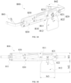
- the switch assembly 620 includes a button 621, a pivot shaft 624, an elastic member 622, and a first circuit board 623.
- the button 621 is pivotally connected to the housing 100 via the pivot shaft 624, and the axis of the pivot shaft 624 is a pivot axis 625.
- the first circuit board 623 is opposite to the button 621, and the first circuit board 623 is electrically connected to the light assembly 610.
- the elastic member 622 is disposed between the button 621 and the housing 100.
- the button 621 rotates about the pivot axis 625 and approaches the first circuit board 623, thereby triggering the electrical components on the first circuit board 623 and lighting the light assembly 610 up.
- the elastic member 622 resets the button 621.
- a mechanical switch is disposed on the first circuit board 623; and when the button 621 is reset, the mechanical switch is turned off, and the light assembly 610 is turned off accordingly.
- an electronic switch is disposed on the first circuit board 623; and when the button 621 is reset, the light assembly 610 is not turned off, and the user needs to press the button 621 again to turn off the light assembly 610.
- the light assembly 610 includes a second circuit board 611 electrically connected to the first circuit board 623.
- Light-emitting elements 614 are disposed on the second circuit board 611.
- the first circuit board 623 is triggered by the button 621, the second circuit board 611 turns on or off the light-emitting elements 614.
- the light-emitting element 614 may be a light-emitting diode (LED) lamp.
- the light assembly 610 further includes a light guide portion 612 and a light-transmissive portion 613.
- the light guide portion 612 is disposed on the front side of the second circuit board 611, and a light guide channel is disposed on the light guide portion 612.
- the light-emitting elements 614 at least partially extend into the light guide channel, thereby limiting the light direction of the light-emitting elements 614.
- the light-transmissive portion 613 covers the front side of the second circuit board 611, thereby protecting the second circuit board 611, the light-emitting elements 614, and the light guide portion 612 and ensuring that the light of the light-emitting elements 614 can propagate.
- the switch assembly 620 and the light assembly 610 are integrated, thereby making the appearance of the blower 10 simpler and more aesthetic.
- the integrated structure of the switch assembly 620 and the light assembly 610 is disposed toward the front side of the blower 10, thereby illuminating the working environment in front of the blower 10.
- the illumination device 600 includes a third circuit board 630 and a button 621 opposite to the third circuit board 630.
- the third circuit board 630 is provided with the light-emitting elements 614 and an electronic switch 640. In some examples, when the user presses the button 621, the button 621 triggers the electronic switch 640, and the third circuit board 630 causes the light-emitting elements 614 to light up.
- the electronic switch 640 is turned off, and the light-emitting elements 614 are turned off accordingly.
- the light-emitting elements 614 have at least two brightnesses.
- the light-emitting elements 614 emit light of the first brightness.
- the light-emitting elements 614 emit light of the second brightness.
- the light-emitting elements 614 are turned off.
- the illumination device 600 further includes a light guide portion 612 and a light-transmissive portion 613.
- the light guide portion 612 is disposed on the front side of the third circuit board 630.
- a light guide channel is formed on the light guide portion 612.
- At least some light-emitting elements 614 are located in the light guide channel.
- the light guide portion 612 guides the light emitted by the light-emitting elements 614.
- the light-transmissive portion 613 is disposed on the front side of the light guide portion 612.
- the light-transmissive portion 613 can protect the third circuit board 630, the light-emitting elements 614, and the light guide portion 612 and ensure that the light of the light-emitting elements 614 can propagate.
- the button 621 is movably connected to the light-transmissive portion 613 so that the light-transmissive portion 613 can support the button 621.
- the blower 10 has the blower axis 101, and the blower axis 101 is collinear with the axis of the pipe assembly 260.
- the included angle between the blower axis 101 and the ground is 25 degrees to 40 degrees.
- S1 is defined as the length of the projection of a line on the ground, where the line is a line between the frontmost end of the blower 10 and the farthest end that the illumination device 600 can illuminate on the ground when the blower 10 is in operation.
- S1 is greater than or equal to 1 m. In some examples, S1 is greater than or equal to 1.5 m. In some examples, S1 is greater than or equal to 2 m. It is to be understood that those skilled in the art may select the light assembly 610 with corresponding performance according to actual requirements for S1.
- S2 denotes the distance between the light assembly 610 and the frontmost end of the blower 10 along the direction of the blower axis 101
- S3 denotes the length of the blower 10 along the direction of the blower axis 101.
- S2/S3 is less than or equal to 0.8. By setting S2/S3 within this ratio range, while the light assembly 610 can be easily mounted, the light assembly 610 can be prevented from being positioned too far back, and the light assembly 610 can be prevented from being blocked by the pipe assembly 260 and creating a large shadow region on the ground, thereby improving the user experience.
- S2/S3 is less than or equal to 0.7. In some examples, S2/S3 is about 0.55 or 0.45.
- the communication board 715 is provided with a Bluetooth module, a Wi-Fi module, or the like.
- the control board 716 is a printed circuit board (PCB), and the control board 716 is electrically connected to the control assembly 720 of the blower 10.
- a light-emitting portion may be a liquid-crystal display (LCD) screen or an LED screen.
- the light-transmissive screen 712 is disposed on the front side of the light-emitting portion. The light-transmissive screen 712 can allow light from the light source 714 to pass through and can protect the light source 714.
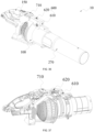
- the mounting portion 90A may be provided on the wind tube 910, the elastic member 920 is mounted in the mounting portion 90A, the first end of the elastic member 920 abuts against the body 11, the second end of the elastic member 920 abuts against the groove bottom of the mounting portion 90A, and when the wind tube 910 is released from the body 11, the elastic member 920 is separated from the body 11 along with the wind tube 910.
- the first groove 932 is formed at an end of the mounting cover 930 facing the wind tube 910, and a protrusion is provided at the end of the wind tube 910 and can extend into a second groove 933, thereby achieving circumferential limitation between the wind tube 910 and the body 11.
- the unlocking member 940 When the wind tube 910 is to be removed, the unlocking member 940 is pushed in a direction facing the wind tube 910 so that the unlocking member 940 abuts against and pushes the wind tube 910, and the wind tube 910 moves away from the body 11.
- the wind tube 910 moves from the first section to the second section until the wind tube 910 is completely separated from the body 11, thereby achieving the removal of the wind tube 910 from the body 11.
- the elastic member 920 is elastically reset to reduce the force for pushing the unlocking member 940, thereby facilitating the operation.
- the body 11 and the wind tube 910 are connected through plugging and loosely mate with each other.
Landscapes
- Engineering & Computer Science (AREA)
- Mechanical Engineering (AREA)
- General Engineering & Computer Science (AREA)
- Physics & Mathematics (AREA)
- Geometry (AREA)
- Life Sciences & Earth Sciences (AREA)
- Environmental Sciences (AREA)
- Architecture (AREA)
- Civil Engineering (AREA)
- Structural Engineering (AREA)
- Structures Of Non-Positive Displacement Pumps (AREA)
Abstract
Description
- The present disclosure claims priority to
Chinese Patent Application No. 202210967982.6 filed with the China National Intellectual Property Administration (CNIPA) on Aug. 12, 2022 Chinese Patent Application No. 202320947789.6 filed with the CNIPA on Apr. 24, 2023 Chinese Patent Application No. 202310456589.5 filed with the CNIPA on Apr. 25, 2023 - The present application relates to an airflow device.
- By rotating fan blades, an airflow device drives gas to flow to do work, thereby implementing the main function of the airflow device. The airflow device may be a blower, a blow-suction machine, or the like. The blower is widely used in gardens, streets, homes, and other environments. The noise of the airflow device is affected by many factors, and the noise may further increase when the flow rate of the blown gas increases. Nowadays, users have higher requirements on the noise generated by the airflow device in operation.
- The blowers usually include a handheld blower and a backpack blower. The backpack blower may be carried on the back of the user for use, so the power and air volume of the backpack blower are usually greater than those of the handheld blower, and the battery capacity of the backpack blower is also usually greater than that of the handheld blower.
- The present application adopts the technical solution below. An airflow device includes a grip for a user to hold; a pipe assembly for the air to pass through; fan blades rotatable about a fan axis; a motor for driving the fan assembly to rotate; and guide vanes for directing the airflow. The guide vane includes multiple through holes penetrating at least part of the guide vane.
- In an example, at least one of the multiple through holes penetrates the guide vane along multiple through hole axes, where the multiple through hole axes are basically parallel to the fan axis of the fan assembly.
- In an example, observing from the front side of the airflow device, at least one of the multiple through holes is basically circular, and the hole diameter D3 of the multiple through holes is greater than or equal to 2 mm and less than or equal to 5 mm.
- In an example, the fan
blade support portion 253 supports thefan blades 252, and the hub ratio is defined as the ratio of the maximum first diameter formed by the fan blade support portion to the second diameter formed by the outermost edges of the fan blades, where the hub ratio is greater than or equal to 0.4 and less than or equal to 0.5. - In an example, along the direction of the fan axis, the first distance L1 is formed between a guide vane root of the guide vane and the fan blade, where the first distance is greater than or equal to 5 mm and less than or equal to 30 mm.
- In an example, a guide vane root of the guide vane intersects with a guide vane support portion, the fan assembly includes a fan front end located on the front side and a fan rear end located on the rear side, the guide vane support portion includes a first rear edge located on the rear side, and the second distance L2 is defined as the distance between the fan front end of the fan assembly and the first rear edge of the guide vane support portion, where the second distance is greater than or equal to 3 mm and less than or equal to 6 mm.
- In an example, the radial thickness L3 of the guide vane is greater than or equal to 9 mm and less than or equal to 15 mm.
- In an example, in the radial direction of a guide vane axis, an opening rate of the guide vane is defined as the ratio of the total opening area of the guide vane to the total radial area of the guide vane, where the opening rate is greater than or equal to 10% and less than or equal to 75%.
- In an example, the ratio T/D of the average wall thickness T of the pipe assembly to the inner diameter D of the pipe assembly is greater than or equal to 1:50 and less than or equal to 1:15.
- In an example, the airflow device is a blower, a blow-suction machine, or another device that performs work through the airflow.
- The present application further adopts the technical solution below. An airflow device includes a grip for a user to hold; a pipe assembly for the air to pass through; a fan assembly including fan blades and a fan blade support portion supporting the fan blades, where the fan blades are rotatable about a fan axis, and the fan assembly is an axial flow fan; a motor for driving the fan assembly to rotate; and guide vanes for directing the airflow. The inner diameter of the pipe assembly is greater than or equal to 90 mm. The flow rate of the airflow device is greater than or equal to 1000 CFM. The maximum rotational speed of the motor is less than 35000 rpm.
- In an example, along the direction of the fan axis, the first distance is formed between a guide vane root of the guide vane and the fan blade, where the first distance is greater than or equal to 5 mm and less than or equal to 30 mm.
- In an example, along the direction of the fan axis, the first distance is formed between a guide vane root of the guide vane and the fan blade, where the first distance is greater than or equal to 5 mm and less than or equal to 20 mm.
- In an example, the pipe assembly includes a first pipe and a second pipe, where the first pipe is located on the front side of the second pipe.
- In an example, the average wall thickness of the pipe assembly is greater than or equal to 3 mm.
- In an example, the hub ratio is defined as the ratio of the maximum first diameter formed by the fan blade support portion to the second diameter formed by the outermost edges of the fan blades, where the hub ratio is greater than or equal to 0.4 and less than or equal to 0.5.
- In an example, a guide vane root of the guide vane intersects with a guide vane support portion, the fan assembly includes a fan front end located on the front side and a fan rear end located on the rear side, the guide vane support portion includes a first rear edge located on the rear side, and the second distance L2 is defined as the distance between the fan front end of the fan assembly and the first rear edge of the guide vane support portion, where the second distance is greater than or equal to 3 mm and less than or equal to 6 mm.
- In an example, the airflow device includes a body, where the body includes the fan assembly, the motor, and a housing, and the housing is formed with the grip; the airflow device further includes a wind tube, the wind tube is detachably connected to the body, and the wind tube allows the air to pass through; the airflow device is provided with an ejection mechanism, and the ejection mechanism applies an ejection force so that the wind tube tends to be separated from the body.
- In an example, the airflow device includes a battery pack coupling portion configured to mount a battery pack for supplying power to the airflow device.
- In an example, the airflow device is a blower, a blow-suction machine, or another device that performs work through the airflow.
- In an example, the airflow device further includes a handle used for the user to hold and located on the front side of the grip.
- In an example, guide vanes for directing the airflow are further included, where the guide vane includes multiple through holes penetrating at least part of the guide vane.
- In an example, the guide vane expands outward from a guide vane axis, and in the radial direction of the guide vane axis, an opening rate of the guide vane is defined as the ratio of the total opening area of the guide vane to the total radial area of the guide vane, where the opening rate is greater than or equal to 10% and less than or equal to 75%.
- In an example, the ratio T/D of the average wall thickness T of the pipe assembly to the inner diameter D of the pipe assembly is greater than or equal to 1:50 and less than or equal to 1:15.
- In an example, the airflow device is capable of being connected to a belt for use, a blower is provided with a belt coupling portion, the belt is provided with a belt mounting portion, and the belt coupling portion and the belt mounting portion are assembled so that the belt is mounted to the blower.
- In an example, the airflow device further includes a display, where the display includes an electronic display screen.
- In an example, the effective area S of the display is defined as the displayable area of the electronic display screen, where the effective area S is greater than or equal to 4 cm2.
- The present application further adopts the technical solution below. An airflow device includes a grip for a user to hold; a pipe assembly for the air to pass through; a fan assembly including fan blades and a fan blade support portion supporting the fan blades, where the fan blades are rotatable about a fan axis of the fan assembly, and the fan assembly is an axial flow fan; and a motor for driving the fan assembly to rotate. The airflow device further includes a handle used for the user to hold and located on the front side of the grip, the flow rate of the airflow device is greater than or equal to 1000 CFM, and the maximum rotational speed of the motor is less than 35000 rpm.
- In an example, guide vanes for directing the airflow are further included, where along the direction of the fan axis, the first distance is formed between a guide vane root of the guide vane and the fan blade, where the first distance is greater than or equal to 5 mm and less than or equal to 20 mm.
- In an example, the inner diameter of the pipe assembly is greater than or equal to 90 mm, and the average wall thickness of the pipe assembly is greater than or equal to 3 mm.
- The present application further adopts the technical solution below. An airflow device includes a grip for a user to hold; a pipe assembly for the air to pass through; a fan assembly including fan blades and a fan blade support portion supporting the fan blades, where the fan blades are rotatable about a fan axis, and the fan assembly is an axial flow fan; a motor for driving the fan assembly to rotate; and guide vanes for directing the airflow. The hub ratio is defined as the ratio of the maximum first diameter D1 formed by the fan blade support portion to the second diameter D2 formed by the outermost edges of the fan blades, where the hub ratio is less than or equal to 0.5.
- In an example, the hub ratio is greater than or equal to 0.4.
- In an example, the maximum rotational speed of the motor is less than 30000 rpm.
- In an example, the maximum rotational speed of the motor is less than or equal to 27500 rpm.
- In an example, the inner diameter of the pipe assembly is greater than or equal to 90 mm.
- In an example, the flow rate of the airflow device is greater than or equal to 1000 CFM.
- In an example, a guide vane includes multiple through holes penetrating at least part of the guide vane.
- In an example, along the direction of the fan axis, the first distance L1 is formed between a guide vane root of a guide vane and the fan blade, where the first distance is greater than or equal to 5 mm and less than or equal to 30 mm.
- In an example, a guide vane root of a guide vane intersects with a guide vane support portion, the fan assembly includes a fan front end located on the front side and a fan rear end located on the rear side, the guide vane support portion includes a first rear edge located on the rear side, and the second distance L2 is defined as the distance between the fan front end of the fan assembly and the first rear edge of the guide vane support portion, where the second distance is greater than or equal to 3 mm and less than or equal to 6 mm.
- In an example, the average wall thickness of the pipe assembly is greater than or equal to 3 mm.
- The present application further adopts the technical solution below. An airflow device includes a grip for a user to hold; a pipe assembly for the air to pass through; fan blades rotatable about a fan axis; a motor for driving the fan assembly to rotate; and guide vanes for directing the airflow. The average wall thickness T of the pipe assembly is greater than 3 mm.
- In an example, the product T*D of the average wall thickness T of the pipe assembly and the inner diameter D of the pipe assembly is greater than or equal to 2700 mm·mm, and the ratio T/D of the average wall thickness T of the pipe assembly to the inner diameter D of the pipe assembly is greater than or equal to 1:50 and less than or equal to 1:15.
- In an example, the flow rate of the airflow device is greater than or equal to 1000 CFM.
- In an example, the inner diameter of the pipe assembly is greater than or equal to 90 mm.
- In an example, the maximum rotational speed of the motor is less than 30000 rpm.
- In an example, the average wall thickness T of the pipe assembly is greater than or equal to 3.5 mm.
- In an example, a conical pipe is formed inside the pipe assembly, the conical pipe extends from a first end located on the front side of the pipe assembly, the conical pipe accommodates at least part of the motor, the distance by which the conical pipe extends from the first end is the fourth distance L4, the guide vane includes a third end facing the fan blade and a fourth end facing away from the fan blade, the distance from the fourth end to the first end is the fifth distance L5, and the ratio L4/L5 of the fourth distance to the fifth distance is greater than or equal to 0 and less than or equal to 0.1.
- In an example, a conical pipe is formed inside the pipe assembly, the conical pipe extends from a first end located on the front side of the pipe assembly, the conical pipe accommodates at least part of the motor, the guide vane includes a third end facing the fan blade and a fourth end facing away from the fan blade, the distance from the fourth end to the first end is the fifth distance L5, and the fifth distance is approximately 0.
- In an example, the airflow device includes a battery pack coupling portion configured to mount a battery pack for supplying power to the airflow device.
- In an example, the airflow device is a blower, a blow-suction machine, or another device that performs work through the airflow.
- The present application further adopts the technical solution below. An airflow device includes a grip for a user to hold; a pipe assembly for the air to pass through; a fan assembly including fan blades and a fan blade support portion supporting the fan blades, where the fan blades are rotatable about a fan axis of the fan assembly; and a motor for driving the fan assembly to rotate. The airflow device further includes a handle used for the user to hold and located on the front side of the grip, and the air volume of the airflow device is greater than 1000 CFM.
- In an example, the handle is rotatable about a handle axis, the angle of rotation of the handle is α, and the angle of rotation α is greater than 10 degrees and less than or equal to 150 degrees.
- In an example, the handle has at least one lockable position.
- In an example, a housing is further included, where the pipe assembly is connected to the housing, and the handle is detachably connected to the housing.
- In an example, a housing and a mounting assembly are further included, where the handle is mounted to the housing through the mounting assembly, and the mounting assembly enables the handle to rotate about a handle axis and enables the handle to be locked at any angle during a rotation process.
- In an example, the mounting assembly includes a trigger, a rotary shaft, and a fastener, the rotary shaft passes through the housing and the handle, the fastener is detachably connected to an end of the rotary shaft, the trigger is hinged to the other end of the rotary shaft, and the trigger is rotatable relative to the rotary shaft so that the trigger has a locking position and an unlocking position, where when the trigger is at the locking position, the handle is clamped between the fastener and the trigger, and when the trigger is at the unlocking position, the handle is rotatable relative to the rotary shaft.
- In an example, an illumination device disposed on the front side of the handle is further included.
- In an example, the inner diameter of the pipe assembly is D, the width of the handle along the left and right direction is W, and W/D is greater than or equal to 1 and less than or equal to 2.5.
- In an example, the handle is rotatable about a handle axis, the angle of rotation of the handle is α, and the angle of rotation is adjusted such that the maximum height of the airflow device supported on a plane is H, where H is greater than or equal to 200 mm and less than or equal to 450 mm.
- In an example, the handle is rotatable about a handle axis, the angle of rotation of the handle is α, and the angle of rotation is adjusted such that the height of the airflow device placed on a plane is H, where the maximum diameter of the pipe assembly is D4, and H/D4 is greater than or equal to 1 and less than or equal to 4.
- The present application further adopts the technical solution below. A handheld blower includes a grip for a user to hold; a pipe assembly for the air to pass through; a fan assembly including fan blades rotatable about a fan axis of the fan assembly; and a motor for driving the fan assembly to rotate. The handheld blower is capable of being connected to a belt for use, the handheld blower is provided with a belt coupling portion, the belt is provided with a belt mounting portion, and the belt coupling portion and the belt mounting portion are assembled so that the belt is mounted to the handheld blower.
- In an example, the belt coupling portion is located behind the center of gravity G of the handheld blower.
- In an example, a battery pack is further included, where the battery pack is used for supplying power to the handheld blower, the battery pack is mounted behind the pipe assembly, and the belt coupling portion is disposed between an air inlet end of the pipe assembly and the battery pack.
- In an example, the belt coupling portion is disposed below the grip.
- In an example, the belt includes a belt body, a coupling member, and a lifting strap, a penetration portion is provided on the coupling member, an end of the lifting strap is connected to the belt body, and the other end of the lifting strap is connected to the belt body after passing through the penetration portion.
- In an example, two lifting straps are provided, an end of one of the two lifting straps and an end of the other one of the two lifting straps are connected to the belt body, and the other end of one of the two lifting straps and the other end of the other one of the two lifting straps pass through the penetration portion, intersect, and are connected to the belt body.
- In an example, a belt body includes a looped portion, the looped portion is used for surrounding the waist of the user, a first mounting portion and a second mounting portion extend from two ends of the looped portion, and the first mounting portion and the second mounting portion are assembled so that the belt is capable of being locked to the waist of the user.
- In an example, the belt body further includes a shielding portion connected to the looped portion and extending downward from the looped portion.
- In an example, the looped portion has a first height M1 along the up and down direction, and the shielding portion has a second height M2 along the up and down direction, where the second height M2 is greater than or equal to the first height M1.
- In an example, the looped portion has a first height M1 along the up and down direction, and the shielding portion has a first length M3 along the left and right direction, where the first length M3 is greater than or equal to the first height M1.
- The present application further adopts the technical solution below. A handheld blower includes a grip for a user to hold; a pipe assembly for the air to pass through; a fan assembly including fan blades rotatable about an axis of the fan assembly; and a motor for driving the fan assembly to rotate. The handheld blower further includes a display, where the display includes an electronic display screen.
- In an example, the display is disposed on the front side of the grip.
- In an example, a handle for the user to hold is further included, where the display is disposed between the grip and the handle.
- In an example, a housing is further included, where the pipe assembly is disposed on the front side of the housing, and the display is disposed on the housing.
- In an example, a control assembly is further included, where the minimum distance between the display and the control assembly is less than or equal to 100 mm.
- In an example, a battery pack for supplying power to the handheld blower is further included, where the display is capable of displaying at least one of the power capacity of the battery pack, the output rotational speed of the handheld blower, an operation gear of the handheld blower, a fault prompt, and a Bluetooth connection state.
- In an example, an illumination device is further included.
- In an example, a handle for the user to hold is further included, where the illumination device is disposed on the front side of the handle.
- In an example, the display includes screen box soft rubber, a light-transmissive screen, screen box hard rubber, a light source, a communication board, and a control board.
- In an example, the effective area S of the display is defined as the displayable area of the electronic display screen, where the effective area S is greater than or equal to 4 cm2.
-
-
FIG. 1 is a perspective view of a blower from one perspective. -
FIG. 2 is an exploded view of a blower. -
FIG. 3 is an exploded view of a pipe assembly shown inFIG. 2 . -
FIG. 4 is a sectional view of some structures of the blower shown inFIG. 1 . -
FIG. 5 is a partial enlarged view of a region inFIG. 4 . -
FIG. 6 is a perspective view of a fan assembly. -
FIG. 7 is a side view of the fan assembly inFIG. 6 . -
FIG. 8 is a front view of the fan assembly inFIG. 6 . -
FIG. 9 is a perspective view of a second pipe inFIG. 3 . -
FIG. 10 is a front view of the second pipe inFIG. 9 . -
FIG. 11 is a partial enlarged view of a region inFIG. 10 . -
FIG. 12 is a perspective view of the second pipe inFIG. 9 from another perspective. -
FIG. 13 is a sectional perspective view of the second pipe inFIG. 12 . -
FIG. 14 is a perspective view of a first pipe inFIG. 3 . -
FIG. 15 is a perspective view of a pipe assembly in another example. -
FIG. 16 is a side view of the pipe assembly inFIG. 15 . -
FIG. 17 is a sectional perspective view of the pipe assembly inFIG. 15 . -
FIG. 18 is a side view of a pipe assembly in another example. -
FIG. 19 is a schematic view of an attempt. -
FIG. 20 is a schematic view of another attempt. -
FIG. 21 is a graph illustrating the modal frequency relationship for different average wall thicknesses. -
FIG. 22 is a schematic view of a blower from another perspective. -
FIG. 23 is an exploded view of a blower. -
FIG. 24 is an exploded view of a pipe assembly. -
FIG. 25 is a partial structural view of a blower. -
FIG. 26 is a side view of structures inFIG. 25 . -
FIG. 27 is an exploded view of a mounting assembly and a first handle of a blower. -
FIG. 28 is a sectional view of the blower provided inFIG. 27 when a trigger is in a locked state. -
FIG. 29 is a sectional view of the blower provided inFIG. 27 when a trigger is in an unlocked state. -
FIG. 30 is an exploded view of a mounting assembly and a second handle of a blower. -
FIG. 31 is a front view of a blower provided with a first handle. -
FIG. 32 is a front view of a blower provided with a second handle. -
FIG. 33 is a side view of a blower. -
FIG. 34 is a perspective view of a belt. -
FIG. 35 is an expansion view of a belt. -
FIG. 36 is a structural view of a handheld blower. -
FIG. 37 is a partial structural view of a handheld blower. -
FIG. 38 is a partial enlarged view of a region inFIG. 37 . -
FIG. 39 is an exploded view of a light assembly. -
FIG. 40 is a structural view of another handheld blower. -
FIG. 41 is an exploded view of an illumination device. -
FIG. 42 is a side view of a handheld blower. -
FIG. 43 is a structural view of a display. -
FIG. 44 is an exploded view of a display. -
FIG. 45 is an exploded view of a body and a wind tube according to an example. -
FIG. 46 is an exploded view of a blow-suction structure provided inFIG. 45 . -
FIG. 47 is an exploded view of an outer housing, the blow-suction structure, and a wind tube provided inFIG. 46 . -
FIG. 48 is a schematic view of a blower provided inFIG. 46 without a second housing. -
FIG. 49 is an enlarged view of part A inFIG. 48 . -
FIG. 50 is an exploded view of a mounting cover and an elastic member from one perspective. -
FIG. 51 is an exploded view of a mounting cover and an elastic member from another perspective. -
FIG. 52 is a partial sectional view of a blower in a state in which a wind tube is disassembled. -
FIG. 53 is a partial sectional view of a blower in a state in which a wind tube is not disassembled. -
FIG. 54 is a partial schematic view of a blower in a state in which a wind tube is not disassembled. -
FIG. 55 is another schematic view illustrating the installation of an elastic member of a blower in a state in which a wind tube is not disassembled. -
FIG. 56 is another schematic view of a wind tube. -
FIG. 57 is a sectional view of a blower. -
FIG. 58 is an enlarged view of part B inFIG. 57 . - In this application, the terms "comprising", "including", "having" or any other variation thereof are intended to cover an inclusive inclusion such that a process, method, article or device comprising a series of elements includes not only those series of elements, but also other elements not expressly listed, or elements inherent in the process, method, article, or device. Without further limitations, an element defined by the phrase "comprising a ..." does not preclude the presence of additional identical elements in the process, method, article, or device comprising that element.
- In this application, the term "and/or" is a kind of association relationship describing the relationship between associated objects, which means that there can be three kinds of relationships. For example, A and/or B can indicate that A exists alone, A and B exist simultaneously, and B exists alone. In addition, the character "/" in this application generally indicates that the contextual associated objects belong to an "and/or" relationship.
- In this application, the terms "connection", "combination", "coupling" and "installation" may be direct connection, combination, coupling or installation, and may also be indirect connection, combination, coupling or installation. Among them, for example, direct connection means that two members or assemblies are connected together without intermediaries, and indirect connection means that two members or assemblies are respectively connected with at least one intermediate members and the two members or assemblies are connected by the at least one intermediate members. In addition, "connection" and "coupling" are not limited to physical or mechanical connections or couplings, and may include electrical connections or couplings.
- In this application, a person of ordinary skill in the art will understand that relative terms (e.g., "about", "approximately", "substantially", etc.) used in conjunction with quantities or conditions include the values and have the meaning indicated by the context. For example, the relative term includes at least the degree of error associated with the measurement of a specific value, the tolerance caused by manufacturing, assembly, use, etc. associated with a specific value. Such terms should also be regarded as disclosing a range defined by the absolute values of the two endpoints. Relative terms may refer to the addition or subtraction of a certain percentage (e.g., 1%, 5%, 10% or more) of the indicated value. Numerical values that do not use relative terms should also be disclosed as specific values with tolerances. In addition, "substantially" when expressing a relative angular position relationship (e.g., substantially parallel, substantially perpendicular) may refer to adding or subtracting a certain degree (e.g., 1 degree, 5 degrees, 10 degrees or more) on the basis of the indicated angle. In the present application, a person of ordinary skill in the art will understand that the function performed by a component may be performed by one component, multiple components, one part, or multiple parts. Similarly, the function performed by a part may also be performed by one part, one component, or a combination of multiple parts.
- In this application, the terms "upper", "lower", "left", "right", "front", "back" and other directional words are described in terms of the orientation and position relationship shown in the accompanying drawings. In addition, in the context, it is also necessary to understand that when it is mentioned that an element is connected to another element "upper" or "lower", it can not only be directly connected to another element "upper" or "lower", but also indirectly connected to another element "upper" or "lower" through an intermediate element. It should also be understood that the directional words such as upper side, lower side, left side, right side, front side, back side, etc. not only represent the positive orientation, but can also be understood as the side orientation. For example, the bottom may include directly below, lower left, lower right, lower front, and lower back, etc.
- The present application is applicable to an airflow device, which can implement functions including one or two of blowing and suction. That is to say, the airflow device may be a fan. For example, the airflow device may be a blower, a blow-suction machine, or another device that needs to blow or suck the airflow to do work. The blower accelerates the air through the rotation of the fan and pushes an object to be moved through the airflow. The blow-suction machine has two functions: blowing and suction so that the blow-suction machine can push the object through the airflow and suck the object through the airflow. The blower and the blow-suction machine are often used in fields such as garden cleaning.
- The technical solution of the present application is described below using a
blower 10 as an example. - As shown in
FIGS. 1 to 4 , theblower 10 includes ahousing 100, a blow-suction structure 200, and a power supply system. Thehousing 100 forms an accommodation space that can accommodate at least part of the blow-suction structure 200, and thehousing 100 is formed with or connected to agrip 150 for the user to hold. The blow-suction structure 200 includes functional assemblies for implementing blowing and suction functions, such as amotor 230, afan assembly 250, and guidevanes 282. The blow-suction structure 200 further includes apipe assembly 260 for fixing and accommodating the preceding functional assemblies and providing a channel for the airflow. Avent cover 300 is used for sucking air into the blow-suction structure 200. In this example, thevent cover 300 is grid-shaped. Thehousing 100 connects and fixes thevent cover 300 to the blow-suction structure 200. Air is sucked into theblower 10 through thevent cover 300 and driven by thefan assembly 250 in the blow-suction structure 200 to be blown out from afirst end 201 of the blow-suction structure 200. - In this example, the
housing 100 includes aleft housing 110 and aright housing 120, and theleft housing 110 and theright housing 120 together form thegrip 150 for the user to hold. Theleft housing 110 forms afirst coupling portion 111, theright housing 120 forms asecond coupling portion 121, and thefirst coupling portion 111 and thesecond coupling portion 121 together form a batterypack coupling portion 131 for mounting abattery pack 130. Thebattery pack 130 may supply power to theblower 10, and theblower 10 may use mains power. The lower end of theleft housing 110 is formed with or connected to afirst bracket 112, and the lower end of theright housing 120 is formed with or connected to asecond bracket 122. When theblower 10 is placed on a plane, thefirst bracket 112 and thesecond bracket 122 support the blow-suction structure 200 so that theblower 10 does not fall over. In an example, thegrip 150 may be provided independently of thehousing 100, that is to say, thegrip 150 may not be formed by extending from thehousing 100. - As shown in
FIGS. 2 to 4 , thepipe assembly 260 is connected to thehousing 100, and at least part of thepipe assembly 260 is wrapped and/or fixed by thehousing 100. Thepipe assembly 260 is used for the air to pass through and includes afirst end 201 and asecond end 202. At least part of the airflow flows between thefirst end 201 and thesecond end 202. For theblower 10 in this example, the rotation of themotor 230 drivesfan blades 252 to rotate so that the air outside theblower 10 enters thesecond end 202 of thepipe assembly 260 from thevent cover 300, flows through thefan blades 252, theguide vanes 282, and aconical pipe 223 in sequence, and finally flows out from thefirst end 201 of thepipe assembly 260. For the blow-suction machine, when the blow-suction machine is in a suction mode, the airflow flows in a direction opposite to that in the preceding blower. - As shown in
FIGS. 6 and 7 , thefan assembly 250 includesfan blades 252 and a fanblade support portion 253, and thefan blades 252 are mounted on the fanblade support portion 253 or integrally formed with the fanblade support portion 253. Thefan blades 252 are rotatable about afan axis 251. Thefan assembly 250 may be an axial flow fan or a centrifugal fan. - As shown in
FIGS. 3 and4 , themotor 230 includes amotor output shaft 232, themotor output shaft 232 extends along amotor axis 231, and thefan axis 251 of thefan blades 252 basically coincides with themotor axis 231. A rear end 254 (referring toFIG. 7 ) of thefan assembly 250 has a hollow structure inside. Themotor output shaft 232 extends into the fanblade support portion 253 of thefan assembly 250. Themotor output shaft 232 and thefan assembly 250 are fixed by screws. -
FIG. 4 andFIGS. 9 to 14 disclose the structures of asecond pipe 240 and theguide vanes 282 therein. - As shown in
FIG. 4 , in this example, thepipe assembly 260 includes afirst pipe 220 and asecond pipe 240. The guide vanes 282 includefirst guide vanes 242 and second guide vanes 222. Thefirst guide vanes 242 are located in thesecond pipe 240, and thesecond guide vanes 222 are located in thefirst pipe 220. Theblower 10 further includes a guidevane support portion 281 for supporting the guide vanes 282. The guidevane support portion 281 includes a first guidevane support portion 241 and a second guidevane support portion 221. The first guidevane support portion 241 supports thefirst guide vanes 242, and the second guidevane support portion 221 supports the second guide vanes 222. Aguide vane root 2431 of thefirst guide vane 242 is located on the first guidevane support portion 241, and thefirst guide vane 242 connects the first guidevane support portion 241 to an outer housing of thesecond pipe 240. As shown inFIG. 12 , threefirst guide vanes 242 are disposed on the first guidevane support portion 241. The first guidevane support portion 241 forms an accommodation space for accommodating at least part of themotor 230. The screw passes through a mountinghole 246 to fix themotor 230 into thesecond pipe 240. Aguide vane axis 249 passes through the center of thefirst guide vane 242. Thefirst guide vanes 242 are arranged at intervals in the circumferential direction of theguide vane axis 249. Thefirst guide vanes 242 and the first guidevane support portion 241 extend basically along the radial direction of theguide vane axis 249. - It is to be noted that, as shown in
FIG. 3 , in this example, thepipe assembly 260 further includes aprotective cover 210, and theprotective cover 210 is not theguide vane 282. Theprotective cover 210 is disposed at the frontmost side of theconical pipe 223 and may be used for reminding the operator not to put hands into theblower 10. In this example, four ribs are provided on theprotective cover 210, and threeguide vanes 282 are provided. In addition, as shown inFIG. 4 , theguide vanes 282 are disposed between thefan blades 252 and theprotective cover 210, and theguide vanes 282 are disposed between thefan blades 252 and theconical pipe 223. The second guidevane support portion 221 extends forward and is connected to theconical pipe 223. Therefore, in other words, theguide vanes 282 surround and support theconical pipe 223. After the airflow flows in through thevent cover 300 of thesecond end 202 of theblower 10 and is accelerated by thefan blades 252, the airflow is guided by theguide vanes 282 to flow along the outer wall of theconical pipe 223 to anair port 2231 on the front side of theconical pipe 223. At this time, a part of the airflow passes through theprotective cover 210 and flows out from thesecond end 201 of theblower 10, and the other part of the airflow flows back from theair port 2231 to themotor 230 to help the motor dissipate heat. - As shown in
FIGS. 10 and 11 , thefirst guide vane 242 includes multiple throughholes 243 penetrating at least part of thefirst guide vane 242. In this example, eachfirst guide vane 242 is provided with multiple throughholes 243. In this example, the radial thickness L3 of thefirst guide vane 242 is greater than or equal to 9 mm and less than or equal to 15 mm. In an example, the radial thickness L3 is about 11 mm. In an example, the radial thickness L3 is about 13 mm. When the fluid flows through thefirst guide vane 242, part of the fluid passes through the multiple through holes in theguide vane 242 so that flow diversion, vibration damping, and noise reduction can be achieved. - As shown in
FIG. 11 , when thefirst guide vane 242 is observed from the front side of the airflow device or theblower 10, at least one of the multiple throughholes 242 is basically circular, and the hole diameter D3 of each of the multiple throughholes 242 is greater than or equal to 2 mm and less than or equal to 5 mm. In an example, the hole diameter D3 is about 2.5 mm. In an example, the hole diameter D3 is about 3 mm. In an example, the hole diameter D3 is about 3.5 mm. In an example, the hole diameter D3 is about 4 mm. It is to be noted that the shapes of the multiple throughholes 243 are not limited as long as the fluid such as air can pass through the inside of the multiple throughholes 243. It is to be noted that, in this example, basically circular includes both a circle in the geometric sense and an ellipse with a ratio of the major axis length to the minor axis length being between 0.9 and 1.1. - As shown in
FIG. 5 , in this example, at least one of the multiple throughholes 243 penetrates thefirst guide vane 242 along a throughhole axis 2432, and the throughhole axis 2432 is basically parallel to thefan axis 251 of thefan assembly 250. Since thefan axis 251 is basically parallel to theguide vane axis 249, the throughhole axis 2432 is also basically parallel to theguide vane axis 249. The "punching direction" of the multiple throughholes 243 is basically consistent with the motion direction of the fluid such as air. The multiple throughholes 243 penetrate thefirst guide vane 242 along throughhole axes 2432, and the throughhole axes 2432 are basically parallel to thefan axis 251 of thefan assembly 250. In this example, the throughhole axes 2432 are also basically parallel to theguide vane axis 249 and thefan axis 251. In an example, the throughhole axes 2432 of the multiple throughholes 243 may form an included angle with theguide vane axis 249, and the included angle is greater than 0 degrees and less than or equal to 50 degrees. Within this angle range, the multiple throughholes 243 guide the flow direction of the fluid to a certain extent, thereby reducing the vibration and noise generated when the fluid "collides" with the first guide vanes 242. In some examples, the included angle may be 10 degrees, 20 degrees, or 30 degrees. It is to be noted that, in this example, basically parallel includes both absolute parallelism of two axes in the geometric sense and a state in which the included angle between the two axes is relatively small, such as a state in which the included angle between the two axes is within 10 degrees. - For ease of description, as shown in
FIGS. 9 ,12 , and13 , thefirst guide vane 242 includes at least afirst surface 2421 and asecond surface 2422. In this example, thefirst surface 2421 is an outwardly convex surface, and thesecond surface 2422 is an inwardly concave surface. When the fluid flows to thefirst surface 2421, a part of the fluid passes through the multiple throughholes 242, and the other part of the fluid continues flowing along the first surface of thefirst guide vane 242. Finally, a part of all the fluid passing through thefirst guide vane 242 flows out from the first end 201 (referring toFIG. 2 ) of thepipe assembly 260, and the other part enters theair port 2231 of theconical pipe 223 and flows back to themotor 230 to help themotor 230 to dissipate heat. - As shown in
FIG. 11 , in the radial direction of theguide vane axis 249, the opening rate of thefirst guide vane 242 is defined as the ratio of the total opening area of thefirst guide vane 242 to the total area of thefirst guide vane 242, and the opening rate is greater than or equal to 10% and less than or equal to 75%. In an example, the opening rate is greater than or equal to 20% and less than or equal to 50%. In an example, the opening rate may be 25%, 30%, or 40%. Limiting the range of the opening rate is equivalent to limiting the proportion of the fluid that can flow through the inside of thefirst guide vane 242 so that while the guiding capability of thefirst guide vane 242 is not greatly reduced, the degree of the impact between the fluid and thefirst surface 2421 of thefirst guide vane 242 can be reduced, thereby reducing the vibration and noise. - It is to be noted that the space formed between two
adjacent guide vanes 282 is not the multiple throughholes 243 mentioned in the present application, and the multiple throughholes 243 are formed on thesame guide vane 282. The opening rate is also for thesame guide vane 282. In an example,different guide vanes 282 on thesame blower 10 may have different opening rates, anddifferent guide vanes 282 on thesame blower 10 may have different through-hole shapes. - Referring to
FIGS. 4 and 5, FIG. 5 is a partial enlarged view ofFIG. 4 . As shown inFIG. 5 , along the direction of thefan axis 251, the first distance L1 is formed between theguide vane root 2431 of thefirst guide vane 242 and thefan blade 252, where the first distance L1 is greater than or equal to 5 mm and less than or equal to 30 mm. It is to be noted that theguide vane root 2431 refers to the rearmost side of the intersection of thefirst guide vane 242 and the first guidevane support portion 241. As shown inFIG. 5 , a projection of theguide vane root 2431 on thefan blade 252 along the direction of theguide vane axis 249 is afirst point 2521 on thefan blade 252, and the distance between theguide vane root 2431 and thefirst point 2521 is the first distance L1. - In an example, the first distance L1 is greater than or equal to 5 mm and less than or equal to 30 mm. In an example, the first distance L1 is greater than or equal to 5 mm and less than or equal to 20 mm. In an example, the first distance L1 is greater than or equal to 20 mm and less than or equal to 30 mm. In some examples, the first distance L1 is about 100 mm, 15 mm, or 20 mm. According to the preceding settings, when the first distance L1 is greater than or equal to 5 mm and less than or equal to 30 mm, the distance set between the
first guide vane 242 and thefan blade 252 can make the fluid flow from thefan blade 252 to thefirst guide vane 242 at a more appropriate speed and impact force, and the vibration and noise generated when the fluid "collides" with thefirst guide vane 242 are not too large. If the first distance L1 is greater than 30 mm, the distance between thefan blade 252 and thefirst guide vane 242 is too large, affecting the flow guiding effect of thefirst guide vane 242. If the first distance L1 is less than 5 mm, the distance between thefan blade 252 and thefirst guide vane 242 is too small, and the vibration and noise generated by the airflow are relatively large. - The
fan assembly 250 includes a fanfront end 255 located on the front side and a fanrear end 254 located on the rear side, and the first guidevane support portion 241 includes a firstrear edge 248 located on the rear side (referring toFIG. 9 ). The second distance L2 is defined as the distance between the fanfront end 255 of thefan assembly 250 and the firstrear edge 248 of the first guidevane support portion 241, and the second distance L2 is greater than or equal to 3 mm and less than or equal to 6 mm. At the second distance L2, the heat dissipation performance of themotor 230 is better. - As shown in
FIG. 4 , the average wall thickness T of thepipe assembly 260 is greater than or equal to 3 mm. It is to be noted here that the average wall thickness T refers to the average thickness of the pipe wall of thepipe assembly 260. For example, the average wall thickness T of thefirst pipe 220 is greater than or equal to 3 mm, and the average wall thickness T of thesecond pipe 240 is greater than or equal to 3 mm. The average wall thickness here does not take into account the local wall thickness increase caused by the irregular thickness increase on the outer side of thepipe assembly 260. For example, the thickness increase caused by afirst protrusion 262 on thefirst pipe 220 is not taken into account in the average wall thickness of thefirst pipe 220 and the average wall thickness of thepipe assembly 260. For another example, the local thickness increase caused by a firstconvex ring 261 on thesecond pipe 240 is not taken into account in the average wall thickness of thesecond pipe 240 and the average wall thickness of thepipe assembly 260. In this example, thefirst protrusion 262 and the firstconvex ring 261 may be provided to implement functions such as assembly or local reinforcement. Regardless of whether thefan assembly 250 is a centrifugal fan or an axial flow fan, the vibration of the fan and the noise generated by the vibration can be reduced as long as the average wall thickness T of thepipe assembly 260 is greater than or equal to 3 mm. - In an example, the inner diameter D of the
first pipe 220 is greater than or equal to 90 mm. In some examples, the inner diameter D may be 95 mm, 100 mm, 105 mm, 1100 mm, 115 mm, or 125 mm. The product T*D of the average wall thickness T of the pipe assembly and the inner diameter D of the pipe assembly is greater than or equal to 2700 mm·mm, and the ratio T/D of the average wall thickness T of the pipe assembly to the inner diameter D of the pipe assembly is greater than or equal to 1:50 and less than or equal to 1:15. - According to the blower design in the related art, the average wall thickness of the
pipe assembly 260 is mostly less than 3 mm, thereby achieving a smaller overall weight. On the other hand, when the average wall thickness of thepipe assembly 260 is less than 3 mm, if the inner diameter D of thepipe assembly 260 increases to be greater than or equal to 90 mm, theoretically, the stiffness of thepipe assembly 260 increases. - When the average wall thickness T of the
pipe assembly 260 is constant, the larger the inner diameter of thepipe assembly 260 is, the larger the tensile and compressive stiffness, shear stiffness, and bending stiffness of thepipe assembly 260 are. Therefore, when the average wall thickness T of the blower increases, the stiffness increases. Initially, the applicant performs exploration by simply increasing the stiffness of thepipe assembly 260. As shown inFIG. 19 , the applicant attempts to change the housing of thepipe assembly 260 from a gentle arc shape to a polygonal shape to try to increase the stiffness to reduce the vibration. As shown inFIG. 20 , the applicant attempts to add a series of mesh ribs to the outer wall of thepipe assembly 260 to increase the stiffness of the material to reduce the vibration. However, both approaches to increasing the material stiffness inFIGS. 19 and 20 fail to achieve the effect of reducing the vibration of thepipe assembly 260. - Through deductions, simulations, and experiments, it is finally concluded that we need to increase the wall thickness of the
pipe assembly 260 to reduce the tiny amplitude generated by thepipe assembly 260, thereby reducing the noise. - A concept needs to be introduced here: modal frequency. The pipe is used as an example. When the wall thickness is constant, the larger the outer diameter of the pipe is, the lower the modal frequency is, and the more modes exist within a test range. When the outer diameter of the pipe is constant, the larger the wall thickness is, the higher the modal frequency is, and the few modes exist within a test range. The magnitude of the number of modes reflects the magnitude of the noise generated by the vibration. By increasing the modal frequency and reducing the number of modes within a certain test range, the applicant reduces the noise generated by the structural vibration of the blower.
- As shown in
FIG. 21 , the simulation results show that for thepipe assembly 260 with an inner diameter D of 90 mm, when the average wall thickness T of thepipe assembly 260 increases from 2 mm to 3 mm, the modal order of the same frequency shifts to the left, that is, the number of modes decreases, and the vibration is damped, thereby reducing the noise. - In an example, the average wall thickness T of the
pipe assembly 260 is greater than or equal to 3 mm and less than or equal to 5 mm. In an example, the average wall thickness T of thepipe assembly 260 is greater than or equal to 3.5 mm. In some examples, the average wall thickness T of thepipe assembly 260 is about 3.5 mm, 4 mm, or 4.5 mm. When the average wall thickness of thepipe assembly 260 is too small, the housing of thepipe assembly 160 may vibrate too much, thereby causing excessive noise. When the average wall thickness of thepipe assembly 260 is too large, theblower 10 may be too heavy, affecting the operating experience of the user. - As shown in
FIG. 8 , the hub ratio is defined as the ratio of the maximum first diameter D1 formed by the fanblade support portion 253 to the second diameter D2 formed by the outermost edges of thefan blades 252. The hub ratio may also be defined as the ratio of the diameter formed by the tops of thefan blades 252 to the diameter formed by the roots of thefan blades 252 when thefan blades 252 rotate. The hub ratio is greater than or equal to 0.4 and less than or equal to 0.5. In an example, the first diameter D1 is about 47.2 mm and the hub ratio is about 0.46. In an example, the flow rate of theblower 10 is greater than or equal to 1000 CFM, the fan assembly is an axial flow fan, and the hub ratio is greater than or equal to 0.4 and less than or equal to 0.5. - Table one shows the flow rates, wind speeds, kinetic energy efficiencies, thrusts, and other parameters outputted by the
blowers 10 with different hub ratios when the inner diameter D of thepipe assembly 260 is 105 mm and themotor 230 has different rotational speeds. The flow rate mentioned in the present application refers to the mass flow rate, and the wind speed refers to the wind speed at the outlet of the blower. The kinetic energy efficiency refers to (0.5*wind speed squared*mass flow rate)/fan loss.Table one Hub ratio Rotational speed (rpm) Mass flow rate (kg/s) Volume flow rate (m3/s) Volume flow rate (CFM) Wind speed (m/s) Loss (W) Kinetic energy efficiency Thrust (N) 0.45 25000 0.66 0.55 1173 70.9 2446 0.67 46.50 0.55 25000 0.61 0.52 1091 65.9 2461 0.54 40.22 0.45 32000 0.84 0.71 1502 90.7 5131 0.67 76.20 0.55 32000 0.78 0.66 1396 84.4 5161 0.54 65.89 0.45 35000 0.92 0.78 1643 99.3 6713 0.67 91.16 0.55 35000 0.85 0.72 1527 92.3 6753 0.54 78.82 - It can be seen from the preceding table that when the rotational speed of the motor is constant, the volume flow rate, wind speed, and thrust of the blower with a hub ratio of 0.45 are all greater than those of the blower with a hub ratio of 0.55, and the blower with a hub ratio of 0.45 has a higher kinetic energy efficiency, which means that a higher proportion of inputted energy can be converted into airflow kinetic energy. When the hub ratio is constant, the larger the rotational speed of the motor is, the larger the volume flow rate, wind speed, kinetic energy efficiency, and thrust of the blower are. By reducing the hub ratio to less than 0.5 and applying other technologies, the maximum rotational speed of the motor does not need to increase to 35000 rpm to achieve an air volume greater than or equal to 1000 CFM. The rotational speed of the motor is relatively small so that the life of the bearings for positioning the motor can be extended, and the motor has a lower heat dissipation requirement, which is conducive to extending the life of the
blower 10. When the hub ratio is greater than 0.5, the efficiency of the whole machine is relatively high. Therefore, if the hub ratio is to be reduced to a range of 0.4 to 0.5, other technical solutions in this specification are needed to improve the efficiency of the whole machine. When the maximum rotational speed of the motor is greater than or equal to 35000 rpm, the dynamic balance of the whole machine is affected, causing greater vibration of the whole machine and affecting the service life. - It is to be noted that the inner diameter D of the
first pipe 220 of theblower 10 is not limited. That is to say, theblowers 10 with various inner diameters may all adopt the method of providing the throughholes 243 on thefirst guide vane 242 to reduce the vibration and noise. In an example, the inner diameter D of thefirst pipe 220 is greater than or equal to 90 mm. In some examples, the inner diameter D may be 95 mm, 100 mm, 105 mm, 1100 mm, 115 mm, or 125 mm. - Generally speaking, the
blower 10 with a larger inner diameter D has a larger flow rate and makes greater noises. Therefore, applying the solution disclosed in the present application to theblower 10 with an inner diameter D greater than or equal to 90 mm can achieve more obvious vibration damping and noise reduction effects, but it does not mean that the technical solution of the present application is suitable for only the application to theblower 10 with an inner diameter D greater than or equal to 90 mm. - As shown in
FIG. 14 , thefirst pipe 220 includes the second guide vanes 222. When thefirst pipe 220 and thesecond pipe 240 are coupled together, thesecond guide vane 222 is engaged with thefirst guide vane 242. Thesecond guide vanes 222 are disposed on the outer side of theconical pipe 223 to keep theconical pipe 223 stable. - As shown in
FIGS. 15 to 18 , in an example, aconical pipe 223a is formed inside apipe assembly 260a, and theconical pipe 223a extends from afirst end 2011a located on the front side of thepipe assembly 260a. Theconical pipe 223a accommodates at least part of themotor 230, and the distance by which theconical pipe 223a extends from thefirst end 2011a is the fourth distance L4. Theguide vane 282 includes a third end facing thefan blade 252 and afourth end 2223 facing away from the fan blade. The distance from thefourth end 2223 to the first end is the fifth distance L5. The ratio L5/L4 of the fifth distance to the fourth distance is greater than or equal to 0 and less than or equal to 0.1. - In the example disclosed in
FIGS. 15 to 17 , the fifth distance is about 0, that is to say, thefourth end 2223 of theguide vane 282 is basically flush with thefirst end 2011a of thepipe assembly 260a. In the example disclosed inFIG. 18 , the fifth distance is not 0, and the ratio L5/L4 of the fifth distance to the fourth distance is less than or equal to 0.1. In this manner, the end of theguide vane 282 is basically flush with thefirst end 2011a of thepipe assembly 260a, and the vibration of the housing of thepipe assembly 260 can be damped by theguide vane 282. - As shown in
FIG. 18 , apipe assembly 260b has afirst end 2011b, and thefirst end 2011b of thepipe assembly 260b should try not to exceed the end of theguide vane 282. Even if thefirst end 2011b of thepipe assembly 260b exceeds the end of theguide vane 282, if L5/L4 is greater than or equal to 0 and less than or equal to 0.1, the vibration of the housing of thepipe assembly 260a can be controlled within a reasonable range to prevent generating huge noise. - When the flow rate of the
blower 10 is greater than or equal to 1000 CFM, the inner diameter D of thepipe assembly 260 is generally greater than or equal to 90 mm to satisfy the requirement for outputting a large flow rate. In an example, the inner diameter D of thepipe assembly 260 is greater than or equal to 90 mm, the air volume of theblower 10 is greater than or equal to 1000 CFM, the operating rotational speed of themotor 230 is lower than 35000 rpm, and thefan assembly 250 is an axial flow fan. In the present application, the blow-suction structure 200 is optimized so that when the inner diameter D of the blowingassembly 260 is greater than or equal to 90 mm and the operating rotational speed of themotor 230 is not higher than 35000 rpm, the flow rate of theblower 10 can still be greater than or equal to 1000 CFM. That is to say, by limiting thefirst guide vanes 242, the multiple throughholes 243, the average wall thickness D of thepipe assembly 260, the hub ratio of thefan assembly 250, and the first distance between theguide vane root 2431 of thefirst guide vane 242 and thefan blade 252, when the rotational speed of themotor 230 does not increase to 35000 rpm, the air volume of the blower can be greater than 1000 CFM, and the air discharge effect of the whole machine is better. - In an example, the maximum rotational speed of the motor is less than or equal to 30000 rpm, and the flow rate of the airflow device is greater than or equal to 1000 CFM. In an example, the maximum rotational speed of the motor is less than or equal to 27500 rpm, and the flow rate of the airflow device is greater than or equal to 1000 CFM.
- The technical solution involved in the present application can be applied to both the blower and the blow-suction machine and can achieve the effect of optimizing vibration and noise. Therefore, the technical solution of the present application is also applicable to the blow-suction machine. In addition, the airflow device involved in the present application may also be a device with blowing and/or suction capabilities that is different from the blower and the blow-suction machine in the related art, such as a device that implements the main function of the airflow device by doing useful work through the airflow.
- For the blow-suction machine that can blow and suck air, the technical solution involved in the present application may be used as an option or applied when the blow-suction machine implements the blowing function.
- In an example, as shown in
FIG. 22 , awind tube 270 is mounted to the blow-suction structure 200. In other words, thewind tube 270 is mounted to thepipe assembly 260. Thewind tube 270 may include various structures or forms to guide the flow direction and flow speed of the airflow when the airflow finally flows out. The user may mount different types ofwind tubes 200 to satisfy different working conditions. In some examples, thewind tube 270 may be a straight wind tube shown inFIG. 22 , a trumpet-shaped wind tube with an enlarged air outlet, or the like. - The
blower 10 further includes ahandle 400 used for the user to hold and located on the front side of thegrip 150. When using theblower 10, the user may hold thegrip 150 with one hand at the back and hold thehandle 400 with the other hand in front. Theblower 10 is held with two hands, thereby avoiding fatigue caused by holding the blower with one hand. In addition, for theblower 10 with a large air volume, such as theblower 10 with an air volume greater than 1000 CFM, holding theblower 10 in a front-and-back manner can ensure that theblower 10 operates more smoothly and improve the user experience. In this example, thehandle 400 is disposed at the rear end of thepipe assembly 260 and located above thevent cover 300. - In an example, as shown in
FIG. 23 , thehandle 400 is substantially annular so that thehandle 400 is convenient for the user to hold and is not prone to accidental slipping during the holding process. In an example, thehandle 400 is completely enclosed. It is to be noted that thehandle 400 may also be configured to have an opening, that is to say, thehandle 400 may be in an incomplete closed shape. - In some examples, as shown in
FIG. 24 , thefirst guide vanes 242 may not be provided with through holes. - As shown in
FIG. 25 , thehousing 100 is provided with a mountingportion 180 at the front side of thegrip 150, thehandle 400 is provided with amating portion 420, and themating portion 420 is connected to the mountingportion 180. The mountingportion 180 is provided to improve the convenience of mounting thehandle 400. As shown inFIG. 23 , aleft mounting portion 113 is provided on theleft housing 110, and aright mounting portion 123 is formed on theleft housing 120. When theleft housing 110 and theleft housing 120 are buckled together, theleft mounting portion 113 and theright mounting portion 123 together form the mountingportion 180. It is to be understood that, in other examples, the shape of thehandle 400 may also be configured to be an L shape or another irregular shape. - In some examples, the
handle 400 is detachably connected to thehousing 100, so the user can choose to mount thehandle 400 according to actual usage requirements and hold theblower 10 with two hands to work. The user may also choose to remove thehandle 400 and hold theblower 10 only by thegrip 150. - In some examples, as shown in
FIG. 25 , thehandle 400 is movably connected to thehousing 100, and thehandle 400 is rotatable relative to thehousing 100 about ahandle axis 410. When the user needs to adjust the direction of anair outlet 2231 of thepipe assembly 260, thehandle 400 can adaptively rotate about thehandle axis 410 so that the posture of thehandle 400 relative to thegrip 150 is adjusted, thereby ensuring the comfort of the user holding theblower 10 with two hands. In this example, thehandle axis 410 extends along the left and right direction, so the swing of thehandle 400 and the adjustment of the posture of thehandle 400 in the front and rear direction can be performed. In some examples, as shown inFIG. 26 , the angle of rotation of thehandle 400 is α, and the angle of rotation α is greater than 10 degrees and less than or equal to 150 degrees, that is, thehandle 400 is rotatable within a range of 10 degrees to 150 degrees. It is to be noted that the angle of rotation α is the maximum angle of rotation from themotor axis 231 of theblower 10 to the rear of theblower 10. - In some examples, the
handle 400 has at least one lockable position. In some scenarios, such as a scenario in which the direction of theair outlet 2231 of thepipe assembly 260 does not need to be adjusted frequently during the use of theblower 10 or a scenario in which the user has a specific preference for the angle of thehandle 400, thehandle 400 can be locked at a fixed position, thereby better satisfying the operating requirements of the user. In an example, thehandle 400 may be configured to be lockable at one position, two positions, three positions, or any position within a rotatable angle range. - As shown in
FIG. 25 , theblower 10 further includes a mountingassembly 500, and thehandle 400 is mounted on thehousing 100 through the mountingassembly 500. The mountingassembly 500 enables thehandle 400 to rotate about thehandle axis 410 and enables thehandle 400 to be locked at any position within a rotation angle range, thereby satisfying different usage requirements of the user. - As shown in
FIGS. 27 to 29 , the mountingassembly 500 includes atrigger 510, arotary shaft 520, and afastener 530. Therotary shaft 520 passes through thehousing 100 and thehandle 400, and therotary shaft 520 is parallel to thehandle axis 410 so that thehandle 400 is rotatable about thehandle axis 410. Thefastener 530 is detachably connected to a first end of therotary shaft 520, and thetrigger 510 is hinged to a second end of therotary shaft 520. Thetrigger 510 is rotatable relative to therotary shaft 520 so that thetrigger 510 has a locking position and an unlocking position. When thetrigger 510 is at the locking position, thehandle 400 is clamped between thefastener 530 and thetrigger 510, and when thetrigger 510 is at the unlocking position, thehandle 400 is rotatable relative to therotary shaft 520. - In a usage scenario, the user rotates the
trigger 510 to unlock thehandle 400. At this time, thehandle 400 can be rotated so that the angle of thehandle 400 can be adjusted. When the angle of thehandle 400 is adjusted to a suitable position, thetrigger 510 is rotated in reverse so that thetrigger 510 locks thehandle 400 at the current position. In another usage scenario, the user rotates thetrigger 510 to the unlocking position and keeps thetrigger 510 at the unlocking position. Therefore, when theblower 10 is in use, the angle of thehandle 400 can be automatically adjusted as the air discharge direction of thepipe assembly 260 changes. In a usage scenario, the user rotates thetrigger 510 to the unlocking position and removes thefastener 530 from therotary shaft 520. At this time, thehandle 400 and the mountingassembly 500 can be removed from thehousing 100, and the user holds theblower 10 only by thegrip 150. - As shown in
FIGS. 28 and 29 , thetrigger 510 includes an operatingend 511 and amating end 512. Themating end 512 rotatably mates with therotary shaft 520 through ahinge shaft 540. Thehinge shaft 540 is perpendicular to therotary shaft 520. The operatingend 511 is an end facing away from themating end 512, and the operatingend 511 is used for the user to operate. Themating end 512 is configured to be a cam structure. When a convex part of the cam structure is rotated to be in contact with the mountingportion 180 of thehousing 100 by rotating the operatingend 511, thetrigger 510 and thefastener 530 clamp and lock thehandle 400. When a non-convex part of the cam structure faces the mountingportion 180 by rotating the operatingend 511, the distance between thetrigger 510 and thefastener 530 increases, so thehandle 400 is no longer clamped, and thehandle 400 is unlocked. In an example, thefastener 530 may be a component with a threaded hole, and the end of therotary shaft 520 is provided with external threads. Thefastener 530 is threadedly connected to the end of therotary shaft 520 so that thefastener 530 is detachable and easy to operate. In other examples, thefastener 530 may be a pin, a pin hole is provided at the end of therotary shaft 520, and the pin is inserted into the pin hole so that therotary shaft 520 can be prevented from moving along the axial direction. In other examples, thefastener 530 may be detachably connected to therotary shaft 520 by mating with other components. - In some examples, as shown in
FIGS. 28 and 29 , themating portion 420 of thehandle 400 is substantially configured in an "n" shape, and themating portion 420 clamps the left and right sides of the mountingportion 180. As shown inFIG. 27 , handle engagingportions 430 are provided on sidewalls of themating portion 420 opposite to the mountingportion 180, and thehandle engaging portion 430 is configured to be a gear structure. Correspondingly,housing engaging portions 160 are provided on sidewalls of the mountingportion 180 opposite to themating portion 420. Thehandle engaging portion 430 and thehousing engaging portion 160 can engage with each other so that thehandle 400 has a damping feel when rotating relative to thehousing 100. In this manner, not only is the angle of thehandle 400 convenient to adjust, but also thehandle 400 can be locked at a specific position. As shown inFIGS. 27 and28 , two limitingribs 450 are provided on themating portion 420 of thehandle 400. The two limitingribs 450 are spaced apart along the front and rear direction. The operatingend 511 of thehandle 400 can be clamped between the two limitingribs 450. The setting of the limitingribs 450 can prevent the operatingend 511 from moving. Asnap 460 is provided on one of the operatingend 511 of thetrigger 510 and themating portion 420 of thehandle 400, and asnap groove 5111 is provided on the other one of the operatingend 511 of thetrigger 510 and themating portion 420 of thehandle 400. Thesnap 460 and thesnap groove 5111 can be snap-fitted together so that the positions of thetrigger 510 and thehandle 400 can be locked, thereby preventing thetrigger 510 from being operated incorrectly. In this example, thesnap 460 is provided on themating portion 420 of thehandle 400, and thesnap groove 5111 is provided on the operatingend 511 of thetrigger 510. In other examples, thesnap groove 5111 may be provided on themating portion 420 of thehandle 400, and thesnap 460 is provided on the operatingend 511 of thetrigger 510, as long as thesnap 460 does not interfere with the rotation of thetrigger 510. - In another example, as shown in
FIG. 30 , thehandle 400 is configured to be an annular structure with a notch, and two ends of the annular structure aremating portions 420 of thehandle 400. Two ends of the notch can clamp the left and right sides of the mountingportion 180, respectively. The working principle of thetrigger 510 in this example is the same as that in the previous example. - As shown in
FIGS. 31 and32 , the inner diameter of thepipe assembly 260 is D, the width of thehandle 400 along the left and right direction is W, and W/D is greater than or equal to 1 and less than or equal to 2.5. The width of thehandle 400 along the left and right direction is set within this range. In this manner, on the one hand, the holding range of the user can be adjusted within a sufficiently wide range so that when the blowing direction of thepipe assembly 260 is adjusted, the user can adaptively adjust the holding position, thereby ensuring a better holding experience; on the other hand, the following can be avoided: the width of theentire blower 10 is too large due to too large a width of thehandle 400. In some examples, W/D is greater than or equal to 1.2 and less than or equal to 2. In some examples, W/D may be 1.3, 1.6, 1.9, or the like. - As shown in
FIGS. 31 and32 , when the angle of rotation of thehandle 400 is adjusted and theblower 10 is supported on a plane, the maximum height of theentire blower 10 is H, where H is greater than or equal to 200 mm and less than or equal to 450 mm. Under the condition that the height of thehousing 100 of theblower 10 is constant, the maximum height of theblower 10 is set within a range of 200 mm to 450 mm so that thehandle 400 has a suitable height. In this manner, it is convenient for the hand of the user to reach into thehandle 400, and the dimension of theblower 10 in the height direction is not too large. - As shown in
FIGS. 31 and32 , the maximum outer diameter of thepipe assembly 260 is D4, and H/D4 is greater than or equal to 1 and less than or equal to 4. In an example, H/D4 is greater than or equal to 1 and less than or equal to 2.5. H/D4 is set within the preceding range so that theblower 10 has suitable dimensions in the up and down direction and the left and right direction, thereby avoiding the problem of a decreased holding experience due to the large distance between the position of the force application point of the user on thehandle 400 and the center of gravity of theblower 10 in the height direction, thereby ensuring the holding comfort of the user. - In some examples, as shown in
FIGS. 25 and33 , theblower 10 further includes abelt coupling portion 170. Abelt 800 is usually worn around the waist of the user, and thebelt coupling portion 170 is used for mounting theentire blower 10 on thebelt 800. Therefore, thebelt 800 may be used for supporting theblower 10 with the help of the waist strength of the user, thereby reducing the fatigue of the hands of the user during use. - It is to be noted that the
blower 10 here is a handheld blower that cannot be carried on the back of the user for use, rather than a backpack blower with a backpack function. In some examples, the handheld blower has only thegrip 150 that implements the main holding function and is located nearby. In some examples, the handheld blower further has thehandle 400 that implements the holding function together with thegrip 150. Thehandle 400 may be understood as a second handle or an auxiliary handle. In addition, this example further provides thebelt 800 to relieve the pressure on thegrip 150. For theblower 10 with the handle 400 (that is, the auxiliary handle), thebelt 800 helps relieve the pressure on thegrip 150 and thehandle 400. Therefore, thebattery pack 130 of theblower 10 with thebelt 800 is usually mounted along ablower axis 101, or thebattery pack 130 is usually mounted in the extension region of thewind tube 270. The batterypack coupling portion 131 in this example is connected to thehousing 100 instead of being provided outside thehousing 100. For example, thebattery pack 130 is mounted on a backpack in the backpack blower. - In this example, as shown in
FIG. 33 , thebelt coupling portion 170 is located behind the center of gravity G of theblower 10. It is to be noted that the center of gravity G represents the center of gravity of theblower 10 to which thebattery pack 130 is mounted. In an example, thebelt coupling portion 170 is disposed between an air inlet end of thepipe assembly 260 and thebattery pack 130. In an example, the projection of thebelt coupling portion 170 on themotor axis 231 is located within the range of the projection of thegrip 150 on themotor axis 231. In an example, thebelt coupling portion 170 is disposed between thegrip 150 and thehandle 400. In an example, thebelt coupling portion 170 is disposed on the rear side of the center of gravity G. Thebelt coupling portion 170 is set within the preceding range so that the balance state of theblower 10 hung on thebelt 800 is consistent with the balance state of theblower 10 held by the hand of the user. When theblower 10 switches between a handheld state and a waist-hanging state, the user does not need to adjust the habits and skills of using theblower 10, thereby improving the convenience of operating theblower 10 and the user experience. - As shown in
FIGS. 34 and 35 , thebelt 800 includes abelt body 810 and acoupling member 820. Thebelt body 810 is wrapped around and fixed on the waist of the user, and thecoupling member 820 is fixed on thebelt body 810 and connected to thebelt coupling portion 170. In this example, thebelt body 810 includes a loopedportion 811 and a shieldingportion 812. The loopedportion 811 is used for surrounding the waist of the user, and two ends of the loopedportion 811 may be fixed through a snap connection, a strap connection, or the like. In an example, a first mountingportion 841 and a second mountingportion 842 are snap-fitted, thereby locking thebelt 800. - The shielding
portion 812 is connected to the loopedportion 811 and extends downward from the loopedportion 811. In an example, the loopedportion 811 has a first height M1 along the up and down direction, and the shieldingportion 812 has a second height M2 along the up and down direction, where the second height M2 is greater than or equal to the first height M1. In an example, the shieldingportion 812 has a first length M3 along the left and right direction, and the first length M3 is greater than or equal to the first height M1. In this manner, when theblower 10 is hooked on thebelt 800, the shieldingportion 812 can separate theblower 10 from the clothes of the user, thereby preventing theblower 10 from sucking the clothes of the user into the air inlet of the blower. - In this example, the
coupling member 820 includes a mountingbelt 821 and abelt mounting portion 822. Thecoupling member 820 is fixed on thebelt body 810. Thebelt mounting portion 822 is connected to thecoupling member 820. Thebelt coupling portion 170 can be hooked on thecoupling member 820. In an example, thecoupling member 820 may be made of cloth so that thecoupling member 820 can be easily connected to thebelt body 810. Thecoupling member 820 may be made of metal material to ensure sufficient strength. In this example, thebelt coupling portion 170 and thecoupling member 820 are both configured to be hooks. In some examples, one of thebelt coupling portion 170 and thecoupling member 820 may be configured to be a hook, and the other one of thebelt coupling portion 170 and thecoupling member 820 may be configured to be a hanging ring. In other examples, thebelt coupling portion 170 and thecoupling member 820 may be a snap-fit structure, a strap structure, or the like. - As shown in
FIG. 34 , apenetration portion 8211 is provided on thecoupling member 820, thebelt 800 further includes two liftingstraps 830, the first ends of the two liftingstraps 830 are both connected to thebelt body 810, and the second ends of the two liftingstraps 830 pass through thepenetration portion 8211, intersect, and are connected to thebelt body 810. The two liftingstraps 830 are provided to lift thecoupling member 820 so that theentire belt 800 can be prevented from being pulled downward excessively due to a larger force on thecoupling member 820, thereby improving the user experience. - It is to be noted that the
belt coupling portion 170 and thebelt mounting portion 822 may each be an open hook, a completely enclosed hook, or a hook that is switchable between the open form and the completely enclosed form. - In some examples, as shown in
FIG. 36 , theblower 10 further includes anillumination device 600 for increasing the brightness of the surrounding environment when theblower 10 is in operation so that theblower 10 can work well even in a dimly lit environment, thereby improving the user experience. Theillumination device 600 includes alight assembly 610 and aswitch assembly 620. Theswitch assembly 620 is used for controlling the working state of thelight assembly 610. In this example, thelight assembly 610 is connected to thehousing 100 and disposed on the front side of thehandle 400, thereby preventing thehandle 400 from blocking the light of thelight assembly 610. It is to be noted that theillumination device 600 may include only thelight assembly 610 and does not include theswitch assembly 620. Here, "not including theswitch assembly 620" means not including the physical structure of theswitch assembly 620 shown inFIG. 36 . In an example, the user may control thelight assembly 610 through a device such as a mobile phone that is connected to theblower 10 via signals. In an example, theillumination device 600 may be provided with a light sensor. - When the light sensor recognizes that the ambient brightness decreases to a threshold, the
light assembly 610 automatically lights up. In an example, theswitch assembly 620 may be integrated with other switch structures of theblower 10. - In some examples, as shown in
FIGS. 37 and38 , thelight assembly 610 is disposed toward the front side of theblower 10, and theswitch assembly 620 is disposed toward the top of theblower 10, thereby making it easier for the user to see and operate theswitch assembly 620. Theswitch assembly 620 includes abutton 621, apivot shaft 624, anelastic member 622, and afirst circuit board 623. Thebutton 621 is pivotally connected to thehousing 100 via thepivot shaft 624, and the axis of thepivot shaft 624 is apivot axis 625. Thefirst circuit board 623 is opposite to thebutton 621, and thefirst circuit board 623 is electrically connected to thelight assembly 610. Theelastic member 622 is disposed between thebutton 621 and thehousing 100. When the user presses thebutton 621, thebutton 621 rotates about thepivot axis 625 and approaches thefirst circuit board 623, thereby triggering the electrical components on thefirst circuit board 623 and lighting thelight assembly 610 up. When the user releases thebutton 621, theelastic member 622 resets thebutton 621. In some examples, a mechanical switch is disposed on thefirst circuit board 623; and when thebutton 621 is reset, the mechanical switch is turned off, and thelight assembly 610 is turned off accordingly. In some examples, an electronic switch is disposed on thefirst circuit board 623; and when thebutton 621 is reset, thelight assembly 610 is not turned off, and the user needs to press thebutton 621 again to turn off thelight assembly 610. - As shown in
FIG. 39 , thelight assembly 610 includes asecond circuit board 611 electrically connected to thefirst circuit board 623. Light-emittingelements 614 are disposed on thesecond circuit board 611. When thefirst circuit board 623 is triggered by thebutton 621, thesecond circuit board 611 turns on or off the light-emittingelements 614. In an example, the light-emittingelement 614 may be a light-emitting diode (LED) lamp. Thelight assembly 610 further includes alight guide portion 612 and a light-transmissive portion 613. Thelight guide portion 612 is disposed on the front side of thesecond circuit board 611, and a light guide channel is disposed on thelight guide portion 612. The light-emittingelements 614 at least partially extend into the light guide channel, thereby limiting the light direction of the light-emittingelements 614. The light-transmissive portion 613 covers the front side of thesecond circuit board 611, thereby protecting thesecond circuit board 611, the light-emittingelements 614, and thelight guide portion 612 and ensuring that the light of the light-emittingelements 614 can propagate. - In some examples, as shown in
FIGS. 40 and 41 , theswitch assembly 620 and thelight assembly 610 are integrated, thereby making the appearance of theblower 10 simpler and more aesthetic. The integrated structure of theswitch assembly 620 and thelight assembly 610 is disposed toward the front side of theblower 10, thereby illuminating the working environment in front of theblower 10. Theillumination device 600 includes athird circuit board 630 and abutton 621 opposite to thethird circuit board 630. Thethird circuit board 630 is provided with the light-emittingelements 614 and anelectronic switch 640. In some examples, when the user presses thebutton 621, thebutton 621 triggers theelectronic switch 640, and thethird circuit board 630 causes the light-emittingelements 614 to light up. When the user presses thebutton 621 again, theelectronic switch 640 is turned off, and the light-emittingelements 614 are turned off accordingly. In some examples, the light-emittingelements 614 have at least two brightnesses. When the user presses thebutton 621 for the first time, the light-emittingelements 614 emit light of the first brightness. When the user presses thebutton 621 for the second time, the light-emittingelements 614 emit light of the second brightness. When the user presses thebutton 621 for the third time, the light-emittingelements 614 are turned off. - As shown in
FIG. 41 , theillumination device 600 further includes alight guide portion 612 and a light-transmissive portion 613. Thelight guide portion 612 is disposed on the front side of thethird circuit board 630. A light guide channel is formed on thelight guide portion 612. At least some light-emittingelements 614 are located in the light guide channel. Thelight guide portion 612 guides the light emitted by the light-emittingelements 614. The light-transmissive portion 613 is disposed on the front side of thelight guide portion 612. The light-transmissive portion 613 can protect thethird circuit board 630, the light-emittingelements 614, and thelight guide portion 612 and ensure that the light of the light-emittingelements 614 can propagate. In this example, thebutton 621 is movably connected to the light-transmissive portion 613 so that the light-transmissive portion 613 can support thebutton 621. - As shown in
FIG. 42 , theblower 10 has theblower axis 101, and theblower axis 101 is collinear with the axis of thepipe assembly 260. Usually, when theblower 10 is in operation, the included angle between theblower axis 101 and the ground is 25 degrees to 40 degrees. As shown inFIG. 42 , S1 is defined as the length of the projection of a line on the ground, where the line is a line between the frontmost end of theblower 10 and the farthest end that theillumination device 600 can illuminate on the ground when theblower 10 is in operation. S1 is greater than or equal to 1 m. In some examples, S1 is greater than or equal to 1.5 m. In some examples, S1 is greater than or equal to 2 m. It is to be understood that those skilled in the art may select thelight assembly 610 with corresponding performance according to actual requirements for S1. - As shown in
FIG. 42 , S2 denotes the distance between thelight assembly 610 and the frontmost end of theblower 10 along the direction of theblower axis 101, and S3 denotes the length of theblower 10 along the direction of theblower axis 101. S2/S3 is less than or equal to 0.8. By setting S2/S3 within this ratio range, while thelight assembly 610 can be easily mounted, thelight assembly 610 can be prevented from being positioned too far back, and thelight assembly 610 can be prevented from being blocked by thepipe assembly 260 and creating a large shadow region on the ground, thereby improving the user experience. In an example, S2/S3 is less than or equal to 0.7. In some examples, S2/S3 is about 0.55 or 0.45. - As shown in
FIG. 36 , theblower 10 is a handheld blower, the handheld blower further includes adisplay 710, and thedisplay 710 includes anelectronic display screen 717. In an example, thedisplay 710 can display at least one of the power capacity of thebattery pack 130, the output rotational speed of the handheld blower, an operation gear of the handheld blower, a fault prompt, and a Bluetooth connection state. In this manner, the user can more intuitively and quickly acquire the current operation state of theblower 10 so that the user can more conveniently adjust the operation parameters of the handheld blower subsequently, thereby improving the user experience. In some examples, thedisplay 710 may display the operation gear of the handheld blower, the power capacity of thebattery pack 130, and the fault prompt. In some examples, thedisplay 710 may display the output rotational speed of the handheld blower, the power capacity of thebattery pack 130, and the fault prompt. It is to be understood that, in other examples, the actual display content of thedisplay 710 may be any one or a combination of several of the preceding parameters. - In some examples, as shown in
FIG. 36 , thedisplay 710 is disposed on the front side of thegrip 150 so that thedisplay 710 can be prevented from being blocked when the user holds theblower 10, thereby ensuring the convenience of the user in viewing thedisplay 710. It is to be noted that thedisplay 710 is disposed on the front side of thegrip 150, which means that thedisplay 710 is disposed on the front side of the position where the hand is located when the user holds thegrip 150 with the hand. Regardless of whether the user holds thegrip 150 at a forward or backward position, thedisplay 710 is not blocked. - The
display 710 is disposed on thehousing 100 so that thehousing 100 supports thedisplay 710. In an example, thedisplay 710 may be flush with the outer surface of thehousing 100 or may protrude from the outer surface of thehousing 100. In this example, thedisplay 710 is disposed on thehousing 100 and is disposed upward, thereby improving the viewing convenience of the user. Of course, in other examples, thedisplay 710 may be configured to face the left, right, front, or rear of theblower 10. - In some examples, as shown in
FIG. 22 , thedisplay 710 is disposed between thegrip 150 and thehandle 400 so that the structure of theblower 10 is compact; and thedisplay 710 is located between two hands of the user so that the user can view thedisplay 710 without being blocked by the hands. - As shown in
FIG. 23 , theblower 10 further includes acontrol assembly 720 for controlling the operation state of theblower 10. In an example, the minimum distance between thedisplay 710 and thecontrol assembly 720 is less than or equal to 100 mm. In an example, the minimum distance between thedisplay 710 and thecontrol assembly 720 is less than or equal to 50 mm. In this manner, the signal lines between thedisplay 710 and thecontrol assembly 720 can be prevented from being excessively long and entangled. As shown inFIG. 23 , thecontrol assembly 720 is disposed in the space surrounded by theleft housing 110 and theright housing 120. Theleft housing 110 and theright housing 120 are buckled together to form a hole, and thedisplay 710 is disposed at the hole. - As shown in
FIGS. 43 and44 , thedisplay 710 includes screen boxsoft rubber 711, a light-transmissive screen 712, screen boxhard rubber 713, alight source 714, acommunication board 715, and acontrol board 716. The screen boxsoft rubber 711 and the screen boxhard rubber 713 are buckled together and can support the light-transmissive screen 712, thelight source 714, thecommunication board 715, and thecontrol board 716 so that thedisplay 710 is integrated into a whole and is convenient to mount. In this example, theelectronic display screen 717 is formed by at least thelight source 714 and thecontrol board 716. Thecommunication board 715 is provided with an Internet of Things (IoT) communication module. In an example, thecommunication board 715 is provided with a Bluetooth module, a Wi-Fi module, or the like. Thecontrol board 716 is a printed circuit board (PCB), and thecontrol board 716 is electrically connected to thecontrol assembly 720 of theblower 10. A light-emitting portion may be a liquid-crystal display (LCD) screen or an LED screen. The light-transmissive screen 712 is disposed on the front side of the light-emitting portion. The light-transmissive screen 712 can allow light from thelight source 714 to pass through and can protect thelight source 714. - The effective area S of the
display 710 is defined as the displayable area of theelectronic display screen 717, and the effective area S is greater than or equal to 4 cm2. In an example, the effective area S is greater than or equal to 9 cm2 and less than or equal to 15 cm2. In some examples, the effective area S is about 8 cm2, 10 cm2, 12 cm2, or 14 cm2. - As shown in
FIG. 54 , this example provides a blower. The blower includes a body 11 and awind tube 910. The blower is further provided with anejection mechanism 900. Theejection mechanism 900 may be provided independently of the body 11 and thewind tube 910 or may include some structures of the body 11 and/or thewind tube 910. - Referring to
FIGS. 45 and46 , the body 11 includes the blow-suction structure 200 and thehousing 100, and thehousing 100 is formed with thegrip 150 for the user to hold. The blow-suction structure 200 includes thefan assembly 250 and themotor 230, thefan assembly 250 and themotor 230 are disposed in thepipe assembly 260, and thehousing 100 plays a supporting role. Themotor 230 is used for driving the fan blades of thefan assembly 250 to rotate about the axis of thefan assembly 250 to accelerate the air to generate the airflow, thereby implementing the blowing and suction functions. The blow-suction structure 200 further includes thepipe assembly 260 for fixing and accommodating thefan assembly 250 and themotor 230 and providing a channel for the airflow. In an example, thepipe assembly 260 includes theprotective cover 210, thefirst pipe 220, and thesecond pipe 240, thereby facilitating the installation of thefan assembly 250 and themotor 230. Thewind tube 910 is detachably connected to the body 11, and thewind tube 910 allows air to pass through. - As shown in
FIGS. 47 ,48 ,52 , and53 , the blower is provided with theejection mechanism 900, and theejection mechanism 900 applies an ejection force so that thewind tube 910 tends to be separated from the body 11. In this example, theejection mechanism 900 applies an ejection force to thewind tube 910 so that thewind tube 910 tends to be separated from the body 11. In other examples, theejection mechanism 900 applies an ejection force to the body 11 so that the body 11 tends to be separated from thewind tube 910. - In an example, the
ejection mechanism 900 includes anelastic member 920. Theelastic member 920 is disposed between thewind tube 910 and the body 11. When thewind tube 910 is mounted on the body 11, theelastic member 920 is compressed. During the process of disassembling thewind tube 910 from the body 11, theelastic member 920 is reset and generates an elastic restoring force to assist in pushing thewind tube 910 so that thewind tube 910 is released from the body 11, thereby facilitating the disassembly of thewind tube 910. - In an example, as shown in
FIG. 47 , thehousing 100 includes afirst housing 110 and asecond housing 120. Thefirst housing 110 and thesecond housing 120 are both half housings. When the two housings are combined, an accommodation space for mounting the blow-suction structure 200 is formed, thereby facilitating manufacturing and assembly. Further, thehousing 100 may be used for accommodating thebattery pack 130, the control board, and the like. Thebattery pack 130 is used for supplying power to structures such as the control board and themotor 230. In an example, thefirst housing 110 and thesecond housing 120 together form thegrip 150. In another example, thegrip 150 may be provided independently of thehousing 100, that is to say, thegrip 150 may not be formed by extending from thehousing 100. - In an example, as shown in
FIGS. 52 and54 , at least oneelastic member 920 is provided, and at least one mountingportion 90A is circumferentially provided on the body 11. Theelastic member 920 is disposed in the corresponding mountingportion 90A. The first end of theelastic member 920 can abut against thewind tube 910, and the second end of theelastic member 920 can abut against the mountingportion 90A. In an example, the mountingportion 90A is a mounting groove, and theelastic member 920 abuts against the bottom of the mounting groove. One or moreelastic members 920 generate elastic forces so that thewind tube 910 is elastically connected to the body 11, and the number ofelastic members 920 may be set according to requirements. In an example, the mountingportion 90A is provided on thehousing 100. When thehousing 100 includes thefirst housing 110 and thesecond housing 120, the mountingportion 90A may be formed on thefirst housing 110 or thesecond housing 120 or the mountingportions 90A may be formed on thefirst housing 110 and thesecond housing 120 as shown inFIG. 49 . Alternatively, thefirst housing 110 and thesecond housing 120 may each have a half groove, and the mountingportion 90A is formed when thefirst housing 110 and thesecond housing 120 are combined. In other examples, the mountingportions 90A are provided on theprotective cover 210, or thefirst pipe 220 and theprotective cover 210 together form the mountingportions 90A, or when the body 11 further includes other functional structures, the mountingportions 90A may be provided on other functional structures, as long as theelastic members 920 are mounted on the body 11, or in other words, as long as theelastic members 920 are mounted on thepipe assembly 260. - In another example, the mounting
portion 90A may be provided on thewind tube 910, theelastic member 920 is mounted in the mountingportion 90A, the first end of theelastic member 920 abuts against the body 11, the second end of theelastic member 920 abuts against the groove bottom of the mountingportion 90A, and when thewind tube 910 is released from the body 11, theelastic member 920 is separated from the body 11 along with thewind tube 910. - In an example, as shown in
FIGS. 52 to 54 , twoelastic members 920 are provided, thereby avoiding a complicated structure due to too manyelastic members 920 and avoiding failure to generate the elastic restoring force for releasing thewind tube 910 from the body 11 due to too fewelastic members 920. The twoelastic members 920 are opposite to each other, that is, the twoelastic members 920 are located on two sides of the body 11 along the circumferential direction of the body 11. For example, as shown inFIG. 52 , the centerline of the body 11 is parallel to the horizontal direction, and the twoelastic members 920 are located on the upper and lower sides of the body 11. The twoelastic members 920 are spaced apart so that thewind tube 910 is subjected to uniform elastic forces, thereby improving the release effect and avoiding the following: only one side of thewind tube 910 is subjected to the elastic force, thewind tube 910 is deflected during the release process, and the effect is not good. - In an example, as shown in
FIGS. 52 and53 , theelastic members 920 are springs or rubber rings as long as theelastic members 920 can provide elastic forces. - In an example, as shown in
FIGS. 47 ,49 , and54 , the blower further includes mountingcovers 930 slidably connected to the mountingportions 90A. The first end of theelastic member 920 abuts against the mountingcover 930, a side of the mountingcover 930 facing away from theelastic member 920 can abut against thewind tube 910, and theelastic member 920 and thewind tube 910 are connected through the mountingcover 930. When thewind tube 910 is mounted, thewind tube 910 compresses theelastic member 920 through the mountingcover 930. When thewind tube 910 is to be pulled out, theelastic member 920 is reset to push the mountingcover 930 to slide outward to abut against and push thewind tube 910 so that thewind tube 910 is ejected. In an example, the mountingcover 930 is provided with a mounting cavity, and theelastic member 920 is disposed in the mounting cavity, thereby ensuring that theelastic member 920 slides along the mountingportion 90A to improve accuracy; and the end of the mountingcover 930 is a plane through which the mountingcover 930 is in contact with thewind tube 910, thereby ensuring a close fit between the mountingcover 930 and thewind tube 910. - In an example, a
first groove 932 is formed at an end of the mountingcover 930 facing thewind tube 910, thereby reducing the contact area between the end of the mountingcover 930 and thewind tube 910 and lowering the flatness processing requirements of the end surface of the mountingcover 930. - In another example, the
first groove 932 is formed at an end of the mountingcover 930 facing thewind tube 910, and a protrusion is provided at the end of thewind tube 910 and can extend into asecond groove 933, thereby achieving circumferential limitation between thewind tube 910 and the body 11. - In an example, as shown in
FIG. 49 andFIGS. 52 to 54 , the mountingcover 930 extends out of the mountingportion 90A, and the end surface of thewind tube 910 abuts against the mountingcover 930. In an example, blockingportions 912 are provided on the outer circumference of thewind tube 910, and the end surface of the wind tube includes the blockingportions 912. The mountingcover 930 extends out of the mountingportion 90A, and the blockingportion 912 abuts against the mountingcover 930. In this manner, thewind tube 910 and the blockingportion 912 can abut against each other easily. Therefore, thewind tube 910 can be prevented from extending into the mountingportion 90A, thereby facilitating the ejection of thewind tube 910. In an example, thewind tube 910 includes a first tube portion and a second tube portion arranged along the length direction, and the blockingportions 912 are disposed on the outer circumference of the first tube portion. In an example, the end of the blockingportion 912 is flush with the end of the first tube portion; in another example, the end of the blockingportion 912 and the end of the second tube portion may be arranged in a step shape, as long as it is ensured that the blockingportion 912 can abut against the mountingcover 930. - In an example, as shown in
FIGS. 49 to 53 , a limitingprotrusion 931 protrudes along the circumferential direction of the mountingcover 930, a retainingedge 901 is provided at the notch of the mountingportion 90A, and the limitingprotrusion 931 can be limited to the retainingedge 901. When thewind tube 910 is mounted and theelastic member 920 is compressed, the limitingprotrusion 931 is located in the mountingportion 90A, and a gap exists between the limitingprotrusion 931 and the retainingedge 901. When thewind tube 910 is to be pulled out and theelastic member 920 is reset, theelastic member 920 abuts against and pushes the mountingcover 930 to move toward thewind tube 910 and abuts against and pushes the limitingprotrusion 931 to be limited to the retainingedge 901, thereby preventing the mountingcover 930 from slipping off from the body 11. - In an example, as shown in
FIG. 53 , thefirst pipe 220 and theprotective cover 210 together form the mountingportions 90A; for one mountingportion 90A, an end of theelastic member 920 is connected to theprotective cover 210, the other end of theelastic member 920 is provided with the mountingcover 930, the mountingcover 930 is slidably connected to thehousing 100, and thehousing 100 is provided with a stop portion. The stop portion and the retainingedge 901 are limiting structures for two extreme positions of the mountingcover 930. When thewind tube 910 is mounted on the body 11 and theelastic member 920 is compressed, the limitingprotrusion 931 can be stopped at the stop portion, thereby avoiding separation from thehousing 100. As shown inFIG. 51 , thefirst groove 932 is formed at an end of the mountingcover 930, thereby avoiding structural interference between the end of the mountingcover 930 and theprotective cover 210. - In an example, the body 11 and the
wind tube 910 are connected through plugging. The body 11 includes a first section and a second section arranged along the centerline direction. Thewind tube 910 tightly mates with the first section of the body 11 and loosely mates with the second section of the body 11. In an example, as shown inFIG. 52 , the blower further includes an unlockingmember 940 fixed to the outer side of thewind tube 910. The surface of the unlockingmember 940 is a non-slip surface. When thewind tube 910 is to be removed, the unlockingmember 940 is pushed in a direction away from the body 11 to achieve the movement of thewind tube 910 away from the body 11. Thewind tube 910 moves from the first section to the second section until thewind tube 910 is completely separated from the body 11, thereby achieving the removal of the wind tube from the body 11. In the process of pushing the unlockingmember 940, theelastic member 920 is elastically reset to reduce the force for pushing the unlockingmember 940, thereby facilitating the operation. Similarly, in the second example, the unlockingmember 940 may be slidably connected to the outer side of the body 11, and an end of the unlockingmember 940 can abut against and push thewind tube 910. When thewind tube 910 is to be removed, the unlockingmember 940 is pushed in a direction facing thewind tube 910 so that the unlockingmember 940 abuts against and pushes thewind tube 910, and thewind tube 910 moves away from the body 11. Thewind tube 910 moves from the first section to the second section until thewind tube 910 is completely separated from the body 11, thereby achieving the removal of thewind tube 910 from the body 11. In the process of pushing the unlockingmember 940, theelastic member 920 is elastically reset to reduce the force for pushing the unlockingmember 940, thereby facilitating the operation. In the third example, the body 11 and thewind tube 910 are connected through plugging and loosely mate with each other. The first end of the unlockingmember 940 is hinged to the body 11, and the second end of the unlockingmember 940 is snap-fit with thewind tube 910. When thewind tube 910 is to be removed, the unlockingmember 940 is lifted, and with the help of the elastic forces of theelastic members 920, thewind tube 910 pops out from the body 11, thereby facilitating disassembly. The preceding three manners are set according to requirements. - This example further provides a blower with a structure basically the same as that in example one, and the similarities are not repeated here. The differences are described below. As shown in
FIGS. 55 and56 , no mounting cover is provided in this example, apositioning portion 911 protrudes from the end of thewind tube 910, thepositioning portion 911 can extend into the mountingportion 90A, and the first end of theelastic member 920 abuts against thepositioning portion 911. When thewind tube 910 is inserted, thewind tube 910 directly compresses theelastic member 920. When thewind tube 910 is pulled out, theelastic member 920 can directly abut against and push thewind tube 910 to eject thewind tube 910, thereby releasing thewind tube 910. The structure is simple. In an example, a positioning groove is provided in thefirst pipe 220 of the body 11, and the positioning groove and thepositioning portion 911 are used for limiting the body 11 along the circumferential direction to improve the connection accuracy. In an example, thepositioning portion 911 is provided with chamfers or rounded corners so that thepositioning portion 911 is substantially triangular, the positioning groove has a shape that is adapted to the shape of thepositioning portion 911, and thepositioning portion 911 and the positioning groove implement the guiding function through the chamfers or rounded corners, thereby facilitating installation. - This example further provides a blower with a structure basically the same as that in example one, and the similarities are not repeated here. The differences are described below. As shown in
FIGS. 57 and58 , in an example, theelastic member 920, the end of thewind tube 910, and the end of the body 11 (the housing 100) have substantially the same diameters, theelastic member 920 is located between thewind tube 910 and the body 11, and two ends of theelastic member 920 abut against thewind tube 910 and the body 11, respectively. When thewind tube 910 is to be removed, thewind tube 910 pops out from the body 11 with the help of the elastic forces of theelastic members 920 so that thewind tube 910 and the body 11 are subjected to uniform elastic forces, thereby ensuring a better pop-out effect. In an example, referring toFIG. 58 , aretainer ring 913 is provided inside thewind tube 910, and thewind tube 910 covers at least part of the body 11. For example, thewind tube 910 covers at least part of thepipe assembly 260, and two ends of theelastic member 920 abut against the body 11 and theretainer ring 913, respectively. In another example, an inner ring is provided on the body 11, the body 11 covers at least part of thewind tube 910, and two ends of theelastic member 920 abut against thewind tube 910 and the inner ring, respectively. Alternatively, the body 11 covers at least part of thewind tube 910, and two ends of theelastic member 920 abut against thewind tube 910 and theprotective cover 210, respectively. - In an example, the
elastic member 920 is annular and is sleeved on thewind tube 910 or the body 11, and two ends of theelastic member 920 abut against thewind tube 910 and the body 11, respectively. In an example, theelastic member 920 is sleeved on thewind tube 910 or the body 11, and thewind tube 910 or the body 11 provides structural support for theelastic member 920 to prevent theelastic member 920 from falling off and being lost after thewind tube 910 is separated from the body 11, thereby facilitating management. When thewind tube 910 is provided with theretainer ring 913, theelastic member 920 is sleeved on theretainer ring 913. When the body 11 is provided with the inner ring, theelastic member 920 is sleeved on the inner ring. - It is to be understood that the
ejection mechanism 900 may not only be configured to be a spring structure or a rubber ring structure to implement the function of ejecting thewind tube 910 through the elastic force but also be configured to implement the function of ejecting thewind tube 910 through other forms of transmission structures, such as a lever structure; or theejection mechanism 900 may be configured to be a combination of an elastic member such as a spring and other mechanical mechanisms, for example, a spring and a tension spring mate with each other to form a movement path to achieve switching between locking and releasing the elastic force. - It is to be noted that all the technical solutions described in the present application may be applied to different airflow devices such as a handheld blower, a backpack blower, or a blow-suction machine with a blowing mode. The "airflow device" mentioned in the present application is not limited to a specific type of airflow device. Any device that does work through the airflow may be referred to as the "airflow device". The "blower" involved in the present application is not limited to the handheld blower, the backpack blower, or the blow-suction machine with a blowing mode, so the mentioned "blower" should be understood as a general term for various types of blowers unless a specific type of blower is specifically limited in the text.
- When it comes to the specific difference between the "handheld blower" and the "backpack blower", we define it from the following perspective: the
battery pack 130 of the handheld blower is connected to thehousing 110, or in other words, the batterypack coupling portion 131 for mounting thebattery pack 130 extends from thehousing 110. As shown inFIGS. 1 and2 , theleft housing 110 forms thefirst coupling portion 111, theright housing 120 forms thesecond coupling portion 121, and thefirst coupling portion 111 and thesecond coupling portion 121 together form the batterypack coupling portion 131 for mounting thebattery pack 130. Thebattery pack 130 of the backpack blower is separated from thehousing 110, the batterypack coupling portion 131 is separated from thehousing 110, and when the backpack blower is in use, thebattery pack 130 is carried on the back of the user. - The above shows and describes the basic principles, main features and advantages of the present application. Those skilled in the art should understand that the above embodiments do not limit the present application in any form, and any technical solution obtained by equivalent replacement or equivalent transformation falls within the protection scope of the present application.
Claims (80)
- An airflow device, comprising:a grip for a user to hold;a pipe assembly for air to pass through;a fan assembly comprising fan blades and a fan blade support portion supporting the fan blades, wherein the fan blades are rotatable about a fan axis of the fan assembly;a motor configured to drive the fan assembly to rotate; andguide vanes configured to direct an airflow;wherein a guide vane of the guide vanes comprises a plurality of through holes penetrating at least part of the guide vane.
- The airflow device of claim 1, wherein at least one of the plurality of through holes penetrates the guide vane along a through hole axis, wherein the through hole axis is basically parallel to the fan axis.
- The airflow device of claim 1, wherein when the guide vane is observed from a front side of the airflow device, at least one of the plurality of through holes is basically circular, and a hole diameter D3 of each of the plurality of through holes is greater than or equal to 2 mm and less than or equal to 5 mm.
- The airflow device of claim 1, wherein the fan assembly further comprises the fan blade support portion, wherein the fan blade support portion supports the fan blades, and a hub ratio is defined as a ratio of a maximum first diameter formed by the fan blade support portion to a second diameter formed by outermost edges of the fan blades, wherein the hub ratio is greater than or equal to 0.4 and less than or equal to 0.5.
- The airflow device of claim 1, wherein along a direction of the fan axis, a first distance L1 is formed between a guide vane root of the guide vane and a fan blade of the fan blades, wherein the first distance is greater than or equal to 5 mm and less than or equal to 30 mm.
- The airflow device of claim 4, wherein a guide vane root of the guide vane intersects with a guide vane support portion, the fan assembly comprises a fan front end located on a front side and a fan rear end located on a rear side, the guide vane support portion comprises a first rear edge located on a rear side, and a second distance L2 is defined as a distance between the fan front end of the fan assembly and the first rear edge of the guide vane support portion, wherein the second distance is greater than or equal to 3 mm and less than or equal to 6 mm.
- The airflow device of claim 1, wherein a radial thickness L3 of the guide vane is greater than or equal to 9 mm and less than or equal to 15 mm.
- The airflow device of claim 1, wherein in a radial direction of a guide vane axis, an opening rate of the guide vane is defined as a ratio of a total opening area of the guide vane to a total radial area of the guide vane, wherein the opening rate is greater than or equal to 10% and less than or equal to 75%.
- The airflow device of claim 1, wherein a ratio of an average wall thickness T of the pipe assembly to an inner diameter D of the pipe assembly is greater than or equal to 1:50 and less than or equal to 1:15.
- The airflow device of claim 1, wherein the airflow device is a blower or a blow-suction machine.
- An airflow device, comprising:a grip for a user to hold;a pipe assembly for air to pass through;a fan assembly comprising fan blades and a fan blade support portion supporting the fan blades, wherein the fan blades are rotatable about a fan axis of the fan assembly,and the fan assembly is an axial flow fan; anda motor configured to drive the fan assembly to rotate;wherein an inner diameter of the pipe assembly is greater than or equal to 90 mm, a flow rate of the airflow device is greater than or equal to 1000 CFM, and a maximum rotational speed of the motor is less than 35000 rpm.
- The airflow device of claim 11, further comprising guide vanes configured to direct an airflow, wherein along a direction of the fan axis, a first distance is formed between a guide vane root of one of the guide vanes and one of the fan blades, wherein the first distance is greater than or equal to 5 mm and less than or equal to 30 mm.
- The airflow device of claim 11, further comprising guide vanes configured to direct an airflow, wherein along a direction of the fan axis, a first distance is formed between a guide vane root of one of the guide vanes and one of the fan blades, wherein the first distance is greater than or equal to 5 mm and less than or equal to 20 mm.
- The airflow device of claim 11, wherein the pipe assembly comprises a first pipe and a second pipe, wherein the first pipe is located on a front side of the second pipe.
- The airflow device of claim 11, wherein an average wall thickness of the pipe assembly is greater than or equal to 3 mm.
- The airflow device of claim 11, wherein a hub ratio is defined as a ratio of a maximum first diameter formed by the fan blade support portion to a second diameter formed by outermost edges of the fan blades, wherein the hub ratio is greater than or equal to 0.4 and less than or equal to 0.5.
- The airflow device of claim 11, wherein a guide vane root of a guide vane intersects with a guide vane support portion, the fan assembly comprises a fan front end located on a front side and a fan rear end located on a rear side, the guide vane support portion comprises a first rear edge located on a rear side, and a second distance L2 is defined as a distance between the fan front end of the fan assembly and the first rear edge of the guide vane support portion, wherein the second distance is greater than or equal to 3 mm and less than or equal to 6 mm.
- The airflow device of claim 11, comprising a body, wherein the body comprises the fan assembly, the motor, and a housing, and the housing is formed with the grip; the airflow device further comprises a wind tube, the wind tube is detachably connected to the body, and the wind tube allows the air to pass through; the airflow device is provided with an ejection mechanism, and the ejection mechanism applies an ejection force so that the wind tube tends to be separated from the body.
- The airflow device of claim 11, comprising a battery pack coupling portion configured to mount a battery pack for supplying power to the airflow device.
- The airflow device of claim 11, wherein the airflow device is a blower or a blow-suction machine.
- The airflow device of claim 11, further comprising a handle used for the user to hold and located on a front side of the grip.
- The airflow device of claim 11, further comprising guide vanes configured to direct an airflow, wherein one the guide vanes comprises a plurality of through holes penetrating at least part of the guide vane.
- The airflow device of claim 22, wherein the guide vane expands outward from a guide vane axis, and in a radial direction of the guide vane axis, an opening rate of the guide vane is defined as a ratio of a total opening area of the guide vane to a total radial area of the guide vane, wherein the opening rate is greater than or equal to 10% and less than or equal to 75%.
- The airflow device of claim 11, wherein a ratio T/D of an average wall thickness T of the pipe assembly to an inner diameter D of the pipe assembly is greater than or equal to 1:50 and less than or equal to 1:15.
- The airflow device of claim 11, wherein the airflow device is capable of being connected to a belt for use, a blower is provided with a belt coupling portion, the belt is provided with a belt mounting portion, and the belt coupling portion and the belt mounting portion are assembled so that the belt is mounted to the blower.
- The airflow device of claim 11, further comprising a display, wherein the display comprises an electronic display screen.
- The airflow device of claim 26, wherein an effective area S of the display is defined as a displayable area of the electronic display screen, wherein the effective area S is greater than or equal to 4 cm2.
- An airflow device, comprising:a grip for a user to hold;a pipe assembly for air to pass through;a fan assembly comprising fan blades and a fan blade support portion supporting the fan blades, wherein the fan blades are rotatable about a fan axis of the fan assembly,and the fan assembly is an axial flow fan; anda motor configured to drive the fan assembly to rotate;wherein the airflow device further comprises a handle used for the user to hold and located on a front side of the grip, a flow rate of the airflow device is greater than or equal to 1000 CFM, and a maximum rotational speed of the motor is less than 35000 rpm.
- The airflow device of claim 28, further comprising guide vanes configured to direct an airflow, wherein along a direction of the fan axis, a first distance is formed between a guide vane root of a guide vane of the guide vanes and a fan blade of the fan blades, wherein the first distance is greater than or equal to 5 mm and less than or equal to 20 mm.
- The airflow device of claim 28, wherein an inner diameter of the pipe assembly is greater than or equal to 90 mm, and an average wall thickness of the pipe assembly is greater than or equal to 3 mm.
- An airflow device, comprising:a grip for a user to hold;a pipe assembly for air to pass through;a fan assembly comprising fan blades and a fan blade support portion supporting the fan blades, wherein the fan blades are rotatable about a fan axis of the fan assembly, and the fan assembly is an axial flow fan; anda motor configured to drive the fan assembly to rotate;wherein a hub ratio is defined as a ratio of a maximum first diameter D1 formed by the fan blade support portion to a second diameter D2 formed by outermost edges of the fan blades, wherein the hub ratio is less than or equal to 0.5.
- The airflow device of claim 31, wherein the hub ratio is greater than or equal to 0.4.
- The airflow device of claim 31, wherein a maximum rotational speed of the motor is less than 30000 rpm.
- The airflow device of claim 33, wherein the maximum rotational speed of the motor is less than or equal to 27500 rpm.
- The airflow device of claim 31, wherein an inner diameter of the pipe assembly is greater than or equal to 90 mm.
- The airflow device of claim 31, wherein a flow rate of the airflow device is greater than or equal to 1000 CFM.
- The airflow device of claim 31, wherein a guide vane comprises a plurality of through holes penetrating at least part of the guide vane.
- The airflow device of claim 31, wherein along a direction of the fan axis, a first distance L1 is formed between a guide vane root of a guide vane and the fan blade, wherein the first distance is greater than or equal to 5 mm and less than or equal to 30 mm.
- The airflow device of claim 31, wherein a guide vane root of a guide vane intersects with a guide vane support portion, the fan assembly comprises a fan front end located on a front side and a fan rear end located on a rear side, the guide vane support portion comprises a first rear edge located on a rear side, and a second distance L2 is defined as a distance between the fan front end of the fan assembly and the first rear edge of the guide vane support portion, wherein the second distance is greater than or equal to 3 mm and less than or equal to 6 mm.
- The airflow device of claim 31, wherein an average wall thickness of the pipe assembly is greater than or equal to 3 mm.
- An airflow device, comprising:a grip for a user to hold;a pipe assembly for air to pass through;a fan assembly comprising fan blades rotatable about a fan axis of the fan assembly;a motor configured to drive the fan assembly to rotate; andguide vanes configured to direct an airflow;wherein an average wall thickness T of the pipe assembly is greater than 3 mm.
- The airflow device of claim 41, wherein a product T*D of the average wall thickness T of the pipe assembly and an inner diameter D of the pipe assembly is greater than or equal to 2700 mm·mm, and a ratio T/D of the average wall thickness T of the pipe assembly to the inner diameter D of the pipe assembly is greater than or equal to 1:50 and less than or equal to 1:15.
- The airflow device of claim 41, wherein a flow rate of the airflow device is greater than or equal to 1000 CFM.
- The airflow device of claim 41, wherein an inner diameter of the pipe assembly is greater than or equal to 90 mm.
- The airflow device of claim 41, wherein a maximum rotational speed of the motor is less than 30000 rpm.
- The airflow device of claim 41, wherein the average wall thickness T of the pipe assembly is greater than or equal to 3.5 mm.
- The airflow device of claim 41, wherein a conical pipe is formed inside the pipe assembly, the conical pipe extends from a first end located on a front side of the pipe assembly, the conical pipe accommodates at least part of the motor, a distance by which the conical pipe extends from the first end is a fourth distance L4, a guide vane of the guide vanes comprises a third end facing a fan blade of the fan blades and a fourth end facing away from the fan blade, a distance from the fourth end to the first end is a fifth distance L5, and a ratio L5/L4 of the fourth distance to the fifth distance is greater than or equal to 0 and less than or equal to 0.1.
- The airflow device of claim 41, wherein a conical pipe is formed inside the pipe assembly, the conical pipe extends from a first end located on a front side of the pipe assembly, the conical pipe accommodates at least part of the motor, a guide vane of the guide vanes comprises a third end facing a fan blade of the fan blades and a fourth end facing away from the fan blade, a distance from the fourth end to the first end is a fifth distance L5, and the fifth distance is approximately 0.
- The airflow device of claim 41, comprising a battery pack coupling portion configured to mount a battery pack for supplying power to the airflow device.
- The airflow device of claim 41, wherein the airflow device is a blower or a blow-suction machine.
- An airflow device, comprising:a grip for a user to hold;a pipe assembly for air to pass through;a fan assembly comprising fan blades and a fan blade support portion supporting the fan blades, wherein the fan blades are rotatable about a fan axis of the fan assembly; anda motor configured to drive the fan assembly to rotate;wherein the airflow device further comprises a handle used for the user to hold and located on a front side of the grip, and an air volume of the airflow device is greater than 1000 CFM.
- The airflow device of claim 51, wherein the handle is rotatable about a handle axis, an angle of rotation of the handle is α, and the angle of rotation α is greater than 10 degrees and less than or equal to 150 degrees.
- The airflow device of claim 51, wherein the handle has at least one lockable position.
- The airflow device of claim 51, further comprising a housing, wherein the pipe assembly is connected to the housing, and the handle is detachably connected to the housing.
- The airflow device of claim 51, further comprises a housing and a mounting assembly, wherein the handle is mounted to the housing through the mounting assembly, and the mounting assembly enables the handle to rotate about a handle axis and enables the handle to be locked at any angle during a rotation process.
- The airflow device of claim 55, wherein the mounting assembly comprises a trigger, a rotary shaft, and a fastener, the rotary shaft passes through the housing and the handle, the fastener is detachably connected to a first end of the rotary shaft, the trigger is hinged to a second end of the rotary shaft, and the trigger is rotatable relative to the rotary shaft so that the trigger has a locking position and an unlocking position, wherein when the trigger is at the locking position, the handle is clamped between the fastener and the trigger, and when the trigger is at the unlocking position, the handle is rotatable relative to the rotary shaft.
- The airflow device of claim 51, further comprising an illumination device disposed on a front side of the handle.
- The airflow device of claim 51, wherein an inner diameter of the pipe assembly is D, a width of the handle along a left and right direction is W, and W/D is greater than or equal to 1 and less than or equal to 2.5.
- The airflow device of claim 51, wherein the handle is rotatable about a handle axis, an angle of rotation of the handle is α, and the angle of rotation is adjusted such that a maximum height of the airflow device supported on a plane is H, wherein the maximum height H is greater than or equal to 200 mm and less than or equal to 450 mm.
- The airflow device of claim 51, wherein the handle is rotatable about a handle axis, an angle of rotation of the handle is α, and the angle of rotation is adjusted such that a height of the airflow device placed on a plane is H, wherein a maximum diameter of the pipe assembly is D4, and H/D4 is greater than or equal to 1 and less than or equal to 4.
- A handheld blower, comprising:a grip for a user to hold;a pipe assembly for air to pass through;a fan assembly comprising fan blades rotatable about a fan axis of the fan assembly; anda motor configured to drive the fan assembly to rotate;wherein the blower is capable of being connected to a belt for use, the blower is provided with a belt coupling portion, the belt is provided with a belt mounting portion, and the belt coupling portion and the belt mounting portion are assembled so that the belt is mounted to the blower.
- The handheld blower of claim 61, wherein the belt coupling portion is located behind a center of gravity G of the blower.
- The handheld blower of claim 61, further comprising a battery pack, wherein the battery pack is configured to supply power to the blower, the battery pack is mounted behind the pipe assembly, and the belt coupling portion is disposed between an air inlet end of the pipe assembly and the battery pack.
- The handheld blower of claim 61, wherein the belt coupling portion is disposed below the grip.
- The handheld blower of claim 61, wherein the belt comprises a belt body, a coupling member, and a lifting strap, a penetration portion is provided on the coupling member, a first end of the lifting strap is connected to the belt body, and a second end of the lifting strap is connected to the belt body after passing through the penetration portion.
- The handheld blower of claim 65, wherein two lifting straps are provided, first ends of the two lifting straps are both connected to the belt body, and second ends of the two lifting straps pass through the penetration portion, intersect, and are connected to the belt body.
- The handheld blower of claim 61, wherein a belt body comprises a looped portion, the looped portion is configured to surround a waist of the user, a first mounting portion and a second mounting portion extend from two ends of the looped portion, and the first mounting portion and the second mounting portion are assembled so that the belt is capable of being locked to the waist of the user.
- The handheld blower of claim 61, wherein an air volume of the handheld blower is greater than 1000 CFM.
- The handheld blower of claim 68, wherein a belt body comprises a looped portion and a shielding portion, the looped portion has a first height M1 along an up and down direction, and the shielding portion has a second height M2 along the up and down direction, wherein the second height M2 is greater than or equal to the first height M1.
- The handheld blower of claim 68, wherein a belt body comprises a looped portion and a shielding portion, the looped portion has a first height M1 along an up and down direction, and the shielding portion has a first length M3 along a left and right direction, wherein the first length M3 is greater than or equal to the first height M1.
- A handheld blower, comprising:a grip for a user to hold;a pipe assembly for air to pass through;a fan assembly comprising fan blades rotatable about an axis of the fan assembly; anda motor configured to drive the fan assembly to rotate;wherein the handheld blower further comprises a display, wherein the display comprises an electronic display screen.
- The handheld blower of claim 71, wherein the display is disposed on a front side of the grip.
- The handheld blower of claim 71, further comprising a handle for the user to hold, wherein the display is disposed between the grip and the handle.
- The handheld blower of claim 71, further comprises a housing, wherein the pipe assembly is disposed on a front side of the housing, and the display is disposed on the housing.
- The handheld blower of claim 71, further comprising a control assembly, wherein a minimum distance between the display and the control assembly is less than or equal to 100 mm.
- The handheld blower of claim 71, further comprising a battery pack for supplying power to the handheld blower, wherein the display is capable of displaying at least one of a power capacity of the battery pack, an output rotational speed of the handheld blower, an operation gear of the handheld blower, a fault prompt, and a Bluetooth connection state.
- The handheld blower of claim 71, further comprising an illumination device.
- The handheld blower of claim 77, further comprising a handle for the user to hold, wherein the illumination device is disposed on a front side of the handle.
- The handheld blower of claim 71, wherein the display comprises screen box soft rubber, a light-transmissive screen, screen box hard rubber, a light source, a communication board, and a control board.
- The handheld blower of claim 71, wherein an effective area S of the display is defined as a displayable area of the electronic display screen, wherein the effective area S is greater than or equal to 4 cm2.
Applications Claiming Priority (4)
| Application Number | Priority Date | Filing Date | Title |
|---|---|---|---|
| CN202210967982 | 2022-08-12 | ||
| CN202320947789.6U CN219862584U (en) | 2023-04-24 | 2023-04-24 | Hair drier |
| CN202310456589 | 2023-04-25 | ||
| PCT/CN2023/109482 WO2024032375A1 (en) | 2022-08-12 | 2023-07-27 | Air flow device and handheld hair dryer |
Publications (2)
| Publication Number | Publication Date |
|---|---|
| EP4530405A1 true EP4530405A1 (en) | 2025-04-02 |
| EP4530405A4 EP4530405A4 (en) | 2025-09-03 |
Family
ID=89850784
Family Applications (1)
| Application Number | Title | Priority Date | Filing Date |
|---|---|---|---|
| EP23851597.7A Pending EP4530405A4 (en) | 2022-08-12 | 2023-07-27 | AIRFLOW DEVICE AND HANDHELD HAIR DRYER |
Country Status (3)
| Country | Link |
|---|---|
| US (2) | US20250198424A1 (en) |
| EP (1) | EP4530405A4 (en) |
| WO (1) | WO2024032375A1 (en) |
Families Citing this family (1)
| Publication number | Priority date | Publication date | Assignee | Title |
|---|---|---|---|---|
| US20250129794A1 (en) * | 2023-10-23 | 2025-04-24 | Milwaukee Electric Tool Corporation | Blower / vac tools with improved fan blade noise |
Family Cites Families (12)
| Publication number | Priority date | Publication date | Assignee | Title |
|---|---|---|---|---|
| CN104074157B (en) * | 2013-03-29 | 2016-02-10 | 南京德朔实业有限公司 | Hand blower |
| WO2015139720A1 (en) * | 2014-03-17 | 2015-09-24 | Husqvarna Ab | Blower layout |
| US20160298635A1 (en) * | 2014-09-15 | 2016-10-13 | Alare Technologies, Llc | Portable electrically powered debris blower apparatus |
| CN105442478B (en) * | 2014-11-28 | 2017-12-01 | 苏州宝时得电动工具有限公司 | Hair-dryer |
| CN106192837B (en) * | 2015-05-25 | 2020-01-31 | 南京德朔实业有限公司 | Fan system |
| FR3044028B1 (en) * | 2015-11-25 | 2017-11-17 | Pellenc Sa | ELECTROPORTATIVE BLOWER WITH REDUCED REACTION TORQUE. |
| CN205277933U (en) * | 2015-12-11 | 2016-06-01 | 艾泰斯热系统研发(上海)有限公司 | A spiral case of making an uproar falls for air -blower |
| US10405707B2 (en) * | 2016-11-07 | 2019-09-10 | Nanjing Chervon Industry Co., Ltd. | Blower |
| DE202017106572U1 (en) * | 2017-10-30 | 2018-01-31 | Nanjing Chervon Industry Co., Ltd. | blowers |
| CN113719478B (en) * | 2020-05-25 | 2025-08-15 | 苏州宝时得电动工具有限公司 | Hair drier |
| CN115075178A (en) * | 2021-03-12 | 2022-09-20 | 苏州宝时得电动工具有限公司 | Garden tool with blowing function |
| CN215256988U (en) * | 2021-06-09 | 2021-12-21 | 杭州顿力电器有限公司 | Low-noise outlet flow guide and ventilator with same |
-
2023
- 2023-07-27 WO PCT/CN2023/109482 patent/WO2024032375A1/en not_active Ceased
- 2023-07-27 EP EP23851597.7A patent/EP4530405A4/en active Pending
-
2024
- 2024-12-18 US US18/986,195 patent/US20250198424A1/en active Pending
-
2025
- 2025-01-13 US US19/019,277 patent/US20250146508A1/en active Pending
Also Published As
| Publication number | Publication date |
|---|---|
| WO2024032375A1 (en) | 2024-02-15 |
| US20250198424A1 (en) | 2025-06-19 |
| EP4530405A4 (en) | 2025-09-03 |
| US20250146508A1 (en) | 2025-05-08 |
Similar Documents
| Publication | Publication Date | Title |
|---|---|---|
| CN103216456B (en) | Fan | |
| AU2011257733B2 (en) | Device for blowing air by means of narrow slit nozzle assembly | |
| US20250146508A1 (en) | Blower | |
| AU2016217666B2 (en) | A fan assembly | |
| JP5438078B2 (en) | Blower | |
| EP2850325B1 (en) | A fan | |
| EP3256735B1 (en) | A fan assembly | |
| US20160238025A1 (en) | Fan | |
| CN220365748U (en) | Hand-held hair dryer | |
| EP2630375A1 (en) | A fan | |
| GB2535462A (en) | A fan | |
| GB2484695A (en) | A fan assembly comprising a nozzle and inserts for directing air flow | |
| GB2535223A (en) | A fan | |
| AU2013100647A4 (en) | Device for blowing air by means of narrow slit nozzle assembly | |
| US12055158B2 (en) | Blower | |
| JP2025167469A (en) | Detachable air blower and clothing equipped with a detachable air blower | |
| KR20160144048A (en) | Fan | |
| CN108223444A (en) | Wind turbine and range hood |
Legal Events
| Date | Code | Title | Description |
|---|---|---|---|
| STAA | Information on the status of an ep patent application or granted ep patent |
Free format text: STATUS: THE INTERNATIONAL PUBLICATION HAS BEEN MADE |
|
| PUAI | Public reference made under article 153(3) epc to a published international application that has entered the european phase |
Free format text: ORIGINAL CODE: 0009012 |
|
| STAA | Information on the status of an ep patent application or granted ep patent |
Free format text: STATUS: REQUEST FOR EXAMINATION WAS MADE |
|
| 17P | Request for examination filed |
Effective date: 20241224 |
|
| AK | Designated contracting states |
Kind code of ref document: A1 Designated state(s): AL AT BE BG CH CY CZ DE DK EE ES FI FR GB GR HR HU IE IS IT LI LT LU LV MC ME MK MT NL NO PL PT RO RS SE SI SK SM TR |
|
| REG | Reference to a national code |
Ref country code: DE Ref legal event code: R079 Free format text: PREVIOUS MAIN CLASS: E01H0001080000 Ipc: F04D0025080000 Ref country code: DE Ref legal event code: R079 Ref document number: 602023017891 Country of ref document: DE Free format text: PREVIOUS MAIN CLASS: E01H0001080000 Ipc: F04D0025080000 |
|
| A4 | Supplementary search report drawn up and despatched |
Effective date: 20250801 |
|
| RIC1 | Information provided on ipc code assigned before grant |
Ipc: F04D 25/08 20060101AFI20250728BHEP Ipc: F04D 25/06 20060101ALI20250728BHEP Ipc: F04D 29/66 20060101ALI20250728BHEP Ipc: F04D 29/54 20060101ALI20250728BHEP |
|
| DAV | Request for validation of the european patent (deleted) | ||
| DAX | Request for extension of the european patent (deleted) | ||
| GRAP | Despatch of communication of intention to grant a patent |
Free format text: ORIGINAL CODE: EPIDOSNIGR1 |
|
| STAA | Information on the status of an ep patent application or granted ep patent |
Free format text: STATUS: GRANT OF PATENT IS INTENDED |
|
| GRAS | Grant fee paid |
Free format text: ORIGINAL CODE: EPIDOSNIGR3 |
|
| GRAA | (expected) grant |
Free format text: ORIGINAL CODE: 0009210 |
|
| STAA | Information on the status of an ep patent application or granted ep patent |
Free format text: STATUS: THE PATENT HAS BEEN GRANTED |
|
| INTG | Intention to grant announced |
Effective date: 20260326 |