EP4530265A1 - Method and apparatus for the production of glass tubes with closed ends - Google Patents
Method and apparatus for the production of glass tubes with closed ends Download PDFInfo
- Publication number
- EP4530265A1 EP4530265A1 EP23199977.2A EP23199977A EP4530265A1 EP 4530265 A1 EP4530265 A1 EP 4530265A1 EP 23199977 A EP23199977 A EP 23199977A EP 4530265 A1 EP4530265 A1 EP 4530265A1
- Authority
- EP
- European Patent Office
- Prior art keywords
- gas
- glass tube
- tube
- glass
- closing
- Prior art date
- Legal status (The legal status is an assumption and is not a legal conclusion. Google has not performed a legal analysis and makes no representation as to the accuracy of the status listed.)
- Granted
Links
Images

Classifications
-
- C—CHEMISTRY; METALLURGY
- C03—GLASS; MINERAL OR SLAG WOOL
- C03B—MANUFACTURE, SHAPING, OR SUPPLEMENTARY PROCESSES
- C03B23/00—Re-forming shaped glass
- C03B23/04—Re-forming tubes or rods
- C03B23/09—Reshaping the ends, e.g. as grooves, threads or mouths
-
- C—CHEMISTRY; METALLURGY
- C03—GLASS; MINERAL OR SLAG WOOL
- C03B—MANUFACTURE, SHAPING, OR SUPPLEMENTARY PROCESSES
- C03B21/00—Severing glass sheets, tubes or rods while still plastic
- C03B21/04—Severing glass sheets, tubes or rods while still plastic by punching out
-
- C—CHEMISTRY; METALLURGY
- C03—GLASS; MINERAL OR SLAG WOOL
- C03B—MANUFACTURE, SHAPING, OR SUPPLEMENTARY PROCESSES
- C03B23/00—Re-forming shaped glass
- C03B23/04—Re-forming tubes or rods
- C03B23/045—Tools or apparatus specially adapted for re-forming tubes or rods in general, e.g. glass lathes, chucks
-
- C—CHEMISTRY; METALLURGY
- C03—GLASS; MINERAL OR SLAG WOOL
- C03B—MANUFACTURE, SHAPING, OR SUPPLEMENTARY PROCESSES
- C03B23/00—Re-forming shaped glass
- C03B23/04—Re-forming tubes or rods
- C03B23/09—Reshaping the ends, e.g. as grooves, threads or mouths
- C03B23/092—Reshaping the ends, e.g. as grooves, threads or mouths by pressing
-
- C—CHEMISTRY; METALLURGY
- C03—GLASS; MINERAL OR SLAG WOOL
- C03B—MANUFACTURE, SHAPING, OR SUPPLEMENTARY PROCESSES
- C03B23/00—Re-forming shaped glass
- C03B23/04—Re-forming tubes or rods
- C03B23/09—Reshaping the ends, e.g. as grooves, threads or mouths
- C03B23/097—Reshaping the ends, e.g. as grooves, threads or mouths by blowing
-
- C—CHEMISTRY; METALLURGY
- C03—GLASS; MINERAL OR SLAG WOOL
- C03B—MANUFACTURE, SHAPING, OR SUPPLEMENTARY PROCESSES
- C03B23/00—Re-forming shaped glass
- C03B23/04—Re-forming tubes or rods
- C03B23/09—Reshaping the ends, e.g. as grooves, threads or mouths
- C03B23/099—Reshaping the ends, e.g. as grooves, threads or mouths by fusing, e.g. flame sealing
-
- C—CHEMISTRY; METALLURGY
- C03—GLASS; MINERAL OR SLAG WOOL
- C03B—MANUFACTURE, SHAPING, OR SUPPLEMENTARY PROCESSES
- C03B23/00—Re-forming shaped glass
- C03B23/18—Re-forming and sealing ampoules
-
- C—CHEMISTRY; METALLURGY
- C03—GLASS; MINERAL OR SLAG WOOL
- C03B—MANUFACTURE, SHAPING, OR SUPPLEMENTARY PROCESSES
- C03B33/00—Severing cooled glass
- C03B33/06—Cutting or splitting glass tubes, rods, or hollow products
Definitions
- the present invention relates to a method and an apparatus for the sealing of glass tubes in a hot softened state, especially of glass tubes, which are intended for the production of primary packaging means made of glass for the storage of pharmaceutically active substances.
- glass tubes are severed from the glass tube line produced with for example a Vello or Danner process, which are then processed further.
- These glass tubes may have standard lengths of e.g., 1.5 m, but may also be severed off in other lengths in order to be processed directly to primary packaging means for the storage of pharmaceutical substances, for example, glass ampoules, glass vials, glass cartridges or glass syringes.
- primary packaging means for the storage of pharmaceutical substances for example, glass ampoules, glass vials, glass cartridges or glass syringes.
- Glass tubes as described above are preferred for further processing like the production of primary packaging for pharmaceutical substances, as due to the closure at both ends, the glass tubes are very robust and can withstand a lot of handling abuse without breaking. This is highly desirable for transport and further processing as loss to unintended damage is highly reduced.
- These glass tubes are provided with both ends closed as well as a ventilation hole made in the wall of the glass tube near one of the closed ends.
- the ventilation hole ensures that no problems occur due to variations in gas pressure during transport and storage.
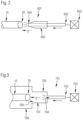
- Fig. 1A shows a glass tube 10, with a length of L, having a first end 30 and a second end 20 at the distal ends of the tube 10.
- the glass tube 10 has a circumferential wall and encloses an inner space.
- the length L is around 1.5 m, but other lengths are also possible. Lengths of 0.5 to 2.0 m are preferable as having the advantage of providing a useful length for transport as well as for further processing.
- the goal is to close both ends 20, 30 of the tube 10 and provide a ventilation hole 32 in the wall of the glass tube 10, where the ventilation hole is in the vicinity of one of the ends 20, 30.
- a first step shown in Fig. 1B , the first end 30 is closed using a closing tool 50.
- gas F is blown into the second end 20 of the glass tube by means of a gas supply 60.
- the gas F is blown into the tube 10 in the direction towards the second end 20 in the axial direction of the tube 10, so that the gas F enters the inner space of the tube 10, and preferably fills the inner space of the tube 10.
- the start of blowing of the gas F into the second end 20 is started before the start of the closing of the first end 30.
- the gas supply 60 is stopped once the first end 30 is fully closed.
- the now closed first end is indicated as 31 in the Fig. 1B .
- the gas supply can be stopped just before the first end is fully closed.
- the ventilation hole 32 is made into the wall of the glass tube near the second end 20 of the glass tube 10, by means of an opening tool 70.
- the gas supply 60 can be stopped.
- the gas supply 60 can be kept switched on, and stopped once the ventilation hole 32 has been formed or stopped during the formation of the ventilation hole 32.
- the second end 20 of the glass tube 10 is closed, also using a closing tool 55, for example of the same type as closing tool 50 used for closing the first end 30 of the glass tube.
- the now closed second end of the tube 10 is indicated with 21.
- the third step is done within a short period of time after finishing the second step. This short period of time can for example be 5 to 15 seconds.
- the result is a glass tube 10 with both ends 21, 31 closed, with a ventilation hole 32 provided near one of the ends 21, shown in Fig. 1E .
- the ventilation hole is applied by the opening tool 70, such tools are known in the art, for using a spot burner.
- the burner is located above the glass tube when opening the hole, but other positions are also usable.
- the location of the ventilation hole is preferably near the closed end of the glass tube, as the section of the tube between the ventilation hole and the closest closed end of the glass tube can typically not be further processed.
- the gas F used is preferably a non-reactive gas, that does not interfere with the closing process or interfere with the surface of the glass tube.
- a non-reactive gas that does not interfere with the closing process or interfere with the surface of the glass tube.
- air with a low relative humidity of 5%-20% at 20C room temperature. In absolute humidity terms, the air is preferably between 0,05 to 5 g/m3.
- Other examples would be nitrogen gas, carbon dioxide gas, or a mixture thereof, also with a low relative humidity (water vapor content).
- Other non-reactive engineering gases like noble gasses like argon
- gases that are reactive in the sense that they bind with water can also be used, as the use of these also reduces the humidity of the gas.
- Blowing the gas into the glass tube during processing leads to a significant reduction or full elimination of internal contamination of the closed tube.
- the gas is filtered to prevent unwanted particles to enter the glass tube to be closed. Gas filtration methods are known in the art, for example by means of a physical filter.
- Fig. 2 an example of an embodiment of a gas supply 601 according to the invention is shown.
- the gas supply 601 is provided with an inlet 602 that is connected to a gas source 603, that provides the gas F under pressure.
- a gas source 603 can be provided with a gas pressure regulator that regulates the pressure of the gas to be supplied as well as an opening and closing mechanism that can open and close the gas source.
- gas sources are well known in the art.
- the gas source can also comprise a flow meter.
- the inlet 602 is communicatively connected to an outlet 604 where the gas F leaves the gas supply 601 to enter the open end of the glass tube.
- the gas supply comprises a nozzle 605.
- the outlet 604 of the nozzle 605 is placed so that the gas F expelled from the outlet 604 of the nozzle 605 can enter the tube end 20 of the tube 10.
- the nozzle 605 is lined up with the axial direction of the tube 10.
- the outlet 604 of the nozzle 605 is place at some distance from the tube end 20 to enable the gas F to freely enter the glass tube 10.
- the gas supply 701 comprises an outlet 704 that expels the gas F into a distribution chamber 707.
- This distribution chamber 707 is preferably made as a cylindrical chamber with an open end 709 at the end facing away from the outlet 704, with the outlet 704 placed in or near the center of the chamber 707 at the closed end of the chamber.
- the open end 709 of the distribution chamber 707 is placed near or around the end 20 of the glass tube 10, so that the gas F leaving the outlet 704 and being gathered into the distribution chamber 707 can enter the glass tube 10 freely.
- a circumferential shield 708 can be placed around the open end 709 of the distribution chamber 707 .
- the shield 708 extends during the supply of gas F to the glass tube 10 around the end section 20 of the tube 10.
- the shield 708 creates a chamber that retains the gas F in a overpressure situation (compared to the ambient air pressure) so that the ambient air is prevented from entering the glass tube 10, or at least the amount of ambient air entering is reduced.
- the circumference of the shield 708 is preferably larger in diameter than the open end 709 of the distribution chamber 707.
- the shield 708 does not need to be contiguous around the circumference and can be provided with additional openings to change gas flow to improve the flow of the gas F so that it easily enters the glass tube 10.
- the invention can also be implemented by adding an air supply according to the invention to an existing closing apparatus.
- the air supply should be added to the existing apparatus so that the air supply lines up with the end of the tube at the point where the end is going to be closed.
Landscapes
- Chemical & Material Sciences (AREA)
- Engineering & Computer Science (AREA)
- Materials Engineering (AREA)
- Organic Chemistry (AREA)
- Manufacturing & Machinery (AREA)
- Re-Forming, After-Treatment, Cutting And Transporting Of Glass Products (AREA)
- Medical Preparation Storing Or Oral Administration Devices (AREA)
Abstract
Description
- The present invention relates to a method and an apparatus for the sealing of glass tubes in a hot softened state, especially of glass tubes, which are intended for the production of primary packaging means made of glass for the storage of pharmaceutically active substances.
- In the production of glass tubes usually glass tubes are severed from the glass tube line produced with for example a Vello or Danner process, which are then processed further. These glass tubes may have standard lengths of e.g., 1.5 m, but may also be severed off in other lengths in order to be processed directly to primary packaging means for the storage of pharmaceutical substances, for example, glass ampoules, glass vials, glass cartridges or glass syringes. For such applications, it is preferable that no impurities reach the interior of the glass tubes in the course of processing and handling, as these can be removed from it again only with considerable effort. Therefore, the tube ends are severed off in a hot softened state directly at the glass tubing in a special tube end processing machine and the tubes are sealed therewith to prevent a deposition of particles inside the glass tube during further processing or transport.
- Glass tubes as described above are preferred for further processing like the production of primary packaging for pharmaceutical substances, as due to the closure at both ends, the glass tubes are very robust and can withstand a lot of handling abuse without breaking. This is highly desirable for transport and further processing as loss to unintended damage is highly reduced.
- These glass tubes are provided with both ends closed as well as a ventilation hole made in the wall of the glass tube near one of the closed ends. The ventilation hole ensures that no problems occur due to variations in gas pressure during transport and storage.
- Methods for producing closed tubes are known in the art, for example from
US 9458045 EP4023615 . However, these known methods result in closed glass tubes that from time to time exhibit internal contamination with residues, also sometimes called snowflakes, that show up immediately after production or also sometimes several days or weeks after production for example during storage or transport. This kind of contamination is detrimental to further processing of the tube and requires either rejection of the tube for further processing or additional cleaning steps. It is therefore an object of the invention to provide for a method and apparatus for the production of closed glass tubes that result in reliable contamination free closed glass tubes. - Details of the invention will be described in the following under reference to the figures in which;
-
Fig. 1A-1E show schematically method steps according to the invention, -
Fig. 2 shows an example of an embodiment of a gas supply, and -
Fig. 3 shows a further example of an embodiment of a gas supply. - The process of manufacturing a glass tube according to a first embodiment will be shown in reference to
Fig. 1 A-E. Fig. 1A shows aglass tube 10, with a length of L, having afirst end 30 and asecond end 20 at the distal ends of thetube 10. Theglass tube 10 has a circumferential wall and encloses an inner space. In this example the length L is around 1.5 m, but other lengths are also possible. Lengths of 0.5 to 2.0 m are preferable as having the advantage of providing a useful length for transport as well as for further processing. - The goal is to close both
ends tube 10 and provide aventilation hole 32 in the wall of theglass tube 10, where the ventilation hole is in the vicinity of one of theends - In a first step, shown in
Fig. 1B , thefirst end 30 is closed using aclosing tool 50. During the closing of the first end, gas F is blown into thesecond end 20 of the glass tube by means of agas supply 60. The gas F is blown into thetube 10 in the direction towards thesecond end 20 in the axial direction of thetube 10, so that the gas F enters the inner space of thetube 10, and preferably fills the inner space of thetube 10. In a variant of this step, the start of blowing of the gas F into thesecond end 20 is started before the start of the closing of thefirst end 30. Thegas supply 60 is stopped once thefirst end 30 is fully closed. The now closed first end is indicated as 31 in theFig. 1B . In a variant of this step, the gas supply can be stopped just before the first end is fully closed. - In the second step, shown in
Fig. 1C , theventilation hole 32 is made into the wall of the glass tube near thesecond end 20 of theglass tube 10, by means of anopening tool 70. During this step thegas supply 60 can be stopped. In an alternative variant, thegas supply 60 can be kept switched on, and stopped once theventilation hole 32 has been formed or stopped during the formation of theventilation hole 32. - In the third step, shown in
Fig. 1D , thesecond end 20 of theglass tube 10 is closed, also using aclosing tool 55, for example of the same type asclosing tool 50 used for closing thefirst end 30 of the glass tube. The now closed second end of thetube 10 is indicated with 21. Preferably, the third step is done within a short period of time after finishing the second step. This short period of time can for example be 5 to 15 seconds. - After the third step, the result is a
glass tube 10 with bothends ventilation hole 32 provided near one of theends 21, shown inFig. 1E . By having provided gas F into thetube 10 as described above during the closing of thefirst end 30, the resulting closedtube 10 does not show internal contamination, also after a longer period of storage. - Methods and devices for closing ends of glass tubes as mentioned before as the use of a closing tool to close the end of the glass tube are known in the art, for example from
US 10315946 - The ventilation hole is applied by the
opening tool 70, such tools are known in the art, for using a spot burner. Preferably, the burner is located above the glass tube when opening the hole, but other positions are also usable. The location of the ventilation hole is preferably near the closed end of the glass tube, as the section of the tube between the ventilation hole and the closest closed end of the glass tube can typically not be further processed. - The gas F used is preferably a non-reactive gas, that does not interfere with the closing process or interfere with the surface of the glass tube. One example is air, with a low relative humidity of 5%-20% at 20C room temperature. In absolute humidity terms, the air is preferably between 0,05 to 5 g/m3. Other examples would be nitrogen gas, carbon dioxide gas, or a mixture thereof, also with a low relative humidity (water vapor content). Other non-reactive engineering gases (like noble gasses like argon) can be used, preferably with a water content (i.e. humidity) within the range of 5%-20% at 20C room temperature. Gasses that are reactive in the sense that they bind with water can also be used, as the use of these also reduces the humidity of the gas. Blowing the gas into the glass tube during processing leads to a significant reduction or full elimination of internal contamination of the closed tube. Preferably, the gas is filtered to prevent unwanted particles to enter the glass tube to be closed. Gas filtration methods are known in the art, for example by means of a physical filter.
- In
Fig. 2 an example of an embodiment of agas supply 601 according to the invention is shown. In this embodiment, thegas supply 601 is provided with aninlet 602 that is connected to agas source 603, that provides the gas F under pressure. This can for example be done using a gas compressor. Thegas source 603 can be provided with a gas pressure regulator that regulates the pressure of the gas to be supplied as well as an opening and closing mechanism that can open and close the gas source. Such gas sources are well known in the art. The gas source can also comprise a flow meter. - The
inlet 602 is communicatively connected to anoutlet 604 where the gas F leaves thegas supply 601 to enter the open end of the glass tube. In the embodiment shown infig. 2 , the gas supply comprises anozzle 605. Theoutlet 604 of thenozzle 605 is placed so that the gas F expelled from theoutlet 604 of thenozzle 605 can enter thetube end 20 of thetube 10. Preferably, thenozzle 605 is lined up with the axial direction of thetube 10. Theoutlet 604 of thenozzle 605 is place at some distance from thetube end 20 to enable the gas F to freely enter theglass tube 10. - In the embodiment shown in
fig. 3 , thegas supply 701 comprises anoutlet 704 that expels the gas F into adistribution chamber 707. Thisdistribution chamber 707 is preferably made as a cylindrical chamber with anopen end 709 at the end facing away from theoutlet 704, with theoutlet 704 placed in or near the center of thechamber 707 at the closed end of the chamber. Theopen end 709 of thedistribution chamber 707 is placed near or around theend 20 of theglass tube 10, so that the gas F leaving theoutlet 704 and being gathered into thedistribution chamber 707 can enter theglass tube 10 freely. Around theopen end 709 of the distribution chamber 707 acircumferential shield 708 can be placed. Theshield 708 extends during the supply of gas F to theglass tube 10 around theend section 20 of thetube 10. Theshield 708 creates a chamber that retains the gas F in a overpressure situation (compared to the ambient air pressure) so that the ambient air is prevented from entering theglass tube 10, or at least the amount of ambient air entering is reduced. The circumference of theshield 708 is preferably larger in diameter than theopen end 709 of thedistribution chamber 707. Theshield 708 does not need to be contiguous around the circumference and can be provided with additional openings to change gas flow to improve the flow of the gas F so that it easily enters theglass tube 10. - The invention can also be implemented by adding an air supply according to the invention to an existing closing apparatus. In that case, the air supply should be added to the existing apparatus so that the air supply lines up with the end of the tube at the point where the end is going to be closed.
Claims (9)
- Method for the manufacture of a glass tube with closed ends, comprising the steps ofProviding a glass tube (19) with open ends (20,30),Closing a first open end (30) while introducing a gas (F) into the tube (10) through the second open end (20),opening a ventilation hole (32) in a wall of the glass tube (10) near one of the open ends (20), andclosing the second open end (21).
- Method according to claim 1, wherein the gas (F) introduced has a relative humidity of 5%-20%.
- Method according to any of the preceding claims, wherein the gas (F) is introduced by means of a distribution chamber (707) located near the second open end.
- Method according to claim 3, wherein the distribution chamber (707) is located axially with respect to the glass tube (10).
- Method according to according to claim 3 or 4, wherein the distribution chamber (707) is formed by a gas exit and a three-sided open chamber enclosing at least part of the second open end.
- Method according to according to claim 1 or 2, wherein the gas (F) is introduced by means of a nozzle (605) located near the second open end.
- Method according to any of the preceding claims, wherein the gas (F) is air.
- Closed glass tube manufactured using a method according to any of the proceeding claims.
- Apparatus for closing a glass tube comprisinga glass tube transport for transporting the glass tube,a first close tool,a ventilation hole tool,a second close tool, and an air supply, wherein the air supply is positioned opposite from the first close tool.
Priority Applications (3)
| Application Number | Priority Date | Filing Date | Title |
|---|---|---|---|
| EP23199977.2A EP4530265B1 (en) | 2023-09-27 | 2023-09-27 | Method and apparatus for the production of glass tubes with closed ends |
| US18/893,054 US20250100920A1 (en) | 2023-09-27 | 2024-09-23 | Method and apparatus for the production of glass tubes with closed ends |
| CN202411325319.1A CN119707260A (en) | 2023-09-27 | 2024-09-23 | Method and device for producing a glass tube with a closed end |
Applications Claiming Priority (1)
| Application Number | Priority Date | Filing Date | Title |
|---|---|---|---|
| EP23199977.2A EP4530265B1 (en) | 2023-09-27 | 2023-09-27 | Method and apparatus for the production of glass tubes with closed ends |
Publications (2)
| Publication Number | Publication Date |
|---|---|
| EP4530265A1 true EP4530265A1 (en) | 2025-04-02 |
| EP4530265B1 EP4530265B1 (en) | 2026-03-25 |
Family
ID=88204210
Family Applications (1)
| Application Number | Title | Priority Date | Filing Date |
|---|---|---|---|
| EP23199977.2A Active EP4530265B1 (en) | 2023-09-27 | 2023-09-27 | Method and apparatus for the production of glass tubes with closed ends |
Country Status (3)
| Country | Link |
|---|---|
| US (1) | US20250100920A1 (en) |
| EP (1) | EP4530265B1 (en) |
| CN (1) | CN119707260A (en) |
Citations (6)
| Publication number | Priority date | Publication date | Assignee | Title |
|---|---|---|---|---|
| US9458045B2 (en) | 2012-09-27 | 2016-10-04 | Schott Ag | Method and apparatus for the sealing of glass tubes in a hot softened state |
| US10315946B2 (en) | 2015-02-23 | 2019-06-11 | Schott Schweiz Ag | Device and method for forming glass bodies |
| EP3502066A1 (en) * | 2016-08-16 | 2019-06-26 | Nippon Electric Glass Co., Ltd. | Glass tube production method |
| US20190322565A1 (en) * | 2018-04-24 | 2019-10-24 | Schott Ag | Method and apparatus for producing hollow glass body products, and hollow glass body products and their use |
| EP4023615A1 (en) | 2019-12-25 | 2022-07-06 | Nippon Electric Glass Co., Ltd. | Glass article manufacturing device and glass article manufacturing method |
| US20230167013A1 (en) * | 2021-11-29 | 2023-06-01 | Schott Ag | Glass tube for pharmaceutical containers and process for the production of a glass tube |
-
2023
- 2023-09-27 EP EP23199977.2A patent/EP4530265B1/en active Active
-
2024
- 2024-09-23 CN CN202411325319.1A patent/CN119707260A/en active Pending
- 2024-09-23 US US18/893,054 patent/US20250100920A1/en active Pending
Patent Citations (6)
| Publication number | Priority date | Publication date | Assignee | Title |
|---|---|---|---|---|
| US9458045B2 (en) | 2012-09-27 | 2016-10-04 | Schott Ag | Method and apparatus for the sealing of glass tubes in a hot softened state |
| US10315946B2 (en) | 2015-02-23 | 2019-06-11 | Schott Schweiz Ag | Device and method for forming glass bodies |
| EP3502066A1 (en) * | 2016-08-16 | 2019-06-26 | Nippon Electric Glass Co., Ltd. | Glass tube production method |
| US20190322565A1 (en) * | 2018-04-24 | 2019-10-24 | Schott Ag | Method and apparatus for producing hollow glass body products, and hollow glass body products and their use |
| EP4023615A1 (en) | 2019-12-25 | 2022-07-06 | Nippon Electric Glass Co., Ltd. | Glass article manufacturing device and glass article manufacturing method |
| US20230167013A1 (en) * | 2021-11-29 | 2023-06-01 | Schott Ag | Glass tube for pharmaceutical containers and process for the production of a glass tube |
Also Published As
| Publication number | Publication date |
|---|---|
| EP4530265B1 (en) | 2026-03-25 |
| US20250100920A1 (en) | 2025-03-27 |
| CN119707260A (en) | 2025-03-28 |
Similar Documents
| Publication | Publication Date | Title |
|---|---|---|
| US5609666A (en) | Process of producing preforms for silica glass optical waveguides while flowing gas through a tubular substrate | |
| US5026413A (en) | Process for manufacturing quartz glass pipes having a high content of silica with only minor diameter deviations | |
| CN101479520B (en) | Low release rate cylinder components | |
| EP4530265B1 (en) | Method and apparatus for the production of glass tubes with closed ends | |
| EP3502066B1 (en) | Glass tube production method | |
| JP2019513891A (en) | Method and apparatus for purifying target material for EUV light source | |
| US6497118B1 (en) | Method and apparatus for reducing refractory contamination in fused silica processes | |
| WO2009144071A1 (en) | Arrangement and method for removing alkali- or alkaline earth-metals from a vacuum coating chamber | |
| JP2002068770A (en) | Dehydration sintering furnace and dehydration sintering method for optical fiber preform | |
| RU2179159C2 (en) | Method of cutting down number of bubbles in glass product (variants) and glass product | |
| WO2005000752A1 (en) | Method and apparatus for producing base material of optical fiber | |
| WO2022104284A1 (en) | Apparatus and method for producing hollow quartz cylinders | |
| US7666248B2 (en) | Method of priming filter for molten metal | |
| CN108642418B (en) | Automatic detection control system and method for purging in annealing of copper pipe of well-type annealing furnace | |
| JPH01166457A (en) | Analyzer using charged particle | |
| CN111559858B (en) | Method of making optical fiber glass substrate | |
| US20010047666A1 (en) | Method of production of porous glass base material for optical fiber | |
| US6600769B2 (en) | Device and method for manufacturing a preform | |
| CN216039287U (en) | Optical fiber perform preparation device capable of avoiding tube wall collapse | |
| EP3696148B1 (en) | Fabrication method for porous glass base material for optical fiber | |
| US6029476A (en) | Method and apparatus for manufacturing an optical fiber provided with a hermetic coating | |
| JP7397169B2 (en) | Optical fiber base material manufacturing method and heating furnace | |
| JP4761355B2 (en) | Method for producing metal element-doped large quartz glass member and metal element-doped large quartz glass member obtained by the production method | |
| JPS5836936A (en) | Production of tubular vessel and ampule | |
| JPH08283031A (en) | Production of glass tube |
Legal Events
| Date | Code | Title | Description |
|---|---|---|---|
| PUAI | Public reference made under article 153(3) epc to a published international application that has entered the european phase |
Free format text: ORIGINAL CODE: 0009012 |
|
| STAA | Information on the status of an ep patent application or granted ep patent |
Free format text: STATUS: THE APPLICATION HAS BEEN PUBLISHED |
|
| AK | Designated contracting states |
Kind code of ref document: A1 Designated state(s): AL AT BE BG CH CY CZ DE DK EE ES FI FR GB GR HR HU IE IS IT LI LT LU LV MC ME MK MT NL NO PL PT RO RS SE SI SK SM TR |
|
| STAA | Information on the status of an ep patent application or granted ep patent |
Free format text: STATUS: REQUEST FOR EXAMINATION WAS MADE |
|
| 17P | Request for examination filed |
Effective date: 20250624 |
|
| P01 | Opt-out of the competence of the unified patent court (upc) registered |
Free format text: CASE NUMBER: APP_31680/2025 Effective date: 20250701 |
|
| GRAP | Despatch of communication of intention to grant a patent |
Free format text: ORIGINAL CODE: EPIDOSNIGR1 |
|
| STAA | Information on the status of an ep patent application or granted ep patent |
Free format text: STATUS: GRANT OF PATENT IS INTENDED |
|
| INTG | Intention to grant announced |
Effective date: 20251202 |
|
| GRAS | Grant fee paid |
Free format text: ORIGINAL CODE: EPIDOSNIGR3 |
|
| GRAA | (expected) grant |
Free format text: ORIGINAL CODE: 0009210 |
|
| STAA | Information on the status of an ep patent application or granted ep patent |
Free format text: STATUS: THE PATENT HAS BEEN GRANTED |
|
| AK | Designated contracting states |
Kind code of ref document: B1 Designated state(s): AL AT BE BG CH CY CZ DE DK EE ES FI FR GB GR HR HU IE IS IT LI LT LU LV MC ME MK MT NL NO PL PT RO RS SE SI SK SM TR |
|
| REG | Reference to a national code |
Ref country code: CH Ref legal event code: F10 Free format text: ST27 STATUS EVENT CODE: U-0-0-F10-F00 (AS PROVIDED BY THE NATIONAL OFFICE) Effective date: 20260325 Ref country code: GB Ref legal event code: FG4D |
|
| REG | Reference to a national code |
Ref country code: DE Ref legal event code: R096 Ref document number: 602023013989 Country of ref document: DE |
|
| REG | Reference to a national code |
Ref country code: IE Ref legal event code: FG4D |