EP4530212A2 - Reissverschlussanordnung und verfahren zur herstellung davon - Google Patents
Reissverschlussanordnung und verfahren zur herstellung davon Download PDFInfo
- Publication number
- EP4530212A2 EP4530212A2 EP24198311.3A EP24198311A EP4530212A2 EP 4530212 A2 EP4530212 A2 EP 4530212A2 EP 24198311 A EP24198311 A EP 24198311A EP 4530212 A2 EP4530212 A2 EP 4530212A2
- Authority
- EP
- European Patent Office
- Prior art keywords
- flange
- tear strip
- zipper assembly
- enclosure
- panel
- Prior art date
- Legal status (The legal status is an assumption and is not a legal conclusion. Google has not performed a legal analysis and makes no representation as to the accuracy of the status listed.)
- Pending
Links
Images




Classifications
-
- B—PERFORMING OPERATIONS; TRANSPORTING
- B65—CONVEYING; PACKING; STORING; HANDLING THIN OR FILAMENTARY MATERIAL
- B65D—CONTAINERS FOR STORAGE OR TRANSPORT OF ARTICLES OR MATERIALS, e.g. BAGS, BARRELS, BOTTLES, BOXES, CANS, CARTONS, CRATES, DRUMS, JARS, TANKS, HOPPERS, FORWARDING CONTAINERS; ACCESSORIES, CLOSURES, OR FITTINGS THEREFOR; PACKAGING ELEMENTS; PACKAGES
- B65D33/00—Details of, or accessories for, sacks or bags
- B65D33/16—End- or aperture-closing arrangements or devices
- B65D33/25—Riveting; Dovetailing; Screwing; using press buttons or slide fasteners
- B65D33/2508—Riveting; Dovetailing; Screwing; using press buttons or slide fasteners using slide fasteners with interlocking members having a substantially uniform section throughout the length of the fastener; Sliders therefor
- B65D33/2516—Riveting; Dovetailing; Screwing; using press buttons or slide fasteners using slide fasteners with interlocking members having a substantially uniform section throughout the length of the fastener; Sliders therefor comprising tamper-indicating means, e.g. located within the fastener
- B65D33/2533—Riveting; Dovetailing; Screwing; using press buttons or slide fasteners using slide fasteners with interlocking members having a substantially uniform section throughout the length of the fastener; Sliders therefor comprising tamper-indicating means, e.g. located within the fastener the slide fastener being located between the product compartment and the tamper indicating means
-
- B—PERFORMING OPERATIONS; TRANSPORTING
- B65—CONVEYING; PACKING; STORING; HANDLING THIN OR FILAMENTARY MATERIAL
- B65D—CONTAINERS FOR STORAGE OR TRANSPORT OF ARTICLES OR MATERIALS, e.g. BAGS, BARRELS, BOTTLES, BOXES, CANS, CARTONS, CRATES, DRUMS, JARS, TANKS, HOPPERS, FORWARDING CONTAINERS; ACCESSORIES, CLOSURES, OR FITTINGS THEREFOR; PACKAGING ELEMENTS; PACKAGES
- B65D33/00—Details of, or accessories for, sacks or bags
- B65D33/16—End- or aperture-closing arrangements or devices
- B65D33/25—Riveting; Dovetailing; Screwing; using press buttons or slide fasteners
- B65D33/2508—Riveting; Dovetailing; Screwing; using press buttons or slide fasteners using slide fasteners with interlocking members having a substantially uniform section throughout the length of the fastener; Sliders therefor
- B65D33/2541—Riveting; Dovetailing; Screwing; using press buttons or slide fasteners using slide fasteners with interlocking members having a substantially uniform section throughout the length of the fastener; Sliders therefor characterised by the slide fastener, e.g. adapted to interlock with a sheet between the interlocking members having sections of particular shape
-
- B—PERFORMING OPERATIONS; TRANSPORTING
- B65—CONVEYING; PACKING; STORING; HANDLING THIN OR FILAMENTARY MATERIAL
- B65D—CONTAINERS FOR STORAGE OR TRANSPORT OF ARTICLES OR MATERIALS, e.g. BAGS, BARRELS, BOTTLES, BOXES, CANS, CARTONS, CRATES, DRUMS, JARS, TANKS, HOPPERS, FORWARDING CONTAINERS; ACCESSORIES, CLOSURES, OR FITTINGS THEREFOR; PACKAGING ELEMENTS; PACKAGES
- B65D33/00—Details of, or accessories for, sacks or bags
- B65D33/16—End- or aperture-closing arrangements or devices
- B65D33/25—Riveting; Dovetailing; Screwing; using press buttons or slide fasteners
- B65D33/2508—Riveting; Dovetailing; Screwing; using press buttons or slide fasteners using slide fasteners with interlocking members having a substantially uniform section throughout the length of the fastener; Sliders therefor
- B65D33/2575—Riveting; Dovetailing; Screwing; using press buttons or slide fasteners using slide fasteners with interlocking members having a substantially uniform section throughout the length of the fastener; Sliders therefor the slide fastener providing access to the bag through a bag wall, e.g. intended to be cut open by the consumer
-
- B—PERFORMING OPERATIONS; TRANSPORTING
- B65—CONVEYING; PACKING; STORING; HANDLING THIN OR FILAMENTARY MATERIAL
- B65D—CONTAINERS FOR STORAGE OR TRANSPORT OF ARTICLES OR MATERIALS, e.g. BAGS, BARRELS, BOTTLES, BOXES, CANS, CARTONS, CRATES, DRUMS, JARS, TANKS, HOPPERS, FORWARDING CONTAINERS; ACCESSORIES, CLOSURES, OR FITTINGS THEREFOR; PACKAGING ELEMENTS; PACKAGES
- B65D77/00—Packages formed by enclosing articles or materials in preformed containers, e.g. boxes, cartons, sacks or bags
- B65D77/22—Details
- B65D77/30—Opening or contents-removing devices added or incorporated during filling or closing of containers
- B65D77/32—Tearing-strings or like flexible elements
Definitions
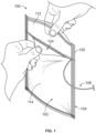
- enclosures include recloseable zipper assemblies to allow users to repeatedly open and close the enclosures.
- plastic bags may have zipper assemblies with opposing profiles formed from intermeshing or interlocking elements. These elements may be bodies having complimentary or matching shapes to allow the profiles to interlock with each other to close the enclosure. A user may pull the profiles away from each other with sufficient force to separate the elements to open the enclosure.
- the zipper assemblies can be coupled with the enclosures by attaching opposite sides of the profiles with panels of the enclosures.
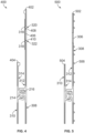
- the inner side 218 of the tear strip 106 may be coextensive or coplanar with the facing side 210 of the flange 202, as shown in Figure 2 .
- the panel side 220 of the tear strip 106 may project or protrude from the panel side 206 of the flange 202.
- the inner side 218 of the tear strip 106 may project or protrude from the facing side 210 of the flange 202 with the panel side 220 of the tear strip 106 being coplanar or coextensive with the panel side 206 of the flange 202.
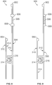
- the zipper assembly 600 includes opposing flanges 602, 604, or base parts, that face each other and that are sealed to the inner surfaces of the front and back panels 102, 104 of the enclosure 100.
- Each flange 602, 604 can have the panel side 308, 310 that faces and is sealed to a different one of the panels 102, 104 and the facing side 312, 314 that faces away from the panel 102 or 104 to which the flange 602, 604 is coupled but faces toward the facing side 312 or 314 of the other flange 602 or 604.
- Each of the flanges 602, 604 includes the interlocking body 214, 216 described above protruding from the facing side 312, 314 of that flange 602, 604.
- the flange 602 is shown as including the tear strip 306, but alternatively, the flange 604 may have the tear strip 306.
- the tear strip 306 may be the same thickness as the majority of the flange 602, may be thinner than the majority of the flange 602, or may be thicker than the majority of the flange 602.
- the zipper assembly 600 may not include the gaps between the flange 602 and the tear strip 306 and/or may not include the thin portion or connecting web described above. Alternatively, the zipper assembly 600 may include the gaps and/or the thin portion or connecting web.
- the flange 602 having the tear strip 306 may include protruding portions or rails 606, 608 that extend or protrude from the panel side 308 of the flange 602.
- the protruding portions 606, 608 may be disposed on opposite sides of the opposite edges of the tear strip 306.
- the protruding portions 606, 608 may be thicker than the rest of the flange 602 (but for the interlocking element or body 214 and/or 216) and the tear strip 306 but may only protrude from the panel side 308 of the flange 602.
- the protruding portions 606, 608 may have a small width relative to the rest of the flange 602.
- the widths of different components may be measured along distances extending along or parallel to the panel sides 308, 310 and/or the facing sides 312, 314.
- the width of each of the protruding portions 606, 608 may be smaller than the width of the tear strip 306, smaller than the rest of the flange 602, 604, and/or smaller than the width of each of the interlocking bodies 214, 216.
- the protruding portions 606, 608 may contact the tear strip 306.
- the opposite edges of the tear strip 306 may directly abut the protruding portions 606, 608 without any other materials or components between the tear strip 306 and the protruding portions 606, 608.
- one or more materials e.g., peel seal material, heat seal material, another adhesive, etc.
- gaps may be present between the edges of the tear strip 306 and the protruding portions 606, 608.
- the protruding portions 606, 608 may be stronger or stiffer than the remainder of the flange 602. For example, the protruding portions 606, 608 may be more difficult or require more force to tear than the flange 602.
- the protruding portions 606, 608 can both help guide pulling of the tear strip 306 in locations between the protruding portions 606, 608 and prevent the tear strip 306 from tearing the flange 602.
- Figure 7 illustrates a cross-sectional view of another example of a zipper assembly 700.
- the zipper assembly 700 can represent or be used in place of the zipper assembly 200, 300, 400, 500, and/or 600 in the enclosure 100 shown in Figure 1 .
- the zipper assembly 700 may be coupled with inside or inner surfaces of the front and/or back panels 102 and/or 104 of the enclosure 100.
- the zipper assembly 700 can include the tear strip 306 described above.
- the zipper assembly 700 may be opened below the opening formed by the tear strip, as described above.
- the zipper assembly 700 includes opposing flanges 702, 704, or base parts, that face each other and that are sealed to the inner surfaces of the front and back panels 102, 104 of the enclosure 100.
- Each flange 702, 704 can have the panel side 308, 310 that faces and is sealed to a different one of the panels 102, 104 and the facing side 312, 314 that faces away from the panel 102 or 104 to which the flange 702, 704 is coupled but faces toward the facing side 312 or 314 of the other flange 702 or 704.
- Each of the flanges 702, 704 includes the interlocking body 214, 216 described above protruding from the facing side 312, 314 of that flange 702, 704.
- the flange 702 is shown as including the tear strip 306, but alternatively, the flange 704 may have the tear strip 306.
- the tear strip 306 may be the same thickness as the majority of the flange 702, may be thinner than the majority of the flange 702, or may be thicker than the majority of the flange 702.
- the zipper assembly 700 may not include the gaps between the flange 702 and the tear strip 306 and/or may not include the thin portion or connecting web described above. Alternatively, the zipper assembly 700 may include the gaps and/or the thin portion or connecting web.
- the flange 702 having the tear strip 306 may include protruding portions or rails 706, 708 that extend or protrude from the facing side 312 of the flange 702.
- the protruding portions 706, 708 may be disposed on opposite sides of the opposite edges of the tear strip 306.
- the protruding portions 706, 708 may be thicker than the rest of the flange 702 (but for the interlocking element or body 214 and/or 216) and the tear strip 306 but may only protrude from the facing side 312 of the flange 702.
- the protruding portions 706, 708 may have a small width relative to the rest of the flange 702.
- the width of each of the protruding portions 706, 708 may be smaller than the width of the tear strip 306, smaller than the rest of the flange 702, 704, and/or smaller than the width of each of the interlocking bodies 214, 216.
- the protruding portions 706, 708 may contact the tear strip 306.
- the opposite edges of the tear strip 306 may directly abut the protruding portions 706, 708 without any other materials or components between the tear strip 306 and the protruding portions 706, 708.
- one or more materials e.g., peel seal material, heat seal material, another adhesive, etc.
- gaps may be present between the edges of the tear strip 306 and the protruding portions 706, 708.
- the protruding portions 706, 708 may be stronger or stiffer than the remainder of the flange 702. For example, the protruding portions 706, 708 may be more difficult or require more force to tear than the flange 702.
- the protruding portions 706, 708 can both help guide pulling of the tear strip 306 in locations between the protruding portions 706, 708 and prevent the tear strip 306 from tearing the flange 702.
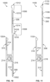
- Figure 8 illustrates a cross-sectional view of another example of a zipper assembly 800.
- the zipper assembly 800 can represent or be used in place of the zipper assembly 200, 300, 400, 500, 600, and/or 700 in the enclosure 100 shown in Figure 1 .
- the zipper assembly 800 may be coupled with inside or inner surfaces of the front and/or back panels 102 and/or 104 of the enclosure 100.
- the zipper assembly 800 can include the tear strip 306 described above.
- the zipper assembly 800 may be opened below the opening formed by the tear strip, as described above.
- the zipper assembly 800 includes opposing flanges 802, 804, or base parts, that face each other and that are sealed to the inner surfaces of the front and back panels 102, 104 of the enclosure 100.
- Each flange 802, 804 can have the panel side 308, 310 that faces and is sealed to a different one of the panels 102, 104 and the facing side 312, 314 that faces away from the panel 102 or 104 to which the flange 802, 804 is coupled but faces toward the facing side 312 or 314 of the other flange 802 or 804.
- Each of the flanges 802, 804 includes the interlocking body 214, 216 described above protruding from the facing side 312, 314 of that flange 802, 804.
- the flange 802 is shown as including the tear strip 306, but alternatively, the flange 804 may have the tear strip 306.
- the tear strip 306 may be the same thickness as the majority of the flange 802, may be thinner than the majority of the flange 802, or may be thicker than the majority of the flange 802.
- the zipper assembly 800 may not include the gaps between the flange 802 and the tear strip 306 and/or may not include the thin portion or connecting web described above. Alternatively, the zipper assembly 800 may include the gaps and/or the thin portion or connecting web.
- the flange 802 having the tear strip 306 may include protruding portions or rails 806, 808 that extend or protrude from the facing side 312 and from the panel side 308 of the flange 802.
- the protruding portions 806, 808 may be disposed on opposite sides of the opposite edges of the tear strip 306.
- the protruding portions 806, 808 may be thicker than the rest of the flange 802 (but for the interlocking element or body 214 and/or 216) and the tear strip 306 and may protrude from both the facing side 312 and the panel side 308 of the flange 802 in opposite directions.
- the protruding portions 806, 808 may have a small width relative to the rest of the flange 802.
- the width of each of the protruding portions 806, 808 may be smaller than the width of the tear strip 306, smaller than the rest of the flange 802, 804, and/or smaller than the width of each of the interlocking bodies 214, 216.
- the protruding portions 806, 808 may contact the tear strip 306.
- the opposite edges of the tear strip 306 may directly abut the protruding portions 806, 808 without any other materials or components between the tear strip 306 and the protruding portions 806, 808.
- one or more materials e.g., peel seal material, heat seal material, another adhesive, etc.
- gaps may be present between the edges of the tear strip 306 and the protruding portions 806, 808.
- the protruding portions 806, 808 may be stronger or stiffer than the remainder of the flange 802. For example, the protruding portions 806, 808 may be more difficult or require more force to tear than the flange 802.
- the protruding portions 806, 808 can both help guide pulling of the tear strip 306 in locations between the protruding portions 806, 808 and prevent the tear strip 306 from tearing the flange 802.
- Figure 9 illustrates a cross-sectional view of another example of a zipper assembly 900.
- the zipper assembly 900 can represent or be used in place of the zipper assembly 200, 300, 400, 500, 600, 700, and/or 800 in the enclosure 100 shown in Figure 1 .
- the zipper assembly 900 may be coupled with inside or inner surfaces of the front and/or back panels 102 and/or 104 of the enclosure 100.
- the zipper assembly 900 can include the tear strip 306 described above.
- the zipper assembly 900 may be opened below the opening formed by the tear strip, as described above.
- the zipper assembly 900 includes opposing flanges 902, 904, or base parts, that face each other and that are sealed to the inner surfaces of the front and back panels 102, 104 of the enclosure 100.
- Each flange 902, 904 can have the panel side 308, 310 that faces and is sealed to a different one of the panels 102, 104 and the facing side 312, 314 that faces away from the panel 102 or 104 to which the flange 902, 904 is coupled but faces toward the facing side 312 or 314 of the other flange 902 or 904.
- Each of the flanges 902, 904 includes the interlocking body 214, 216 described above protruding from the facing side 312, 314 of that flange 902, 904.
- the flange 902 is shown as including the tear strip 306, but alternatively, the flange 904 may have the tear strip 306.
- the tear strip 306 may be thicker than the majority of the flange 902.
- the zipper assembly 900 may not include the gaps between the flange 902 and the tear strip 306 and/or may not include the thin portion or connecting web described above. Alternatively, the zipper assembly 900 may include the gaps and/or the thin portion or connecting web.
- the flange 902 having the tear strip 306 may include protruding portions or rails 906, 908 that extend or protrude from the panel side 308 of the flange 902.
- the protruding portions 906, 908 may be disposed on opposite sides of the opposite edges of the tear strip 306.
- the protruding portions 906, 908 may be the same thickness as the tear strip 306 such that the opposite sides of the tear strip 306 and the opposite sides of the protruding portions 906, 908 are coextensive or coplanar with each other.
- the protruding portions 906, 908 may contact the tear strip 306.
- the opposite edges of the tear strip 306 may directly abut the protruding portions 906, 908 without any other materials or components between the tear strip 306 and the protruding portions 906, 908.
- one or more materials e.g., peel seal material, heat seal material, another adhesive, etc.
- gaps may be present between the edges of the tear strip 306 and the protruding portions 906, 908.
- the protruding portions 906, 908 may be stronger or stiffer than the remainder of the flange 902. For example, the protruding portions 906, 908 may be more difficult or require more force to tear than the flange 902.
- the protruding portions 906, 908 can both help guide pulling of the tear strip 306 in locations between the protruding portions 906, 908 and prevent the tear strip 306 from tearing the flange 902.
- the protruding portions 906, 908 having the same thickness as the tear strip 306 may assist in preventing the tear strip 306 from catching on the protruding portions 906, 908 as the tear strip 306 is pulled, especially if the tear strip 306 is pulled at an angle toward the protruding portion 906 or the protruding portion 908.
- Figure 10 illustrates a cross-sectional view of another example of a zipper assembly 1000.
- the zipper assembly 1000 can represent or be used in place of the zipper assembly 200, 300, 400, 500, 600, 700, 800, and/or 900 in the enclosure 100 shown in Figure 1 .
- the zipper assembly 1000 may be coupled with inside or inner surfaces of the front and/or back panels 102 and/or 104 of the enclosure 100.
- the zipper assembly 1000 can include the tear strip 306 described above.
- the zipper assembly 1000 may be opened below the opening formed by the tear strip, as described above.
- the zipper assembly 1000 includes opposing flanges 1002, 1004, or base parts, that face each other and that are sealed to the inner surfaces of the front and back panels 102, 104 of the enclosure 100.
- Each flange 1002, 1004 can have the panel side 308, 310 that faces and is sealed to a different one of the panels 102, 104 and the facing side 312, 314 that faces away from the panel 102 or 104 to which the flange 1002, 1004 is coupled but faces toward the facing side 312 or 314 of the other flange 1002 or 1004.
- Each of the flanges 1002, 1004 includes the interlocking body 214, 216 described above protruding from the facing side 312, 314 of that flange 1002, 1004.
- the flange 1002 is shown as including the tear strip 306, but alternatively, the flange 1004 may have the tear strip 306.
- the zipper assembly 1000 may not include the gaps between the flange 1002 and the tear strip 306 and/or may not include the thin portion or connecting web described above. Alternatively, the zipper assembly 1000 may include the gaps and/or the thin portion or connecting web.
- the flange 1002 having the tear strip 306 may include angled protruding portions or rails 1006, 1008 that extend or protrude from the panel side 308 of the flange 902.
- the protruding portions 1006, 1008 may be disposed on opposite sides of the opposite edges of the tear strip 306.
- the protruding portions 1006, 1008 may be the same thickness as the tear strip 306 such that the opposite sides of the tear strip 306 and the opposite sides of the protruding portions 1006, 1008 are coextensive or coplanar with each other.
- the protruding portions 1006, 1008 may be tapered in shape such that the protruding portions 1006, 1008 are different thicknesses in different locations.
- the protruding portion 1006 may have an angled surface 1010 that is oriented at an acute angle relative to the panel side 308 of the flange 1002.
- the protruding portion 1006 may be part of the panel side 308 and that is angled so that the flange 1002 is thinner at or closer to the tear strip 306 and thicker at or farther from the tear strip 306 (e.g., at an upper edge 1012 of the flange 1002).
- the protruding portion 1008 may have angled surfaces 1014, 1016 that also are oriented at acute angles to the panel side 308 of the flange 1002.
- the angled surfaces 1014, 1016 may intersect each other between the tear strip 306 and the interlocking element or body 214 (or 216).
- the angled surfaces 1014, 1016 may be positioned such that the flange 1002 is thinner at or closer to the tear strip 306, is thicker or thickest in locations farther from the tear strip 306 up to an intersection 1018 of the angled surfaces 1014, 1016, and becomes thinner in locations that are farther from this intersection and closer to the interlocking element or body 214 (or 216).
- the protruding portions 1006, 1008 may contact the tear strip 306.
- the opposite edges of the tear strip 306 may directly abut the protruding portions 1006, 1008 without any other materials or components between the tear strip 306 and the protruding portions 1006, 1008.
- one or more materials e.g., peel seal material, heat seal material, another adhesive, etc.
- gaps may be present between the edges of the tear strip 306 and the protruding portions 1006, 1008.
- the protruding portions 1006, 1008 may be stronger or stiffer than the remainder of the flange 1002. For example, the protruding portions 1006, 1008 may be more difficult or require more force to tear than the flange 1002.
- the protruding portions 1006, 1008 can both help guide pulling of the tear strip 306 in locations between the protruding portions 1006, 1008 and prevent the tear strip 306 from tearing the flange 1002.
- the protruding portions 1006, 1008 having the angled surfaces 1010, 1014, 1016 that are parts of the panel side 308 may assist users in locating or feeling where the tear strip 306 is located.
- Figure 11 illustrates a cross-sectional view of another example of a zipper assembly 1100.
- the zipper assembly 1100 can represent or be used in place of the zipper assembly 200, 300, 400, 500, 600, 700, 800, 900, and/or 1000 in the enclosure 100 shown in Figure 1 .
- the zipper assembly 1100 may be coupled with inside or inner surfaces of the front and/or back panels 102 and/or 104 of the enclosure 100.
- the zipper assembly 1100 can include the tear strip 306 described above.
- the zipper assembly 1100 may be opened below the opening formed by the tear strip, as described above.
- the zipper assembly 1100 includes opposing flanges 1102, 1104, or base parts, that face each other and that are sealed to the inner surfaces of the front and back panels 102, 104 of the enclosure 100.
- Each flange 1102, 1104 can have the panel side 308, 310 that faces and is sealed to a different one of the panels 102, 104 and the facing side 312, 314 that faces away from the panel 102 or 104 to which the flange 1102, 1104 is coupled but faces toward the facing side 312 or 314 of the other flange 1102 or 1104.
- Each of the flanges 1102, 1104 includes the interlocking body 214, 216 described above protruding from the facing side 312, 314 of that flange 1102, 1104.
- the flange 1102 is shown as including the tear strip 306, but alternatively, the flange 1104 may have the tear strip 306.
- the zipper assembly 1100 may not include the gaps between the flange 1102 and the tear strip 306 and/or may not include the thin portion or connecting web described above. Alternatively, the zipper assembly 1100 may include the gaps and/or the thin portion or connecting web.
- the flange 1102 having the tear strip 306 may include an additional tear strip 1106.
- the additional tear strip 1106 and the tear strip 306 may be spaced apart from each other and not contact each other. For example, a segment or section 1108 of the flange 1102 may be disposed between the tear strips 306, 1106.
- the additional tear strip 1106 may not have an exposed end, tab, or portion that is pulled by a user to tear an opening through the panel 102 of the enclosure 100. Instead, the additional tear strip 1106 may remain in the flange 1102 to help prevent the tear strip 306 from tearing through the flange 1102.
- the additional tear strip 1106 may be tougher or stronger than the flange 1102 such that, if pulling on the tear strip 306 begins tearing through the segment 1108 of the flange 1102, the additional tear strip 1106 can stop the tear from continuing or propagating through the remainder of the flange 1102 (e.g., up to an upper edge 1110 of the flange 1102).
- Figure 12 illustrates a cross-sectional view of another example of a zipper assembly 1200.
- the zipper assembly 1200 can represent or be used in place of the zipper assembly 200, 300, 400, 500, 600, 700, 800, 900, 1000, and/or 1100 in the enclosure 100 shown in Figure 1 .
- the zipper assembly 1200 may be coupled with inside or inner surfaces of the front and/or back panels 102 and/or 104 of the enclosure 100.
- the zipper assembly 1200 can include the tear strip 306 described above.
- the zipper assembly 1200 may be opened below the opening formed by the tear strip, as described above.
- the zipper assembly 1200 includes opposing flanges 1202, 1204, or base parts, that face each other and that are sealed to the inner surfaces of the front and back panels 102, 104 of the enclosure 100.
- Each flange 1202, 1204 can have the panel side 308, 310 that faces and is sealed to a different one of the panels 102, 104 and the facing side 312, 314 that faces away from the panel 102 or 104 to which the flange 1202, 1204 is coupled but faces toward the facing side 312 or 314 of the other flange 1202 or 1204.
- Each of the flanges 1202, 1204 includes the interlocking body 214, 216 described above protruding from the facing side 312, 314 of that flange 1202, 1204.
- the flange 1202 is shown as including the tear strip 306, but alternatively, the flange 1204 may have the tear strip 306.
- the zipper assembly 1200 may not include the gaps between the flange 1202 and the tear strip 306 and/or may not include the thin portion or connecting web described above. Alternatively, the zipper assembly 1200 may include the gaps and/or the thin portion or connecting web.
- the flange 1202 having the tear strip 306 may include the additional tear strip 1106 described above, as well as another additional tear strip 1206.
- the tear strips 306, 1106, 1206 may be spaced apart from each other and not contact each other.
- the flange segment or section 1108 described above may be disposed between the tear strips 306, 1106, and another flange segment or section 1208 may be disposed between the tear strips 306, 1206.
- the additional tear strip 1106 may be referred to an upper tear strip
- the additional tear strip 1206 may be referred to as a lower tear strip
- the tear strip 306 can be referred to as an intermediate, middle, or actionable tear strip.
- the upper tear strip 1106 is above the tear strip 306 between the tear strip 306 and the upper edge 1110 of the flange 1202.
- the upper tear strip 1106 is farther from the interlocking bodies or elements 214, 216 than the lower tear strip 1206.
- the lower tear strip 1206 is below the tear strip 306 between the tear strip 306 and the interlocking bodies or elements 214, 216.
- the lower tear strip 1206 is farther from the upper edge 1110 of the flange 1202.
- the lower tear strip 1206 may not have an exposed end, tab, or portion that is pulled by a user to tear an opening through the panel 102 of the enclosure 100. Instead, the lower tear strip 1206 may remain in the flange 1202 to help prevent the tear strip 306 from tearing through the flange 1202.
- the lower tear strip 1206 may be tougher or stronger than the flange 1202 such that, if pulling on the tear strip 306 begins tearing through the lower segment 1208 of the flange 1202, the lower tear strip 1206 can stop the tear from continuing or propagating through the remainder of the flange 1202 (e.g., down to or toward the interlocking bodies 214, 216).
- the upper tear strip 1106 similarly can prevent the tear strip 306 from tearing into the upper segment 1108 of the flange 1202, as described above.
- Figure 13 illustrates a cross-sectional view of another example of a zipper assembly 1300.
- the zipper assembly 1300 can represent or be used in place of the zipper assembly 200, 300, 400, 500, 600, 700, 800, 900, 1000, 1100, and/or 1200 in the enclosure 100 shown in Figure 1 .
- the zipper assembly 1300 may be coupled with inside or inner surfaces of the front and/or back panels 102 and/or 104 of the enclosure 100.
- the zipper assembly 1300 can include the tear strip 306 described above.
- the zipper assembly 1300 may be opened below the opening formed by the tear strip, as described above.
- the zipper assembly 1300 includes opposing flanges 1302, 1304, or base parts, that face each other and that are sealed to the inner surfaces of the front and back panels 102, 104 of the enclosure 100.
- Each flange 1302, 1304 can have the panel side 308, 310 that faces and is sealed to a different one of the panels 102, 104 and the facing side 312, 314 that faces away from the panel 102 or 104 to which the flange 1302, 1304 is coupled but faces toward the facing side 312 or 314 of the other flange 1302 or 1304.
- Each of the flanges 1302, 1304 includes the interlocking body 214, 216 described above protruding from the facing side 312, 314 of that flange 1302, 1304.
- the flange 1302 is shown as including the tear strip 306, but alternatively, the flange 1304 may have the tear strip 306.
- the zipper assembly 1300 may not include the gaps between the flange 1302 and the tear strip 306 and/or may not include the thin portion or connecting web described above. Alternatively, the zipper assembly 1300 may include the gaps and/or the thin portion or connecting web.
- the flanges 1302, 1304 of the zipper assembly 1300 may be of equal or approximately equal width (e.g., within manufacturing tolerances).
- the flange 1302 may extend along a width dimension from an upper edge 1306 to an opposite lower edge 1308 and the flange 1304 may extend along the width dimension from an upper edge 1310 to an opposite lower edge 1312.
- the distance along the width dimension from the upper edge 1306 to the lower edge 1308 of the flange 1302 and the distance along the width dimension from the upper edge 1310 to the lower edge 1312 of the flange 1304 may be the same or approximately the same within manufacturing tolerances.
- These equal sized flanges 1302, 1304 may help protect the tear strip 306 from the side of the flange 1304 not having the tear strip 306. Additionally, the equal sized flanges 1302, 1304 may provide for a heftier feel in a header section or top section of the enclosure 100 (when compared with other zipper assemblies not having flanges of equal height or width).
- Figure 14 illustrates a cross-sectional view of another example of a zipper assembly 1400.
- the zipper assembly 1400 can represent or be used in place of the zipper assembly 200, 300, 400, 500, 600, 700, 800, 900, 1000, 1100, 1200, and/or 1300 in the enclosure 100 shown in Figure 1 .
- the zipper assembly 1400 may be coupled with inside or inner surfaces of the front and/or back panels 102 and/or 104 of the enclosure 100.
- the zipper assembly 1400 can include the tear strip 306 described above.
- the zipper assembly 1400 may be opened below the opening formed by the tear strip, as described above.
- the zipper assembly 1400 may include a single flange or base part 1402.
- the single flange 1402 may be sealed to the inner surfaces of the front and back panels 102, 104 of the enclosure 100.
- the flange 1402 can have a single panel side 1408 that faces and is sealed to the panels 102, 104.
- the flange 1402 may include a single facing side 1412 that faces inward and toward itself. As shown, the flange 1402 extends from one edge 1404 to another edge 1406 with a bend 1414 in the flange 1402 midway or approximately midway between the edges 1404, 1406.
- the facing side 1412 of the panel 1402 can include the interlocking bodies 214, 216 described above protruding from the facing side 1412.
- the flange 1402 includes the tear strip 306 between the bend 1414 and the interlocking bodies 214, 216.
- the zipper assembly 1400 may not include the gaps between the flange 1402 and the tear strip 306 and/or may not include the thin portion or connecting web described above. Alternatively, the zipper assembly 1400 may include the gaps and/or the thin portion or connecting web.
- the single flange 1402 with the bend 1414 can provide increased resistance to unintended or undesirable entrance into the enclosure 100 through the top of the zipper assembly 1400 when compared to other zipper assemblies formed from separate flanges.
- the flange 1402 extending through and over the interlocking bodies 214, 216 at the bend 1414 can provide an additional barrier to entry into the space between the segments of the flange 1402 that oppose each other beneath the bend 1414 (relative to zipper assemblies with separate flanges).
- Figure 15 illustrates a cross-sectional view of another example of a zipper assembly 1500.
- the zipper assembly 1500 can represent or be used in place of the zipper assembly 200, 300, 400, 500, 600, 700, 800, 900, 1000, 1100, 1200, 1300, and/or 1400 in the enclosure 100 shown in Figure 1 .
- the zipper assembly 1500 may be coupled with inside or inner surfaces of the front and/or back panels 102 and/or 104 of the enclosure 100.
- the zipper assembly 1500 can include the tear strip 306 described above.
- the zipper assembly 1500 may be opened below the opening formed by the tear strip, as described above.
- the zipper assembly 1500 includes opposing flanges 1502, 1504, or base parts, that face each other and that are sealed to the inner surfaces of the front and back panels 102, 104 of the enclosure 100.
- Each flange 1502, 1504 can have the panel side 308, 310 that faces and is sealed to a different one of the panels 102, 104 and the facing side 312, 314 that faces away from the panel 102 or 104 to which the flange 1502, 1504 is coupled but faces toward the facing side 312 or 314 of the other flange 1502 or 1504.
- Each of the flanges 1502, 1504 includes the interlocking body 214, 216 described above protruding from the facing side 312, 314 of that flange 1502, 1504.
- the flange 1502 is shown as including the tear strip 306, but alternatively, the flange 1504 may have the tear strip 306.
- the zipper assembly 1500 may not include the gaps between the flange 1502 and the tear strip 306 and/or may not include the thin portion or connecting web described above. Alternatively, the zipper assembly 1500 may include the gaps and/or the thin portion or connecting web.
- the flanges 1502, 1504 may be of equal or approximately equal width like the flanges 1302, 1304 of the zipper assembly 1300 shown in Figure 13 .
- the flanges 1502, 1502 may be sealed to each other at or near upper edges 1508, 1510 of the flanges 1302, 1304 using a seal 1506, such as an adhesive (e.g., a heat seal material).
- the opposite lower edges 1512, 1514 of the flanges 1502, 1504 may remain separate.
- These equal sized flanges 1502, 1504 may help protect the tear strip 306 from the side of the flange 1504 not having the tear strip 306.
- the equal sized flanges 1502, 1504 may provide for a heftier feel in a header section or top section of the enclosure 100 (when compared with other zipper assemblies not having flanges of equal height or width).
- the seal 1506 between the flanges 1502, 1504 can provide increased resistance to unintended or undesirable entrance into the enclosure 100 through the top of the zipper assembly 1500 when compared to other zipper assemblies formed from separate flanges.
- the seal 1506 can provide an additional barrier to entry into the space between the flanges 1502, 1504 (relative to zipper assemblies with separate flanges).
- Figure 16 illustrates a cross-sectional view of another example of a zipper assembly 1600.
- the zipper assembly 1600 can represent or be used in place of the zipper assembly 200, 300, 400, 500, 600, 700, 800, 900, 1000, 1100, 1200, 1300, 1400, and/or 1500 in the enclosure 100 shown in Figure 1 .
- the zipper assembly 1600 may be coupled with inside or inner surfaces of the front and/or back panels 102 and/or 104 of the enclosure 100.
- the zipper assembly 1600 can include the tear strip 306 described above.
- the zipper assembly 1600 may be opened below the opening formed by the tear strip, as described above.
- the zipper assembly 1600 includes opposing flanges 1602, 1604, or base parts, that face each other and that are sealed to the inner surfaces of the front and/or back panels 102 and/or 104 of the enclosure 100.
- each flange 1602, 1604 may be sealed to the inner surface of a different panel 102, 104, or both flanges 1602, 1604 may be sealed to one panel 102 or 104, and only the other flange (e.g., flange 1602) is sealed to the other panel 104 or 102.
- Each flange 1602, 1604 can have a panel side 1608, 1610 that faces and is sealed to a different one of the panels 102, 104 and a facing side 1612, 1614 that faces away from the panel 102 or 104 to which the flange 1602, 1604 is coupled but faces toward the facing side 1612 or 1614 of the other flange 1602 or 1604.
- Each of the flanges 1602, 1604 includes the interlocking body 214, 216 described above protruding from the facing side 1612, 1614 of that flange 1602, 1604.
- the flange 1602 is shown as including the tear strip 306, but alternatively, the flange 1604 may have the tear strip 306.
- the flange 1602 includes the gaps 320, 322 between the tear strip 306 and the flange 1602 between the opposite edges 324, 326 of the tear strip 106 and the opposing edges 328, 330 of the flange 1602 that border or are on opposite sides of the gaps 320, 322.
- the edge 324 of the tear strip 106 can face the edge 328 of the flange 1602 and the edge 326 of the tear strip 106 can face the edge 330 of the flange 1602.
- Peel seal material 1616 can be placed into the gaps 320, 322.
- the peel seal material 1616 may fill the gaps 320, 322 such that there is no material (including no air) other than the peel seal material 1616 between the edge 328 and the edge 324 and between the edge 326 and the edge 330.
- the peel seal material 1616 may fill the gaps 320, 322 to help separate the tear strip 306 from the flange 1602. Pulling the tear strip 306 may tear through the peel seal material 1616 in the gaps 320, 322 without tearing the tear strip 306 or the flange 1602.
- the peel seal material 1616 may be adhered to the edges 328, 324, 326, 330 such that tearing the tear strip 306 through the peel seal material 1616 may leave scum, or residue, of the peel seal material 1616 on one or more, or all, of the edges 328, 324, 326, 330.
- the peel seal material 1616 can provide paths of reduced resistance for the tear strip 306 to tear through. This can cause the tear strip 306 to only tear through the peel seal material 1616 and the panel 102, but not the flange 1602, as the peel seal material 1616 may be mechanically or structurally weaker than the flange 1602.
- the flange 1602 may include the protruding portions or rails 606, 608 described above. These protruding portions or rails 606, 608 can extend or protrude from the panel side 1608 of the flange 1602.
- the protruding portions 606, 608 may be disposed on opposite sides of the opposite edges 324, 326 of the tear strip 306 and on opposite sides of the opposite edges 328, 330 of the flange 1602.
- the protruding portions 606, 608 of the flange 1602 may be outside of the gaps 320, 322 and the tear strip 306, with each of the gaps 320, 322 between one of the protruding portions 606 or 608 and the tear strip 306.
- the protruding portions 606, 608 may be thicker than the rest of the flange 1602 (but for the interlocking element or body 214 and/or 216) and the tear strip 306 but may only protrude from the panel side 1608 of the flange 1602.
- the protruding portions 606, 608 may have a small width relative to the rest of the flange 1602.
- the width of each of the protruding portions 606, 608 may be smaller than the width of the tear strip 306, smaller than the rest of the flange 1602, 1604, and/or smaller than the width of each of the interlocking bodies 214, 216.
- Outer surfaces of the protruding portions 606, 608 may include outer layers 1618.
- outer surfaces may be the surfaces of the protruding portions 606, 608 that are farthest from the panel side 1608 of the flange 1602.
- the outer layers 1618 may include the same material used to form the tear strip 306 adhered or sealed to the outer surfaces. This can provide a stiff surface that resists tearing. For example, combining the increased thickness of the protruding portions 606, 608 with the increased stiffness of the tear strip material as the outer layer 1618 (e.g., stiffer than the flange 1602 and peel seal material 1616) can cause the zipper assembly 1600 to preferentially tear the through the peel seal material 1616, and not the flange 1602, when the tear strip 306 is pulled. This can help prevent errant tears through the flange 1602 from reaching the interlocking bodies 214, 216 or the top of the enclosure 100.
- a method for forming one or more of the zipper assemblies described herein can be performed by extruding the flange(s) and the tear strip.
- the flange(s) and tear strip can be co-extruded together or at the same time. This can ensure that the tear strip and the flange(s) are spaced apart from each other and do not contact each other.
- a peel seal material can be applied to the facing sides of the flange(s). With respect to the tear strip, the peel seal material may extend over the tear strip such that the peel seal material is torn with the panel 102 or 104 when the tear strip 306 is used to tear the panel 102 or 104.
- a heat seal material may be applied to the opposite sides of the flange(s) and tear strip.
- the flange(s) and tear strip may then be adhered to the inner surface of the panels of the enclosure using the heat seal material as an adhesive.
- the zipper assembly is then adhered to the enclosure and the enclosure may be sealed (along the top edge of the panels) to enclose the zipper assembly within the panels of the enclosure.
- a hole or other opening can be provided in the front panel of the enclosure to allow a user to grasp the tear strip and pull the tear strip through the front panel of the enclosure. This also can tear through the peel seal material in the gaps. Scum or residue of the peel seal material and/or heat seal material may be left on the flange(s) and/or tear strip. The user can then access the zipper assembly through an opening created by tearing the front panel using the tear strip.
- each flange of a zipper assembly may be coupled with the inside surface of a different panel of the enclosure (e.g., one flange is adhered to the inside surface of the front panel while the other flange is adhered to the inside surface of the back panel).
- both flanges of a zipper assembly may be coupled with the inside surface of the same panel.
- one flange may be taller than the other flange and portions of the surfaces of each flange that face the inside surface of the same panel may be adhered to that surface of the same panel. The flange that is taller also may be adhered to the inside surface of the other panel.
- the features of the zipper assemblies described herein may be mixed and matched with each other.
- two or more of the thicker tear strip 106, the thinner tear strip 306, the gaps 320, 322 in the flange, the interconnecting web 318 in the flange, the flange portions 408, 410, the elongated ribs 506, the protruding portions 606, 608 and/or 706, 708 and/or 806, 808 and/or 906, 908, the thicker tear strip 306, the angled surfaces 1010, 1014, 1016, the additional tear strip(s) 1106 and/or 1206, the flange 1306 having a same height as the other flange 1310, the flange 1402 having the bend 1414, the flanges 1506, 1510 that are sealed together, the peel seal material 1616, and/or the protruding portions 606, 608 having the outer layer 1618 may be combined in different combinations even if not shown herein.
- a zipper assembly for a resealable enclosure includes an elongated flange having opposite first and second sides. The first side and/or the second is configured to be coupled with an inner surface of a panel of the resealable enclosure.
- the flange includes protruding rails that outwardly project from the first side or the second side of the flange.
- the zipper assembly also includes an interlocking element protruding from the flange and shaped to mate with another interlocking element of another flange to close the enclosure and shaped to be pulled apart to open the enclosure.
- the zipper assembly includes a tear strip between the protruding rails. The tear strip can be pulled to tear through the panel of the resealable enclosure to provide access to the zipper assembly inside the enclosure.
- the protruding rails can project from the first side of the flange that is configured to be coupled with the inner surface of the panel of the resealable enclosure.
- the protruding rails and the interlocking element can project from the second side of the flange.
- the protruding rails can project from both the first side and from the second side of the flange.
- the tear strip can be thinner than the protruding rails of the flange.
- the tear strip and the protruding rails of the flange can have an equivalent thickness.
- the protruding rails can include one or more surfaces that are oriented at an acute angle relative to the panel side of the flange.
- the one or more surfaces can include a first angled surface extending from an upper edge of the tear strip to an upper edge of the flange and at least a second angled surface extending from a lower edge of the tear strip toward the interlocking element.
- the flange can be tapered in shape in the protruding rails such that the flange is thinner at the upper edge of the tear strip and at the lower edge of the tear strip than at the upper edge of the flange or in a location between the interlocking element and the lower edge of the tear strip.
- the flange can include gaps located (a) between the protruding rails and (b) between opposite edges of the tear strip and the flange. These gaps can be filled with a peel seal material.
- Outer surfaces of the protruding rails can include an outer layer formed from a same material as the tear strip.
- another zipper assembly for a resealable enclosure can include an elongated flange having opposite first and second sides. At least one of these sides can be coupled with an inner surface of a panel of the resealable enclosure.
- the zipper assembly can include an interlocking element protruding from the flange and shaped to mate with another interlocking element of another flange to close the enclosure and shaped to be pulled apart to open the enclosure.
- the zipper assembly includes a tear strip that can be pulled to tear through the panel of the resealable enclosure to provide access to the zipper assembly inside the enclosure.
- the tear strip can be located between opposing edges of the flange with gaps between each of the opposite edges and the tear strip.
- the flange can include a recess with an interconnecting web extending across the recess from one of the opposing edges of the flange to another of the opposing edges of the flange.
- the flange can include flange portions on opposite sides of the tear strip that are spaced apart from the opposing edges of the flange by the gaps.
- a peel seal material may be disposed in the gaps.
- another zipper assembly for a resealable enclosure includes an elongated flange configured to be coupled with an inner surface of a panel of the resealable enclosure, and an interlocking element protruding from the flange.
- the interlocking element can be shaped to mate with another interlocking element of another flange to close the enclosure and shaped to be pulled apart to open the enclosure.
- the zipper assembly can include a first tear strip coupled with the flange and that can be pulled to tear through the panel of the resealable enclosure to provide access to the zipper assembly inside the enclosure.
- the zipper assembly can include a second tear strip coupled with the flange with the first tear strip between the second tear strip and the interlocking element.
- the second tear strip can limit pulling of the first tear strip from tearing the flange to an upper edge of the flange.
- the zipper assembly also can include a third tear strip coupled with the flange between the first tear strip and the interlocking element.
- the third tear strip can limit pulling of the first tear strip from tearing the flange to the interlocking element.
- the flange can include a panel side configured to be coupled with the inner surface of the panel.
- the panel side of the flange can include elongated ribs of an adhesive material that adhere the flange to the inner surface of the panel.
Landscapes
- Engineering & Computer Science (AREA)
- Mechanical Engineering (AREA)
- Bag Frames (AREA)
Applications Claiming Priority (2)
| Application Number | Priority Date | Filing Date | Title |
|---|---|---|---|
| US202363581107P | 2023-09-07 | 2023-09-07 | |
| US18/814,239 US20250083873A1 (en) | 2023-09-07 | 2024-08-23 | Zipper assembly and method of manufacturing the same |
Publications (2)
| Publication Number | Publication Date |
|---|---|
| EP4530212A2 true EP4530212A2 (de) | 2025-04-02 |
| EP4530212A3 EP4530212A3 (de) | 2025-05-28 |
Family
ID=92675804
Family Applications (1)
| Application Number | Title | Priority Date | Filing Date |
|---|---|---|---|
| EP24198311.3A Pending EP4530212A3 (de) | 2023-09-07 | 2024-09-03 | Reissverschlussanordnung und verfahren zur herstellung davon |
Country Status (2)
| Country | Link |
|---|---|
| US (1) | US20250083873A1 (de) |
| EP (1) | EP4530212A3 (de) |
Families Citing this family (1)
| Publication number | Priority date | Publication date | Assignee | Title |
|---|---|---|---|---|
| US20240188692A1 (en) * | 2022-12-07 | 2024-06-13 | Illinois Tool Works Inc. | Moisture protected enclosure components |
Family Cites Families (3)
| Publication number | Priority date | Publication date | Assignee | Title |
|---|---|---|---|---|
| EP3072828B1 (de) * | 2004-12-07 | 2018-05-16 | Idemitsu Unitech Co., Ltd. | REIßVERSCHLUSS UND BEUTEL MIT REIßVERSCHLUSS |
| CN203558308U (zh) * | 2013-10-21 | 2014-04-23 | 大连竹菱包装工业有限公司 | 带撕裂条的一体塑料开闭条及其包装袋 |
| WO2017047573A1 (ja) * | 2015-09-14 | 2017-03-23 | 出光ユニテック株式会社 | ジッパーテープ付袋体、袋体、袋体の製造方法、および、袋体の製造装置 |
-
2024
- 2024-08-23 US US18/814,239 patent/US20250083873A1/en active Pending
- 2024-09-03 EP EP24198311.3A patent/EP4530212A3/de active Pending
Also Published As
| Publication number | Publication date |
|---|---|
| US20250083873A1 (en) | 2025-03-13 |
| EP4530212A3 (de) | 2025-05-28 |
Similar Documents
| Publication | Publication Date | Title |
|---|---|---|
| EP0423456B1 (de) | Geänderte Reissverschlusselemente für leicht zu öffnende Behälter | |
| EP0398731B1 (de) | Verfahren zur Herstellung eines Verschlusssystems für eine wiederverschliessbare Folienverpackung und so hergestelltes Verschlusssystem | |
| JP5221515B2 (ja) | スライダー操作式再閉鎖可能な注ぎ口を備える袋 | |
| EP1289845B1 (de) | Mit einem schieber wiederverschliessbarer beutel mit doppelgarantieverschluss | |
| US5718024A (en) | Closure arrangement with tapered flange | |
| US20170073118A1 (en) | Zipper and zipper-equipped bag | |
| EP1878668A1 (de) | Gekerbte Verpackung und Herstellungsverfahren dafür | |
| US8753011B2 (en) | Easily openable fastener tape, packaging bag with easily openable fastener tape, and method of manufacturing easily openable fastener tape | |
| GB2378221A (en) | Zipper closure with rectangular protrusions | |
| JPWO2003055761A1 (ja) | 易開封性包装袋 | |
| US20250083873A1 (en) | Zipper assembly and method of manufacturing the same | |
| US10815043B2 (en) | Tape and bag body | |
| EP1325872B1 (de) | Beutel mit einem verschluss und verschlussvorrichtung | |
| EP1889710B1 (de) | Vorrichtung und verfahren zur herstellung eines gefütterten beutels | |
| EP4520677A1 (de) | Reissverschlussanordnung mit separatem aufreissstreifen und verfahren zur herstellung davon | |
| EP0443867A1 (de) | Wiederverschliessbare Verpackung mit OriginalitÀ¤tseinrichtung | |
| US20050069229A1 (en) | Reclosable package having offset pull tab feature and related method of manufacture | |
| EP4650295A1 (de) | Beutelanordnung mit einer vorderplattenreissverschlussanordnung und aufreissstreifen | |
| GB2451742A (en) | Sliding closure for packaging container | |
| US20240308746A1 (en) | Flexible enclosure having a tear strip | |
| BR102024017732A2 (pt) | Conjunto de zíper com tira de rasgo separada e método de fabricação do mesmo | |
| US20250361061A1 (en) | Tear guide seal bar, enclosure having tear guide deformation patterns, and method for creating the same | |
| JP2000335574A (ja) | 包装体 | |
| US20250368396A1 (en) | Bag assembly having a front panel zipper assembly and tear strip | |
| US20240066826A1 (en) | Resealable enclosure having fastener strips, and a method and system for making the same |
Legal Events
| Date | Code | Title | Description |
|---|---|---|---|
| PUAI | Public reference made under article 153(3) epc to a published international application that has entered the european phase |
Free format text: ORIGINAL CODE: 0009012 |
|
| STAA | Information on the status of an ep patent application or granted ep patent |
Free format text: STATUS: THE APPLICATION HAS BEEN PUBLISHED |
|
| AK | Designated contracting states |
Kind code of ref document: A2 Designated state(s): AL AT BE BG CH CY CZ DE DK EE ES FI FR GB GR HR HU IE IS IT LI LT LU LV MC ME MK MT NL NO PL PT RO RS SE SI SK SM TR |
|
| PUAL | Search report despatched |
Free format text: ORIGINAL CODE: 0009013 |
|
| AK | Designated contracting states |
Kind code of ref document: A3 Designated state(s): AL AT BE BG CH CY CZ DE DK EE ES FI FR GB GR HR HU IE IS IT LI LT LU LV MC ME MK MT NL NO PL PT RO RS SE SI SK SM TR |
|
| RIC1 | Information provided on ipc code assigned before grant |
Ipc: B65D 77/32 20060101ALI20250423BHEP Ipc: B65D 33/25 20060101AFI20250423BHEP |
|
| STAA | Information on the status of an ep patent application or granted ep patent |
Free format text: STATUS: REQUEST FOR EXAMINATION WAS MADE |
|
| 17P | Request for examination filed |
Effective date: 20251125 |