EP4530200A1 - Stauluftturbinen-staubetätigungssteuerung - Google Patents
Stauluftturbinen-staubetätigungssteuerung Download PDFInfo
- Publication number
- EP4530200A1 EP4530200A1 EP24202045.1A EP24202045A EP4530200A1 EP 4530200 A1 EP4530200 A1 EP 4530200A1 EP 24202045 A EP24202045 A EP 24202045A EP 4530200 A1 EP4530200 A1 EP 4530200A1
- Authority
- EP
- European Patent Office
- Prior art keywords
- aircraft
- ram air
- air turbine
- stow
- panel
- Prior art date
- Legal status (The legal status is an assumption and is not a legal conclusion. Google has not performed a legal analysis and makes no representation as to the accuracy of the status listed.)
- Pending
Links
Images


Classifications
-
- B—PERFORMING OPERATIONS; TRANSPORTING
- B64—AIRCRAFT; AVIATION; COSMONAUTICS
- B64D—EQUIPMENT FOR FITTING IN OR TO AIRCRAFT; FLIGHT SUITS; PARACHUTES; ARRANGEMENT OR MOUNTING OF POWER PLANTS OR PROPULSION TRANSMISSIONS IN AIRCRAFT
- B64D41/00—Power installations for auxiliary purposes
- B64D41/007—Ram air turbines
Definitions
- the present disclosure relates to ram air turbine systems, and in particular to stowing of the ram air turbine in the fuselage of an aircraft after previous deployment of the ram air turbine.
- ram air turbine (“RAT”) systems are aircraft emergency power systems used to provide emergency electrical and/or hydraulic power to aircraft in the case of loss of both primary and secondary power sources for the aircraft.
- System operation can require the RAT to transition from a stowed position internal to the aircraft fuselage to a deployed position external to the aircraft fuselage.
- the RAT may deploy automatically in an engine failure event, or when commanded by the aircraft flight crew. Additionally, the RAT may be deployed on the ground when the system is periodically tested by maintenance personnel.
- the RAT typically deploys vis a springloaded lever and cannot be returned to the stowed position during aircraft flight.
- a stow mechanism is located in the fuselage and is connected to the RAT, and is activated by a switch mechanism mounted in the fuselage.
- a ram air turbine system of an aircraft includes a ram air turbine selectably movable between a stowed position and an extended position at an aircraft, and a retraction mechanism operably connected to the ram air turbine and configured to selectably move the ram air turbine from the extended position toward the stowed position.
- a stow panel is separate from the aircraft and is selectably connectible to the retraction mechanism. The stow panel is configured to signal the retraction mechanism to initiate movement of the ram air turbine from the extended position.
- the system includes a stow connector through which the stow panel is selectably connectible to the retraction mechanism.
- the stow connector includes an aircraft connector portion positioned at the aircraft, and a panel connector portion positioned at the stow panel and operably connectible to the aircraft connector portion.
- the aircraft connector portion is operably connected to the retraction mechanism via a retraction lead.
- the aircraft connector portion is located at one of an exterior surface of an aircraft fuselage or a fuselage pocket of the aircraft fuselage.
- a connector cover is removably positioned over the aircraft connector portion.
- the connector cover is attached to an aircraft structure using one of a cable, a string or a strap.
- the signal is one of an electrical signal, an optical signal, or a hydraulic signal.
- the stow panel includes at least a signal transmitter, and a switch operably connected to the signal transmitter such that when the switch is activated the signal transmitter transmits the signal.
- the stow panel further includes a power source operably connected to the switch and the signal transmitter.
- the ram air turbine is configured to be moved from the extended position to the stowed position.
- an aircraft in another exemplary embodiment, includes an aircraft fuselage, a ram air turbine assembly located at the aircraft fuselage and selectably movable between a stowed position and an extended position, and a retraction mechanism operably connected to the ram air turbine and configured to selectably move the ram air turbine from the extended position toward the stowed position.
- An aircraft connector portion is located at the aircraft fuselage and is configured to be selectably connectible to a stow panel separate from the aircraft.
- the aircraft connector portion is operably connected to the retraction mechanism via a retraction lead.
- the aircraft connector portion is positioned at one or an exterior surface of an aircraft fuselage or a fuselage pocket of the aircraft fuselage.
- the retraction mechanism is configured to receive a signal from the stow panel via the aircraft connector portion to initiate movement of the ram air turbine from the extended position.
- the signal is one of an electrical signal, an optical signal, or a hydraulic signal.
- a connector cover is removably positioned over the aircraft connector portion.
- the connector cover is attached to an aircraft structure using one of a cable, a string or a strap.
- a method of operating a ram air turbine system of an aircraft includes connecting a stow panel separate from the aircraft to a retraction mechanism located at the aircraft and operably connected to the ram air turbine, transmitting a signal from the stow panel to the retraction mechanism via the connection, and initiating operation of the retraction mechanism in response to receiving the signal to retract the ram air turbine from the extended position toward the stowed position.
- the stow panel is removed from connection with the retraction mechanism after the ram air turbine reaches the stowed position.
- the signal is transmitted by activation of a switch at the stow panel.
- FIG. 1 an exemplary ram air turbine (RAT) assembly 14 is illustrated.
- the aircraft 10 schematically shown in FIG. 1 includes an opening or a hatch 12 through which the RAT assembly 14 moves from a stowed position 16 to a deployed position 18.
- the RAT assembly 14 includes a turbine 20 having at least one turbine blade 22 that rotates about a turbine driveshaft 24.
- the turbine driveshaft 24 is coupled to a lower gear box 28 adjacent a first end 26.
- the RAT assembly 14 In the stowed position, illustrated using phantom lines, the RAT assembly 14 is disposed within the aircraft structure 10 and the turbine blades 22 are fixed in a desired orientation to prevent contact with the surrounding structure.
- the desired orientation of the turbine blades 22 provides for movement of the RAT assembly 14 through the opening of the aircraft structure 10.
- the RAT assembly 14 also includes a strut 30 connected at a first end 32 to the turbine 20 adjacent the lower gear box 28, and coupled at a second, opposite end 34 to a generator housing 36.
- the generator housing 36 and therefore the strut 30 and turbine 20, is supported on the aircraft structure and is configured to rotate about a pivot 38 to provide for movement of the RAT assembly 14 between the stowed position 16 and the deployed position 18.
- the generator housing 36 supports a generator (not shown) that is driven by the plurality of turbine blades 22.
- the example generator is disposed within the generator housing 36.
- the turbine blades 22 rotate in response to the airstream A along the outside of the aircraft structure 10 to drive the generator.
- the RAT assembly 14 includes a release lever 40 configured to rotate about a pivot 38 attached to the generator housing 36.
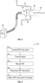
- FIG. 2 is a schematic illustration of an embodiment of an aircraft 44, when in the stowed position the RAT assembly 14 is disposed in a RAT bay 42 of the aircraft 44, which in some embodiments is in a fuselage 46 of the aircraft 44.
- the RAT assembly 14 is operably connected to a retraction mechanism 48, such as a linear or rotary actuator, or the like, which is located in the fuselage 46.
- a RAT stow panel 50 is operably connected to the retraction mechanism 48 to signal the retraction mechanism 48 to retract the RAT assembly 14.
- the RAT stow panel 50 is a stand-alone piece of equipment not built into the aircraft 44, but is kept on the ground such in a maintenance tool storage or the like, and may be shared among several aircraft 44.
- the RAT stow panel 50 is operably connected to the retraction mechanism 48 via a stow connector 52, which includes a panel connector portion 54 which is part of the RAT stow panel 50.
- the aircraft connector 56 is operably connected to the retraction mechanism 48 via a retraction lead 62 which is, for example, an electrical wire connection, a fiber optic connection or a hydraulic connection.
- the aircraft connector 56 is connected to the retraction mechanism 48 to transmit a retraction signal from the RAT stow panel 50 to the retraction mechanism 48 via the retraction lead 62.
- the RAT stow panel 50 includes, in some embodiments, a power source 64, a signal transmitter 66 and a switch 68 contained in a panel housing 70.
- the switch 68 is connected to the power source 64 and the signal transmitter 66 such that when the switch 68 is activated the signal transmitter 66 transmits a stow signal along a panel lead 72 and through the stow connector 52 to the retraction mechanism 48 which then retracts or stows the RAT assembly 14 in the aircraft fuselage 46.
- the RAT stow panel 50 is connected to the retraction mechanism 48 via the aircraft connector 56 portion of the stow connector 52.
- the RAT stow panel 50 is activated by, for example, the switch 68, and a stow signal is transmitted to the retraction mechanism 48.
- the retraction mechanism 48 is activated and retracts the RAT assembly 14 into the stowed position.
- the RAT stow panel 50 is then disconnected from the aircraft connector 56 at step 108, and in some embodiments is returned to maintenance tool storage or similar location at step 110.
- Utilizing the stand-alone RAT stow panel 50 which is not part of the aircraft 44 is advantageous for a number of reasons including the ability to share one or two such devices among several aircraft, thus saving cost of procurement of the RAT stow panels 50. Further, removing the RAT stow panel 50 from the aircraft 44 and storing the device on the ground saves weight on the aircraft 44. Additionally, the RAT stow panel 50 may be simpler and more cost effective since airworthiness of the device is not required, and since the RAT stow panel 50 is not part of an aircraft system, the required design, development and certification effort would be reduced.
Landscapes
- Engineering & Computer Science (AREA)
- Aviation & Aerospace Engineering (AREA)
- Connector Housings Or Holding Contact Members (AREA)
Applications Claiming Priority (1)
| Application Number | Priority Date | Filing Date | Title |
|---|---|---|---|
| IN202311065719 | 2023-09-29 |
Publications (1)
| Publication Number | Publication Date |
|---|---|
| EP4530200A1 true EP4530200A1 (de) | 2025-04-02 |
Family
ID=92895693
Family Applications (1)
| Application Number | Title | Priority Date | Filing Date |
|---|---|---|---|
| EP24202045.1A Pending EP4530200A1 (de) | 2023-09-29 | 2024-09-23 | Stauluftturbinen-staubetätigungssteuerung |
Country Status (2)
| Country | Link |
|---|---|
| US (1) | US20250108933A1 (de) |
| EP (1) | EP4530200A1 (de) |
Citations (3)
| Publication number | Priority date | Publication date | Assignee | Title |
|---|---|---|---|---|
| US20070237640A1 (en) * | 2005-09-07 | 2007-10-11 | Hamilton Sundstrand Corporation | Stow abort mechanism for a ram air turbine |
| EP3284679A1 (de) * | 2016-08-16 | 2018-02-21 | Hamilton Sundstrand Corporation | Verstauung während des fluges einer stauluftturbine |
| EP3865407A1 (de) * | 2020-02-14 | 2021-08-18 | Hamilton Sundstrand Corporation | Handbetätigter hydraulischer kreislauf zum umstauen von stauluftturbinen (rat) |
-
2023
- 2023-11-29 US US18/522,861 patent/US20250108933A1/en not_active Abandoned
-
2024
- 2024-09-23 EP EP24202045.1A patent/EP4530200A1/de active Pending
Patent Citations (3)
| Publication number | Priority date | Publication date | Assignee | Title |
|---|---|---|---|---|
| US20070237640A1 (en) * | 2005-09-07 | 2007-10-11 | Hamilton Sundstrand Corporation | Stow abort mechanism for a ram air turbine |
| EP3284679A1 (de) * | 2016-08-16 | 2018-02-21 | Hamilton Sundstrand Corporation | Verstauung während des fluges einer stauluftturbine |
| EP3865407A1 (de) * | 2020-02-14 | 2021-08-18 | Hamilton Sundstrand Corporation | Handbetätigter hydraulischer kreislauf zum umstauen von stauluftturbinen (rat) |
Non-Patent Citations (1)
| Title |
|---|
| BESING W: "HYDRAULISCHE SYSTEME IN MODERNEN ZIVILEN TRANSPORTFLUGZEUGEN", O & P - OELHYDRAULIK UND PNEUMATIK: ZEITSCHRIFT FUER FLUIDTECHNIK, AKTORIK, STEUERELEKTRONIK UND SENSORIK, VEREINIGTE FACHVERLAGE GMBH, DE, vol. 37, no. 6, 30 June 1993 (1993-06-30), pages 502 - 508, XP000380882, ISSN: 0341-2660 * |
Also Published As
| Publication number | Publication date |
|---|---|
| US20250108933A1 (en) | 2025-04-03 |
Similar Documents
| Publication | Publication Date | Title |
|---|---|---|
| US11952114B2 (en) | Deployable emergency situation awareness support system | |
| EP1370461B1 (de) | Vorrichtung zum starten eines flugzeugs von einem trägerflugzeug | |
| US8827205B2 (en) | Pneumatic blow-down actuator | |
| US6708926B2 (en) | Modular integrated self-contained cargo deployment/retrieval system | |
| US10392103B2 (en) | Detachable power transfer device for a rotary-wing aircraft | |
| US5996939A (en) | Aerial refueling boom with translating pivot | |
| EP1789321B1 (de) | System zum betanken während des fluges, sensorsystem und verfahren zur schwingungsdämpfung für komponenten eines systems zum betanken während des fluges | |
| US4240601A (en) | Method for observing the features characterizing the surface of a land mass | |
| CN106672253A (zh) | 一种无人机收纳箱 | |
| US12252280B2 (en) | Docking station with retractable guide apparatus for unmanned aerial vehicle | |
| GB2577590A (en) | Propellant-handling module for an aircraft | |
| US10513348B2 (en) | Support for a radio equipment of an aircraft, radio system and aircraft | |
| US20250108933A1 (en) | Ram air turbine stow actuation control | |
| EP2527256B1 (de) | Fangtrichterausfahrsystem für Luftbetankung | |
| US20180363495A1 (en) | Emergency wind turbine system comprising a device for rotatably locking the turbine | |
| US4496159A (en) | Aerial gunnery target deployment system | |
| US20150183523A1 (en) | Tail cone driven emergency power generating system | |
| US20170057626A1 (en) | Probe assemblies for aircraft securing systems | |
| EP3088734A1 (de) | Hilfsstromsystem mit doppelter stromquelle für ein flugzeug | |
| EP3700817B1 (de) | Deck-landsystem für flugzeuge | |
| US7422179B2 (en) | Apparatus for aerial refuelling | |
| EP3539868B1 (de) | Flexible kopplung für standrohrbaugruppe | |
| DE102019103592B4 (de) | Notfall-Abschaltmechanismus und Rettungsvorrichtung für ein Fluggerät, damit ausgerüstetes Fluggerät und zugehöriges Betriebsverfahren | |
| CN118062292A (zh) | 无人机的叶片保护装置 | |
| RU2351512C1 (ru) | Возвращаемый автономный космический аппарат с несущим авторотирующим винтом |
Legal Events
| Date | Code | Title | Description |
|---|---|---|---|
| PUAI | Public reference made under article 153(3) epc to a published international application that has entered the european phase |
Free format text: ORIGINAL CODE: 0009012 |
|
| STAA | Information on the status of an ep patent application or granted ep patent |
Free format text: STATUS: THE APPLICATION HAS BEEN PUBLISHED |
|
| AK | Designated contracting states |
Kind code of ref document: A1 Designated state(s): AL AT BE BG CH CY CZ DE DK EE ES FI FR GB GR HR HU IE IS IT LI LT LU LV MC ME MK MT NL NO PL PT RO RS SE SI SK SM TR |
|
| STAA | Information on the status of an ep patent application or granted ep patent |
Free format text: STATUS: REQUEST FOR EXAMINATION WAS MADE |
|
| 17P | Request for examination filed |
Effective date: 20251001 |
|
| GRAP | Despatch of communication of intention to grant a patent |
Free format text: ORIGINAL CODE: EPIDOSNIGR1 |
|
| STAA | Information on the status of an ep patent application or granted ep patent |
Free format text: STATUS: GRANT OF PATENT IS INTENDED |
|
| INTG | Intention to grant announced |
Effective date: 20260217 |
|
| GRAS | Grant fee paid |
Free format text: ORIGINAL CODE: EPIDOSNIGR3 |
|
| GRAA | (expected) grant |
Free format text: ORIGINAL CODE: 0009210 |
|
| STAA | Information on the status of an ep patent application or granted ep patent |
Free format text: STATUS: THE PATENT HAS BEEN GRANTED |