EP4530170A1 - Straddled vehicle - Google Patents
Straddled vehicle Download PDFInfo
- Publication number
- EP4530170A1 EP4530170A1 EP24170499.8A EP24170499A EP4530170A1 EP 4530170 A1 EP4530170 A1 EP 4530170A1 EP 24170499 A EP24170499 A EP 24170499A EP 4530170 A1 EP4530170 A1 EP 4530170A1
- Authority
- EP
- European Patent Office
- Prior art keywords
- acceleration sensor
- vehicle
- center
- acceleration
- gravity
- Prior art date
- Legal status (The legal status is an assumption and is not a legal conclusion. Google has not performed a legal analysis and makes no representation as to the accuracy of the status listed.)
- Granted
Links
Images






Classifications
-
- B—PERFORMING OPERATIONS; TRANSPORTING
- B62—LAND VEHICLES FOR TRAVELLING OTHERWISE THAN ON RAILS
- B62J—CYCLE SADDLES OR SEATS; AUXILIARY DEVICES OR ACCESSORIES SPECIALLY ADAPTED TO CYCLES AND NOT OTHERWISE PROVIDED FOR, e.g. ARTICLE CARRIERS OR CYCLE PROTECTORS
- B62J27/00—Safety equipment
- B62J27/20—Airbags specially adapted for motorcycles or the like
-
- B—PERFORMING OPERATIONS; TRANSPORTING
- B62—LAND VEHICLES FOR TRAVELLING OTHERWISE THAN ON RAILS
- B62J—CYCLE SADDLES OR SEATS; AUXILIARY DEVICES OR ACCESSORIES SPECIALLY ADAPTED TO CYCLES AND NOT OTHERWISE PROVIDED FOR, e.g. ARTICLE CARRIERS OR CYCLE PROTECTORS
- B62J45/00—Electrical equipment arrangements specially adapted for use as accessories on cycles, not otherwise provided for
- B62J45/40—Sensor arrangements; Mounting thereof
- B62J45/41—Sensor arrangements; Mounting thereof characterised by the type of sensor
- B62J45/414—Acceleration sensors
-
- B—PERFORMING OPERATIONS; TRANSPORTING
- B62—LAND VEHICLES FOR TRAVELLING OTHERWISE THAN ON RAILS
- B62K—CYCLES; CYCLE FRAMES; CYCLE STEERING DEVICES; RIDER-OPERATED TERMINAL CONTROLS SPECIALLY ADAPTED FOR CYCLES; CYCLE AXLE SUSPENSIONS; CYCLE SIDECARS, FORECARS, OR THE LIKE
- B62K5/00—Cycles with handlebars, equipped with three or more main road wheels
- B62K5/02—Tricycles
- B62K5/027—Motorcycles with three wheels
-
- B—PERFORMING OPERATIONS; TRANSPORTING
- B62—LAND VEHICLES FOR TRAVELLING OTHERWISE THAN ON RAILS
- B62K—CYCLES; CYCLE FRAMES; CYCLE STEERING DEVICES; RIDER-OPERATED TERMINAL CONTROLS SPECIALLY ADAPTED FOR CYCLES; CYCLE AXLE SUSPENSIONS; CYCLE SIDECARS, FORECARS, OR THE LIKE
- B62K5/00—Cycles with handlebars, equipped with three or more main road wheels
- B62K5/02—Tricycles
- B62K5/05—Tricycles characterised by a single rear wheel
Definitions
- Straddled vehicles that riders straddle to ride are known in the art.
- Examples of such straddled vehicles known in the art include: a motorcycle including a front wheel and a rear wheel (see, for example, JP 2011-117339 A ); and a leaning vehicle including two front wheels and a rear wheel (see, for example, JP 2017-171275 A ).
- a straddled vehicle disclosed herein includes: a body frame including a head pipe; a front wheel supported by the body frame; a rear wheel supported by the body frame; a seat disposed behind the head pipe and supported by the body frame; a first acceleration sensor to detect an acceleration; and an airbag that expands in accordance with the acceleration detected by the first acceleration sensor.
- the airbag When the straddled vehicle undergoes a high acceleration owing to a frontal collision, the airbag expands in accordance with the acceleration detected by the first acceleration sensor. Because the airbag absorbs an impact resulting from the frontal collision, this arrangement is expected to enhance safety of the straddled vehicle.
- this arrangement makes it possible to prevent the vehicle component(s) from interfering with the first acceleration sensor and/or the second acceleration sensor. Accordingly, this arrangement is able to increase the flexibility of location(s) of the vehicle component(s).
- this arrangement makes it possible to relatively accurately detect a collision acceleration in accordance with detection results obtained by the first acceleration sensor and the second acceleration sensor.
- the motorcycle 1 includes a seat 2 on which a rider sits.
- the following description is based on the assumption that unless otherwise specified, the terms “front”, “rear”, “left”, “right”, “up”, and “down” respectively refer to front, rear, left, right, up, and down with respect to a virtual rider sitting on the seat 2 when the motorcycle 1 with no rider or luggage thereon is stationary in an upright position on a horizontal plane.
- the reference signs “F”, “Rr”, “L”, “R”, “U”, and “D” in the drawings respectively represent front, rear, left, right, up, and down.
- the term “center of gravity of the motorcycle 1” refers to a center of gravity of the motorcycle 1 when the motorcycle 1 with no rider or luggage thereon is stationary in an upright position on a horizontal plane.
- the motorcycle 1 includes a body frame 5 including a head pipe 5A.
- a steering shaft (not illustrated) is inserted into the head pipe 5A.
- the steering shaft is supported by the head pipe 5A so as to be rotatable rightward and leftward.
- An upper portion of the steering shaft has a handlebar 6 secured thereto.
- a lower portion of the steering shaft has a front fork 7 secured thereto.
- the front wheel 3 is rotatably supported by the front fork 7.
- the front wheel 3 is indirectly supported by the body frame 5 through the front fork 7 and/or other component(s).
- the first acceleration sensor 31 is disposed forward of the center of gravity CG
- the second acceleration sensor 32 is disposed rearward of the center of gravity CG.
- the yawing-induced right-left acceleration A1 detected by the first acceleration sensor 31 is a rightward acceleration
- the yawing-induced right-left acceleration A2 detected by the second acceleration sensor 32 is a leftward acceleration.
- a difference between the right-left acceleration detected by the first acceleration sensor 31 and the right-left acceleration detected by the second acceleration sensor 32 increases by a difference between the yawing-induced accelerations A1 and A2. Accordingly, the difference between the right-left acceleration detected by the first acceleration sensor 31 and the right-left acceleration detected by the second acceleration sensor 32 is relatively great.
- the center of gravity CG is located at the midpoint of an imaginary line connecting the first acceleration sensor 31 with the second acceleration sensor 32 in the plan view of the motorcycle 1 (see FIG. 6(b) ).
- A3 A4
- the present embodiment is able to accurately detect the collision acceleration AG in accordance with detection results obtained by the first acceleration sensor 31 and the second acceleration sensor 32.
- a collision of the motorcycle 1 with another vehicle, a wall, or any other collision object located in front of or forward of the motorcycle 1 lifts a rear portion of the motorcycle 1, resulting in pitching of the motorcycle 1 around the center of gravity CG.
- an acceleration detected by the acceleration sensor 35 is the sum of an acceleration AG indicating the magnitude of a collision (i.e., a collision acceleration) and a pitching-induced front-rear acceleration A5.
- the acceleration detected by the acceleration sensor 35 is deviated from the collision acceleration AG by the pitching-induced front-rear acceleration A5.
- the body frame 5 includes a head pipe 5A and a main frame 53 extending rearward from the head pipe 5A. As illustrated in FIG. 12 , the body frame 5 further includes: a left side member 52L disposed to the left of the head pipe 5A; and a right side member 52R disposed to the right of the head pipe 5A.
- the left side member 52L and the right side member 52R are each in the form of a pipe and disposed in parallel or substantially in parallel with the head pipe 5A.
- the link mechanism 51 connects the head pipe 5A, the left side member 52L, and the right side member 52R to each other.
- the link mechanism 51 is configured to incline the left side member 52L and the right side member 52R in accordance with an inclination of the head pipe 5A (see FIG. 14 ).
- the link mechanism 51 includes a first cross member 61 and a second cross member 62 each extending in a vehicle right-left direction.
- the tie rod 57 synchronizes rotation of the steering shaft 54 around a central steering axis V2C, rotation of the left front wheel support member 56L around the left steering axis V2L, and rotation of the right front wheel support member 56R around a right steering axis V2R.
- the tie rod 57 is connected to the steering shaft 54, the left front wheel support member 56L, and the right front wheel support member 56R such that the tie rod 57 is rotatable around axes V1 each extending in the vehicle up-down direction.
- the leaning vehicle 1A includes an airbag device 20.
- the airbag device 20 includes an airbag 21 and an inflator 22 (see FIG. 1 ) similarly to the first embodiment.
- the center of gravity CG of the leaning vehicle 1A would be highly likely to be located inside the triangle 70.
- the first acceleration sensor 31 and the second acceleration sensor 32 are disposed inside the triangle 70 in the plan view as previously mentioned. Accordingly, if the center of gravity CG shifts forward on the leaning vehicle 1A at the time of a collision, accelerations at the time of the collision would be detected at locations close to the center of gravity CG, and thus the influence of disturbances would be reduced. Consequently, the present embodiment is able to successfully detect collision-induced accelerations.
- the first acceleration sensor 31 is disposed forward of the center of gravity CG and the second acceleration sensor 32 is disposed rearward of the center of gravity CG similarly to the first embodiment.
- the present embodiment is able to determine whether an impact force has applied to the center of gravity CG or to a location deviated from the center of gravity CG in a vehicle front-rear direction of the leaning vehicle 1A in accordance with detection results obtained by the first acceleration sensor 31 and the second acceleration sensor 32.
- the first acceleration sensor 31 and the second acceleration sensor 32 are disposed above the center of gravity CG similarly to the first embodiment. Accordingly, the present embodiment is able to prevent relatively large vehicle components disposed below the center of gravity CG from interfering with the first acceleration sensor 31 and the second acceleration sensor 32. Consequently, the present embodiment is able to increase the flexibility of locations of the vehicle components.
- the first acceleration sensor 31 is disposed rightward of the center of gravity CG and the second acceleration sensor 32 is disposed leftward of the center of gravity CG similarly to the first embodiment.
- the present embodiment would be able to relatively accurately detect a collision acceleration in accordance with detection results obtained by the first acceleration sensor 31 and the second acceleration sensor 32.
- a leaning vehicle 1A according to a fourth embodiment according to the present teaching differs from the leaning vehicle 1A according to the third embodiment in the positions of a first acceleration sensor 31 and a second acceleration sensor 32. Because the fourth embodiment is similar to the third embodiment except for the positions of the first acceleration sensor 31 and the second acceleration sensor 32, overlapping description will not be given.
- the first acceleration sensor 31 is disposed forward of a center of gravity CG of the leaning vehicle 1A
- the second acceleration sensor 32 is disposed rearward of the center of gravity CG of the leaning vehicle 1A.
- the first acceleration sensor 31 is disposed rightward of the center of gravity CG of the leaning vehicle 1A
- the second acceleration sensor 32 is disposed leftward of the center of gravity CG of the leaning vehicle 1A.
- the first acceleration sensor 31 and the second acceleration sensor 32 are disposed below the center of gravity CG of the leaning vehicle 1A.
- the first acceleration sensor 31 is disposed inside a virtual triangle 70 whose apexes are defined by a center 3Lc of a left front wheel 3L, a center 3Rc of a right front wheel 3R, and a center 4c of a rear wheel 4 in a plan view of the leaning vehicle 1A.
- the first acceleration sensor 31 and the second acceleration sensor 32 are disposed below the center of gravity CG similarly to the second embodiment.
- the first acceleration sensor 31 and the second acceleration sensor 32 are located close to the center of rotation of pitching in an vehicle up-down direction from an early stage of the collision similarly to the second embodiment. Accordingly, the present embodiment is able to relatively correctly detect a collision acceleration with the first acceleration sensor 31 and the second acceleration sensor 32.
- the first acceleration sensor 31 and the second acceleration sensor 32 are disposed above rotation centers 3c (see FIG. 16 ) of the left front wheel 3L and the right front wheel 3R and below the center of gravity CG.
- the first acceleration sensor 31 and the second acceleration sensor 32 are thus located close to the center of rotation of pitching in the vehicle up-down direction from an early stage to a final stage of a collision. Consequently, the present embodiment is able to relatively accurately detect a collision acceleration.
- the first acceleration sensor 31 is disposed rearward of the rotation centers 3c of the left front wheel 3L and the right front wheel 3R and forward of the center of gravity CG. With the first acceleration sensor 31, the present embodiment is able to more accurately detect a collision acceleration from an early stage to a final stage of a collision.
- the first acceleration sensor 31 is disposed forward of the center of gravity CG and the second acceleration sensor 32 is disposed rearward of the center of gravity CG similarly to the first embodiment.
- the present embodiment is able to determine whether an impact force has applied to the center of gravity CG or to a location deviated from the center of gravity CG in a vehicle front-rear direction of the leaning vehicle 1A in accordance with detection results obtained by the first acceleration sensor 31 and the second acceleration sensor 32.
- the first acceleration sensor 31 is disposed rightward of the center of gravity CG and the second acceleration sensor 32 is disposed leftward of the center of gravity CG similarly to the first embodiment.
- the present embodiment would be able to relatively accurately detect a collision acceleration in accordance with detection results obtained by the first acceleration sensor 31 and the second acceleration sensor 32.
- the first acceleration sensor 31 is disposed inside the triangle 70 in the plan view similarly to the third embodiment. Accordingly, if the center of gravity CG shifts forward on the leaning vehicle 1A at the time of a collision, an acceleration at the time of the collision would be detected at a location close to the center of gravity CG by the first acceleration sensor 31, and thus the influence of disturbances would be reduced. Consequently, with the first acceleration sensor 31, the present embodiment is able to successfully detect a collision-induced acceleration.
- the second acceleration sensor 32 is located outside the triangle 70 in the plan view. Alternatively, the second acceleration sensor 32 may be disposed inside the triangle 70 in the plan view similarly to the third embodiment. In this case, the fourth embodiment is able to achieve effects similar to those achieved by the third embodiment.
- the first acceleration sensor 31 may be disposed forward and leftward of the center of gravity CG, and/or the second acceleration sensor 32 may be disposed rearward and rightward of the center of gravity CG. In the variation of the first to the fourth embodiments, the positions of the first acceleration sensor 31 and the second acceleration sensor 32 may be reversed.
- the driving source for travel of the straddled vehicle according to each of the foregoing embodiments is not limited to the engine 8.
- the driving source for travel of the straddled vehicle according to each of the foregoing embodiments may be an electric motor.
- the term “straddled vehicle” refers to a vehicle that a rider straddles to ride.
- the term “straddled vehicle” used herein is not limited to a motorcycle.
- the term “straddled vehicle” used herein is not limited to a motor tricycle including two front wheels and a rear wheel.
- the straddled vehicle according to each of the foregoing embodiments is configured such that its body frame inclines relative to the ground when the straddled vehicle makes a turn.
- the straddled vehicle according to each of the foregoing embodiments does not necessarily have to be configured such that its body frame inclines.
- the straddled vehicle according to each of the foregoing embodiments may be, for example, an all-terrain vehicle (ATV).
- ATV all-terrain vehicle
Landscapes
- Engineering & Computer Science (AREA)
- Mechanical Engineering (AREA)
- Automatic Cycles, And Cycles In General (AREA)
Abstract
Description
- The present invention relates to a straddled vehicle.
- Straddled vehicles that riders straddle to ride are known in the art. Examples of such straddled vehicles known in the art include: a motorcycle including a front wheel and a rear wheel (see, for example,
JP 2011-117339 A JP 2017-171275 A - It is the object of the present invention to provide a straddled vehicle being able to absorb and/or reduce kinetic energy when a rider is separated from the vehicle upon frontal collision so as to reduce an impact on the rider. According to the present invention said object is solved by a straddled vehicle having the features of
independent claim 1. Preferred embodiments are laid down in the dependent claims. - A straddled vehicle disclosed herein includes: a body frame including a head pipe; a front wheel supported by the body frame; a rear wheel supported by the body frame; a seat disposed behind the head pipe and supported by the body frame; a first acceleration sensor to detect an acceleration; and an airbag that expands in accordance with the acceleration detected by the first acceleration sensor.
- When the straddled vehicle undergoes a high acceleration owing to a frontal collision, the airbag expands in accordance with the acceleration detected by the first acceleration sensor. Because the airbag absorbs an impact resulting from the frontal collision, this arrangement is expected to enhance safety of the straddled vehicle.
- The straddled vehicle may further include a second acceleration sensor to detect an acceleration. One of the first acceleration sensor and the second acceleration sensor may be disposed forward of a center of gravity of the straddled vehicle. The other one of the first acceleration sensor and the second acceleration sensor may be disposed rearward of the center of gravity of the straddled vehicle.
- When an impact force has applied laterally to the straddled vehicle, this arrangement makes it possible to relatively easily determine whether the impact force has applied to the center of gravity or to a location deviated from the center of gravity. Accordingly, this arrangement makes it possible to grasp a situation at the time of an accident.
- The first acceleration sensor and/or the second acceleration sensor may be disposed above the center of gravity of the straddled vehicle.
- When relatively large vehicle component(s) is/are disposed below the center of gravity, this arrangement makes it possible to prevent the vehicle component(s) from interfering with the first acceleration sensor and/or the second acceleration sensor. Accordingly, this arrangement is able to increase the flexibility of location(s) of the vehicle component(s).
- One of the first acceleration sensor and the second acceleration sensor may be disposed leftward of the center of gravity of the straddled vehicle. The other one of the first acceleration sensor and the second acceleration sensor may be disposed rightward of the center of gravity of the straddled vehicle.
- When the straddled vehicle yaws at the time of a collision, this arrangement makes it possible to relatively accurately detect a collision acceleration in accordance with detection results obtained by the first acceleration sensor and the second acceleration sensor.
- The first acceleration sensor and/or the second acceleration sensor may be disposed below the center of gravity of the straddled vehicle.
- This arrangement makes it possible to more accurately detect a collision acceleration from an early stage to a final stage of a collision.
- The front wheel may be a left front wheel disposed leftward of the head pipe. The straddled vehicle may further include a right front wheel disposed rightward of the head pipe. The rear wheel may be disposed on a vehicle central line in a plan view of the straddled vehicle. The first acceleration sensor and/or the second acceleration sensor may be disposed inside a virtual triangle whose apexes are defined by a center of the left front wheel, a center of the right front wheel, and a center of the rear wheel in the plan view of the straddled vehicle.
- Accordingly, if the center of gravity shifts forward on the straddled vehicle at the time of a collision, acceleration(s) at the time of the collision would be detected at location(s) close to the center of gravity, and thus the influence of disturbances would be reduced. Consequently, this arrangement makes it possible to successfully detect collision-induced acceleration(s).
- Various embodiments of the present invention are expected to enhance security of straddled vehicles against frontal collisions.
-
-
FIG. 1 is a left side view of a motorcycle according to a first embodiment according to the present teaching. -
FIG. 2 is a font view of the motorcycle according to the first embodiment. -
FIG. 3 is a plan view of the motorcycle according to the first embodiment. -
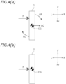
FIGS. 4(a) and 4(b) are diagrams each schematically illustrating an impact force applied laterally to the motorcycle. -
FIGS. 5(a) and 5(b) are diagrams each illustrating yawing-induced right-left accelerations detected by a first acceleration sensor and a second acceleration sensor. -
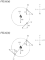
FIGS. 6(a) and 6(b) are diagrams each illustrating yawing-induced front-rear accelerations detected by the first acceleration sensor and the second acceleration sensor. -
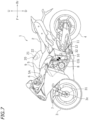
FIG. 7 is a left side view of a motorcycle according to a second embodiment according to the present teaching. -
FIG. 8 is a front view of the motorcycle according to the second embodiment. -
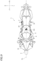
FIG. 9 is a plan view of the motorcycle according to the second embodiment. -
FIG. 10 is a diagram illustrating pitching-induced front-rear accelerations detected by an acceleration sensor disposed above a center of gravity and another acceleration sensor disposed at the same height as the center of gravity. -
FIG. 11 is a left side view of main components of a leaning vehicle according to a third embodiment according to the present teaching. -
FIG. 12 is a front view of the main components of the leaning vehicle according to the third embodiment. -
FIG. 13 is a plan view of the main components of the leaning vehicle according to the third embodiment. -
FIG. 14 is a front view of the leaning vehicle according to the third embodiment when the leaning vehicle is inclined leftward. -
FIG. 15 is a left side view of main components of a leaning vehicle according to a fourth embodiment according to the present teaching. -
FIG. 16 is a front view of the main components of the leaning vehicle according to the fourth embodiment. -
FIG. 17 is a plan view of the main components of the leaning vehicle according to the fourth embodiment. - Embodiments of straddled vehicles according to the present teaching will be described below with reference to the drawings.
- As illustrated in
FIG. 1 , a straddled vehicle according to a first embodiment according to the present teaching is amotorcycle 1 including afront wheel 3 and arear wheel 4.FIG. 1 is a left side view of themotorcycle 1.FIG. 2 is a front view of themotorcycle 1.FIG. 3 is a plan view of themotorcycle 1. - The
motorcycle 1 includes aseat 2 on which a rider sits. The following description is based on the assumption that unless otherwise specified, the terms "front", "rear", "left", "right", "up", and "down" respectively refer to front, rear, left, right, up, and down with respect to a virtual rider sitting on theseat 2 when themotorcycle 1 with no rider or luggage thereon is stationary in an upright position on a horizontal plane. The reference signs "F", "Rr", "L", "R", "U", and "D" in the drawings respectively represent front, rear, left, right, up, and down. Unless otherwise specified, the term "center of gravity of themotorcycle 1" refers to a center of gravity of themotorcycle 1 when themotorcycle 1 with no rider or luggage thereon is stationary in an upright position on a horizontal plane. - As illustrated in
FIG. 1 , themotorcycle 1 includes abody frame 5 including ahead pipe 5A. A steering shaft (not illustrated) is inserted into thehead pipe 5A. The steering shaft is supported by thehead pipe 5A so as to be rotatable rightward and leftward. An upper portion of the steering shaft has ahandlebar 6 secured thereto. A lower portion of the steering shaft has afront fork 7 secured thereto. Thefront wheel 3 is rotatably supported by thefront fork 7. Thefront wheel 3 is indirectly supported by thebody frame 5 through thefront fork 7 and/or other component(s). - The
body frame 5 supports an internal combustion engine 8 (hereinafter referred to as an "engine 8") serving as a driving source for travel of themotorcycle 1. Afuel tank 9 is disposed behind thehead pipe 5A and in front of theseat 2. Theseat 2 and thefuel tank 9 are supported by thebody frame 5. - The
body frame 5 is connected with arear arm 11 through apivot shaft 10. Therear arm 11 is swingable relative to thebody frame 5 around thepivot shaft 10. Therear wheel 4 is rotatably supported by a rear end portion of therear arm 11. Therear wheel 4 is indirectly supported by thebody frame 5 through therear arm 11. Theengine 8 and therear wheel 4 are connected to each other through achain 12 such that power is transmittable between theengine 8 and therear wheel 4. Thechain 12 is a power transmission member through which power generated by theengine 8 is transmitted to therear wheel 4. The power transmission member, however, is not limited to thechain 12. The power transmission member may be a transmission belt, a drive shaft, or any other suitable power transmission member. - The
motorcycle 1 includes anairbag device 20. Theairbag device 20 is disposed in front of theseat 2. Theairbag device 20, however, may be located at an any other suitable position. Theairbag device 20 includes anairbag 21 and an inflator 22 to generate inflation gas to be supplied to theairbag 21. Upon supply of the inflation gas to theairbag 21, theairbag 21 inflates outward. Outward inflation of theairbag 21 will hereinafter be referred to as "expansion of theairbag 21". - Upon receiving an impact resulting from a frontal collision, the
motorcycle 1 undergoes a high acceleration. When themotorcycle 1 undergoes a high acceleration, theinflator 22 generates inflation gas, which expands theairbag 21. Themotorcycle 1 includes afirst acceleration sensor 31 and asecond acceleration sensor 32 to detect accelerations. Theairbag device 20 is configured to expand theairbag 21 in accordance with acceleration(s) detected by thefirst acceleration sensor 31 and/or thesecond acceleration sensor 32. In consideration of, for example, a driving condition, theairbag device 20 expands theairbag 21 when the acceleration(s) detected by thefirst acceleration sensor 31 and/or thesecond acceleration sensor 32 is/are equal to or greater than a predetermined threshold value. Thefirst acceleration sensor 31 and thesecond acceleration sensor 32 may be directly secured to thebody frame 5 or may be indirectly secured to thebody frame 5 through other member(s). - As illustrated in
FIGS. 1 and3 , thefirst acceleration sensor 31 is disposed forward of a center of gravity CG of themotorcycle 1, and thesecond acceleration sensor 32 is disposed rearward of the center of gravity CG of themotorcycle 1. As illustrated inFIGS. 2 and3 , thefirst acceleration sensor 31 is disposed rightward of the center of gravity CG of themotorcycle 1, and thesecond acceleration sensor 32 is disposed leftward of the center of gravity CG of themotorcycle 1. As illustrated inFIGS. 1 and2 , thefirst acceleration sensor 31 and thesecond acceleration sensor 32 are disposed above the center of gravity CG of themotorcycle 1. - The
motorcycle 1 includes acontroller 40 communicably connected to thefirst acceleration sensor 31, thesecond acceleration sensor 32, and theinflator 22 of theairbag device 20. Thecontroller 40 includes a microcomputer. Thecontroller 40 activates the inflator 22 in accordance with detection result(s) obtained by thefirst acceleration sensor 31 and/or thesecond acceleration sensor 32. Thecontroller 40 causes theairbag 21 to expand, for example, when an acceleration detected by thefirst acceleration sensor 31 or an acceleration detected by thesecond acceleration sensor 32 is equal to or greater than a threshold value. Themotorcycle 1 may include a memory to store detection results obtained by thefirst acceleration sensor 31 and thesecond acceleration sensor 32. The memory may be separate from thecontroller 40. Thecontroller 40 may also function as the memory. - To correctly detect and record right-left accelerations of the
motorcycle 1 at the time of a collision is important in grasping a situation at the time of an accident. Another vehicle may collide with themotorcycle 1 from the left or the right. Themotorcycle 1 may obliquely collide with another vehicle, a wall, or any other collision object. For example, when a rightward impact force F is applied to a portion of themotorcycle 1 deviated from the center of gravity CG as illustrated inFIG. 4(a) , yawing of themotorcycle 1 around the center of gravity CG occurs. In this case, themotorcycle 1 undergoes a rightward acceleration AC, a portion of themotorcycle 1 located forward of the center of gravity CG undergoes a yawing-induced rightward acceleration AR, and a portion of themotorcycle 1 located rearward of the center of gravity CG undergoes a yawing-induced leftward acceleration AL. When the rightward impact force F is applied to the center of gravity CG as illustrated inFIG. 4(b) , themotorcycle 1 undergoes the rightward acceleration AC, but themotorcycle 1 undergoes no yawing-induced acceleration AR or AL. - Suppose that both of the
first acceleration sensor 31 and thesecond acceleration sensor 32 are disposed forward of the center of gravity CG as illustrated inFIG. 5(a) . In this case, when the yawing of themotorcycle 1 has occurred, a yawing-induced right-left acceleration A1 detected by thefirst acceleration sensor 31 and a yawing-induced right-left acceleration A2 detected by thesecond acceleration sensor 32 are both rightward accelerations. Accordingly, if a comparison is made between detection results obtained by thefirst acceleration sensor 31 and thesecond acceleration sensor 32, whether an impact fore has applied to the center of gravity CG or to a location deviated from the center of gravity CG is difficult to determine. - In the present embodiment, however, the
first acceleration sensor 31 is disposed forward of the center of gravity CG, and thesecond acceleration sensor 32 is disposed rearward of the center of gravity CG. As illustrated inFIG. 5(b) , when the yawing of themotorcycle 1 has occurred, the yawing-induced right-left acceleration A1 detected by thefirst acceleration sensor 31 is a rightward acceleration, and the yawing-induced right-left acceleration A2 detected by thesecond acceleration sensor 32 is a leftward acceleration. A difference between the right-left acceleration detected by thefirst acceleration sensor 31 and the right-left acceleration detected by thesecond acceleration sensor 32 increases by a difference between the yawing-induced accelerations A1 and A2. Accordingly, the difference between the right-left acceleration detected by thefirst acceleration sensor 31 and the right-left acceleration detected by thesecond acceleration sensor 32 is relatively great. - For example, assuming that an average right-left acceleration the
motorcycle 1 undergoes is represented by A0, the right-left acceleration detected by thefirst acceleration sensor 31 is A0 + A1, and the right-left acceleration detected by thesecond acceleration sensor 32 is A0 - A2. The difference between the right-left acceleration detected by thefirst acceleration sensor 31 and the right-left acceleration detected by thesecond acceleration sensor 32 is calculated by the following expression: (A0 + A1) - (A0 - A2) = A1 + A2. When the yawing of themotorcycle 1 does not occur, the difference between the right-left acceleration detected by thefirst acceleration sensor 31 and the right-left acceleration detected by thesecond acceleration sensor 32 is zero or a relatively small value. In the present embodiment, in particular, the center of gravity CG is located at the midpoint of an imaginary line connecting thefirst acceleration sensor 31 with thesecond acceleration sensor 32 in a plan view of the motorcycle 1 (seeFIG. 5(b) ). Consequently, the present embodiment makes it possible to accurately grasp a situation at the time of an accident. - A portion of the
engine 8 of themotorcycle 1 according to the present embodiment is disposed below the center of gravity CG (seeFIG. 1 ). Depending on the type of a motorcycle (e.g., in the case of a scooter), not only an engine but also a fuel tank, an air cleaner, and/or other component(s) may be disposed below the center of gravity. Thus, in some motorcycles, relatively large vehicle components may be disposed below the center of gravity. Disposing thefirst acceleration sensor 31 and thesecond acceleration sensor 32 above the center of gravity CG as in the present embodiment makes it possible to prevent relatively large vehicle components disposed below the center of gravity CG from interfering with thefirst acceleration sensor 31 and thesecond acceleration sensor 32. Accordingly, the present embodiment is able to increase the flexibility of locations of the vehicle components. - As previously described, an oblique collision of the
motorcycle 1 with another vehicle, a wall, or any other collision object results in yawing of themotorcycle 1 around the center of gravity CG. In this case, thefirst acceleration sensor 31 and thesecond acceleration sensor 32 each undergo not only a rearward acceleration indicating the magnitude of the collision but also a yawing-induced acceleration. - Suppose that both of the
first acceleration sensor 31 and thesecond acceleration sensor 32 are disposed rightward or leftward of the center of gravity CG as illustrated inFIG. 6(a) . In this case, when the yawing of themotorcycle 1 has occurred, a yawing-induced front-rear acceleration A3 detected by thefirst acceleration sensor 31 and a yawing-induced front-rear acceleration A4 detected by thesecond acceleration sensor 32 are both rearward accelerations. A front-rear acceleration detected by thefirst acceleration sensor 31 is the sum of an acceleration AG indicating the magnitude of a collision (which will hereinafter be referred to as a "collision acceleration AG") and the yawing-induced front-rear acceleration A3. A front-rear acceleration detected by thesecond acceleration sensor 32 is the sum of the collision acceleration AG and the yawing-induced front-rear acceleration A4. The acceleration detected by the first acceleration sensor 31 (which is represented as AG + A3) and the acceleration detected by the second acceleration sensor 32 (which is represented as AG + A4) are both values deviated from the collision acceleration AG. Thus, when both of thefirst acceleration sensor 31 and thesecond acceleration sensor 32 are disposed rightward or leftward of the center of gravity CG, occurrence of yawing makes it difficult to accurately detect the collision acceleration AG. - In the present embodiment, however, the
first acceleration sensor 31 is disposed rightward of the center of gravity CG, and thesecond acceleration sensor 32 is disposed leftward of the center of gravity CG. As illustrated inFIG. 6(b) , when the yawing of themotorcycle 1 has occurred, the yawing-induced front-rear acceleration A3 detected by thefirst acceleration sensor 31 is a rearward acceleration, and the yawing-induced front-rear acceleration A4 detected by thesecond acceleration sensor 32 is a forward acceleration. The acceleration detected by thefirst acceleration sensor 31 is AG + A3, and the acceleration detected by thesecond acceleration sensor 32 is AG - A4. Accordingly, the present embodiment involves calculating the average of the acceleration detected by thefirst acceleration sensor 31 and the acceleration detected by the second acceleration sensor 32 (which will hereinafter be referred to as an "average acceleration"), so that a portion or an entirety of the yawing-induced front-rear acceleration A3 detected by thefirst acceleration sensor 31 is cancelled out with the yawing-induced front-rear acceleration A4 detected by thesecond acceleration sensor 32. Specifically, the average acceleration is calculated as follows: [(AG + A3) + (AG - A4)]/2 = AG + (A3 - A4)/2. The average acceleration thus calculated is relatively close to the collision acceleration AG. Consequently, the present embodiment is able to relatively accurately detect the collision acceleration AG in accordance with detection results obtained by thefirst acceleration sensor 31 and thesecond acceleration sensor 32. - In the present embodiment, the center of gravity CG is located at the midpoint of an imaginary line connecting the
first acceleration sensor 31 with thesecond acceleration sensor 32 in the plan view of the motorcycle 1 (seeFIG. 6(b) ). Thus, A3 = A4, with the result that the average acceleration is equal to the collision acceleration AG. Consequently, the present embodiment is able to accurately detect the collision acceleration AG in accordance with detection results obtained by thefirst acceleration sensor 31 and thesecond acceleration sensor 32. - As illustrated in
FIGS. 7 to 9 , themotorcycle 1 according to a second embodiment according to the present teaching differs from themotorcycle 1 according to the first embodiment in the positions of afirst acceleration sensor 31 and asecond acceleration sensor 32. Because the second embodiment is similar to the first embodiment except for the positions of thefirst acceleration sensor 31 and thesecond acceleration sensor 32, overlapping description will not be given. - As illustrated in
FIGS. 7 and9 , thefirst acceleration sensor 31 is disposed forward of a center of gravity CG of themotorcycle 1, and thesecond acceleration sensor 32 is disposed rearward of the center of gravity CG of themotorcycle 1. As illustrated inFIGS. 8 and9 , thefirst acceleration sensor 31 is disposed rightward of the center of gravity CG of themotorcycle 1, and thesecond acceleration sensor 32 is disposed leftward of the center of gravity CG of themotorcycle 1. As illustrated inFIGS. 7 and8 , thefirst acceleration sensor 31 and thesecond acceleration sensor 32 are disposed below the center of gravity CG of themotorcycle 1. - A collision of the
motorcycle 1 with another vehicle, a wall, or any other collision object located in front of or forward of themotorcycle 1 lifts a rear portion of themotorcycle 1, resulting in pitching of themotorcycle 1 around the center of gravity CG. As illustrated inFIG. 10 , when anacceleration sensor 35 is disposed above the center of gravity CG, an acceleration detected by theacceleration sensor 35 is the sum of an acceleration AG indicating the magnitude of a collision (i.e., a collision acceleration) and a pitching-induced front-rear acceleration A5. The acceleration detected by theacceleration sensor 35 is deviated from the collision acceleration AG by the pitching-induced front-rear acceleration A5. When anacceleration sensor 36 is disposed at the same height as the center of gravity CG, a pitching-induced front-rear acceleration detected by theacceleration sensor 36 is zero. The acceleration detected by theacceleration sensor 36 thus corresponds to the collision acceleration AG. Accordingly, theacceleration sensor 36 thus disposed is able to correctly detect the collision acceleration AG. - At an early stage of a collision, however, not the center of gravity CG but a
center 3c (seeFIG. 7 ) of afront wheel 3 actually functions as the center of rotation of pitching owing to contact of thefront wheel 3 with a collision object. After the early stage of the collision, the center of pitching shifts from thecenter 3c of thefront wheel 3 to the center of gravity CG. In the present embodiment, thefirst acceleration sensor 31 and thesecond acceleration sensor 32 are disposed below the center of gravity CG. Thus, when pitching has occurred owing to a collision, thefirst acceleration sensor 31 and thesecond acceleration sensor 32 are located close to the center of rotation of pitching in an vehicle up-down direction from an early stage of the collision. Accordingly, the present embodiment is able to relatively correctly detect the collision acceleration with thefirst acceleration sensor 31 and thesecond acceleration sensor 32. In the present embodiment, in particular, thefirst acceleration sensor 31 and thesecond acceleration sensor 32 are disposed above thecenter 3c of thefront wheel 3 and below the center of gravity CG. Thefirst acceleration sensor 31 and thesecond acceleration sensor 32 are thus located close to the center of rotation of pitching in the vehicle up-down direction from an early stage to a final stage of a collision. Consequently, the present embodiment is able to relatively accurately detect the collision acceleration. In the present embodiment, thefirst acceleration sensor 31 is disposed rearward of thecenter 3c of thefront wheel 3 and forward of the center of gravity CG. With thefirst acceleration sensor 31, the present embodiment is able to more accurately detect the collision acceleration from an early stage to a final stage of a collision. - In the present embodiment, the
first acceleration sensor 31 is disposed forward of the center of gravity CG and thesecond acceleration sensor 32 is disposed rearward of the center of gravity CG similarly to the first embodiment. Thus, similarly to the first embodiment, the present embodiment is able to determine whether an impact force has applied to the center of gravity CG or to a location deviated from the center of gravity CG in a vehicle front-rear direction of themotorcycle 1 in accordance with detection results obtained by thefirst acceleration sensor 31 and thesecond acceleration sensor 32. - In the present embodiment, the
first acceleration sensor 31 is disposed rightward of the center of gravity CG and thesecond acceleration sensor 32 is disposed leftward of the center of gravity CG similarly to the first embodiment. Thus, if yawing has occurred owing to a collision, the present embodiment would be able to relatively accurately detect the collision acceleration in accordance with detection results obtained by thefirst acceleration sensor 31 and thesecond acceleration sensor 32. - As illustrated in
FIGS. 11 to 13 , a straddled vehicle according to a third embodiment according to the present teaching is a leaningvehicle 1A including two front wheels (i.e., aleft front wheel 3L and aright front wheel 3R) and arear wheel 4. The leaningvehicle 1A is a motor tricycle.FIG. 11 is a left side view of main components of the leaningvehicle 1A.FIG. 12 is a front view of the main components of the leaningvehicle 1A.FIG. 13 is a plan view of the main components of the leaningvehicle 1A. The leaningvehicle 1A inclines rightward in making a right turn and inclines leftward in making a left turn (seeFIG. 14 ). In the following description, components similar to or corresponding to those in the first embodiment are identified by the same reference signs. - As illustrated in
FIG. 11 , the leaningvehicle 1A includes aseat 2 on which arider 100 sits. The following description is based on the assumption that unless otherwise specified, the terms "front", "rear", "left", "right", "up", and "down" respectively refer to front, rear, left, right, up, and down with respect to a virtual rider sitting on theseat 2 when the leaningvehicle 1A with norider 100 or luggage thereon is stationary in an upright position on a horizontal plane. The reference signs "F", "Rr", "L", "R", "U", and "D" in the drawings respectively represent front, rear, left, right, up, and down. - The leaning
vehicle 1A includes abody frame 5, theleft front wheel 3L, theright front wheel 3R, therear wheel 4, and anengine 8 to drive therear wheel 4. As illustrated inFIG. 12 , the leaningvehicle 1A further includes: asteering mechanism 50 to steer theleft front wheel 3L and theright front wheel 3R; and alink mechanism 51 to incline theleft front wheel 3L and theright front wheel 3R in accordance with an inclination of thebody frame 5. - As illustrated in
FIG. 11 , thebody frame 5 includes ahead pipe 5A and amain frame 53 extending rearward from thehead pipe 5A. As illustrated inFIG. 12 , thebody frame 5 further includes: aleft side member 52L disposed to the left of thehead pipe 5A; and aright side member 52R disposed to the right of thehead pipe 5A. Theleft side member 52L and theright side member 52R are each in the form of a pipe and disposed in parallel or substantially in parallel with thehead pipe 5A. - As illustrated in
FIG. 13 , theleft front wheel 3L is disposed leftward of thehead pipe 5A, and theright front wheel 3R is disposed rightward of thehead pipe 5A. In a plan view of the leaningvehicle 1A, theleft front wheel 3L is disposed to the left of a vehicle central line CL, and theright front wheel 3R is disposed to the right of the vehicle central line CL. Therear wheel 4 is disposed on the vehicle central line CL in the plan view of the leaningvehicle 1A. - The
link mechanism 51 connects thehead pipe 5A, theleft side member 52L, and theright side member 52R to each other. Thelink mechanism 51 is configured to incline theleft side member 52L and theright side member 52R in accordance with an inclination of thehead pipe 5A (seeFIG. 14 ). Thelink mechanism 51 includes afirst cross member 61 and asecond cross member 62 each extending in a vehicle right-left direction. - The
first cross member 61 is connected to thehead pipe 5A, theleft side member 52L, and theright side member 52R such that thefirst cross member 61 is rotatable around upper link axes H1 each extending in a vehicle front-rear direction. Thesecond cross member 62 includes: afront cross member 62a disposed in front of thehead pipe 5A; and arear cross member 62b disposed behind thehead pipe 5A. Thesecond cross member 62 is connected to thehead pipe 5A, theleft side member 52L, and theright side member 52R such that thesecond cross member 62 is rotatable around lower link axes H2 each extending in the vehicle front-rear direction. - The
steering mechanism 50 includes a steeringshaft 54, ahandlebar 55, a left frontwheel support member 56L, a right frontwheel support member 56R, and atie rod 57. The steeringshaft 54 is inserted into thehead pipe 5A. The steeringshaft 54 is rotatably supported by thehead pipe 5A. Thehandlebar 55 is secured to an upper portion of the steeringshaft 54. - The left front
wheel support member 56L is provided on theleft side member 52L so as to be rotatable around a left steering axis V2L extending in an vehicle up-down direction of thebody frame 5. Theleft front wheel 3L is rotatably supported by the left frontwheel support member 56L. The left frontwheel support member 56L includes: aleft fork 57L supporting theleft front wheel 3L; aleft shaft 58L supported by theleft side member 52L so as to be rotatable around the left steering axis V2L; and aleft bracket 59L connecting theleft fork 57L and theleft shaft 58L to each other. Theleft shaft 58L is inserted into theleft side member 52L so as to be rotatable around the left steering axis V2L. Theleft bracket 59L includes: a left shaft securer 60L to which theleft shaft 58L is secured; a securer 61L to which theleft fork 57L is secured; and aleft connector 62L to which thetie rod 57 is connected. - The right front
wheel support member 56R includes aright shaft 58R, aright fork 57R, and aright bracket 59R. Theright shaft 58R, theright fork 57R, and theright bracket 59R are respectively symmetrical in shape and location to theleft shaft 58L, theleft fork 57L, and theleft bracket 59L with respect to the vehicle central line CL. - The
tie rod 57 synchronizes rotation of the steeringshaft 54 around a central steering axis V2C, rotation of the left frontwheel support member 56L around the left steering axis V2L, and rotation of the right frontwheel support member 56R around a right steering axis V2R. Thetie rod 57 is connected to the steeringshaft 54, the left frontwheel support member 56L, and the right frontwheel support member 56R such that thetie rod 57 is rotatable around axes V1 each extending in the vehicle up-down direction. - As illustrated in
FIG. 11 , the leaningvehicle 1A includes anairbag device 20. Although not illustrated inFIG. 11 , theairbag device 20 includes anairbag 21 and an inflator 22 (seeFIG. 1 ) similarly to the first embodiment. - The leaning
vehicle 1A includes afirst acceleration sensor 31 and asecond acceleration sensor 32. Thefirst acceleration sensor 31 and thesecond acceleration sensor 32 are directly or indirectly supported by thebody frame 5. As illustrated inFIGS. 11 and13 , thefirst acceleration sensor 31 is disposed forward of a center of gravity CG of the leaningvehicle 1A, and thesecond acceleration sensor 32 is disposed rearward of the center of gravity CG of the leaningvehicle 1A. As illustrated inFIGS. 12 and13 , thefirst acceleration sensor 31 is disposed rightward of the center of gravity CG of the leaningvehicle 1A, and thesecond acceleration sensor 32 is disposed leftward of the center of gravity CG of the leaningvehicle 1A. As illustrated inFIGS. 11 and12 , thefirst acceleration sensor 31 and thesecond acceleration sensor 32 are disposed above the center of gravity CG of the leaningvehicle 1A. - As illustrated in
FIG. 13 , the center of gravity CG of the leaningvehicle 1A is located inside avirtual triangle 70 whose apexes are defined by a center 3Lc of theleft front wheel 3L, a center 3Rc of theright front wheel 3R, and acenter 4c of therear wheel 4 in the plan view of the leaningvehicle 1A. As used herein, the term "center 3Lc of theleft front wheel 3L" refers to a point located on a rotation center line of theleft front wheel 3L and located at a middle position in a vehicle right-left direction of theleft front wheel 3L. As used herein, the term "center 3Rc of theright front wheel 3R" refers to a point located on a rotation center line of theright front wheel 3R and located at a middle position in a vehicle right-left direction of theright front wheel 3R. As used herein, the term "center 4c of therear wheel 4" refers to a point located on a rotation center line of therear wheel 4 and located at a middle position in a vehicle right-left direction of therear wheel 4. Thefirst acceleration sensor 31 and thesecond acceleration sensor 32 are disposed inside thetriangle 70 in the plan view of the leaningvehicle 1A. - Similarly to the first embodiment, the leaning
vehicle 1A includes a controller 40 (seeFIG. 11 ) communicably connected to thefirst acceleration sensor 31, thesecond acceleration sensor 32, and theinflator 22 of theairbag device 20. Thecontroller 40 causes theairbag 21 to expand by activating the inflator 22 in accordance with detection result(s) obtained by thefirst acceleration sensor 31 and/or thesecond acceleration sensor 32. The leaningvehicle 1A may include a memory (not illustrated) to store detection results obtained by thefirst acceleration sensor 31 and thesecond acceleration sensor 32. - Detecting accelerations at locations close to the center of gravity CG has the advantage of being resistant to disturbances in accurately grasping accelerations the leaning
vehicle 1A undergoes at the time of a collision. Detecting accelerations at the time of a collision at locations close to the center of gravity CG makes it possible to reduce the influence of noise produced by deformation and/or vibrations of a vehicle body. When the leaningvehicle 1A collides with a collision object located in front of or forward of the leaningvehicle 1A, braking the leaningvehicle 1A immediately before the collision, for example, may lift a rear portion of the leaningvehicle 1A, causing the center of gravity CG to shit forward on the leaningvehicle 1A. If such a situation occurs, however, the center of gravity CG of the leaningvehicle 1A would be highly likely to be located inside thetriangle 70. In the present embodiment, thefirst acceleration sensor 31 and thesecond acceleration sensor 32 are disposed inside thetriangle 70 in the plan view as previously mentioned. Accordingly, if the center of gravity CG shifts forward on the leaningvehicle 1A at the time of a collision, accelerations at the time of the collision would be detected at locations close to the center of gravity CG, and thus the influence of disturbances would be reduced. Consequently, the present embodiment is able to successfully detect collision-induced accelerations. - In the present embodiment, the
first acceleration sensor 31 is disposed forward of the center of gravity CG and thesecond acceleration sensor 32 is disposed rearward of the center of gravity CG similarly to the first embodiment. Thus, similarly to the first embodiment, the present embodiment is able to determine whether an impact force has applied to the center of gravity CG or to a location deviated from the center of gravity CG in a vehicle front-rear direction of the leaningvehicle 1A in accordance with detection results obtained by thefirst acceleration sensor 31 and thesecond acceleration sensor 32. - In the present embodiment, the
first acceleration sensor 31 and thesecond acceleration sensor 32 are disposed above the center of gravity CG similarly to the first embodiment. Accordingly, the present embodiment is able to prevent relatively large vehicle components disposed below the center of gravity CG from interfering with thefirst acceleration sensor 31 and thesecond acceleration sensor 32. Consequently, the present embodiment is able to increase the flexibility of locations of the vehicle components. - In the present embodiment, the
first acceleration sensor 31 is disposed rightward of the center of gravity CG and thesecond acceleration sensor 32 is disposed leftward of the center of gravity CG similarly to the first embodiment. Thus, if yawing has occurred owing to a collision, the present embodiment would be able to relatively accurately detect a collision acceleration in accordance with detection results obtained by thefirst acceleration sensor 31 and thesecond acceleration sensor 32. - As illustrated in
FIGS. 15 to 17 , a leaningvehicle 1A according to a fourth embodiment according to the present teaching differs from the leaningvehicle 1A according to the third embodiment in the positions of afirst acceleration sensor 31 and asecond acceleration sensor 32. Because the fourth embodiment is similar to the third embodiment except for the positions of thefirst acceleration sensor 31 and thesecond acceleration sensor 32, overlapping description will not be given. - As illustrated in
FIGS. 15 and17 , thefirst acceleration sensor 31 is disposed forward of a center of gravity CG of the leaningvehicle 1A, and thesecond acceleration sensor 32 is disposed rearward of the center of gravity CG of the leaningvehicle 1A. As illustrated inFIGS. 16 and17 , thefirst acceleration sensor 31 is disposed rightward of the center of gravity CG of the leaningvehicle 1A, and thesecond acceleration sensor 32 is disposed leftward of the center of gravity CG of the leaningvehicle 1A. As illustrated inFIGS. 15 and16 , thefirst acceleration sensor 31 and thesecond acceleration sensor 32 are disposed below the center of gravity CG of the leaningvehicle 1A. As illustrated inFIG. 17 , thefirst acceleration sensor 31 is disposed inside avirtual triangle 70 whose apexes are defined by a center 3Lc of aleft front wheel 3L, a center 3Rc of aright front wheel 3R, and acenter 4c of arear wheel 4 in a plan view of the leaningvehicle 1A. - In the present embodiment, the
first acceleration sensor 31 and thesecond acceleration sensor 32 are disposed below the center of gravity CG similarly to the second embodiment. Thus, when pitching has occurred owing to a collision, thefirst acceleration sensor 31 and thesecond acceleration sensor 32 are located close to the center of rotation of pitching in an vehicle up-down direction from an early stage of the collision similarly to the second embodiment. Accordingly, the present embodiment is able to relatively correctly detect a collision acceleration with thefirst acceleration sensor 31 and thesecond acceleration sensor 32. In the present embodiment, in particular, thefirst acceleration sensor 31 and thesecond acceleration sensor 32 are disposed above rotation centers 3c (seeFIG. 16 ) of theleft front wheel 3L and theright front wheel 3R and below the center of gravity CG. Thefirst acceleration sensor 31 and thesecond acceleration sensor 32 are thus located close to the center of rotation of pitching in the vehicle up-down direction from an early stage to a final stage of a collision. Consequently, the present embodiment is able to relatively accurately detect a collision acceleration. In the present embodiment, thefirst acceleration sensor 31 is disposed rearward of the rotation centers 3c of theleft front wheel 3L and theright front wheel 3R and forward of the center of gravity CG. With thefirst acceleration sensor 31, the present embodiment is able to more accurately detect a collision acceleration from an early stage to a final stage of a collision. - In the present embodiment, the
first acceleration sensor 31 is disposed forward of the center of gravity CG and thesecond acceleration sensor 32 is disposed rearward of the center of gravity CG similarly to the first embodiment. Thus, similarly to the first embodiment, the present embodiment is able to determine whether an impact force has applied to the center of gravity CG or to a location deviated from the center of gravity CG in a vehicle front-rear direction of the leaningvehicle 1A in accordance with detection results obtained by thefirst acceleration sensor 31 and thesecond acceleration sensor 32. - In the present embodiment, the
first acceleration sensor 31 is disposed rightward of the center of gravity CG and thesecond acceleration sensor 32 is disposed leftward of the center of gravity CG similarly to the first embodiment. Thus, if yawing has occurred owing to a collision, the present embodiment would be able to relatively accurately detect a collision acceleration in accordance with detection results obtained by thefirst acceleration sensor 31 and thesecond acceleration sensor 32. - In the present embodiment, the
first acceleration sensor 31 is disposed inside thetriangle 70 in the plan view similarly to the third embodiment. Accordingly, if the center of gravity CG shifts forward on the leaningvehicle 1A at the time of a collision, an acceleration at the time of the collision would be detected at a location close to the center of gravity CG by thefirst acceleration sensor 31, and thus the influence of disturbances would be reduced. Consequently, with thefirst acceleration sensor 31, the present embodiment is able to successfully detect a collision-induced acceleration. In the present embodiment, thesecond acceleration sensor 32 is located outside thetriangle 70 in the plan view. Alternatively, thesecond acceleration sensor 32 may be disposed inside thetriangle 70 in the plan view similarly to the third embodiment. In this case, the fourth embodiment is able to achieve effects similar to those achieved by the third embodiment. - Although several embodiments of the straddled vehicles have been described thus far, the foregoing embodiments are presented by way of example only. Various other embodiments are possible.
- In a variation of the first to the fourth embodiments, the
first acceleration sensor 31 may be disposed forward and leftward of the center of gravity CG, and/or thesecond acceleration sensor 32 may be disposed rearward and rightward of the center of gravity CG. In the variation of the first to the fourth embodiments, the positions of thefirst acceleration sensor 31 and thesecond acceleration sensor 32 may be reversed. - The driving source for travel of the straddled vehicle according to each of the foregoing embodiments is not limited to the
engine 8. The driving source for travel of the straddled vehicle according to each of the foregoing embodiments may be an electric motor. - As used herein, the term "straddled vehicle" refers to a vehicle that a rider straddles to ride. The term "straddled vehicle" used herein is not limited to a motorcycle. The term "straddled vehicle" used herein is not limited to a motor tricycle including two front wheels and a rear wheel. The straddled vehicle according to each of the foregoing embodiments is configured such that its body frame inclines relative to the ground when the straddled vehicle makes a turn. The straddled vehicle according to each of the foregoing embodiments does not necessarily have to be configured such that its body frame inclines. The straddled vehicle according to each of the foregoing embodiments may be, for example, an all-terrain vehicle (ATV).
-
- 1
- motorcycle (straddled vehicle)
- 1A
- leaning vehicle (straddled vehicle)
- 2
- seat
- 3
- front wheel
- 3L
- left front wheel
- 3R
- right front wheel
- 4
- rear wheel
- 5
- body frame
- 5A
- head pipe
- 21
- airbag
- 31
- first acceleration sensor
- 32
- second acceleration sensor
- 70
- triangle
- CG
- center of gravity
Claims (8)
- A straddled vehicle (1) comprising:a body frame (5) including a head pipe (5A);at least one front wheel (3, 3L) supported by the body frame (5);a rear wheel (4) supported by the body frame (5);a seat (2) disposed behind the head pipe (5A) with regard to a vehicle front-rear direction and supported by the body frame (5);a first acceleration sensor (31) configured to detect an acceleration of the vehicle (1); andan airbag (21) configured to expand in accordance with the acceleration of the vehicle (1) detected by the first acceleration sensor (31).
- The straddled vehicle (1) according to claim 1, further comprising a second acceleration sensor (32) configured to detect an acceleration of the vehicle (1).
- The straddled vehicle (1) according to claim 2, wherein one of the first acceleration sensor (31) and the second acceleration sensor (32) is disposed forward of a center of gravity (CG) of the straddled vehicle (1) with regard to the vehicle front-rear direction, and the other one of the first acceleration sensor (31) and the second acceleration sensor (32) is disposed rearward of the center of gravity (CG) of the straddled vehicle (1) with regard to the vehicle front-rear direction.
- The straddled vehicle (1) according to claim 2 or 3, wherein one of the first acceleration sensor (31) and the second acceleration sensor (32) is disposed leftward of the center of gravity (CG) of the straddled vehicle (1) with regard to a vehicle right-left direction, and the other one of the first acceleration sensor (31) and the second acceleration sensor (32) is disposed rightward of the center of gravity (CG) of the straddled vehicle (1) with regard to the vehicle right-left direction.
- The straddled vehicle (1) according to any one of claims 1 to 4, wherein the first acceleration sensor (31) is disposed above a center of gravity (CG) of the straddled vehicle (1) with regard to a vehicle up-down direction.
- The straddled vehicle (1) according to any one of claims 1 to 4, wherein the first acceleration sensor (31) is disposed below a center of gravity (CG) of the straddled vehicle (1) with regard to a vehicle up-down direction.
- The straddled vehicle (1) according to any one of claims 1 to 6, wherein the front wheel (3, 3L) is provided with a center (3Lc) as a point located on a rotation center line of the front wheel (3, 3L) and located at a middle position in a vehicle right-left direction of the front wheel (3, 3L), and
the rear wheel (4) is disposed on a vehicle central line (CL) in a plan view of the straddled vehicle (1), the rear wheel (4) is provided with a center (4c) as a point located on a rotation center line of the rear wheel (4) and located at a middle position in the vehicle right-left direction of the rear wheel (4). - The straddled vehicle (1) according to claim 7, wherein the front wheel is a left front wheel (3L) disposed leftward of the head pipe (5A) with regard to a vehicle right-left direction, the left front wheel (3L) is provided with a center (3Lc) as a point located on a rotation center line of the left front wheel (3L) and located at a middle position in the vehicle right-left direction of the left front wheel (3L),the straddled vehicle (1) further comprises a right front wheel (3R) disposed rightward of the head pipe (5A) with regard to the vehicle right-left direction, the right front wheel (3R) is provided with a center (3Rc) as a point located on a rotation center line of the right front wheel (3R) and located at a middle position in the vehicle right-left direction of the right front wheel (3R), whereinthe first acceleration sensor (31) is disposed inside a virtual triangle (70) whose apexes are defined by the center (3Lc) of the left front wheel (3L), the center (3Rc) of the right front wheel (3R), and the center (4c) of the rear wheel (4) in the plan view of the straddled vehicle (1).
Applications Claiming Priority (2)
| Application Number | Priority Date | Filing Date | Title |
|---|---|---|---|
| JP2023167380 | 2023-09-28 | ||
| JP2023180927A JP2025058801A (en) | 2023-09-28 | 2023-10-20 | Saddle-type vehicle |
Publications (2)
| Publication Number | Publication Date |
|---|---|
| EP4530170A1 true EP4530170A1 (en) | 2025-04-02 |
| EP4530170B1 EP4530170B1 (en) | 2026-01-21 |
Family
ID=90735303
Family Applications (1)
| Application Number | Title | Priority Date | Filing Date |
|---|---|---|---|
| EP24170499.8A Active EP4530170B1 (en) | 2023-09-28 | 2024-04-16 | Straddled vehicle |
Country Status (1)
| Country | Link |
|---|---|
| EP (1) | EP4530170B1 (en) |
Citations (5)
| Publication number | Priority date | Publication date | Assignee | Title |
|---|---|---|---|---|
| JP2011117339A (en) | 2009-12-02 | 2011-06-16 | Yamaha Motor Co Ltd | Motorcycle |
| US7997613B2 (en) * | 2007-03-30 | 2011-08-16 | Honda Motor Co., Ltd. | Motorcycle passenger protecting system |
| US20170021891A1 (en) * | 2015-07-23 | 2017-01-26 | Darrell Jay Whitmore | Stressed fork motorcycle reverse trike conversion apparatus |
| JP2017171275A (en) | 2016-03-18 | 2017-09-28 | ヤマハ発動機株式会社 | Lean vehicle |
| US20210284268A1 (en) * | 2016-08-31 | 2021-09-16 | Honda Motor Co., Ltd. | Saddle-type vehicle |
-
2024
- 2024-04-16 EP EP24170499.8A patent/EP4530170B1/en active Active
Patent Citations (5)
| Publication number | Priority date | Publication date | Assignee | Title |
|---|---|---|---|---|
| US7997613B2 (en) * | 2007-03-30 | 2011-08-16 | Honda Motor Co., Ltd. | Motorcycle passenger protecting system |
| JP2011117339A (en) | 2009-12-02 | 2011-06-16 | Yamaha Motor Co Ltd | Motorcycle |
| US20170021891A1 (en) * | 2015-07-23 | 2017-01-26 | Darrell Jay Whitmore | Stressed fork motorcycle reverse trike conversion apparatus |
| JP2017171275A (en) | 2016-03-18 | 2017-09-28 | ヤマハ発動機株式会社 | Lean vehicle |
| US20210284268A1 (en) * | 2016-08-31 | 2021-09-16 | Honda Motor Co., Ltd. | Saddle-type vehicle |
Also Published As
| Publication number | Publication date |
|---|---|
| EP4530170B1 (en) | 2026-01-21 |
Similar Documents
| Publication | Publication Date | Title |
|---|---|---|
| JPH11278342A (en) | Airbag device for motorcycles | |
| US7029029B2 (en) | Airbag apparatus | |
| TWI642585B (en) | Saddle riding vehicle | |
| EP3239008B1 (en) | Saddle-ride type vehicle | |
| US8474857B2 (en) | Airbag device for saddle-ride type vehicle | |
| EP4530170B1 (en) | Straddled vehicle | |
| JP4721280B2 (en) | Vehicle with impact mitigation device | |
| WO2021065649A1 (en) | Saddle-ride type vehicle | |
| WO2021140922A1 (en) | Motorcycle airbag device | |
| JP4339549B2 (en) | Airbag device | |
| JP5604135B2 (en) | Saddle riding | |
| JP6964761B2 (en) | Saddle-type vehicle | |
| JP6964187B2 (en) | Airbag device for saddle-riding vehicles | |
| JP2012250624A (en) | Saddle riding type vehicle | |
| JP2025058801A (en) | Saddle-type vehicle | |
| JP2021146943A (en) | Suspension control device | |
| JPWO2020065939A1 (en) | Airbag device for saddle-riding vehicles | |
| JP2012250624A5 (en) | ||
| US12312036B2 (en) | Airbag device | |
| TW201801974A (en) | Saddled vehicle | |
| JP2010228677A (en) | Airbag device for motorcycle | |
| KR102673335B1 (en) | Airbag module system for mobility aids | |
| JP7299425B2 (en) | Vehicles, in particular motorcycles, with at least one handlebar, equipped with a safety device | |
| JP2003160077A (en) | Rollover prevention device for motorcycles and tricycles |
Legal Events
| Date | Code | Title | Description |
|---|---|---|---|
| PUAI | Public reference made under article 153(3) epc to a published international application that has entered the european phase |
Free format text: ORIGINAL CODE: 0009012 |
|
| STAA | Information on the status of an ep patent application or granted ep patent |
Free format text: STATUS: THE APPLICATION HAS BEEN PUBLISHED |
|
| AK | Designated contracting states |
Kind code of ref document: A1 Designated state(s): AL AT BE BG CH CY CZ DE DK EE ES FI FR GB GR HR HU IE IS IT LI LT LU LV MC ME MK MT NL NO PL PT RO RS SE SI SK SM TR |
|
| STAA | Information on the status of an ep patent application or granted ep patent |
Free format text: STATUS: REQUEST FOR EXAMINATION WAS MADE |
|
| P01 | Opt-out of the competence of the unified patent court (upc) registered |
Free format text: CASE NUMBER: UPC_APP_2386_4530170/2025 Effective date: 20250804 |
|
| 17P | Request for examination filed |
Effective date: 20250812 |
|
| GRAP | Despatch of communication of intention to grant a patent |
Free format text: ORIGINAL CODE: EPIDOSNIGR1 |
|
| STAA | Information on the status of an ep patent application or granted ep patent |
Free format text: STATUS: GRANT OF PATENT IS INTENDED |
|
| RIC1 | Information provided on ipc code assigned before grant |
Ipc: B62J 27/20 20200101AFI20251001BHEP Ipc: B62K 5/027 20130101ALN20251001BHEP Ipc: B62K 5/05 20130101ALN20251001BHEP |
|
| INTG | Intention to grant announced |
Effective date: 20251010 |
|
| GRAS | Grant fee paid |
Free format text: ORIGINAL CODE: EPIDOSNIGR3 |
|
| GRAA | (expected) grant |
Free format text: ORIGINAL CODE: 0009210 |
|
| STAA | Information on the status of an ep patent application or granted ep patent |
Free format text: STATUS: THE PATENT HAS BEEN GRANTED |
|
| AK | Designated contracting states |
Kind code of ref document: B1 Designated state(s): AL AT BE BG CH CY CZ DE DK EE ES FI FR GB GR HR HU IE IS IT LI LT LU LV MC ME MK MT NL NO PL PT RO RS SE SI SK SM TR |
|
| REG | Reference to a national code |
Ref country code: CH Ref legal event code: F10 Free format text: ST27 STATUS EVENT CODE: U-0-0-F10-F00 (AS PROVIDED BY THE NATIONAL OFFICE) Effective date: 20260121 |
|
| REG | Reference to a national code |
Ref country code: DE Ref legal event code: R096 Ref document number: 602024002125 Country of ref document: DE |
|
| REG | Reference to a national code |
Ref country code: IE Ref legal event code: FG4D |
|
| REG | Reference to a national code |
Ref country code: NL Ref legal event code: MP Effective date: 20260121 |
|
| PG25 | Lapsed in a contracting state [announced via postgrant information from national office to epo] |
Ref country code: NL Free format text: LAPSE BECAUSE OF FAILURE TO SUBMIT A TRANSLATION OF THE DESCRIPTION OR TO PAY THE FEE WITHIN THE PRESCRIBED TIME-LIMIT Effective date: 20260121 |
|
| REG | Reference to a national code |
Ref country code: AT Ref legal event code: MK05 Ref document number: 1878573 Country of ref document: AT Kind code of ref document: T Effective date: 20260121 |
|
| PG25 | Lapsed in a contracting state [announced via postgrant information from national office to epo] |
Ref country code: RS Free format text: LAPSE BECAUSE OF FAILURE TO SUBMIT A TRANSLATION OF THE DESCRIPTION OR TO PAY THE FEE WITHIN THE PRESCRIBED TIME-LIMIT Effective date: 20260421 |
|
| PG25 | Lapsed in a contracting state [announced via postgrant information from national office to epo] |
Ref country code: ES Free format text: LAPSE BECAUSE OF FAILURE TO SUBMIT A TRANSLATION OF THE DESCRIPTION OR TO PAY THE FEE WITHIN THE PRESCRIBED TIME-LIMIT Effective date: 20260121 |
|
| PG25 | Lapsed in a contracting state [announced via postgrant information from national office to epo] |
Ref country code: PL Free format text: LAPSE BECAUSE OF FAILURE TO SUBMIT A TRANSLATION OF THE DESCRIPTION OR TO PAY THE FEE WITHIN THE PRESCRIBED TIME-LIMIT Effective date: 20260121 |
|
| PG25 | Lapsed in a contracting state [announced via postgrant information from national office to epo] |
Ref country code: GR Free format text: LAPSE BECAUSE OF FAILURE TO SUBMIT A TRANSLATION OF THE DESCRIPTION OR TO PAY THE FEE WITHIN THE PRESCRIBED TIME-LIMIT Effective date: 20260422 |
|
| PGFP | Annual fee paid to national office [announced via postgrant information from national office to epo] |
Ref country code: IT Payment date: 20260430 Year of fee payment: 3 |
|
| REG | Reference to a national code |
Ref country code: LT Ref legal event code: MG9D |
|
| PG25 | Lapsed in a contracting state [announced via postgrant information from national office to epo] |
Ref country code: LT Free format text: LAPSE BECAUSE OF FAILURE TO SUBMIT A TRANSLATION OF THE DESCRIPTION OR TO PAY THE FEE WITHIN THE PRESCRIBED TIME-LIMIT Effective date: 20260121 |
|
| PGFP | Annual fee paid to national office [announced via postgrant information from national office to epo] |
Ref country code: DE Payment date: 20260422 Year of fee payment: 3 |
|
| PG25 | Lapsed in a contracting state [announced via postgrant information from national office to epo] |
Ref country code: NO Free format text: LAPSE BECAUSE OF FAILURE TO SUBMIT A TRANSLATION OF THE DESCRIPTION OR TO PAY THE FEE WITHIN THE PRESCRIBED TIME-LIMIT Effective date: 20260421 |
|
| PG25 | Lapsed in a contracting state [announced via postgrant information from national office to epo] |
Ref country code: SE Free format text: LAPSE BECAUSE OF FAILURE TO SUBMIT A TRANSLATION OF THE DESCRIPTION OR TO PAY THE FEE WITHIN THE PRESCRIBED TIME-LIMIT Effective date: 20260121 Ref country code: FI Free format text: LAPSE BECAUSE OF FAILURE TO SUBMIT A TRANSLATION OF THE DESCRIPTION OR TO PAY THE FEE WITHIN THE PRESCRIBED TIME-LIMIT Effective date: 20260121 Ref country code: AT Free format text: LAPSE BECAUSE OF FAILURE TO SUBMIT A TRANSLATION OF THE DESCRIPTION OR TO PAY THE FEE WITHIN THE PRESCRIBED TIME-LIMIT Effective date: 20260121 |
|
| PG25 | Lapsed in a contracting state [announced via postgrant information from national office to epo] |
Ref country code: HR Free format text: LAPSE BECAUSE OF FAILURE TO SUBMIT A TRANSLATION OF THE DESCRIPTION OR TO PAY THE FEE WITHIN THE PRESCRIBED TIME-LIMIT Effective date: 20260121 |
|
| PG25 | Lapsed in a contracting state [announced via postgrant information from national office to epo] |
Ref country code: IS Free format text: LAPSE BECAUSE OF FAILURE TO SUBMIT A TRANSLATION OF THE DESCRIPTION OR TO PAY THE FEE WITHIN THE PRESCRIBED TIME-LIMIT Effective date: 20260521 Ref country code: PT Free format text: LAPSE BECAUSE OF FAILURE TO SUBMIT A TRANSLATION OF THE DESCRIPTION OR TO PAY THE FEE WITHIN THE PRESCRIBED TIME-LIMIT Effective date: 20260521 |
|
| PGFP | Annual fee paid to national office [announced via postgrant information from national office to epo] |
Ref country code: FR Payment date: 20260420 Year of fee payment: 3 |
|
| PG25 | Lapsed in a contracting state [announced via postgrant information from national office to epo] |
Ref country code: LV Free format text: LAPSE BECAUSE OF FAILURE TO SUBMIT A TRANSLATION OF THE DESCRIPTION OR TO PAY THE FEE WITHIN THE PRESCRIBED TIME-LIMIT Effective date: 20260121 |
|
| PG25 | Lapsed in a contracting state [announced via postgrant information from national office to epo] |
Ref country code: BG Free format text: LAPSE BECAUSE OF FAILURE TO SUBMIT A TRANSLATION OF THE DESCRIPTION OR TO PAY THE FEE WITHIN THE PRESCRIBED TIME-LIMIT Effective date: 20260121 |