EP4530119A1 - Vehicle torque control method and apparatus, electronic device, and storage medium - Google Patents
Vehicle torque control method and apparatus, electronic device, and storage medium Download PDFInfo
- Publication number
- EP4530119A1 EP4530119A1 EP23806851.4A EP23806851A EP4530119A1 EP 4530119 A1 EP4530119 A1 EP 4530119A1 EP 23806851 A EP23806851 A EP 23806851A EP 4530119 A1 EP4530119 A1 EP 4530119A1
- Authority
- EP
- European Patent Office
- Prior art keywords
- rotating speed
- motor
- wheel
- torque
- drive shaft
- Prior art date
- Legal status (The legal status is an assumption and is not a legal conclusion. Google has not performed a legal analysis and makes no representation as to the accuracy of the status listed.)
- Pending
Links
Images
Classifications
-
- B—PERFORMING OPERATIONS; TRANSPORTING
- B60—VEHICLES IN GENERAL
- B60L—PROPULSION OF ELECTRICALLY-PROPELLED VEHICLES; SUPPLYING ELECTRIC POWER FOR AUXILIARY EQUIPMENT OF ELECTRICALLY-PROPELLED VEHICLES; ELECTRODYNAMIC BRAKE SYSTEMS FOR VEHICLES IN GENERAL; MAGNETIC SUSPENSION OR LEVITATION FOR VEHICLES; MONITORING OPERATING VARIABLES OF ELECTRICALLY-PROPELLED VEHICLES; ELECTRIC SAFETY DEVICES FOR ELECTRICALLY-PROPELLED VEHICLES
- B60L15/00—Methods, circuits, or devices for controlling the traction-motor speed of electrically-propelled vehicles
- B60L15/20—Methods, circuits, or devices for controlling the traction-motor speed of electrically-propelled vehicles for control of the vehicle or its driving motor to achieve a desired performance, e.g. speed, torque, programmed variation of speed
- B60L15/2036—Electric differentials, e.g. for supporting steering vehicles
-
- B—PERFORMING OPERATIONS; TRANSPORTING
- B60—VEHICLES IN GENERAL
- B60L—PROPULSION OF ELECTRICALLY-PROPELLED VEHICLES; SUPPLYING ELECTRIC POWER FOR AUXILIARY EQUIPMENT OF ELECTRICALLY-PROPELLED VEHICLES; ELECTRODYNAMIC BRAKE SYSTEMS FOR VEHICLES IN GENERAL; MAGNETIC SUSPENSION OR LEVITATION FOR VEHICLES; MONITORING OPERATING VARIABLES OF ELECTRICALLY-PROPELLED VEHICLES; ELECTRIC SAFETY DEVICES FOR ELECTRICALLY-PROPELLED VEHICLES
- B60L15/00—Methods, circuits, or devices for controlling the traction-motor speed of electrically-propelled vehicles
- B60L15/20—Methods, circuits, or devices for controlling the traction-motor speed of electrically-propelled vehicles for control of the vehicle or its driving motor to achieve a desired performance, e.g. speed, torque, programmed variation of speed
-
- B—PERFORMING OPERATIONS; TRANSPORTING
- B60—VEHICLES IN GENERAL
- B60L—PROPULSION OF ELECTRICALLY-PROPELLED VEHICLES; SUPPLYING ELECTRIC POWER FOR AUXILIARY EQUIPMENT OF ELECTRICALLY-PROPELLED VEHICLES; ELECTRODYNAMIC BRAKE SYSTEMS FOR VEHICLES IN GENERAL; MAGNETIC SUSPENSION OR LEVITATION FOR VEHICLES; MONITORING OPERATING VARIABLES OF ELECTRICALLY-PROPELLED VEHICLES; ELECTRIC SAFETY DEVICES FOR ELECTRICALLY-PROPELLED VEHICLES
- B60L15/00—Methods, circuits, or devices for controlling the traction-motor speed of electrically-propelled vehicles
- B60L15/20—Methods, circuits, or devices for controlling the traction-motor speed of electrically-propelled vehicles for control of the vehicle or its driving motor to achieve a desired performance, e.g. speed, torque, programmed variation of speed
- B60L15/28—Methods, circuits, or devices for controlling the traction-motor speed of electrically-propelled vehicles for control of the vehicle or its driving motor to achieve a desired performance, e.g. speed, torque, programmed variation of speed without contact making and breaking, e.g. using a transductor
-
- B—PERFORMING OPERATIONS; TRANSPORTING
- B60—VEHICLES IN GENERAL
- B60L—PROPULSION OF ELECTRICALLY-PROPELLED VEHICLES; SUPPLYING ELECTRIC POWER FOR AUXILIARY EQUIPMENT OF ELECTRICALLY-PROPELLED VEHICLES; ELECTRODYNAMIC BRAKE SYSTEMS FOR VEHICLES IN GENERAL; MAGNETIC SUSPENSION OR LEVITATION FOR VEHICLES; MONITORING OPERATING VARIABLES OF ELECTRICALLY-PROPELLED VEHICLES; ELECTRIC SAFETY DEVICES FOR ELECTRICALLY-PROPELLED VEHICLES
- B60L3/00—Electric devices on electrically-propelled vehicles for safety purposes; Monitoring operating variables, e.g. speed, deceleration or energy consumption
- B60L3/10—Indicating wheel slip ; Correction of wheel slip
-
- B—PERFORMING OPERATIONS; TRANSPORTING
- B60—VEHICLES IN GENERAL
- B60L—PROPULSION OF ELECTRICALLY-PROPELLED VEHICLES; SUPPLYING ELECTRIC POWER FOR AUXILIARY EQUIPMENT OF ELECTRICALLY-PROPELLED VEHICLES; ELECTRODYNAMIC BRAKE SYSTEMS FOR VEHICLES IN GENERAL; MAGNETIC SUSPENSION OR LEVITATION FOR VEHICLES; MONITORING OPERATING VARIABLES OF ELECTRICALLY-PROPELLED VEHICLES; ELECTRIC SAFETY DEVICES FOR ELECTRICALLY-PROPELLED VEHICLES
- B60L3/00—Electric devices on electrically-propelled vehicles for safety purposes; Monitoring operating variables, e.g. speed, deceleration or energy consumption
- B60L3/10—Indicating wheel slip ; Correction of wheel slip
- B60L3/102—Indicating wheel slip ; Correction of wheel slip of individual wheels
-
- B—PERFORMING OPERATIONS; TRANSPORTING
- B60—VEHICLES IN GENERAL
- B60L—PROPULSION OF ELECTRICALLY-PROPELLED VEHICLES; SUPPLYING ELECTRIC POWER FOR AUXILIARY EQUIPMENT OF ELECTRICALLY-PROPELLED VEHICLES; ELECTRODYNAMIC BRAKE SYSTEMS FOR VEHICLES IN GENERAL; MAGNETIC SUSPENSION OR LEVITATION FOR VEHICLES; MONITORING OPERATING VARIABLES OF ELECTRICALLY-PROPELLED VEHICLES; ELECTRIC SAFETY DEVICES FOR ELECTRICALLY-PROPELLED VEHICLES
- B60L3/00—Electric devices on electrically-propelled vehicles for safety purposes; Monitoring operating variables, e.g. speed, deceleration or energy consumption
- B60L3/10—Indicating wheel slip ; Correction of wheel slip
- B60L3/106—Indicating wheel slip ; Correction of wheel slip for maintaining or recovering the adhesion of the drive wheels
-
- B—PERFORMING OPERATIONS; TRANSPORTING
- B60—VEHICLES IN GENERAL
- B60W—CONJOINT CONTROL OF VEHICLE SUB-UNITS OF DIFFERENT TYPE OR DIFFERENT FUNCTION; CONTROL SYSTEMS SPECIALLY ADAPTED FOR HYBRID VEHICLES; ROAD VEHICLE DRIVE CONTROL SYSTEMS FOR PURPOSES NOT RELATED TO THE CONTROL OF A PARTICULAR SUB-UNIT
- B60W30/00—Purposes of road vehicle drive control systems not related to the control of a particular sub-unit, e.g. of systems using conjoint control of vehicle sub-units
- B60W30/18—Propelling the vehicle
- B60W30/18172—Preventing, or responsive to skidding of wheels
-
- B—PERFORMING OPERATIONS; TRANSPORTING
- B60—VEHICLES IN GENERAL
- B60L—PROPULSION OF ELECTRICALLY-PROPELLED VEHICLES; SUPPLYING ELECTRIC POWER FOR AUXILIARY EQUIPMENT OF ELECTRICALLY-PROPELLED VEHICLES; ELECTRODYNAMIC BRAKE SYSTEMS FOR VEHICLES IN GENERAL; MAGNETIC SUSPENSION OR LEVITATION FOR VEHICLES; MONITORING OPERATING VARIABLES OF ELECTRICALLY-PROPELLED VEHICLES; ELECTRIC SAFETY DEVICES FOR ELECTRICALLY-PROPELLED VEHICLES
- B60L2220/00—Electrical machine types; Structures or applications thereof
- B60L2220/40—Electrical machine applications
- B60L2220/42—Electrical machine applications with use of more than one motor
-
- B—PERFORMING OPERATIONS; TRANSPORTING
- B60—VEHICLES IN GENERAL
- B60L—PROPULSION OF ELECTRICALLY-PROPELLED VEHICLES; SUPPLYING ELECTRIC POWER FOR AUXILIARY EQUIPMENT OF ELECTRICALLY-PROPELLED VEHICLES; ELECTRODYNAMIC BRAKE SYSTEMS FOR VEHICLES IN GENERAL; MAGNETIC SUSPENSION OR LEVITATION FOR VEHICLES; MONITORING OPERATING VARIABLES OF ELECTRICALLY-PROPELLED VEHICLES; ELECTRIC SAFETY DEVICES FOR ELECTRICALLY-PROPELLED VEHICLES
- B60L2220/00—Electrical machine types; Structures or applications thereof
- B60L2220/40—Electrical machine applications
- B60L2220/46—Wheel motors, i.e. motor connected to only one wheel
-
- B—PERFORMING OPERATIONS; TRANSPORTING
- B60—VEHICLES IN GENERAL
- B60L—PROPULSION OF ELECTRICALLY-PROPELLED VEHICLES; SUPPLYING ELECTRIC POWER FOR AUXILIARY EQUIPMENT OF ELECTRICALLY-PROPELLED VEHICLES; ELECTRODYNAMIC BRAKE SYSTEMS FOR VEHICLES IN GENERAL; MAGNETIC SUSPENSION OR LEVITATION FOR VEHICLES; MONITORING OPERATING VARIABLES OF ELECTRICALLY-PROPELLED VEHICLES; ELECTRIC SAFETY DEVICES FOR ELECTRICALLY-PROPELLED VEHICLES
- B60L2240/00—Control parameters of input or output; Target parameters
- B60L2240/10—Vehicle control parameters
-
- B—PERFORMING OPERATIONS; TRANSPORTING
- B60—VEHICLES IN GENERAL
- B60L—PROPULSION OF ELECTRICALLY-PROPELLED VEHICLES; SUPPLYING ELECTRIC POWER FOR AUXILIARY EQUIPMENT OF ELECTRICALLY-PROPELLED VEHICLES; ELECTRODYNAMIC BRAKE SYSTEMS FOR VEHICLES IN GENERAL; MAGNETIC SUSPENSION OR LEVITATION FOR VEHICLES; MONITORING OPERATING VARIABLES OF ELECTRICALLY-PROPELLED VEHICLES; ELECTRIC SAFETY DEVICES FOR ELECTRICALLY-PROPELLED VEHICLES
- B60L2240/00—Control parameters of input or output; Target parameters
- B60L2240/10—Vehicle control parameters
- B60L2240/12—Speed
-
- B—PERFORMING OPERATIONS; TRANSPORTING
- B60—VEHICLES IN GENERAL
- B60L—PROPULSION OF ELECTRICALLY-PROPELLED VEHICLES; SUPPLYING ELECTRIC POWER FOR AUXILIARY EQUIPMENT OF ELECTRICALLY-PROPELLED VEHICLES; ELECTRODYNAMIC BRAKE SYSTEMS FOR VEHICLES IN GENERAL; MAGNETIC SUSPENSION OR LEVITATION FOR VEHICLES; MONITORING OPERATING VARIABLES OF ELECTRICALLY-PROPELLED VEHICLES; ELECTRIC SAFETY DEVICES FOR ELECTRICALLY-PROPELLED VEHICLES
- B60L2240/00—Control parameters of input or output; Target parameters
- B60L2240/40—Drive Train control parameters
- B60L2240/42—Drive Train control parameters related to electric machines
- B60L2240/421—Speed
-
- B—PERFORMING OPERATIONS; TRANSPORTING
- B60—VEHICLES IN GENERAL
- B60L—PROPULSION OF ELECTRICALLY-PROPELLED VEHICLES; SUPPLYING ELECTRIC POWER FOR AUXILIARY EQUIPMENT OF ELECTRICALLY-PROPELLED VEHICLES; ELECTRODYNAMIC BRAKE SYSTEMS FOR VEHICLES IN GENERAL; MAGNETIC SUSPENSION OR LEVITATION FOR VEHICLES; MONITORING OPERATING VARIABLES OF ELECTRICALLY-PROPELLED VEHICLES; ELECTRIC SAFETY DEVICES FOR ELECTRICALLY-PROPELLED VEHICLES
- B60L2240/00—Control parameters of input or output; Target parameters
- B60L2240/40—Drive Train control parameters
- B60L2240/42—Drive Train control parameters related to electric machines
- B60L2240/423—Torque
-
- B—PERFORMING OPERATIONS; TRANSPORTING
- B60—VEHICLES IN GENERAL
- B60L—PROPULSION OF ELECTRICALLY-PROPELLED VEHICLES; SUPPLYING ELECTRIC POWER FOR AUXILIARY EQUIPMENT OF ELECTRICALLY-PROPELLED VEHICLES; ELECTRODYNAMIC BRAKE SYSTEMS FOR VEHICLES IN GENERAL; MAGNETIC SUSPENSION OR LEVITATION FOR VEHICLES; MONITORING OPERATING VARIABLES OF ELECTRICALLY-PROPELLED VEHICLES; ELECTRIC SAFETY DEVICES FOR ELECTRICALLY-PROPELLED VEHICLES
- B60L2240/00—Control parameters of input or output; Target parameters
- B60L2240/40—Drive Train control parameters
- B60L2240/46—Drive Train control parameters related to wheels
-
- B—PERFORMING OPERATIONS; TRANSPORTING
- B60—VEHICLES IN GENERAL
- B60L—PROPULSION OF ELECTRICALLY-PROPELLED VEHICLES; SUPPLYING ELECTRIC POWER FOR AUXILIARY EQUIPMENT OF ELECTRICALLY-PROPELLED VEHICLES; ELECTRODYNAMIC BRAKE SYSTEMS FOR VEHICLES IN GENERAL; MAGNETIC SUSPENSION OR LEVITATION FOR VEHICLES; MONITORING OPERATING VARIABLES OF ELECTRICALLY-PROPELLED VEHICLES; ELECTRIC SAFETY DEVICES FOR ELECTRICALLY-PROPELLED VEHICLES
- B60L2240/00—Control parameters of input or output; Target parameters
- B60L2240/40—Drive Train control parameters
- B60L2240/46—Drive Train control parameters related to wheels
- B60L2240/461—Speed
-
- B—PERFORMING OPERATIONS; TRANSPORTING
- B60—VEHICLES IN GENERAL
- B60L—PROPULSION OF ELECTRICALLY-PROPELLED VEHICLES; SUPPLYING ELECTRIC POWER FOR AUXILIARY EQUIPMENT OF ELECTRICALLY-PROPELLED VEHICLES; ELECTRODYNAMIC BRAKE SYSTEMS FOR VEHICLES IN GENERAL; MAGNETIC SUSPENSION OR LEVITATION FOR VEHICLES; MONITORING OPERATING VARIABLES OF ELECTRICALLY-PROPELLED VEHICLES; ELECTRIC SAFETY DEVICES FOR ELECTRICALLY-PROPELLED VEHICLES
- B60L2240/00—Control parameters of input or output; Target parameters
- B60L2240/40—Drive Train control parameters
- B60L2240/46—Drive Train control parameters related to wheels
- B60L2240/465—Slip
-
- B—PERFORMING OPERATIONS; TRANSPORTING
- B60—VEHICLES IN GENERAL
- B60W—CONJOINT CONTROL OF VEHICLE SUB-UNITS OF DIFFERENT TYPE OR DIFFERENT FUNCTION; CONTROL SYSTEMS SPECIALLY ADAPTED FOR HYBRID VEHICLES; ROAD VEHICLE DRIVE CONTROL SYSTEMS FOR PURPOSES NOT RELATED TO THE CONTROL OF A PARTICULAR SUB-UNIT
- B60W2520/00—Input parameters relating to overall vehicle dynamics
- B60W2520/26—Wheel slip
-
- B—PERFORMING OPERATIONS; TRANSPORTING
- B60—VEHICLES IN GENERAL
- B60W—CONJOINT CONTROL OF VEHICLE SUB-UNITS OF DIFFERENT TYPE OR DIFFERENT FUNCTION; CONTROL SYSTEMS SPECIALLY ADAPTED FOR HYBRID VEHICLES; ROAD VEHICLE DRIVE CONTROL SYSTEMS FOR PURPOSES NOT RELATED TO THE CONTROL OF A PARTICULAR SUB-UNIT
- B60W2710/00—Output or target parameters relating to a particular sub-units
- B60W2710/08—Electric propulsion units
- B60W2710/083—Torque
-
- B—PERFORMING OPERATIONS; TRANSPORTING
- B60—VEHICLES IN GENERAL
- B60Y—INDEXING SCHEME RELATING TO ASPECTS CROSS-CUTTING VEHICLE TECHNOLOGY
- B60Y2200/00—Type of vehicle
- B60Y2200/90—Vehicles comprising electric prime movers
- B60Y2200/91—Electric vehicles
-
- Y—GENERAL TAGGING OF NEW TECHNOLOGICAL DEVELOPMENTS; GENERAL TAGGING OF CROSS-SECTIONAL TECHNOLOGIES SPANNING OVER SEVERAL SECTIONS OF THE IPC; TECHNICAL SUBJECTS COVERED BY FORMER USPC CROSS-REFERENCE ART COLLECTIONS [XRACs] AND DIGESTS
- Y02—TECHNOLOGIES OR APPLICATIONS FOR MITIGATION OR ADAPTATION AGAINST CLIMATE CHANGE
- Y02T—CLIMATE CHANGE MITIGATION TECHNOLOGIES RELATED TO TRANSPORTATION
- Y02T10/00—Road transport of goods or passengers
- Y02T10/60—Other road transportation technologies with climate change mitigation effect
- Y02T10/72—Electric energy management in electromobility
Definitions
- the present disclosure relates to the technical field of vehicles, and specifically, to a vehicle torque control method and apparatus, an electronic device, and a storage medium.
- embodiments of the present disclosure are proposed to provide a vehicle torque control method and apparatus, an electronic device, and a storage medium to overcome or at least partially solve the above problems.
- an embodiment of the present disclosure discloses a vehicle torque control method.
- the method includes: A wheel speed of a wheel corresponding to a vehicle drive shaft is acquired, and an equivalent rotating speed of a motor is calculated based on the wheel speed of the wheel.
- An actual rotating speed of the motor corresponding to the drive shaft is acquired, and based on the equivalent rotating speed of the motor and the actual rotating speed of the motor corresponding to the drive shaft, an equivalent rotating speed difference of the motor of the drive shaft at which the wheel is located is calculated.
- a corrected torque value is acquired based on the equivalent rotating speed difference of the motor of the drive shaft at which the wheel is located.
- An output torque of the motor corresponding to the drive shaft is adjusted based on the corrected torque value.
- an equivalent rotating speed difference of the motor of the drive shaft at which the wheel is located includes: A difference between the equivalent rotating speed of the motor and the actual rotating speed of the motor corresponding to the drive shaft is calculated to obtain the equivalent rotating speed difference of the motor of the drive shaft at which the wheel is located.
- a corrected torque value is acquired based on the equivalent rotating speed difference of the motor of the drive shaft at which the wheel is located includes:
- the corrected torque value is acquired if the equivalent rotating speed difference of the motor of the drive shaft at which the wheel is located is greater than a rotating speed difference threshold.
- a corrected torque value is acquired based on the equivalent rotating speed difference of the motor of the drive shaft at which the wheel is located includes: A wheel acceleration change rate of the wheel is acquired.
- the corrected torque value is acquired if the equivalent rotating speed difference of the motor of the drive shaft at which the wheel is located is greater than the rotating speed difference threshold and the wheel acceleration change rate is greater than a wheel acceleration change rate threshold.
- that an output torque of the motor corresponding to the drive shaft is adjusted based on the corrected torque value includes: The motor corresponding to the drive shaft is controlled to reduce the torque based on the corrected torque value.
- the drive shaft includes a front axle and a rear axle. That the motor corresponding to the drive shaft is controlled to reduce the torque based on the corrected torque value includes: When an equivalent rotating speed difference of a motor corresponding to the front axle is greater than the rotating speed difference threshold, the motor of the front axle is controlled to reduce a torque based on the corrected torque value, or
- the motor of the front axle is controlled to reduce a torque based on the corrected torque value, or that when an equivalent rotating speed difference of a motor corresponding to the rear axle is greater than the rotating speed difference threshold, the motor of the rear axle is controlled to reduce a torque based on the corrected torque value includes: When the equivalent rotating speed difference of the motor corresponding to the front axle is greater than the rotating speed difference threshold, the motor corresponding to the front axle is controlled to reduce the corrected torque value, and a rear axle torque incremental value increasable by the motor corresponding to the rear axle is determined; and if the rear axle torque incremental value is great than or equal to the corrected torque value, the motor corresponding to the rear axle is controlled to increase the corrected torque value, or if the rear axle torque incremental value is less than the corrected torque value, the motor corresponding to the rear axle is controlled to increase the torque based on the rear axle torque incremental value; or when the equivalent rotating speed difference of the motor
- that an equivalent rotating speed of a motor is calculated based on the wheel speed of the wheel includes: A transmission ratio of the wheel to the motor corresponding to the drive shaft is acquired.
- the equivalent rotating speed of the motor is calculated based on the wheel speed of the wheel and the corresponding transmission ratio of the wheel.
- a corrected torque value is acquired includes: The corresponding corrected torque value is calculated based on the following formula:
- ⁇ T fl k 1 * ⁇ ⁇ fl + k 2 * ( ⁇ ⁇ fl - D 1 ), where k 1 and k 2 are a proportional coefficient and a differential coefficient, D 1 is an equivalent rotating speed difference of the motor corresponding to the drive shaft at a previous sampling time, ⁇ ⁇ fl is an equivalent rotating speed difference of the motor corresponding to the drive shaft at a current time, and ⁇ T fl is the corrected torque value.
- a corrected torque value is acquired includes: A corrected left wheel torque value corresponding to a left wheel connected to the drive shaft is acquired, and a corrected right wheel torque value corresponding to a right wheel connected to the drive shaft is acquired.
- Magnitudes of the corrected left wheel torque value and the corrected right wheel torque value are determined, and the larger value is taken as the corrected torque value.
- that an output torque of the motor corresponding to the drive shaft is adjusted based on the corrected torque value includes: A torque lower limit value is determined.
- the output torque of the motor corresponding to the drive shaft is controlled to be the torque lower limit value.
- a torque lower limit value is determined includes: It is determined that the torque lower limit value is 0 when the equivalent rotating speed difference of the motor corresponding to the drive shaft is greater than a first rotating speed difference threshold and less than a second rotating speed difference threshold. The second rotating speed difference threshold is greater than the first rotating speed difference threshold.
- the torque lower limit value is determined as a torque limit value of motor reversal when the equivalent rotating speed difference of the motor corresponding to the drive shaft is greater than the second rotating speed difference threshold.
- an embodiment of the present disclosure discloses a vehicle torque control apparatus, including:
- the calculation module includes: an equivalent rotating speed difference calculation submodule, configured to calculate a difference between the equivalent rotating speed of the motor and the actual rotating speed of the motor corresponding to the drive shaft to obtain the equivalent rotating speed difference of the motor of the drive shaft at which the wheel is located.
- the determining module includes: a first determining submodule, configured to acquire the corrected torque value if the equivalent rotating speed difference of the motor of the drive shaft at which the wheel is located is greater than a rotating speed difference threshold.
- the determining module includes:
- control module includes: a first adjustment submodule, configured to control the motor corresponding to the drive shaft to reduce the torque based on the corrected torque value.
- the drive shaft includes a front axle and a rear axle; and the first adjustment submodule includes:
- the first adjustment unit includes:
- the calculation module includes:
- the determining module includes: a fourth determining submodule, configured to calculate the corresponding corrected torque value based on the following formula:
- ⁇ T fl k 1 * ⁇ ⁇ fl + k 2 * ( ⁇ ⁇ fl - D 1 ), where k 1 and k 2 are a proportional coefficient and a differential coefficient, D 1 is an equivalent rotating speed difference of the motor corresponding to the drive shaft at a previous sampling time, ⁇ ⁇ fl is an equivalent rotating speed difference of the motor corresponding to the drive shaft at a current time, and ⁇ T fl is the corrected torque value.
- the determining module includes:
- control module includes:
- the torque lower limit value determining submodule includes:
- an embodiment of the present disclosure discloses an electronic device, including a processor, a memory and a computer program stored in the memory and executable on the processor. The steps of the vehicle torque control method described above are implemented when the computer program is executed by the processor.
- an embodiment of the present disclosure discloses a computer-readable storage medium.
- the computer-readable storage medium stores a computer program.
- the steps of the vehicle torque control method described above are implemented when the computer program is executed by a processor.
- an embodiment of the present disclosure discloses a vehicle.
- the vehicle includes a front motor, a rear motor and a controller.
- the controller is configured to implement the steps of the vehicle torque control method described above.
- an equivalent rotating speed difference of a drive shaft at which a wheel is located can be calculated by a wheel speed of the wheel and a rotating speed of the drive shaft, and whether the shaft at which the wheel is located needs torque reduction can be determined based on the equivalent rotating speed difference, so that the difficulty of calculating a slip ratio is reduced.
- a torque of a motor of a drive shaft corresponding to a slipping wheel can be adjusted based on a state of the single wheel and a state of the single shaft, so that an adhesion utilization rate of a whole vehicle is improved, thereby improving power performance of the whole vehicle, and avoiding power loss caused by control of torque reduction through the slip ratio.
- a wheel slip ratio is acquired by a front wheel rotating speed / rear wheel rotating speed / vehicle speed.
- a torque of a motor is reduced, to control slip of a vehicle.
- a slip state of a single shaft and a single wheel and requirements for adjusting torques of a front axle motor and a rear axle motor are not considered, which reduces power performance of the whole vehicle.
- the vehicle speed needs to be estimated when the slip ratio is calculated, which increases the difficulty of an algorithm.
- One of the core ideas of embodiments of the present disclosure is to calculate, based on an equivalent rotating speed of a wheel speed of a wheel and a rotating speed of a motor of a drive shaft at which the wheel is located, an equivalent rotating speed difference of the motor of the drive shaft at which the wheel is located, calculate a corresponding corrected torque based on the equivalent rotating speed difference, and adjust a torque of the motor of the drive shaft at which a slipping wheel is located based on the corrected torque.
- FIG. 1 is a step flowchart of a vehicle torque control method according to an embodiment of the present disclosure, which may specifically include the following steps.
- Step 101 A wheel speed of a wheel corresponding to a vehicle drive shaft is acquired, and an equivalent rotating speed of a motor is calculated based on the wheel speed of the wheel.
- the vehicle may be a four-wheel drive vehicle or a two-wheel drive vehicle.
- the two front-wheel drive vehicle means that two front wheels or two rear wheels are driven by one motor.
- Four-wheel drive vehicles may fall into dual-motor drive, three-motor drive and four-motor drive.
- a dual-motor four-wheel drive vehicle means that one motor drives two front wheels and the other motor drives two rear wheels.
- a three-motor four-wheel drive vehicle means one motor drives two wheels at a shaft, and two wheels on the other side are driven by two motors.
- the four-motor four-wheel drive vehicle means two motors drive two front wheels and two motors drive two rear wheels. It should be noted that the examples in the embodiment of the present disclosure are all explained with a dual-motor four-wheel drive vehicle (that is, a front axle drives two wheels by one motor, and a rear axle drives two wheels by the other motor) as an example.
- a wheel speed sensor In sensors of the vehicle, a wheel speed sensor has a small number of (usually 8 or 16) teeth of a tooth ring and low resolution (usually 45° or 22.5°), and therefore cannot accurately and effectively identify a rapid and small rotating speed fluctuation, but a motor rotating speed sensor features high resolution (usually about 360°/4096 ⁇ 0.088°), and therefore can accurately and effectively identify a small fluctuation. Therefore, the measurement of the motor rotating speed is faster and more accurate than that of the wheel speed.
- a torque at the motor end is first transmitted to a speed reducer first and then to left and right wheels through mechanical transmission, there is a certain delay in this process. A changing trend of the wheel speed of the wheel can be predicted in advance by the motor rotating speed, which is more conducive to vehicle control.
- the wheel speed of each wheel of the vehicle can be collected by the wheel speed sensor, and a transmission ratio between the wheel and the motor can be inquired. Based on the wheel speed of the wheel and the transmission ratio, the equivalent rotating speed of the motor is calculated when the wheel speed of the wheel is equivalent to the rotating speed at the motor end corresponding to the drive shaft.
- Step 102 An actual rotating speed of the motor corresponding to the drive shaft is acquired, and an equivalent rotating speed difference of the motor of the drive shaft at which the wheel is located is calculated based on the equivalent rotating speed of the motor and the actual rotating speed of the motor corresponding to the drive shaft.
- the rotating speed of the motor corresponding to the vehicle drive shaft can be collected by a motor resolver sensor, and a difference between the equivalent rotating speed of the wheel and the rotating speed of the motor corresponding to the drive shaft can be calculated, so that the equivalent rotating speed difference of the motor of the drive shaft at which the wheel is located can be obtained.
- Step 103 A corrected torque value is acquired based on the equivalent rotating speed difference of the motor of the drive shaft at which the wheel is located.
- the corrected torque value corresponding to eliminating the equivalent rotating speed difference can be calculated based on the equivalent rotating speed difference and an equivalent rotating speed difference at a previous time.
- Step 104 An output torque of the motor corresponding to the drive shaft is adjusted based on the corrected torque value.
- a torque of a motor of a drive shaft at which a slipping wheel is located can be reduced based on the corrected torque value.
- a torque of a motor of a drive shaft at which a non-slipping wheel is located can be increased, thereby avoiding the slip of the wheel.
- the equivalent rotating speed difference of the motor of the drive shaft at which a wheel is located can be calculated by a wheel speed of the wheel and a rotating speed of the drive shaft, and whether the shaft at which the wheel is located slips can be determined based on the equivalent rotating speed difference, so as to determine whether the torque needs to be reduced, so that the difficulty of calculating a slip ratio is reduced.
- a torque of a motor of a drive shaft where a slipping wheel is located can be adjusted based on a state of the single wheel and a state of the single shaft, so that an adhesion utilization rate of a whole vehicle is improved, thereby improving power performance of the whole vehicle, and avoiding power loss caused by torque reduction through the slip ratio.
- the wheel speed of the wheel corresponding to the drive shaft mentioned above means the wheel speed of the wheel connected to the drive shaft.
- the wheel speed of one of wheels connected to the drive shaft may be acquired, or wheel speeds of both wheels may be acquired, and an equivalent rotating speed of the motor corresponding to the wheels is calculated by the wheel speed and is compared with an actual rotating speed of the motor, so that which wheel on the drive shaft slips can be determined.
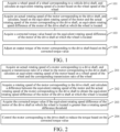
- FIG. 2 is a step flowchart of a vehicle torque control method according to another embodiment of the present disclosure, which may specifically include the following steps.
- Step 201 An actual rotating speed of a motor corresponding to a drive shaft is acquired, and a transmission ratio of a wheel to the motor corresponding to the drive shaft is acquired; and an equivalent rotating speed of the motor is calculated based on a wheel speed of the wheel and the corresponding transmission ratio of the wheel.
- wheel speeds of wheels can be collected by an in-vehicle wheel speed sensor, and the collected wheel speed of each wheel is filtered.
- a filtering method is not limited to first-order low-pass filtering, mean filtering and Kalman filtering.
- the transmission ratios are greater than 1.
- Step 202 A rotating speed of the motor corresponding to the drive shaft is acquired, and a difference between the equivalent rotating speed of the motor and the actual rotating speed of the motor corresponding to the drive shaft is calculated to obtain the equivalent rotating speed difference of the motor of the drive shaft at which the wheel is located.
- rotating speeds of corresponding motors can be collected based on the motor resolver sensor.
- the collected rotating speeds of the front axle motor and the rear axle motor are set to ⁇ mf and ⁇ mr .
- the rotating speeds of the motors are filtered.
- the filtering method is not limited to first-order low-pass filtering, mean filtering and Kalman filtering.
- a motor In a non-slip state, a motor is connected to the drive shaft by a differential.
- a relationship between the equivalent rotating speed of the wheel speed of each front wheel and the rotating speed of the motor of the front wheel is shown in formula (3), and a relationship between the equivalent rotating speed of the wheel speed of each rear wheel and the rotating speed of the motor of the rear wheel is shown in formula (4).
- the difference between the equivalent rotating speed of the motor and the actual rotating speed of the motor corresponding to the drive shaft is calculated to obtain the equivalent rotating speed difference of the motor of the drive shaft at which the wheel is located, and the equivalent rotating speed differences of the motors of the drive shafts where the left front wheel, the right front wheel, the left rear wheel and the right rear wheel are respectively located are calculated by formulas (5) and (6):
- ⁇ ⁇ fl ⁇ fleq ⁇ ⁇ mf
- ⁇ ⁇ fr ⁇ freq ⁇ ⁇ mf
- ⁇ ⁇ rl ⁇ rleq ⁇ ⁇ mr
- ⁇ ⁇ rr ⁇ rreq ⁇ ⁇ mr
- ⁇ ⁇ fl , ⁇ ⁇ fr , , ⁇ ⁇ rl and ⁇ ⁇ rr denote the equivalent rotating speed differences of left front wheel, the right front wheel, the left rear wheel and the right rear wheel respectively.
- whether a wheel slips is determined by the equivalent rotating speed difference of the motor.
- the motor rotating speed sensor can identify vehicle slipping earlier and improve real-time performance and accuracy of control.
- Step 203 The corrected torque value is acquired if the equivalent rotating speed difference of the motor of the drive shaft at which the wheel is located is greater than a rotating speed difference threshold.
- a rotating speed difference threshold may be set based on the rotating speed of the motor of the shaft where the wheel is located.
- the equivalent rotating speed difference is greater than the rotating speed difference threshold, it can be determined that the drive shaft where the wheel is located slips and needs to be corrected, and the corrected torque value can be calculated based on the equivalent rotating speed difference.
- that the corrected torque value is acquired may include:
- the corresponding corrected torque value is calculated based on the following formula (7):
- ⁇ T fl k 1 ⁇ ⁇ ⁇ fl + k 2 ⁇ ⁇ ⁇ fl ⁇ D 1
- k 1 and k 2 are a proportional coefficient and a differential coefficient and can be obtained by looking up a table
- D 1 is an equivalent rotating speed difference of the motor corresponding to the drive shaft at a previous sampling time
- ⁇ ⁇ fl is an equivalent rotating speed difference of the motor corresponding to the drive shaft at a current time
- ⁇ T fl is the corrected torque value.
- step 103 may include the following substeps S21 and S22.
- Substep S21 A wheel acceleration change rate of the wheel is acquired.
- derivation can be performed based on the wheel speeds of the wheels obtained earlier to obtain accelerations a fl , a fr , a rl , a rr of the wheels, which denote the wheel accelerations of the left front wheel, the right front wheel, the left rear wheel and the right rear wheel respectively, and then the wheel acceleration change rate can be calculated based on the wheel accelerations of the left front wheel, the right front wheel, the left rear wheel and the right rear wheel.
- Substep S22 The corrected torque value is acquired if the equivalent rotating speed difference of the motor of the drive shaft at which the wheel is located is greater than the rotating speed difference threshold and the wheel acceleration change rate is greater than a wheel acceleration change rate threshold.
- whether the motor of the drive shaft where the wheel is located slips may alternatively be determined based on another method, that is, a rotating speed difference threshold can be set based on the rotating speed of the motor of the shaft where the wheel is located.
- rotating speed difference thresholds S1, S2, S5 and S6 (S5>S 1>0, S6>S2>0) and wheel acceleration change rate thresholds A1 and A2 (A1>0, A2>0) are preset.
- S1 ⁇ ⁇ fl ⁇ S 5 and a fl >A1 it is determined that the left front wheel ordinarily slips, and when ⁇ ⁇ fl >S5, it is determined that the vehicle severely slips.
- S2 ⁇ ⁇ fr ⁇ S6 and a fl >A2 it is determined that the right front wheel ordinarily slips, and when ⁇ ⁇ fr >S6, it is determined that the vehicle severely slips.
- the left front wheel or the right front wheel ordinarily or severely slips it is determined that the front axle slips, otherwise, it is determined that no front axle slips.
- Rotating speed difference thresholds S3, S4, S7 and S8 (S7>S3>0, S8>S4>0) and wheel acceleration change rate thresholds A3 and A4 (A3>0, A4>0) are preset.
- S3 ⁇ ⁇ ⁇ rl ⁇ S7 and a rl >A3 it is determined that the left rear wheel ordinarily slips, and when ⁇ ⁇ rl >S7, it is determined that the vehicle severely slips.
- S4 ⁇ ⁇ ⁇ rr ⁇ S8 and a rr >A4 it is determined that the right rear wheel ordinarily slips, and when ⁇ ⁇ rr >S8, it is determined that the vehicle severely slips.
- the left rear wheel or the right rear wheel ordinarily or severely slips it is determined that the rear axle slips, otherwise, it is determined that no rear axle slips.
- Step 204 The motor correspond to the drive shaft is controlled to reduce the torque based on the corrected torque value.
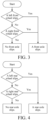
- FIG. 3 is a flowchart showing determining of slip of a front axle of a vehicle according to an embodiment of the present disclosure.
- whether wheels corresponding to a front drive shaft slip can be determined based on a comparison between the equivalent rotating speed difference of the front wheels and the rotating speed difference threshold in step 202. If any wheel at the front drive shaft slips, it is determined that the front drive shaft slips. For example, when S 1 ⁇ ⁇ fl ⁇ S5 and a fl >A1, the left front wheel slips, indicating that the front axle slips. When neither of both wheels of the front drive shaft slips, it is determined that no front drive shaft slips.
- FIG. 4 is a flowchart showing determining of slip of a rear axle of a vehicle according to an embodiment of the present disclosure.
- whether wheels corresponding to a rear drive shaft slip can be determined based on a comparison between the equivalent rotating speed difference of the rear wheels and the rotating speed difference threshold in step 202. If any wheel at the rear drive shaft slips, it is determined that the rear drive shaft slips. For example, when S3 ⁇ ⁇ rl ⁇ S7 and a rl >A3, it is determined that the left rear wheel ordinarily slips, and the rear axle slips. When neither of both wheels of the rear drive shaft slips, it is determined that no front drive shaft slips.
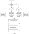
- FIG. 5 is a flowchart showing a front axle and rear axle torque control policy according to an embodiment of the present disclosure.
- the torque of the slipping drive shaft is reduced, and the torque of the non-slipping drive shaft is increased.
- both the front drive shaft and the rear drive shaft slip the torques of the front drive shaft and the rear drive shaft are reduced at the same time.
- neither of the front drive shaft and the rear drive shaft slips neither of the torques of the front drive shaft and the rear drive shaft is reduced, and the front drive shaft and the rear drive shaft each respond to a throttle torque.
- the motor corresponding to the drive shaft is controlled to reduce the torque. For example, when it is determined that the left front wheel or the right front wheel slips while no wheel at the rear axle slips, the front axle motor reduces the torque by a value that is the corrected torque calculated for the slipping wheel, and the rear axle motor increases the torque by the corresponding value.
- the rear axle motor When it is determined that the left rear wheel slips or the right rear wheel slips while no wheel at the front axle slips, the rear axle motor reduces the torque by a value that is the corrected torque calculated for the slipping wheel.
- the front axle motor increases the torque by the corresponding value.
- the torque can be transferred from one end with low adhesion to the other end with high adhesion, that is, the torque of the motor of the drive shaft at which a slipping wheel is located is reduced, and the torque of the motor of the drive shaft at which a non-slipping wheel is located is increased. This avoids a loss of power, and can ensure power of the whole vehicle while restraining the slipping, thereby ensuring power performance of the vehicle.
- each of the torques of the front axle motor and the rear axle motor is reduced by a value that is a corrected torque calculated for the slipping wheel. Otherwise, the front axle motor and the rear axle motor each respond to the throttle torque.
- the drive shaft includes a front axle and a rear axle.
- Step 204 may include substep S23.
- Step S23 When an equivalent rotating speed difference of a motor corresponding to the front axle is greater than the rotating speed difference threshold, the motor of the front axle is controlled to reduce a torque based on the corrected torque value, or when an equivalent rotating speed difference of a motor corresponding to the rear axle is greater than the rotating speed difference threshold, the motor of the rear axle is controlled to reduce a torque based on the corrected torque value, or when equivalent rotating speed differences of motors corresponding to the front axle and the rear axle are both greater than the rotating speed difference threshold, the motors of the front axle and the rear axle are controlled to reduce torques based on the corrected torque value.
- the motor of the front axle is controlled to reduce a torque based on the corrected torque value, or that when an equivalent rotating speed difference of a motor corresponding to the rear axle is greater than the rotating speed difference threshold, the motor of the rear axle is controlled to reduce a torque based on the corrected torque value may include:
- the motor corresponding to the front axle When the equivalent rotating speed difference of the motor corresponding to the front axle is greater than the rotating speed difference threshold, the motor corresponding to the front axle is controlled to reduce the corrected torque value, and a rear axle torque incremental value increasable by the motor corresponding to the rear axle is determined; and if the rear axle torque incremental value is great than or equal to the corrected torque value, the motor corresponding to the rear axle is controlled to increase the corrected torque value, or if the rear axle torque incremental value is less than the corrected torque value, the motor corresponding to the rear axle is controlled to increase the torque based on the rear axle torque incremental value; or when the equivalent rotating speed difference of the motor corresponding to the rear axle is greater than the rotating speed difference threshold, the motor corresponding to the rear axle is controlled to reduce the corrected torque value, and a front axle torque incremental value increasable by the motor corresponding to the front axle is determined; and if the front axle torque incremental value is great than or equal to the corrected torque value, the motor corresponding to the front axle is controlled to increase the corrected torque
- that the corrected torque value is acquired includes:
- a corrected left wheel torque value corresponding to a left wheel connected to the drive shaft is acquired, and a corrected right wheel torque value corresponding to a right wheel connected to the drive shaft is acquired. Magnitudes of the corrected left wheel torque value and the corrected right wheel torque value are determined, and the larger value is taken as the corrected torque value, thereby better restraining or eliminating slipping.
- both wheels corresponding to the drive shaft are about to slip
- corrected wheel torque values of both wheels can be obtained, and the larger one is used as the corrected torque value to adjust the torque of the motor of the drive shaft corresponding to the wheel.
- the corrected torque value of the left front wheel is 30 N*m
- the corrected torque value of the right front wheel is 40 N*m.
- the corrected torque value of the motor on the front axle is 40 N*m.
- a torque lower limit value is determined.
- the output torque of the motor corresponding to the drive shaft is controlled to be the torque lower limit value.
- a slip state of each wheel may fall into severe slip and ordinary slip.
- lower limit values of the output torque of the motor corresponding to the drive shaft are different.
- the lower limit value is 0.
- the output torque of the motor corresponding to the drive shaft may not be able to balance the equivalent rotating speed difference after being reduced to 0. In this case, the output torque needs to continue to be reduced to a physical limit value of motor reversal.
- the torque lower limit value can be self-adaptive based on a slipping degree of the vehicle, thereby avoiding a case that the torque can only be adjusted to 0 during severe slip of the vehicle, but the equivalent rotating speed difference of the motor of the drive shaft corresponding to a slipping wheel has not been adjusted well. This improves efficiency of torque adjustment of the motor of the drive shaft corresponding to the slipping wheel.
- the torque lower limit value is 0 when the equivalent rotating speed difference of the motor corresponding to the drive shaft is greater than a first rotating speed difference threshold and less than a second rotating speed difference threshold.
- the second rotating speed difference threshold is greater than the first rotating speed difference threshold.
- the torque lower limit value is determined as a torque limit value of motor reversal when the equivalent rotating speed difference of the motor corresponding to the drive shaft is greater than the second rotating speed difference threshold.
- FIG. 6 shows a vehicle torque control apparatus according to the present disclosure, which includes:
- the calculation module 302 may include: an equivalent rotating speed difference calculation submodule, configured to calculate a difference between the equivalent rotating speed of the motor and the actual rotating speed of the motor corresponding to the drive shaft to obtain the equivalent rotating speed difference of the motor of the drive shaft at which the wheel is located.
- the determining module 303 may include: a first determining submodule, configured to acquire the corrected torque value if the equivalent rotating speed difference of the motor of the drive shaft at which the wheel is located is greater than a rotating speed difference threshold.
- the determining module 303 may include:
- control module 304 may include: a first adjustment submodule, configured to control the motor corresponding to the drive shaft to reduce the torque based on the corrected torque value.
- the drive shaft includes a front axle and a rear axle; and the first adjustment submodule may include:
- the first adjustment unit may include:
- the calculation module 302 may include:
- the determining module 303 may include: a fourth determining submodule, configured to calculate the corresponding corrected torque value based on the following formula:
- ⁇ T fl k 1 * ⁇ ⁇ fl + k 2 * ( ⁇ ⁇ fl - D 1 ), where k 1 and k 2 are a proportional coefficient and a differential coefficient and can be obtained by looking up a table, D 1 is an equivalent rotating speed difference of the motor corresponding to the drive shaft at a previous sampling time, ⁇ ⁇ fl is an equivalent rotating speed difference of the motor corresponding to the drive shaft at a current time, and ⁇ T fl is the corrected torque value.
- the determining module 303 may include:
- control module 304 may include:
- the torque lower limit value determining submodule may include:
- an embodiment of the present disclosure discloses a computer-readable storage medium.
- the computer-readable storage medium stores a computer program.
- the steps of the vehicle torque control method described above are implemented when the computer program is executed by a processor.
- an embodiment of the present disclosure discloses an electronic device, including a processor, a memory and a computer program stored in the memory and executable on the processor. The steps of the vehicle torque control method described above are implemented when the computer program is executed by the processor.
- an embodiment of the present disclosure discloses a vehicle.
- the vehicle includes a front motor, a rear motor and a controller.
- the controller is configured to implement the steps of the vehicle torque control method described above.
- the embodiments of the present disclosure may be provided as methods, apparatuses, or computer program products. Therefore, the present disclosure may use a form of hardware-only embodiments, software-only embodiments, or embodiments combining software and hardware. In addition, the embodiments of the present disclosure may use a form of a computer program product implemented on one or more computer-usable storage media (including but not limited to a disk memory, a CD-ROM and an optical memory) including computer-usable program code.
- a computer-usable storage media including but not limited to a disk memory, a CD-ROM and an optical memory
- These computer program instructions may be provided to a processor of a general purpose computer, a special purpose computer, an embedded processor or other programmable data processing terminal devices to produce a machine, so that the instructions executed by a processor of a computer or other programmable data processing terminal devices are used to produce an apparatus configured to implement functions specified in one or more processes of the flowcharts and/or one or more blocks of the block diagrams.
- These computer program instructions may alternatively be stored in a computer-readable memory that can instruct a computer or other programmable data processing terminal devices to operate in a specific manner, so that the instructions stored in the computer-readable memory are used to produce a product including an instruction apparatus, and the instruction apparatus implements functions specified in one or more processes of the flowcharts and/or one or more blocks of the block diagrams.
- These computer program instructions may alternatively be loaded on a computer or other programmable data processing terminal devices, so that a series of operation steps are performed on the computer or other programmable terminal devices to produce computer-implemented processing, and therefore the instructions executed on the computer or other programmable terminal devices are used to provide steps for implementing functions specified in one or more processes of the flowcharts and/or one or more blocks of the block diagrams.
Landscapes
- Engineering & Computer Science (AREA)
- Transportation (AREA)
- Mechanical Engineering (AREA)
- Power Engineering (AREA)
- Life Sciences & Earth Sciences (AREA)
- Sustainable Development (AREA)
- Sustainable Energy (AREA)
- Automation & Control Theory (AREA)
- Electric Propulsion And Braking For Vehicles (AREA)
Abstract
A vehicle torque control method, comprising: step 101, acquiring the wheel speed of a wheel corresponding to a vehicle driver shaft, and according to the wheel speed of the wheel, calculating the equivalent rotating speed of a motor; step 102, acquiring the actual rotating speed of the motor corresponding to the driver shaft, and according to the equivalent rotating speed of the motor and the actual rotating speed of the motor corresponding to the driver shaft, calculating the equivalent rotating speed difference of the motor of the driver shaft to which the wheel is mounted; step 103, acquiring a corrected torque value according to the equivalent rotating speed difference of the motor of the driver shaft to which the wheel is mounted; and step 104, according to the corrected torque value, adjusting the output torque of the motor corresponding to the driver shaft. Also disclosed are a vehicle torque control apparatus, an electronic device, a storage medium, and a vehicle. The method reduces the difficulty of calculating the slip ratio. According to the state of the single wheel and the state of the single shaft, the torque of the motor of the driver shaft corresponding to a slipping wheel can be adjusted, and the adhesion utilization rate of the whole vehicle is improved, thereby improving the power performance of the whole vehicle, and avoiding the power loss caused by controlling torque reduction by means of the slip ratio.
Description
- The present disclosure is provided based on
Chinese Patent Application No. 202210552589.0 filed on May 20, 2022 - The present disclosure relates to the technical field of vehicles, and specifically, to a vehicle torque control method and apparatus, an electronic device, and a storage medium.
- With the development of new energy vehicle technologies, requirements for safety and comfort of new energy vehicles are increasingly high. At present, most new energy vehicles are four-wheel drive vehicles, and each wheel can obtain power. Therefore, a response speed of a single wheel is relatively fast, and the wheel is susceptible to slip. In the related art, to solve this problem, whether the vehicle slips is generally determined by a slip ratio, so as to control the vehicle slip. However, a vehicle speed needs to be estimated when the slip ratio is calculated, which increases the difficulty of an algorithm.
- In view of the above problems, embodiments of the present disclosure are proposed to provide a vehicle torque control method and apparatus, an electronic device, and a storage medium to overcome or at least partially solve the above problems.
- To solve the above problems, an embodiment of the present disclosure discloses a vehicle torque control method. The method includes:
A wheel speed of a wheel corresponding to a vehicle drive shaft is acquired, and an equivalent rotating speed of a motor is calculated based on the wheel speed of the wheel. - An actual rotating speed of the motor corresponding to the drive shaft is acquired, and based on the equivalent rotating speed of the motor and the actual rotating speed of the motor corresponding to the drive shaft, an equivalent rotating speed difference of the motor of the drive shaft at which the wheel is located is calculated.
- A corrected torque value is acquired based on the equivalent rotating speed difference of the motor of the drive shaft at which the wheel is located.
- An output torque of the motor corresponding to the drive shaft is adjusted based on the corrected torque value.
- In an embodiment, that based on the equivalent rotating speed of the motor and the actual rotating speed of the motor corresponding to the drive shaft, an equivalent rotating speed difference of the motor of the drive shaft at which the wheel is located is calculated includes:
A difference between the equivalent rotating speed of the motor and the actual rotating speed of the motor corresponding to the drive shaft is calculated to obtain the equivalent rotating speed difference of the motor of the drive shaft at which the wheel is located. - In an embodiment, that a corrected torque value is acquired based on the equivalent rotating speed difference of the motor of the drive shaft at which the wheel is located includes:
- The corrected torque value is acquired if the equivalent rotating speed difference of the motor of the drive shaft at which the wheel is located is greater than a rotating speed difference threshold.
- In an embodiment, that a corrected torque value is acquired based on the equivalent rotating speed difference of the motor of the drive shaft at which the wheel is located includes:
A wheel acceleration change rate of the wheel is acquired. - The corrected torque value is acquired if the equivalent rotating speed difference of the motor of the drive shaft at which the wheel is located is greater than the rotating speed difference threshold and the wheel acceleration change rate is greater than a wheel acceleration change rate threshold.
- In an embodiment, that an output torque of the motor corresponding to the drive shaft is adjusted based on the corrected torque value includes:
The motor corresponding to the drive shaft is controlled to reduce the torque based on the corrected torque value. - In an embodiment, the drive shaft includes a front axle and a rear axle. That the motor corresponding to the drive shaft is controlled to reduce the torque based on the corrected torque value includes:
When an equivalent rotating speed difference of a motor corresponding to the front axle is greater than the rotating speed difference threshold, the motor of the front axle is controlled to reduce a torque based on the corrected torque value, or - when an equivalent rotating speed difference of a motor corresponding to the rear axle is greater than the rotating speed difference threshold, the motor of the rear axle is controlled to reduce a torque based on the corrected torque value, or
- when equivalent rotating speed differences of motors corresponding to the front axle and the rear axle are both greater than the rotating speed difference threshold, the motors of the front axle and the rear axle are controlled to reduce torques based on the corrected torque value.
- In an embodiment, that when an equivalent rotating speed difference of a motor corresponding to the front axle is greater than the rotating speed difference threshold, the motor of the front axle is controlled to reduce a torque based on the corrected torque value, or that when an equivalent rotating speed difference of a motor corresponding to the rear axle is greater than the rotating speed difference threshold, the motor of the rear axle is controlled to reduce a torque based on the corrected torque value includes:
When the equivalent rotating speed difference of the motor corresponding to the front axle is greater than the rotating speed difference threshold, the motor corresponding to the front axle is controlled to reduce the corrected torque value, and a rear axle torque incremental value increasable by the motor corresponding to the rear axle is determined; and if the rear axle torque incremental value is great than or equal to the corrected torque value, the motor corresponding to the rear axle is controlled to increase the corrected torque value, or if the rear axle torque incremental value is less than the corrected torque value, the motor corresponding to the rear axle is controlled to increase the torque based on the rear axle torque incremental value; or
when the equivalent rotating speed difference of the motor corresponding to the rear axle is greater than the rotating speed difference threshold, the motor corresponding to the rear axle is controlled to reduce the corrected torque value, and a front axle torque incremental value increasable by the motor corresponding to the front axle is determined; and if the front axle torque incremental value is great than or equal to the corrected torque value, the motor corresponding to the front axle is controlled to increase the corrected torque value, or if the front axle torque incremental value is less than the corrected torque value, the motor corresponding to the front axle is controlled to increase the torque based on the front axle torque incremental value. - In an embodiment, that an equivalent rotating speed of a motor is calculated based on the wheel speed of the wheel includes:
A transmission ratio of the wheel to the motor corresponding to the drive shaft is acquired. - The equivalent rotating speed of the motor is calculated based on the wheel speed of the wheel and the corresponding transmission ratio of the wheel.
- In an embodiment, that a corrected torque value is acquired includes:
The corresponding corrected torque value is calculated based on the following formula: - Δ Tfl = k 1 *△ ωfl + k 2 * (△ωfl - D 1), where k 1 and k 2 are a proportional coefficient and a differential coefficient, D 1 is an equivalent rotating speed difference of the motor corresponding to the drive shaft at a previous sampling time, △ωfl is an equivalent rotating speed difference of the motor corresponding to the drive shaft at a current time, and △ Tfl is the corrected torque value.
- In an embodiment, that a corrected torque value is acquired includes:
A corrected left wheel torque value corresponding to a left wheel connected to the drive shaft is acquired, and a corrected right wheel torque value corresponding to a right wheel connected to the drive shaft is acquired. - Magnitudes of the corrected left wheel torque value and the corrected right wheel torque value are determined, and the larger value is taken as the corrected torque value.
- In an embodiment, that an output torque of the motor corresponding to the drive shaft is adjusted based on the corrected torque value includes:
A torque lower limit value is determined. - If a current output torque of the motor corresponding to the drive shaft is less than or equal to the torque lower limit value after the corrected torque value is reduced, the output torque of the motor corresponding to the drive shaft is controlled to be the torque lower limit value.
- In an embodiment, that a torque lower limit value is determined includes:
It is determined that the torque lower limit value is 0 when the equivalent rotating speed difference of the motor corresponding to the drive shaft is greater than a first rotating speed difference threshold and less than a second rotating speed difference threshold. The second rotating speed difference threshold is greater than the first rotating speed difference threshold. - The torque lower limit value is determined as a torque limit value of motor reversal when the equivalent rotating speed difference of the motor corresponding to the drive shaft is greater than the second rotating speed difference threshold.
- In another aspect, an embodiment of the present disclosure discloses a vehicle torque control apparatus, including:
- an information acquisition module, configured to acquire a wheel speed of a wheel corresponding to a vehicle drive shaft, and acquire a rotating speed of a motor corresponding to the drive shaft;
- a calculation module, configured to calculate an equivalent rotating speed based on the wheel speed of the wheel, and calculate, based on the rotating speed of the wheel and the rotating speed of the motor corresponding to the drive shaft, an equivalent rotating speed difference of the motor of the drive shaft at which the wheel is located;
- a determining module, configured to acquire a corrected torque value based on the equivalent rotating speed difference of the motor of the drive shaft at which the wheel is located; and
- a control module, configured to adjust an output torque of the motor corresponding to the drive shaft based on the corrected torque value.
- In an embodiment, the calculation module includes:
an equivalent rotating speed difference calculation submodule, configured to calculate a difference between the equivalent rotating speed of the motor and the actual rotating speed of the motor corresponding to the drive shaft to obtain the equivalent rotating speed difference of the motor of the drive shaft at which the wheel is located. - In an embodiment, the determining module includes:
a first determining submodule, configured to acquire the corrected torque value if the equivalent rotating speed difference of the motor of the drive shaft at which the wheel is located is greater than a rotating speed difference threshold. - In an embodiment, the determining module includes:
- a second determining submodule, configured to acquire a wheel acceleration change rate of the wheel; and
- a third determining submodule, configured to acquire the corrected torque value if the equivalent rotating speed difference of the motor of the drive shaft at which the wheel is located is greater than the rotating speed difference threshold and the wheel acceleration change rate is greater than a wheel acceleration change rate threshold.
- In an embodiment, the control module includes:
a first adjustment submodule, configured to control the motor corresponding to the drive shaft to reduce the torque based on the corrected torque value. - In an embodiment, the drive shaft includes a front axle and a rear axle; and the first adjustment submodule includes:
- a first adjustment unit, configured to control, when an equivalent rotating speed difference of a motor corresponding to the front axle is greater than the rotating speed difference threshold, the motor of the front axle to reduce a torque based on the corrected torque value, or
- controlling, when an equivalent rotating speed difference of a motor corresponding to the rear axle is greater than the rotating speed difference threshold, the motor of the rear axle to reduce a torque based on the corrected torque value, or
- controlling, when equivalent rotating speed differences of motors corresponding to the front axle and the rear axle are both greater than the rotating speed difference threshold, the motors of the front axle and the rear axle to reduce torques based on the corrected torque value.
- In an embodiment, the first adjustment unit includes:
- a first adjustment subunit, configured to control, when the equivalent rotating speed difference of the motor corresponding to the front axle is greater than the rotating speed difference threshold, the motor corresponding to the front axle to reduce the corrected torque value, and determine a rear axle torque incremental value increasable by the motor corresponding to the rear axle; and control, if the rear axle torque incremental value is great than or equal to the corrected torque value, the motor corresponding to the rear axle to increase the corrected torque value, or control, if the rear axle torque incremental value is less than the corrected torque value, the motor corresponding to the rear axle to increase the torque based on the rear axle torque incremental value; and
- a second adjustment subunit, configured to control, when the equivalent rotating speed difference of the motor corresponding to the rear axle is greater than the rotating speed difference threshold, the motor corresponding to the rear axle to reduce the corrected torque value, and determine a front axle torque incremental value increasable by the motor corresponding to the front axle; and control, if the front axle torque incremental value is great than or equal to the corrected torque value, the motor corresponding to the front axle to increase the corrected torque value, or control, if the front axle torque incremental value is less than the corrected torque value, the motor corresponding to the front axle to increase the torque based on the front axle torque incremental value.
- In an embodiment, the calculation module includes:
- a transmission ratio acquisition submodule, configured to acquire a transmission ratio of the wheel to the motor corresponding to the drive shaft; and
- an equivalent rotating speed calculation submodule, configured to calculate the equivalent rotating speed of the motor based on the wheel speed of the wheel and the corresponding transmission ratio.
- In an embodiment, the determining module includes:
a fourth determining submodule, configured to calculate the corresponding corrected torque value based on the following formula: - △ Tfl = k 1 *△ ωfl + k 2 * (△ ωfl - D 1), where k 1 and k 2 are a proportional coefficient and a differential coefficient, D 1 is an equivalent rotating speed difference of the motor corresponding to the drive shaft at a previous sampling time, △ωfl is an equivalent rotating speed difference of the motor corresponding to the drive shaft at a current time, and △ Tfl is the corrected torque value.
- In an embodiment, the determining module includes:
- a submodule for acquiring a corrected wheel torque value, configured to acquire a corrected left wheel torque value corresponding to a left wheel connected to the drive shaft, and acquire a corrected right wheel torque value corresponding to a right wheel connected to the drive shaft; and
- a fifth determining submodule, configured to determine magnitudes of the corrected left wheel torque value and the corrected right wheel torque value, and take the larger value as the corrected torque value.
- In an embodiment, the control module includes:
- a torque lower limit value determining submodule, configured to determine a torque lower limit value; and
- a second adjustment submodule, configured to control, if a current output torque of the motor corresponding to the drive shaft is less than or equal to the torque lower limit value after the corrected torque value is reduced, the output torque of the motor corresponding to the drive shaft to be the torque lower limit value.
- In an embodiment, the torque lower limit value determining submodule includes:
- a first torque lower limit value determining unit, configured to determine that the torque lower limit value is 0 when the equivalent rotating speed difference of the motor corresponding to the drive shaft is greater than a first rotating speed difference threshold and less than a second rotating speed difference threshold; the second rotating speed difference threshold being greater than the first rotating speed difference threshold; and
- a second torque lower limit value determining unit, configured to determine the torque lower limit value as a torque limit value of motor reversal when the equivalent rotating speed difference of the motor corresponding to the drive shaft is greater than the second rotating speed difference threshold.
- In another aspect, an embodiment of the present disclosure discloses an electronic device, including a processor, a memory and a computer program stored in the memory and executable on the processor. The steps of the vehicle torque control method described above are implemented when the computer program is executed by the processor.
- In another aspect, an embodiment of the present disclosure discloses a computer-readable storage medium. The computer-readable storage medium stores a computer program. The steps of the vehicle torque control method described above are implemented when the computer program is executed by a processor.
- In another aspect, an embodiment of the present disclosure discloses a vehicle. The vehicle includes a front motor, a rear motor and a controller. The controller is configured to implement the steps of the vehicle torque control method described above.
- The embodiments of the present disclosure have the following advantages.
- According to the present disclosure, an equivalent rotating speed difference of a drive shaft at which a wheel is located can be calculated by a wheel speed of the wheel and a rotating speed of the drive shaft, and whether the shaft at which the wheel is located needs torque reduction can be determined based on the equivalent rotating speed difference, so that the difficulty of calculating a slip ratio is reduced. According to the present disclosure, a torque of a motor of a drive shaft corresponding to a slipping wheel can be adjusted based on a state of the single wheel and a state of the single shaft, so that an adhesion utilization rate of a whole vehicle is improved, thereby improving power performance of the whole vehicle, and avoiding power loss caused by control of torque reduction through the slip ratio.
-
-
FIG. 1 is a step flowchart of a vehicle torque control method according to an embodiment of the present disclosure; -
FIG. 2 is a step flowchart of a vehicle torque control method according to another embodiment of the present disclosure; -
FIG. 3 is a flowchart showing steps of determining slip of a front axle of a vehicle according to an embodiment of the present disclosure; -
FIG. 4 is a flowchart showing steps of determining slip of a rear axle of a vehicle according to an embodiment of the present disclosure; -
FIG. 5 is a flowchart showing a front axle and rear axle torque control policy according to an embodiment of the present disclosure; and -
FIG. 6 is a structural block diagram of a vehicle torque control apparatus according to an embodiment of the present disclosure. - To make the above objective, features and advantages of the present disclosure clearer and more comprehensible, the present disclosure is further described in detail below with reference to the accompanying drawings and specific implementations.
- In the related art, a wheel slip ratio is acquired by a front wheel rotating speed / rear wheel rotating speed / vehicle speed. When the slip ratio is greater than a threshold, a torque of a motor is reduced, to control slip of a vehicle. However, a slip state of a single shaft and a single wheel and requirements for adjusting torques of a front axle motor and a rear axle motor are not considered, which reduces power performance of the whole vehicle. Moreover, the vehicle speed needs to be estimated when the slip ratio is calculated, which increases the difficulty of an algorithm.
- One of the core ideas of embodiments of the present disclosure is to calculate, based on an equivalent rotating speed of a wheel speed of a wheel and a rotating speed of a motor of a drive shaft at which the wheel is located, an equivalent rotating speed difference of the motor of the drive shaft at which the wheel is located, calculate a corresponding corrected torque based on the equivalent rotating speed difference, and adjust a torque of the motor of the drive shaft at which a slipping wheel is located based on the corrected torque.
-
FIG. 1 is a step flowchart of a vehicle torque control method according to an embodiment of the present disclosure, which may specifically include the following steps. - Step 101: A wheel speed of a wheel corresponding to a vehicle drive shaft is acquired, and an equivalent rotating speed of a motor is calculated based on the wheel speed of the wheel.
- In the embodiment of the present disclosure, the vehicle may be a four-wheel drive vehicle or a two-wheel drive vehicle. The two front-wheel drive vehicle means that two front wheels or two rear wheels are driven by one motor. Four-wheel drive vehicles may fall into dual-motor drive, three-motor drive and four-motor drive. A dual-motor four-wheel drive vehicle means that one motor drives two front wheels and the other motor drives two rear wheels. A three-motor four-wheel drive vehicle means one motor drives two wheels at a shaft, and two wheels on the other side are driven by two motors. The four-motor four-wheel drive vehicle means two motors drive two front wheels and two motors drive two rear wheels. It should be noted that the examples in the embodiment of the present disclosure are all explained with a dual-motor four-wheel drive vehicle (that is, a front axle drives two wheels by one motor, and a rear axle drives two wheels by the other motor) as an example.
- In sensors of the vehicle, a wheel speed sensor has a small number of (usually 8 or 16) teeth of a tooth ring and low resolution (usually 45° or 22.5°), and therefore cannot accurately and effectively identify a rapid and small rotating speed fluctuation, but a motor rotating speed sensor features high resolution (usually about 360°/4096 ≈ 0.088°), and therefore can accurately and effectively identify a small fluctuation. Therefore, the measurement of the motor rotating speed is faster and more accurate than that of the wheel speed. In addition, a torque at the motor end is first transmitted to a speed reducer first and then to left and right wheels through mechanical transmission, there is a certain delay in this process. A changing trend of the wheel speed of the wheel can be predicted in advance by the motor rotating speed, which is more conducive to vehicle control.
- Therefore, the wheel speed of each wheel of the vehicle can be collected by the wheel speed sensor, and a transmission ratio between the wheel and the motor can be inquired. Based on the wheel speed of the wheel and the transmission ratio, the equivalent rotating speed of the motor is calculated when the wheel speed of the wheel is equivalent to the rotating speed at the motor end corresponding to the drive shaft.
- Step 102: An actual rotating speed of the motor corresponding to the drive shaft is acquired, and an equivalent rotating speed difference of the motor of the drive shaft at which the wheel is located is calculated based on the equivalent rotating speed of the motor and the actual rotating speed of the motor corresponding to the drive shaft.
- In the embodiment of the present disclosure, the rotating speed of the motor corresponding to the vehicle drive shaft can be collected by a motor resolver sensor, and a difference between the equivalent rotating speed of the wheel and the rotating speed of the motor corresponding to the drive shaft can be calculated, so that the equivalent rotating speed difference of the motor of the drive shaft at which the wheel is located can be obtained.
- Step 103: A corrected torque value is acquired based on the equivalent rotating speed difference of the motor of the drive shaft at which the wheel is located.
- Specifically, whether the wheel slips can be determined based on an equivalent shaft speed difference, and then the corrected torque value corresponding to eliminating the equivalent rotating speed difference can be calculated based on the equivalent rotating speed difference and an equivalent rotating speed difference at a previous time.
- Step 104: An output torque of the motor corresponding to the drive shaft is adjusted based on the corrected torque value.
- In the embodiment of the present disclosure, a torque of a motor of a drive shaft at which a slipping wheel is located can be reduced based on the corrected torque value. In addition, a torque of a motor of a drive shaft at which a non-slipping wheel is located can be increased, thereby avoiding the slip of the wheel.
- According to the present disclosure, the equivalent rotating speed difference of the motor of the drive shaft at which a wheel is located can be calculated by a wheel speed of the wheel and a rotating speed of the drive shaft, and whether the shaft at which the wheel is located slips can be determined based on the equivalent rotating speed difference, so as to determine whether the torque needs to be reduced, so that the difficulty of calculating a slip ratio is reduced. According to the present disclosure, a torque of a motor of a drive shaft where a slipping wheel is located can be adjusted based on a state of the single wheel and a state of the single shaft, so that an adhesion utilization rate of a whole vehicle is improved, thereby improving power performance of the whole vehicle, and avoiding power loss caused by torque reduction through the slip ratio.
- It can be understood that the wheel speed of the wheel corresponding to the drive shaft mentioned above means the wheel speed of the wheel connected to the drive shaft. The wheel speed of one of wheels connected to the drive shaft may be acquired, or wheel speeds of both wheels may be acquired, and an equivalent rotating speed of the motor corresponding to the wheels is calculated by the wheel speed and is compared with an actual rotating speed of the motor, so that which wheel on the drive shaft slips can be determined.
-
FIG. 2 is a step flowchart of a vehicle torque control method according to another embodiment of the present disclosure, which may specifically include the following steps. - Step 201: An actual rotating speed of a motor corresponding to a drive shaft is acquired, and a transmission ratio of a wheel to the motor corresponding to the drive shaft is acquired; and an equivalent rotating speed of the motor is calculated based on a wheel speed of the wheel and the corresponding transmission ratio of the wheel.
- In an example, wheel speeds of wheels, ωfl , ωfr , ωrl and ωrr , can be collected by an in-vehicle wheel speed sensor, and the collected wheel speed of each wheel is filtered. A filtering method is not limited to first-order low-pass filtering, mean filtering and Kalman filtering.
- A transmission ratio between each wheel and the motor can be inquired, and the equivalent rotating speed of each wheel is calculated by the following formulas (1) and (2):


- Step 202: A rotating speed of the motor corresponding to the drive shaft is acquired, and a difference between the equivalent rotating speed of the motor and the actual rotating speed of the motor corresponding to the drive shaft is calculated to obtain the equivalent rotating speed difference of the motor of the drive shaft at which the wheel is located.
- In the embodiment of the present disclosure, rotating speeds of corresponding motors can be collected based on the motor resolver sensor. The collected rotating speeds of the front axle motor and the rear axle motor are set to ωmf and ωmr . The rotating speeds of the motors are filtered. The filtering method is not limited to first-order low-pass filtering, mean filtering and Kalman filtering.
- In a non-slip state, a motor is connected to the drive shaft by a differential. According to the principle of an open differential, a relationship between the equivalent rotating speed of the wheel speed of each front wheel and the rotating speed of the motor of the front wheel is shown in formula (3), and a relationship between the equivalent rotating speed of the wheel speed of each rear wheel and the rotating speed of the motor of the rear wheel is shown in formula (4).


- Therefore, there is a difference between the rotating speed of a motor and the equivalent rotating speed of the motor when a wheel slips.
- The difference between the equivalent rotating speed of the motor and the actual rotating speed of the motor corresponding to the drive shaft is calculated to obtain the equivalent rotating speed difference of the motor of the drive shaft at which the wheel is located, and the equivalent rotating speed differences of the motors of the drive shafts where the left front wheel, the right front wheel, the left rear wheel and the right rear wheel are respectively located are calculated by formulas (5) and (6):


- In the present disclosure, whether a wheel slips is determined by the equivalent rotating speed difference of the motor. Compared with the wheel speed sensor, the motor rotating speed sensor can identify vehicle slipping earlier and improve real-time performance and accuracy of control.
- Step 203: The corrected torque value is acquired if the equivalent rotating speed difference of the motor of the drive shaft at which the wheel is located is greater than a rotating speed difference threshold.
- In the embodiment of the present disclosure, a rotating speed difference threshold may be set based on the rotating speed of the motor of the shaft where the wheel is located. When the equivalent rotating speed difference is greater than the rotating speed difference threshold, it can be determined that the drive shaft where the wheel is located slips and needs to be corrected, and the corrected torque value can be calculated based on the equivalent rotating speed difference.
- In an embodiment of the present disclosure, that the corrected torque value is acquired may include: The corresponding corrected torque value is calculated based on the following formula (7):

- In an embodiment of the present disclosure,
step 103 may include the following substeps S21 and S22. - Substep S21: A wheel acceleration change rate of the wheel is acquired.
- Specifically, derivation can be performed based on the wheel speeds of the wheels obtained earlier to obtain accelerations afl, afr, arl, arr of the wheels, which denote the wheel accelerations of the left front wheel, the right front wheel, the left rear wheel and the right rear wheel respectively, and then the wheel acceleration change rate can be calculated based on the wheel accelerations of the left front wheel, the right front wheel, the left rear wheel and the right rear wheel.
- Substep S22: The corrected torque value is acquired if the equivalent rotating speed difference of the motor of the drive shaft at which the wheel is located is greater than the rotating speed difference threshold and the wheel acceleration change rate is greater than a wheel acceleration change rate threshold.
- In the embodiment of the present disclosure, whether the motor of the drive shaft where the wheel is located slips may alternatively be determined based on another method, that is, a rotating speed difference threshold can be set based on the rotating speed of the motor of the shaft where the wheel is located.
- In an example, rotating speed difference thresholds S1, S2, S5 and S6 (S5>S 1>0, S6>S2>0) and wheel acceleration change rate thresholds A1 and A2 (A1>0, A2>0) are preset. When S1<Δωfl <S5 and afl >A1, it is determined that the left front wheel ordinarily slips, and when Δωfl >S5, it is determined that the vehicle severely slips. When S2<Δωfr <S6 and afl >A2, it is determined that the right front wheel ordinarily slips, and when Δωfr >S6, it is determined that the vehicle severely slips. When the left front wheel or the right front wheel ordinarily or severely slips, it is determined that the front axle slips, otherwise, it is determined that no front axle slips.
- In an embodiment of the present disclosure, when Δωfl >S5 and afl >A1, it is determined that the vehicle severely slips, and when Δωfr >S6 and afl >A2, it is determined that the vehicle severely slips.
- Rotating speed difference thresholds S3, S4, S7 and S8 (S7>S3>0, S8>S4>0) and wheel acceleration change rate thresholds A3 and A4 (A3>0, A4>0) are preset. When S3< Δωrl <S7 and arl>A3, it is determined that the left rear wheel ordinarily slips, and when Δωrl >S7, it is determined that the vehicle severely slips. When S4<Δωrr <S8 and arr>A4, it is determined that the right rear wheel ordinarily slips, and when Δωrr >S8, it is determined that the vehicle severely slips. When the left rear wheel or the right rear wheel ordinarily or severely slips, it is determined that the rear axle slips, otherwise, it is determined that no rear axle slips.
- In an embodiment of the present disclosure, when Δωrl >S7 and arl>A3, it is determined that the vehicle severely slips, and when Δωrr >S8 and arr >A4, it is determined that the vehicle severely slips.
- Step 204: The motor correspond to the drive shaft is controlled to reduce the torque based on the corrected torque value.
-
FIG. 3 is a flowchart showing determining of slip of a front axle of a vehicle according to an embodiment of the present disclosure. - In the embodiment of the present disclosure, whether wheels corresponding to a front drive shaft slip can be determined based on a comparison between the equivalent rotating speed difference of the front wheels and the rotating speed difference threshold in
step 202. If any wheel at the front drive shaft slips, it is determined that the front drive shaft slips. For example, when S1<Δωfl <S5 and afl >A1, the left front wheel slips, indicating that the front axle slips. When neither of both wheels of the front drive shaft slips, it is determined that no front drive shaft slips. For example, when Δωfl<S1 and afl <A1, and Δωfr <S2 and afl<A2, neither of the left front wheel and the right front wheel slips, indicating that no front axle slips. -
FIG. 4 is a flowchart showing determining of slip of a rear axle of a vehicle according to an embodiment of the present disclosure. - In the embodiment of the present disclosure, whether wheels corresponding to a rear drive shaft slip can be determined based on a comparison between the equivalent rotating speed difference of the rear wheels and the rotating speed difference threshold in
step 202. If any wheel at the rear drive shaft slips, it is determined that the rear drive shaft slips. For example, when S3<Δωrl <S7 and arl>A3, it is determined that the left rear wheel ordinarily slips, and the rear axle slips. When neither of both wheels of the rear drive shaft slips, it is determined that no front drive shaft slips. For example, when Δωrl <S3 and arl <A3, and Δωrr <S4 and arr <A4, it indicates neither of both wheels of the rear drive shaft slips, and no corresponding rear axle slips. -
FIG. 5 is a flowchart showing a front axle and rear axle torque control policy according to an embodiment of the present disclosure. - In the embodiment of the present disclosure, when the front drive shaft or the rear drive shaft slips, the torque of the slipping drive shaft is reduced, and the torque of the non-slipping drive shaft is increased. When both the front drive shaft and the rear drive shaft slip, the torques of the front drive shaft and the rear drive shaft are reduced at the same time. When neither of the front drive shaft and the rear drive shaft slips, neither of the torques of the front drive shaft and the rear drive shaft is reduced, and the front drive shaft and the rear drive shaft each respond to a throttle torque.
- When it is determined that the motor of the drive shaft where the wheel is located needs to adjust the torque, the motor corresponding to the drive shaft is controlled to reduce the torque. For example, when it is determined that the left front wheel or the right front wheel slips while no wheel at the rear axle slips, the front axle motor reduces the torque by a value that is the corrected torque calculated for the slipping wheel, and the rear axle motor increases the torque by the corresponding value.
- When it is determined that the left rear wheel slips or the right rear wheel slips while no wheel at the front axle slips, the rear axle motor reduces the torque by a value that is the corrected torque calculated for the slipping wheel. In an embodiment of the present disclosure, the front axle motor increases the torque by the corresponding value.
- In the embodiment of the present disclosure, the torque can be transferred from one end with low adhesion to the other end with high adhesion, that is, the torque of the motor of the drive shaft at which a slipping wheel is located is reduced, and the torque of the motor of the drive shaft at which a non-slipping wheel is located is increased. This avoids a loss of power, and can ensure power of the whole vehicle while restraining the slipping, thereby ensuring power performance of the vehicle.
- When it is determined that the left front wheel or the right front wheel slips at the front axle while the left rear wheel or the right rear wheel slips at the rear axle, each of the torques of the front axle motor and the rear axle motor is reduced by a value that is a corrected torque calculated for the slipping wheel. Otherwise, the front axle motor and the rear axle motor each respond to the throttle torque.
- In an embodiment of the present disclosure, the drive shaft includes a front axle and a rear axle. Step 204 may include substep S23.
- Step S23: When an equivalent rotating speed difference of a motor corresponding to the front axle is greater than the rotating speed difference threshold, the motor of the front axle is controlled to reduce a torque based on the corrected torque value, or when an equivalent rotating speed difference of a motor corresponding to the rear axle is greater than the rotating speed difference threshold, the motor of the rear axle is controlled to reduce a torque based on the corrected torque value, or when equivalent rotating speed differences of motors corresponding to the front axle and the rear axle are both greater than the rotating speed difference threshold, the motors of the front axle and the rear axle are controlled to reduce torques based on the corrected torque value.
- In an embodiment of the present disclosure, that when an equivalent rotating speed difference of a motor corresponding to the front axle is greater than the rotating speed difference threshold, the motor of the front axle is controlled to reduce a torque based on the corrected torque value, or that when an equivalent rotating speed difference of a motor corresponding to the rear axle is greater than the rotating speed difference threshold, the motor of the rear axle is controlled to reduce a torque based on the corrected torque value may include:
- When the equivalent rotating speed difference of the motor corresponding to the front axle is greater than the rotating speed difference threshold, the motor corresponding to the front axle is controlled to reduce the corrected torque value, and a rear axle torque incremental value increasable by the motor corresponding to the rear axle is determined; and if the rear axle torque incremental value is great than or equal to the corrected torque value, the motor corresponding to the rear axle is controlled to increase the corrected torque value, or if the rear axle torque incremental value is less than the corrected torque value, the motor corresponding to the rear axle is controlled to increase the torque based on the rear axle torque incremental value; or
when the equivalent rotating speed difference of the motor corresponding to the rear axle is greater than the rotating speed difference threshold, the motor corresponding to the rear axle is controlled to reduce the corrected torque value, and a front axle torque incremental value increasable by the motor corresponding to the front axle is determined; and if the front axle torque incremental value is great than or equal to the corrected torque value, the motor corresponding to the front axle is controlled to increase the corrected torque value, or if the front axle torque incremental value is less than the corrected torque value, the motor corresponding to the front axle is controlled to increase the torque based on the front axle torque incremental value. - In the embodiment of the present disclosure, when one of the two drive shafts slips, requirements for a total torque are kept constant by increasing the torque of one of the drive shafts and reducing the torque of the other drive shaft, and the power performance of the vehicle is ensured while the slip is restrained or eliminated.
- In an embodiment of the present disclosure, that the corrected torque value is acquired includes:
- A corrected left wheel torque value corresponding to a left wheel connected to the drive shaft is acquired, and a corrected right wheel torque value corresponding to a right wheel connected to the drive shaft is acquired. Magnitudes of the corrected left wheel torque value and the corrected right wheel torque value are determined, and the larger value is taken as the corrected torque value, thereby better restraining or eliminating slipping.
- In the embodiment of the present disclosure, when both wheels corresponding to the drive shaft are about to slip, corrected wheel torque values of both wheels can be obtained, and the larger one is used as the corrected torque value to adjust the torque of the motor of the drive shaft corresponding to the wheel. For example, when both the left front wheel and the right front wheel slip, the corrected torque value of the left front wheel is 30 N*m, and the corrected torque value of the right front wheel is 40 N*m. In this case, the corrected torque value of the motor on the front axle is 40 N*m.
- In an embodiment of the present disclosure, that an output torque of the motor corresponding to the drive shaft is adjusted based on the corrected torque value may include:
- A torque lower limit value is determined.
- If a current output torque of the motor corresponding to the drive shaft is less than or equal to the torque lower limit value after the corrected torque value is reduced, the output torque of the motor corresponding to the drive shaft is controlled to be the torque lower limit value.
- Specifically, a slip state of each wheel may fall into severe slip and ordinary slip. Under different slip states, lower limit values of the output torque of the motor corresponding to the drive shaft are different. For example, in the case of ordinary slip, the lower limit value is 0. In the case of severe slip, the output torque of the motor corresponding to the drive shaft may not be able to balance the equivalent rotating speed difference after being reduced to 0. In this case, the output torque needs to continue to be reduced to a physical limit value of motor reversal. According to the present disclosure, the torque lower limit value can be self-adaptive based on a slipping degree of the vehicle, thereby avoiding a case that the torque can only be adjusted to 0 during severe slip of the vehicle, but the equivalent rotating speed difference of the motor of the drive shaft corresponding to a slipping wheel has not been adjusted well. This improves efficiency of torque adjustment of the motor of the drive shaft corresponding to the slipping wheel.
- In an embodiment of the present disclosure, that a torque lower limit value is determined may include:
- It is determined that the torque lower limit value is 0 when the equivalent rotating speed difference of the motor corresponding to the drive shaft is greater than a first rotating speed difference threshold and less than a second rotating speed difference threshold. The second rotating speed difference threshold is greater than the first rotating speed difference threshold.
- The torque lower limit value is determined as a torque limit value of motor reversal when the equivalent rotating speed difference of the motor corresponding to the drive shaft is greater than the second rotating speed difference threshold.
- It should be noted that for simplicity of description, the method embodiments are expressed as a series of action combinations, but a person skilled in the art should be aware that the embodiments of the present disclosure are not limited by the described action sequence, because according to embodiments of the present disclosure, certain steps may be performed in other sequences or simultaneously. A person skilled in the art should also be aware that the embodiments described in the specification are preferred embodiments, and that the actions involved are not necessarily required for embodiments of the present disclosure.
-
FIG. 6 shows a vehicle torque control apparatus according to the present disclosure, which includes: - an
information acquisition module 301, configured to acquire a wheel speed of a wheel corresponding to a vehicle drive shaft, and acquire an actual rotating speed of a motor corresponding to the drive shaft; - a
calculation module 302, configured to calculate an equivalent rotating speed of the motor based on the wheel speed of the wheel, and calculate, based on the equivalent rotating speed of the motor and the actual rotating speed of the motor corresponding to the drive shaft, an equivalent rotating speed difference of the motor of the drive shaft at which the wheel is located; - a determining
module 303, configured to acquire a corrected torque value based on the equivalent rotating speed difference of the motor of the drive shaft at which the wheel is located; and - a
control module 304, configured to adjust an output torque of the motor corresponding to the drive shaft based on the corrected torque value. - In an optional embodiment, the
calculation module 302 may include:
an equivalent rotating speed difference calculation submodule, configured to calculate a difference between the equivalent rotating speed of the motor and the actual rotating speed of the motor corresponding to the drive shaft to obtain the equivalent rotating speed difference of the motor of the drive shaft at which the wheel is located. - In an optional embodiment, the determining
module 303 may include:
a first determining submodule, configured to acquire the corrected torque value if the equivalent rotating speed difference of the motor of the drive shaft at which the wheel is located is greater than a rotating speed difference threshold. - In an optional embodiment, the determining
module 303 may include: - a second determining submodule, configured to acquire a wheel acceleration change rate of the wheel; and
- a third determining submodule, configured to acquire the corrected torque value if the equivalent rotating speed difference of the motor of the drive shaft at which the wheel is located is greater than the rotating speed difference threshold and the wheel acceleration change rate is greater than a wheel acceleration change rate threshold.
- In an optional embodiment, the
control module 304 may include:
a first adjustment submodule, configured to control the motor corresponding to the drive shaft to reduce the torque based on the corrected torque value. - In an optional embodiment, the drive shaft includes a front axle and a rear axle; and the first adjustment submodule may include:
- a first adjustment unit, configured to control, when an equivalent rotating speed difference of a motor corresponding to the front axle is greater than the rotating speed difference threshold, the motor of the front axle to reduce a torque based on the corrected torque value, or
- control, when an equivalent rotating speed difference of a motor corresponding to the rear axle is greater than the rotating speed difference threshold, the motor of the rear axle to reduce a torque based on the corrected torque value, or
- control, when equivalent rotating speed differences of motors corresponding to the front axle and the rear axle are both greater than the rotating speed difference threshold, the motors of the front axle and the rear axle to reduce torques based on the corrected torque value.
- In an optional embodiment, the first adjustment unit may include:
- a first adjustment subunit, configured to control, when the equivalent rotating speed difference of the motor corresponding to the front axle is greater than the rotating speed difference threshold, the motor corresponding to the front axle to reduce the corrected torque value, and determine a rear axle torque incremental value increasable by the motor corresponding to the rear axle; and control, if the rear axle torque incremental value is great than or equal to the corrected torque value, the motor corresponding to the rear axle to increase the corrected torque value, or control, if the rear axle torque incremental value is less than the corrected torque value, the motor corresponding to the rear axle to increase the torque based on the rear axle torque incremental value; and
- a second adjustment subunit, configured to control, when the equivalent rotating speed difference of the motor corresponding to the rear axle is greater than the rotating speed difference threshold, the motor corresponding to the rear axle to reduce the corrected torque value, and determine a front axle torque incremental value increasable by the motor corresponding to the front axle; and control, if the front axle torque incremental value is great than or equal to the corrected torque value, the motor corresponding to the front axle to increase the corrected torque value, or control, if the front axle torque incremental value is less than the corrected torque value, the motor corresponding to the front axle to increase the torque based on the front axle torque incremental value.
- In an optional embodiment, the
calculation module 302 may include: - a transmission ratio acquisition submodule, configured to acquire a transmission ratio of the wheel to the motor corresponding to the drive shaft; and
- an equivalent rotating speed calculation submodule, configured to calculate the equivalent rotating speed of the motor based on the wheel speed of the wheel and the corresponding transmission ratio.
- In an optional embodiment, the determining
module 303 may include:
a fourth determining submodule, configured to calculate the corresponding corrected torque value based on the following formula: - △ Tfl = k 1 *△ ωfl + k 2 * (△ ωfl - D 1), where k 1 and k 2 are a proportional coefficient and a differential coefficient and can be obtained by looking up a table, D 1 is an equivalent rotating speed difference of the motor corresponding to the drive shaft at a previous sampling time, Δωfl is an equivalent rotating speed difference of the motor corresponding to the drive shaft at a current time, and △ Tfl is the corrected torque value.
- In an optional embodiment, the determining
module 303 may include: - a submodule for acquiring a corrected wheel torque value, configured to acquire a corrected left wheel torque value corresponding to a left wheel connected to the drive shaft, and acquire a corrected right wheel torque value corresponding to a right wheel connected to the drive shaft; and
- a fifth determining submodule, configured to determine magnitudes of the corrected left wheel torque value and the corrected right wheel torque value, and take the larger value as the corrected torque value.
- In an optional embodiment, the
control module 304 may include: - a torque lower limit value determining submodule, configured to determine a torque lower limit value; and
- a second adjustment submodule, configured to control, if a current output torque of the motor corresponding to the drive shaft is less than or equal to the torque lower limit value after the corrected torque value is reduced, the output torque of the motor corresponding to the drive shaft to be the torque lower limit value.
- In an optional embodiment, the torque lower limit value determining submodule may include:
- a first torque lower limit value determining unit, configured to determine that the torque lower limit value is 0 when the equivalent rotating speed difference of the motor corresponding to the drive shaft is greater than a first rotating speed difference threshold and less than a second rotating speed difference threshold; the second rotating speed difference threshold being greater than the first rotating speed difference threshold; and
- a second torque lower limit value determining unit, configured to determine the torque lower limit value as a torque limit value of motor reversal when the equivalent rotating speed difference of the motor corresponding to the drive shaft is greater than the second rotating speed difference threshold.
- In another aspect, an embodiment of the present disclosure discloses a computer-readable storage medium. The computer-readable storage medium stores a computer program. The steps of the vehicle torque control method described above are implemented when the computer program is executed by a processor.
- In another aspect, an embodiment of the present disclosure discloses an electronic device, including a processor, a memory and a computer program stored in the memory and executable on the processor. The steps of the vehicle torque control method described above are implemented when the computer program is executed by the processor.
- In another aspect, an embodiment of the present disclosure discloses a vehicle. The vehicle includes a front motor, a rear motor and a controller. The controller is configured to implement the steps of the vehicle torque control method described above.
- Since the apparatus embodiment is substantially similar to the method embodiment, the description is relatively simple. For relevant parts, refer to the description of the method embodiment.
- The embodiments in this specification are described in a progressive manner, and the description of each embodiment focuses on differences from other embodiments. Mutual reference may be made to the same and similar parts of the embodiments.
- A person skilled in the art should understand that, the embodiments of the present disclosure may be provided as methods, apparatuses, or computer program products. Therefore, the present disclosure may use a form of hardware-only embodiments, software-only embodiments, or embodiments combining software and hardware. In addition, the embodiments of the present disclosure may use a form of a computer program product implemented on one or more computer-usable storage media (including but not limited to a disk memory, a CD-ROM and an optical memory) including computer-usable program code.
- The embodiments of the present disclosure are described with reference to flowcharts and/or block diagrams of the method, terminal device (system), and computer program product in the embodiments of the present disclosure. It should be understood that computer program instructions can implement each process and/or block in the flowcharts and/or block diagrams and a combination of processes and/or blocks in the flowcharts and/or block diagrams. These computer program instructions may be provided to a processor of a general purpose computer, a special purpose computer, an embedded processor or other programmable data processing terminal devices to produce a machine, so that the instructions executed by a processor of a computer or other programmable data processing terminal devices are used to produce an apparatus configured to implement functions specified in one or more processes of the flowcharts and/or one or more blocks of the block diagrams.
- These computer program instructions may alternatively be stored in a computer-readable memory that can instruct a computer or other programmable data processing terminal devices to operate in a specific manner, so that the instructions stored in the computer-readable memory are used to produce a product including an instruction apparatus, and the instruction apparatus implements functions specified in one or more processes of the flowcharts and/or one or more blocks of the block diagrams.
- These computer program instructions may alternatively be loaded on a computer or other programmable data processing terminal devices, so that a series of operation steps are performed on the computer or other programmable terminal devices to produce computer-implemented processing, and therefore the instructions executed on the computer or other programmable terminal devices are used to provide steps for implementing functions specified in one or more processes of the flowcharts and/or one or more blocks of the block diagrams.
- Although preferred embodiments in the embodiments of the present disclosure have been described, additional changes and modifications may be made to these embodiments by a person skilled in the art once basic inventive concepts are known. Therefore, the appended claims are intended to be construed to include the preferred embodiments as well as all changes and modifications that fall within the scope of the embodiments of the present disclosure.
- Finally, it should be noted that relational terms herein such as "first" and "second" are merely used to distinguish one entity or operation from another entity or operation without necessarily requiring or implying any actual such relationship or order between such entities or operations. Moreover, the terms "include", "comprise" or any other variants thereof are intended to cover non-exclusive inclusion, so that a process, method, article or terminal device including a series of elements not only includes those elements, but also includes those elements that are not explicitly listed, or also includes elements inherent to this process, method, article or terminal device. Without further limitation, the element defined by the sentence "including a..." does not exclude that other identical elements are also present in the process, method, article or terminal device including the elements.
- The vehicle torque control method and apparatus, the electronic device, and the storage medium according to the present disclosure are described above in detail. Although the principles and implementations of the present disclosure are described by applying specific examples herein, the descriptions of the above embodiments are merely intended to help understand the method and the core idea of the method according to the present disclosure. In addition, for a person of ordinary skill in the art, changes may be made to the specific implementations and application range based on the idea of the present disclosure. To sum up, the contents of this specification should not be construed as a limitation to the present disclosure.
Claims (16)
- A vehicle torque control method, comprising:acquiring a wheel speed of a wheel corresponding to a vehicle drive shaft, and calculating an equivalent rotating speed of a motor based on the wheel speed of the wheel;acquiring an actual rotating speed of the motor corresponding to the drive shaft, and calculating, based on the equivalent rotating speed of the motor and the actual rotating speed of the motor corresponding to the drive shaft, an equivalent rotating speed difference of the motor of the drive shaft at which the wheel is located;acquiring a corrected torque value based on the equivalent rotating speed difference of the motor of the drive shaft at which the wheel is located; andadjusting an output torque of the motor corresponding to the drive shaft based on the corrected torque value.
- The method according to claim 1, wherein calculating, based on the equivalent rotating speed of the motor and the actual rotating speed of the motor corresponding to the drive shaft, an equivalent rotating speed difference of the motor of the drive shaft at which the wheel is located comprises:
calculating a difference between the equivalent rotating speed of the motor and the actual rotating speed of the motor corresponding to the drive shaft to obtain the equivalent rotating speed difference of the motor of the drive shaft at which the wheel is located. - The method according to claim 1 or 2, wherein acquiring a corrected torque value based on the equivalent rotating speed difference of the motor of the drive shaft at which the wheel is located comprises:
acquiring the corrected torque value if the equivalent rotating speed difference of the motor of the drive shaft at which the wheel is located is greater than a rotating speed difference threshold. - The method according to any one of claims 1 to 3, wherein acquiring a corrected torque value based on the equivalent rotating speed difference of the motor of the drive shaft at which the wheel is located comprises:acquiring a wheel acceleration change rate of the wheel; andacquiring the corrected torque value if the equivalent rotating speed difference of the motor of the drive shaft at which the wheel is located is greater than the rotating speed difference threshold and the wheel acceleration change rate is greater than a wheel acceleration change rate threshold.
- The method according to any one of claims 1 to 4, wherein adjusting an output torque of the motor corresponding to the drive shaft based on the corrected torque value comprises:
controlling the motor corresponding to the drive shaft to reduce the torque based on the corrected torque value. - The method according to claim 5, wherein the drive shaft comprises a front axle and a rear axle; andcontrolling the motor corresponding to the drive shaft to reduce the torque based on the corrected torque value comprises:controlling, when an equivalent rotating speed difference of a motor corresponding to the front axle is greater than the rotating speed difference threshold, the motor of the front axle to reduce a torque based on the corrected torque value, orcontrolling, when an equivalent rotating speed difference of a motor corresponding to the rear axle is greater than the rotating speed difference threshold, the motor of the rear axle to reduce a torque based on the corrected torque value, orcontrolling, when an equivalent rotating speed differences of motors corresponding to the front axle and the rear axle are both greater than the rotating speed difference threshold, the motors of the front axle and the rear axle to reduce torques based on the corrected torque value.
- The method according to claim 6, wherein the controlling, when an equivalent rotating speed difference of a motor corresponding to the front axle is greater than the rotating speed difference threshold, the motor of the front axle to reduce a torque based on the corrected torque value, or controlling, when an equivalent rotating speed difference of a motor corresponding to the rear axle is greater than the rotating speed difference threshold, the motor of the rear axle to reduce a torque based on the corrected torque value comprises:controlling, when the equivalent rotating speed difference of the motor corresponding to the front axle is greater than the rotating speed difference threshold, the motor corresponding to the front axle to reduce the corrected torque value, and determining a rear axle torque incremental value increasable by the motor corresponding to the rear axle; and controlling, if the rear axle torque incremental value is great than or equal to the corrected torque value, the motor corresponding to the rear axle to increase the corrected torque value, or controlling, if the rear axle torque incremental value is less than the corrected torque value, the motor corresponding to the rear axle to increase the torque based on the rear axle torque incremental value; orcontrolling, when the equivalent rotating speed difference of the motor corresponding to the rear axle is greater than the rotating speed difference threshold, the motor corresponding to the rear axle to reduce the corrected torque value, and determining a front axle torque incremental value increasable by the motor corresponding to the front axle; and controlling, if the front axle torque incremental value is great than or equal to the corrected torque value, the motor corresponding to the front axle to increase the corrected torque value, or controlling, if the front axle torque incremental value is less than the corrected torque value, the motor corresponding to the front axle to increase the torque based on the front axle torque incremental value.
- The method according to any one of claims 1 to 7, wherein calculating an equivalent rotating speed of a motor based on the wheel speed of the wheel comprises:acquiring a transmission ratio of the wheel to the motor corresponding to the drive shaft; andcalculating the equivalent rotating speed of the motor based on the wheel speed of the wheel and the corresponding transmission ratio of the wheel.
- The method according to any one of claims 1 to 8, wherein acquiring a corrected torque value comprises: calculating the corresponding corrected torque value based on the following formula:
△ Tfl k 1 *△ ωfl + k 2 * (△ ωfl - D 1), wherein k 1 and k 2 are a proportional coefficient and a differential coefficient, D 1 is an equivalent rotating speed difference of the motor corresponding to the drive shaft at a previous sampling time, Δωfl is an equivalent rotating speed difference of the motor corresponding to the drive shaft at a current time, and △ Tfl is the corrected torque value. - The method according to any one of claims 1 to 9, wherein acquiring a corrected torque value comprises:acquiring a corrected left wheel torque value corresponding to a left wheel connected to the drive shaft, and acquiring a corrected right wheel torque value corresponding to a right wheel connected to the drive shaft; anddetermining magnitudes of the corrected left wheel torque value and the corrected right wheel torque value, and taking the larger value as the corrected torque value.
- The method according to any one of claims 1 to 10, wherein adjusting an output torque of the motor corresponding to the drive shaft based on the corrected torque value comprises:determining a torque lower limit value; andcontrolling, if a current output torque of the motor corresponding to the drive shaft is less than or equal to the torque lower limit value after the corrected torque value is reduced, the output torque of the motor corresponding to the drive shaft to be the torque lower limit value.
- The method according to claim 11, wherein the determining a torque lower limit value comprises:determining that the torque lower limit value is 0 when the equivalent rotating speed difference of the motor corresponding to the drive shaft is greater than a first rotating speed difference threshold and less than a second rotating speed difference threshold; the second rotating speed difference threshold being greater than the first rotating speed difference threshold; anddetermining the torque lower limit value as a torque limit value of motor reversal when the equivalent rotating speed difference of the motor corresponding to the drive shaft is greater than the second rotating speed difference threshold.
- A vehicle torque control apparatus, comprising:an information acquisition module, configured to acquire a wheel speed of a wheel corresponding to a vehicle drive shaft, and acquire an actual rotating speed of a motor corresponding to the drive shaft;a calculation module, configured to calculate an equivalent rotating speed of the motor based on the wheel speed of the wheel, and calculate, based on the equivalent rotating speed of the motor and the actual rotating speed of the motor corresponding to the drive shaft, an equivalent rotating speed difference of the motor of the drive shaft at which the wheel is located;a determining module, configured to acquire a corrected torque value based on the equivalent rotating speed difference of the motor of the drive shaft at which the wheel is located; anda control module, configured to adjust an output torque of the motor corresponding to the drive shaft based on the corrected torque value.
- An electronic device, comprising a processor, a memory and a computer program stored in the memory and executable on the processor, the steps of the vehicle torque control method according to any one of claims 1 to 12 being implemented when the computer program is executed by the processor.
- A computer-readable storage medium storing a computer program, the steps of the vehicle torque control method according to any one of claims 1 to 12 being implemented when the computer program is executed by a processor.
- A vehicle, comprising a front motor, a rear motor and a controller, the controller being configured to implement the steps of the vehicle torque control method according to each of claims 1 to 12.
Applications Claiming Priority (2)
| Application Number | Priority Date | Filing Date | Title |
|---|---|---|---|
| CN202210552589.0A CN117124881B (en) | 2022-05-20 | 2022-05-20 | A vehicle torque control method, apparatus, electronic device, and storage medium |
| PCT/CN2023/093983 WO2023221899A1 (en) | 2022-05-20 | 2023-05-12 | Vehicle torque control method and apparatus, electronic device, and storage medium |
Publications (1)
| Publication Number | Publication Date |
|---|---|
| EP4530119A1 true EP4530119A1 (en) | 2025-04-02 |
Family
ID=88834569
Family Applications (1)
| Application Number | Title | Priority Date | Filing Date |
|---|---|---|---|
| EP23806851.4A Pending EP4530119A1 (en) | 2022-05-20 | 2023-05-12 | Vehicle torque control method and apparatus, electronic device, and storage medium |
Country Status (7)
| Country | Link |
|---|---|
| US (1) | US20250074209A1 (en) |
| EP (1) | EP4530119A1 (en) |
| JP (1) | JP2025516891A (en) |
| KR (1) | KR20240166002A (en) |
| CN (1) | CN117124881B (en) |
| MX (1) | MX2024014278A (en) |
| WO (1) | WO2023221899A1 (en) |
Families Citing this family (4)
| Publication number | Priority date | Publication date | Assignee | Title |
|---|---|---|---|---|
| CN118003913B (en) * | 2024-04-09 | 2024-06-04 | 长城汽车股份有限公司 | Motor protection method, device, storage medium and vehicle |
| CN120422817A (en) * | 2024-08-09 | 2025-08-05 | 比亚迪股份有限公司 | Vehicle braking control method, controller, vehicle and medium |
| CN119239596A (en) * | 2024-09-29 | 2025-01-03 | 蜂巢传动系统(江苏)有限公司 | Vehicle, control method thereof, control device and computer readable storage medium |
| CN121697470A (en) * | 2026-02-13 | 2026-03-20 | 诺浩科技(天津)有限公司 | Intelligent four-wheel drive control method and system for electric trackless rubber-tyred vehicle |
Family Cites Families (21)
| Publication number | Priority date | Publication date | Assignee | Title |
|---|---|---|---|---|
| JP3525879B2 (en) * | 2000-09-19 | 2004-05-10 | 日産自動車株式会社 | Front and rear wheel torque distribution control device for four-wheel drive vehicle |
| US7024290B2 (en) * | 2004-07-30 | 2006-04-04 | Ford Global Technologies, Llc | Active motor damping to mitigate electric vehicle driveline oscillations |
| WO2009141923A1 (en) * | 2008-05-23 | 2009-11-26 | ボッシュ株式会社 | Vehicle abs control device with internal parameter auto-calibration function |
| US8453770B2 (en) * | 2009-01-29 | 2013-06-04 | Tesla Motors, Inc. | Dual motor drive and control system for an electric vehicle |
| JP5946301B2 (en) * | 2012-03-19 | 2016-07-06 | 本田技研工業株式会社 | Vehicle control device |
| CN102935815B (en) * | 2012-12-04 | 2014-11-05 | 湘潭电机股份有限公司 | Electric differential control method for electric wheel vehicle |
| JP5898724B2 (en) * | 2014-06-16 | 2016-04-06 | 富士重工業株式会社 | Vehicle control apparatus and vehicle control method |
| CN106809207B (en) * | 2017-01-19 | 2019-04-05 | 无锡南理工新能源电动车科技发展有限公司 | An electric vehicle load and gradient adaptive control method and its vehicle |
| CN106740267A (en) * | 2017-01-25 | 2017-05-31 | 北京新能源汽车股份有限公司 | Control method and system for output torque |
| JP2019022335A (en) * | 2017-07-18 | 2019-02-07 | アイシン・エィ・ダブリュ株式会社 | Device for controlling drive for vehicle |
| CN107640062B (en) * | 2017-08-17 | 2021-07-06 | 广州领世汽车科技有限公司 | Four-wheel drive electric automobile front and rear axle driving torque distribution control method |
| CN109606369B (en) * | 2017-09-30 | 2021-01-19 | 比亚迪股份有限公司 | Vehicle running control method and device and four-wheel drive type vehicle |
| JP6984329B2 (en) * | 2017-11-07 | 2021-12-17 | トヨタ自動車株式会社 | car |
| CN109515206A (en) * | 2018-09-29 | 2019-03-26 | 厦门金龙汽车新能源科技有限公司 | Anti-slip regulation control method, medium, entire car controller and the control device of electric vehicle |
| CN210337596U (en) * | 2019-07-04 | 2020-04-17 | 宁德时代电动科技有限公司 | Electric automobile distributed drive electronic differential control device and electric automobile |
| CN111071064B (en) * | 2019-12-30 | 2021-09-10 | 武汉理工大学 | Rotating speed coordination control method of double-motor electric automobile |
| CN112026536B (en) * | 2020-09-07 | 2022-06-21 | 中国第一汽车股份有限公司 | Driving anti-skid control method of electric automobile and double-motor four-wheel-drive electric automobile |
| CN112078381A (en) * | 2020-09-18 | 2020-12-15 | 北京车和家信息技术有限公司 | Torque distribution control method and device, driving system and vehicle |
| CN113415172B (en) * | 2021-02-26 | 2022-07-01 | 长城汽车股份有限公司 | Control method for four-wheel drive vehicle and terminal equipment |
| CN114312345B (en) * | 2021-10-26 | 2024-02-13 | 浙江零跑科技股份有限公司 | A dynamic smooth compensation distribution control method for front and rear axle torque of a four-wheel drive pure electric vehicle |
| CN113968139A (en) * | 2021-11-29 | 2022-01-25 | 东风汽车有限公司东风日产乘用车公司 | Vehicle driving antiskid control method, device, equipment and storage medium |
-
2022
- 2022-05-20 CN CN202210552589.0A patent/CN117124881B/en active Active
-
2023
- 2023-05-12 KR KR1020247035155A patent/KR20240166002A/en active Pending
- 2023-05-12 EP EP23806851.4A patent/EP4530119A1/en active Pending
- 2023-05-12 WO PCT/CN2023/093983 patent/WO2023221899A1/en not_active Ceased
- 2023-05-12 JP JP2024568870A patent/JP2025516891A/en active Pending
-
2024
- 2024-11-15 MX MX2024014278A patent/MX2024014278A/en unknown
- 2024-11-19 US US18/952,913 patent/US20250074209A1/en active Pending
Also Published As
| Publication number | Publication date |
|---|---|
| WO2023221899A1 (en) | 2023-11-23 |
| AU2023271068A1 (en) | 2024-12-12 |
| MX2024014278A (en) | 2025-05-02 |
| JP2025516891A (en) | 2025-05-30 |
| CN117124881B (en) | 2025-12-23 |
| KR20240166002A (en) | 2024-11-25 |
| CN117124881A (en) | 2023-11-28 |
| US20250074209A1 (en) | 2025-03-06 |
Similar Documents
| Publication | Publication Date | Title |
|---|---|---|
| US20250074209A1 (en) | Vehicle torque control method and apparatus, electronic device, and storage medium | |
| EP3006258A1 (en) | Slip control device for electric vehicle | |
| EP2621752B1 (en) | Motor controlling apparatus | |
| EP3342633A1 (en) | Control device for electric vehicle | |
| CN105416092B (en) | A kind of pure electric vehicle back-sliding prevention control method and system | |
| CN109080642B (en) | A vehicle speed measurement method and measurement device for a multi-axle independent wheel drive vehicle | |
| CN109808698B (en) | Speed calculation method and device and vehicle-mounted equipment | |
| US12545103B2 (en) | Vehicle torque control method and apparatus, electronic device and storage medium | |
| CN117719347A (en) | Vehicle in-situ steering control method, device, vehicle and storage medium | |
| JP2006166572A (en) | Vehicle controller and electric vehicle | |
| AU2023271068B2 (en) | Vehicle torque control method and apparatus, electronic device, and storage medium | |
| JP2021125887A (en) | Control device | |
| KR20210017151A (en) | Electronic stability control method for vehicle | |
| WO2015141519A1 (en) | Slip control device of electric automobile | |
| JP6726073B2 (en) | Vehicle control device and vehicle control method | |
| CN102085807B (en) | Driving method and device for electric power wheel with slip correction | |
| CA3254422A1 (en) | Vehicle torque control method and apparatus, electronic device, and storage medium | |
| CN114802424B (en) | Steering compensation method, device, equipment and medium | |
| JP7688327B2 (en) | Vehicle control device | |
| JP4419996B2 (en) | Slip determination device and slip determination method | |
| JP2000104579A (en) | Vehicle behavior control device | |
| JP7718262B2 (en) | Control method for electric vehicle and control device for electric vehicle | |
| JP6774009B2 (en) | Traction control device for electric vehicles | |
| US20260008357A1 (en) | System and method for controlling drift driving of electric vehicle | |
| EP4559783A1 (en) | Method to control safe levels of assistance torque in a steering system with closed loop control |
Legal Events
| Date | Code | Title | Description |
|---|---|---|---|
| STAA | Information on the status of an ep patent application or granted ep patent |
Free format text: STATUS: THE INTERNATIONAL PUBLICATION HAS BEEN MADE |
|
| PUAI | Public reference made under article 153(3) epc to a published international application that has entered the european phase |
Free format text: ORIGINAL CODE: 0009012 |
|
| STAA | Information on the status of an ep patent application or granted ep patent |
Free format text: STATUS: REQUEST FOR EXAMINATION WAS MADE |
|
| 17P | Request for examination filed |
Effective date: 20241217 |
|
| AK | Designated contracting states |
Kind code of ref document: A1 Designated state(s): AL AT BE BG CH CY CZ DE DK EE ES FI FR GB GR HR HU IE IS IT LI LT LU LV MC ME MK MT NL NO PL PT RO RS SE SI SK SM TR |
|
| DAV | Request for validation of the european patent (deleted) | ||
| DAX | Request for extension of the european patent (deleted) |