EP4530056A1 - Mold for the production, in particular for injection or vulcanization moulding, of an outer shell of a ski boot - Google Patents
Mold for the production, in particular for injection or vulcanization moulding, of an outer shell of a ski boot Download PDFInfo
- Publication number
- EP4530056A1 EP4530056A1 EP24203293.6A EP24203293A EP4530056A1 EP 4530056 A1 EP4530056 A1 EP 4530056A1 EP 24203293 A EP24203293 A EP 24203293A EP 4530056 A1 EP4530056 A1 EP 4530056A1
- Authority
- EP
- European Patent Office
- Prior art keywords
- molding
- section
- protruding
- core
- outer shell
- Prior art date
- Legal status (The legal status is an assumption and is not a legal conclusion. Google has not performed a legal analysis and makes no representation as to the accuracy of the status listed.)
- Granted
Links
Images



Classifications
-
- B—PERFORMING OPERATIONS; TRANSPORTING
- B29—WORKING OF PLASTICS; WORKING OF SUBSTANCES IN A PLASTIC STATE IN GENERAL
- B29D—PRODUCING PARTICULAR ARTICLES FROM PLASTICS OR FROM SUBSTANCES IN A PLASTIC STATE
- B29D35/00—Producing footwear
- B29D35/0009—Producing footwear by injection moulding; Apparatus therefor
- B29D35/0018—Moulds
-
- A—HUMAN NECESSITIES
- A43—FOOTWEAR
- A43D—MACHINES, TOOLS, EQUIPMENT OR METHODS FOR MANUFACTURING OR REPAIRING FOOTWEAR
- A43D3/00—Lasts
- A43D3/02—Lasts for making or repairing shoes
- A43D3/023—Hinge constructions for articulated lasts
-
- B—PERFORMING OPERATIONS; TRANSPORTING
- B29—WORKING OF PLASTICS; WORKING OF SUBSTANCES IN A PLASTIC STATE IN GENERAL
- B29D—PRODUCING PARTICULAR ARTICLES FROM PLASTICS OR FROM SUBSTANCES IN A PLASTIC STATE
- B29D35/00—Producing footwear
- B29D35/0009—Producing footwear by injection moulding; Apparatus therefor
- B29D35/0018—Moulds
- B29D35/0027—Last constructions; Mountings therefor
-
- B—PERFORMING OPERATIONS; TRANSPORTING
- B29—WORKING OF PLASTICS; WORKING OF SUBSTANCES IN A PLASTIC STATE IN GENERAL
- B29D—PRODUCING PARTICULAR ARTICLES FROM PLASTICS OR FROM SUBSTANCES IN A PLASTIC STATE
- B29D35/00—Producing footwear
- B29D35/12—Producing parts thereof, e.g. soles, heels, uppers, by a moulding technique
- B29D35/128—Moulds or apparatus therefor
Definitions
- the present invention relates to a mold for the production, in particular for injection or vulcanization moulding, of an outer shell of a ski boot and related method.
- the Italian patent obtained from the Italian patent application no. 102017000099963 concerns a mold and a method for obtaining a ski boot or rather the outer shell of a ski boot.
- this mold comprises an internal core and an external shell having two portions movable with respect to each other, these components being shaped so as to define together a gap that has the desired shape for the shell and inside which plastic material in the molten state can be injected to obtain the boot.
- the inner core is made up of two portions that are movable or sliding relative to each other, so as to pass, through the intervention of respective actuators, between a first configuration, in which the portions of the inner core are arranged so as to define a shape that reproduces the internal volume of the shell, to a second configuration, in which the extraction of the portions of the inner core from such shell is facilitated.
- DE1950826A1 is a German patent application, that concerns a mold for the production of a ski boot by injection or vulcanization.
- This mold provides an external shell in two parts as well as an internal core.
- An object of the present invention is to provide a new mold for the production of an outer shell of a ski boot.
- Another object of the present invention is to provide a new mold as indicated above, in which the position of the components during molding is ensured in a simple and effective manner, even in the face of high specific pressures.
- Another object of the present invention is to provide a mold as above indicated, with large interference between the core and the outer shells.
- Another object of the present invention is to provide a mold as proposed above, in which it is possible to easily and quickly remove the outer shell once molded from the inner core of the mold.
- Another object of the present invention is to provide a new method for the production, in particular by injection molding or vulcanization, of an outer shell of a ski boot.
- a mold according to claim 1 is provided.
- the present invention relates to a mold 1 for the production, in particular for injection or vulcanization moulding, of an outer shell of a ski boot, comprising a core or internal component 2 having a molding portion 3 and a constraint portion 4, the mold further including at least two external shells 5, 6, 7.
- the mold then comprises means for approaching/removing the external shells 5, 6, 7, between
- the gap or molding impression has any suitable width, for example between 0.1 mm and 1 cm or even different, depending on the thickness of an outer shell of a ski boot.
- the means of approaching/removing can comprise one or more electric, hydraulic or oleodynamic actuators and can be used to move one or more of the outer shells 5, 6, 7 alternatively towards or away from each other and from the core or internal component 2.
- the molding portion 3 has an external surface 3a configured as the inside of an outer shell of a ski boot, and then has a back 3b, a tip or front 3c, a top 3d, a bottom 3e and sides 3f, 3g corresponding, respectively, to the internal surface of the back, tip, top, bottom and sides of an outer shell of a ski boot to be molded on the molding portion 3 and in the gap or impression.
- the bottom 3e could be substantially flat or even with a configuration having a step to simulate the bottom of a boot with a heel protruding downwards.
- the top 3d could be flat or follow a curved path, if desired with a lower section or section closer to the bottom on the back and a higher section or section further from the bottom on the front or tip.
- a section could also be provided, in a plane orthogonal to the back 3b-front 3c direction, tapered as it approaches the tip or front 3c.
- the molding portion 3 approaching the constraint portion 4 could have a section, in a plane orthogonal to the top 3d-bottom 3e direction, first decreasing and then increasing with a substantially flared external surface, this last part of the section corresponding to the upper part of an external shell of a ski boot.
- the constraint portion 4 instead has, moving away from the molding portion 3, at least one section of continuation of the shape of the molding portion 3 or at least one section of connection or intermediate 8 and then at least one section protruding or recessed 9 with respect to the section of continuation of the shape or connection or intermediate section 8.
- the core or internal component 2 comprises at least two mutually movable parts (hereinafter also referred to as "movable parts") 10, 11 or movable with respect to each other, that is to say at least one first 10 and one second 11 part.
- movable parts mutually movable parts
- the molding portion 3 and the constraint portion 4 each have a section or segment or sector belonging to the first part 10 and each a section or segment or sector belonging to the second part 11.
- the two parts 10, 11 are mutually movable between
- the two parts 10, 11 are displaced with respect to each other relative to the molding position, so that their external faces are misaligned or in any case arranged so as to no longer define the external surface configured as the inside of an outer shell of a ski boot to be moulded.
- the second part 11 extends 3h on the back 3b of the moulding portion 3 from the bottom 3e to the top 3d (with reference to the moulding position) of the latter and continues 8a then in the at least one section of continuation of the shape or connection or intermediate 8, ending 9a in at least part of the at least one protruding or recessed section 9.
- the second part 11 is advantageously in a single piece or unique piece, being for example, by way of example and not as a limitation, made of steel or other suitable material.
- the first part 10 comprises the other parts of the molding portion 3 and the constraint portion 4.
- the first part 10 is preferably in a single piece or enbloc, being for example, purely indicative and not limitative, made of aluminum or other suitable material, although a movable tip could be provided or in any case a tip configured for example as described in the European patent EP3326483B1 could be provided.
- This engagement ensures, alone or with other arrangements or configurations of the components of the mold, among other things the removable locking of the mobile parts 10, 11 in the molding position and, as will also be said later, it can also facilitate or complete the reciprocal return of the two parts 10, 11 towards the molding position starting from the extraction or disinsertion position.
- At least one or, preferably two or more of the external shells 5, 6, 7 engages/engage in the closed position, that is to say they fit or engage in shape or in contact, in whole or in part, also the at least one section of continuation of the shape or connection or intermediate 8, even more preferably a sector or piece 8a of the same belonging to the second part 11 and/or a portion of the same belonging to the first part 10.
- the mutually movable parts 10, 11 are hinged to each other around a pivot pin 12, so that the second part 11 is movable with respect to the other 10 or other parts according to a curved or curvilinear direction around the pivot pin 12.
- the pivot pin 12 is preferably arranged in a direction parallel to the direction from one side 3f to the other 3g of the molding portion 3.
- the second part 11 may comprise a protruding fin or wall 11c (see figures 9 and 12 ) towards the inside of the molding portion 3, which is designed to be inserted, preferably loosely, into a groove GR delimited by the first part 10.
- the pivot pin 12 is inserted or fitted in a through hole or opening 11d delimited in the protruding fin or wall 11c and in one or more holes or openings 10a, if desired through, which is or are delimited in the first part 10 and which is or are aligned with the hole or opening 11d.
- the groove GR must have a configuration such as to allow the protruding fin or wall 11c to move inside it during the mutual movement of the first part 10 and second part 11.
- a fin could also be provided in the first part 10 to be engaged in a groove of the second part 11 or another configuration for the pivoting engagement between the mutually movable parts.
- the pivot pin 12 is advantageously provided housed in the molding portion 3, for example at the back 3b of the molding portion 3 at an intermediate level between the bottom 3e and the top 3d of the same.
- the interface or coupling surface IS1, IS2 (not considering any fin and groove described above) of each of the at least two mutually movable parts 10, 11 with the other or others parts 11, 10 has a curved or curvilinear segment IS1a, IS2a, with a concavity preferably towards the tip or front 3c, at the molding portion 3 and then in the constraint portion 4 a substantially rectilinear section IS1b, IS2b or in any case with a direction, in the molding position, of main extension substantially parallel to the direction from the top 3d to the bottom 3e.
- substantially rectilinear section IS1b, IS2b could also extend in part, at an initial segment or segment of connection with the curved or curvilinear segment IS1a, IS2a, in the molding portion 3 (see figures 9 to 12 ).
- the interface or coupling surfaces IS1, IS2 or rather the zone between them reaches or is open towards the sides 3f, 3g as well as, downwards in the figures, at the bottom 3e of the molding portion 3.
- the interface or coupling surfaces IS1, IS2 or rather the zone between them also opens, upwards in the figures, at the protruding or recessed section 9.
- the at least one protruding or recessed section 9 can be, for example, protruding in the rear 3b-front 3c direction with respect to the section of continuation of the shape or connection or intermediate section 8, or even with a larger section, if desired between 1.1 and 5 times, if desired between 2 and 3 times, than the latter in a plane orthogonal to the bottom 3e-top 3d direction.
- the protruding section 9 is configured substantially as a strip or polyhedron in the molding position, while the second part 11 comprises a segment 9a, in particular an end segment, of the strip or polyhedron, so that in the extraction or disinsertion position, the segment 9a of the strip or polyhedron is misaligned or in any case staggered or shifted with respect to the remaining portion 9b of the strip or polyhedron.
- the protruding or recessed section 9 is configured substantially as a polyhedron with a main dimension greater than the others in a direction parallel to the front 3c-back 3b direction.
- the protruding or recessed section 9 is configured as a parallelepiped or prism, if desired with hexagonal bases, while the second part 11 comprises a first segment 9a of the protruding or recessed section 9 protruding with respect to the section of continuation of the shape or of connection or intermediate 8 in the front 3c-back 3b direction and with direction starting from the section of continuation of the shape or of connection or intermediate from the front 3c to the back 3b.
- the first segment 9a can be engaged, by means of a fitting or a shape or contact engagement, in whole or in part, in the closed position in part of a recessed zone or shape S1, S2 (see figures 13 and 14 ) delimited by one or both or more of the external shells 5, 6, 7.
- the protruding or recessed section 9 which belongs to the first part 10, it could also include a second segment 9c of the protruding or recessed section protruding with respect to the section of continuation of the shape or connection or intermediate 8 in the direction from the front 3c-back 3b and with direction starting from the section of continuation of the shape or connection or intermediate from the back 3b to the front 3b.
- the protruding or recessed section 9 could include a segment or sector 9a protruding towards the back with respect to the section of continuation of the shape or connection or intermediate 8 or two 9a, 9c segments protruding one towards the back and the other towards the front with respect to the section of continuation of the shape or connection or intermediate 8.
- the protruding or recessed section 9 could comprise one or more recesses or hollow areas that can be engaged, by means of a shape fitting or engagement or engagement by contact, in whole or in part, in the closed position by a respective raised area of one or both or more of the external shells 5, 6, 7.
- the second part 11 comprises a reinforcing segment or gusset 11a that extends between a respective segment 8a in the at least one segment of continuation of the shape or of connection or intermediate 8 and a respective segment 9a in the at least one protruding or recessed section 9.
- one or more relief or recessed areas 14 may be provided on one or both of the interface or coupling surfaces IS2, IS1, such area or areas 14 being provided to reduce the contact area between the parts 10 and 11 when in the closed position.
- the mold 1 may then comprise interference or mechanical engagement means 13a, 13b (see figures 10 , 11 and 12 ) of the at least two mutually movable parts 10, 11 formed at the interface or coupling surfaces IS1, IS2.
- the possible means of interference or mechanical engagement comprise at least one projection 13a in the first 10 or second 11 part which is wholly or partly partially conical or tapered moving away from the respective first 10 or second 11 part or better from a respective interface or coupling surface IS1, IS2, the at least one projection 13a being designed to engage, in the molding position, a respective seat 13b in the other second 11 or first 10 part starting from a respective interface or coupling surface IS2, IS1, which seat 13b is partially conical or with a section decreasing towards the inside of the respective second 11 or first 10 part.
- the engagement in the closed position, between the projection 13a and the seat 13b could be by shape or contact along the entire surface of the projection 13a or even only at part of this surface, in which case, in the closed position, non-contact or non-interference zones would be provided.
- the at least one elastic loading element 15 is designed to bring the at least two movable parts 10, 11 towards the molding position or in the vicinity of the same starting from the extraction or disinsertion position, but the completion of the movement from the extraction or disinsertion position to the molding position or in any case the removable locking of the movable parts 10, 11 in the moulding position is preferably carried out by the engagement, if desired by shape or by fitting, in whole or in part, of at least one or two or more of the at least two external shells 5, 6, 7 with the at least one protruding or recessed section 9 or with a respective segment or sector 9a.
- the elastic loading element 15 such as a spring, for example a helical spring, has one end or section constrained or connected or integral with the first part 10 and another end or section constrained or connected or integral with the second part 11.
- the spring 15 has one end or section constrained or connected or integral within the groove GR delimited by the first part 10 and another end or section constrained or connected or integral with the protruding fin or wall 11c of the second part 11.
- the mold 1 can or cannot include actuators for moving the at least two movable parts 10, 11 with respect to each other.
- Such an actuator is preferably designed to act directly or by means of a respective lever or pusher component against the back of the second part 11.
- a respective lever or pusher component against the back of the second part 11.
- such an actuator could act in proximity to the external shells 5, 6, 7 or far from them, in a zone where the core or internal component 2 is brought after molding and after the opening or removal of the external shells 5, 6, 7.
- the beam component 16 can be moved in any suitable way, by means of appropriate actuator means, to move the core or internal component 2 depending on the step of the molding method.
- the two shapes S1, S2 advantageously have a substantially mirrored configuration.
- both shapes S1, S2 have at least:
- the second portion S5, S6 is substantially complementary to at least one protruding or recessed section 9 or at least with at least one first protruding segment or sector 9a or with one or more recesses or hollow zones of the protruding or recessed section 9.
- one or, preferably, both of the shapes S1, S2 also have a third portion S7, S8 configured substantially, in whole or in part as the external surface of the at least one continuation section of the shape or connection or intermediate section 8, so as to ensure an engagement, if desired of contact or shape, between portion S7, S8 and all or part of the section 8.
- the core or internal component 2 comprises a connecting section 18, then one or, preferably, both of the shapes S1, S2 can also include a fourth portion S9, S10 configured substantially as the external surface of the connecting section 17, so as to ensure an engagement, if desired of contact or shape, between portion S9, S10 and all or part of the section 17.
- the two third portions S7, S8 are in fact joined or better faced each other with the interposition of the continuation section of the shape or connection or intermediate 8, which is tightened, in whole or in part, between them.
- connection section 18 if the core or internal component 2 includes a connection section 18, then in the closed position, the two fourth portions S9, S10 are in fact joined or better faced each other with the interposition of the connection section 17, which is tightened, in whole or in part, between them.
- the external shells also comprise a bottom plate 7 designed to be placed under the core or internal component 2, in contact with the bottom of the latter in the closed position and defining with the latter part of the molding gap or impression, in particular the part designed to constitute, once the compound or mixture has been moulded, the bottom of an outer shell of a ski boot.
- the bottom plate 7 can be housed, at least in the molding position, in special fifth portions S11, S 12 of one or both of the shapes S1, S2.
- the mold 1 also comprises other components or elements, such as definition components mounted slidingly or not and designed to define respective decorations or configurations on an outer shell to be moulded.
- a machine according to the present invention could comprise a series of molds 1 each mounted around a respective frame.
- a method for molding, in particular for injection or vulcanization molding, an outer shell of a ski boot using a mold as above indicated substantially comprises the following steps:
- At least one of the external shells 5, 6, 7, in the closed position engages, for example by means of a fitting or shape engagement, the at least one protruding or recessed section 9 and, if desired, also the at least one section of continuation of the shape or of connection or intermediate section 8.
- the completion of the movement of the mutually movable parts 10, 11 from the extraction or disinsertion position to the molding position or in any case the removable locking of the mutually movable parts 10, 11 in the molding position is carried out also or only by engaging, if desired by shape or fitting, in whole or in part, at least one of the external shells 5, 6, 7 with the at least one protruding or recessed section 9.
- an elastic loading element 15 the same would be designed to bring the at least two movable parts 10, 11 towards the molding position starting from the extraction or disinsertion position, but the completion of the movement or in any case the removable locking of the movable parts 10, 11 from the extraction or disinsertion position to the molding position is preferably carried out by the engagement, if desired of shape or fitting, in whole or in part, of at least one of the at least two external shells 5, 6, 7 with the at least one protruding or recessed section 9.
- an elastic loading element 15 could also not be provided, but could be provided an actuator or similar to relatively move the two parts 10, 11.
- the outer shell molded in the molding gap or impression following the movement of the mutually movable parts 10, 11 into the extraction or disinsertion position the outer shell molded is moved and brought away from the molding portion 3, in particular from the section of the molding portion 3 belonging to the fixed part 10, after which it is possible, by appropriately pushing the outer shell, to complete the removal or decoupling.
- the decoupling step can be carried out by pushing, using a special actuator, for example pneumatic or hydraulic or oleodynamic or even manually or using a special lever, preferably at the outside of the heel of the external shell.
- a special actuator for example pneumatic or hydraulic or oleodynamic or even manually or using a special lever, preferably at the outside of the heel of the external shell.
- the core or internal component 2 can be moved, acting on the possible beam component 16, so as to bring it to a zone where the decoupling or removal of the outer shell from the core or internal component 2 occurs.
- the closing and confirmation of the closure system of the mold 1 is carried out with very simple and effective mechanics, actually obtained with a mechanical torque on metal parts.
- a resistant coupling is thus obtained during the molding step, thanks to the engagement between at least one external shell 5, 6, 7 and a protruding or recessed section 9 in the closed position. This ensures mold resistance and durability, even in the face of high specific pressures during molding.
Landscapes
- Engineering & Computer Science (AREA)
- Mechanical Engineering (AREA)
- Moulds For Moulding Plastics Or The Like (AREA)
Abstract
Description
- The present invention relates to a mold for the production, in particular for injection or vulcanization moulding, of an outer shell of a ski boot and related method.
- To date, many solutions have been proposed for molding outer shells of ski boots.
- Thus, for example, the Italian patent obtained from the
Italian patent application no. 102017000099963 - More specifically, this mold comprises an internal core and an external shell having two portions movable with respect to each other, these components being shaped so as to define together a gap that has the desired shape for the shell and inside which plastic material in the molten state can be injected to obtain the boot.
- Moreover, the inner core is made up of two portions that are movable or sliding relative to each other, so as to pass, through the intervention of respective actuators, between a first configuration, in which the portions of the inner core are arranged so as to define a shape that reproduces the internal volume of the shell, to a second configuration, in which the extraction of the portions of the inner core from such shell is facilitated.
- Another prior solution is taught by
DE1950826A1 , which is a German patent application, that concerns a mold for the production of a ski boot by injection or vulcanization. - This mold provides an external shell in two parts as well as an internal core.
- An object of the present invention is to provide a new mold for the production of an outer shell of a ski boot.
- Another object of the present invention is to provide a new mold as indicated above, in which the position of the components during molding is ensured in a simple and effective manner, even in the face of high specific pressures.
- Another object of the present invention is to provide a mold as above indicated, with large interference between the core and the outer shells.
- Another object of the present invention is to provide a mold as proposed above, in which it is possible to easily and quickly remove the outer shell once molded from the inner core of the mold.
- Another object of the present invention is to provide a new method for the production, in particular by injection molding or vulcanization, of an outer shell of a ski boot.
- According to one aspect of the invention, a mold according to
claim 1 is provided. - According to another aspect of the invention, a method according to
claim 17 is provided. - The dependent claims refer to preferred and advantageous embodiments of the invention.
- Other features and advantages of the invention will be more evident from the description of embodiments of a sole for footwear, illustrated for illustrative purposes in the attached drawings in which:
-
figures 1 and 2 illustrate a mold according to the present invention in a closed and open or removed position, respectively, -
figures 3 and 4 are views from a first side of a core or internal component of a mold according to the present invention with the respective beam component in the molding position and in the extraction or disinsertion position, respectively, -
figures 5 and 6 are views from a second side of a core or internal component of a mold according to the present invention with the respective beam component in the molding position and in the extraction or disinsertion position, respectively, -
figures 7 and 8 are perspective views of a core or internal component of a mold according to the present invention with the respective beam component in the molding position and in the extraction or disinsertion position, respectively, -
figures 9 and 10 are perspective views from respective sides of a second part of a core or internal component of a mold according to the present invention, -
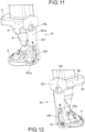
figures 11 and 12 are perspective views from respective sides of a portion of a first part of a core or internal component of a mold according to the present invention, -
figures 13 and 14 show the inside of two external shells of a mold according to the present invention. - In the attached drawings, identical parts or components are identified by the same reference numbers.
- The present invention relates to a
mold 1 for the production, in particular for injection or vulcanization moulding, of an outer shell of a ski boot, comprising a core orinternal component 2 having amolding portion 3 and aconstraint portion 4, the mold further including at least twoexternal shells - The mold then comprises means for approaching/removing the
external shells - at least one closed position (see
figure 1 ), in which theexternal shells entire molding portion 3 and at least part of theconstraint portion 4 of the core orinternal component 2, in such a way as to engage theconstraint portion 4 and define with anexternal surface 3a of themolding portion 3 a gap or impression for molding a compound or mixture, for example a polymeric material or other suitable material to obtain an outer shell of a ski boot, and - at least one opening or removing position (see
figure 1 ), in which it is possible to decouple from the core orinternal component 2 an outer shell molded in the molding gap or impression. - The gap or molding impression has any suitable width, for example between 0.1 mm and 1 cm or even different, depending on the thickness of an outer shell of a ski boot.
- The means of approaching/removing can comprise one or more electric, hydraulic or oleodynamic actuators and can be used to move one or more of the
outer shells internal component 2. - As regards in detail the
molding portion 3, it has anexternal surface 3a configured as the inside of an outer shell of a ski boot, and then has aback 3b, a tip orfront 3c, atop 3d, abottom 3e andsides molding portion 3 and in the gap or impression. - Thus, for example, the
bottom 3e could be substantially flat or even with a configuration having a step to simulate the bottom of a boot with a heel protruding downwards. - The top 3d could be flat or follow a curved path, if desired with a lower section or section closer to the bottom on the back and a higher section or section further from the bottom on the front or tip.
- A section could also be provided, in a plane orthogonal to the
back 3b-front 3c direction, tapered as it approaches the tip orfront 3c. - The
molding portion 3 approaching theconstraint portion 4 could have a section, in a plane orthogonal to the top 3d-bottom 3e direction, first decreasing and then increasing with a substantially flared external surface, this last part of the section corresponding to the upper part of an external shell of a ski boot. - The
constraint portion 4 instead has, moving away from themolding portion 3, at least one section of continuation of the shape of themolding portion 3 or at least one section of connection or intermediate 8 and then at least one section protruding or recessed 9 with respect to the section of continuation of the shape or connection orintermediate section 8. - Moreover, the core or
internal component 2 comprises at least two mutually movable parts (hereinafter also referred to as "movable parts") 10, 11 or movable with respect to each other, that is to say at least one first 10 and one second 11 part. To better explain, themolding portion 3 and theconstraint portion 4 each have a section or segment or sector belonging to thefirst part 10 and each a section or segment or sector belonging to thesecond part 11. - More in detail, the two
parts - a molding position (see
figures 3 ,5 and7 ), in which the external faces of the at least two mutuallymovable parts external surface 3a configured as the inside of an outer shell of a ski boot to be molded, and - a position of extraction or disinsertion from the core or
internal component 2 of an outer shell molded into the molding gap or impression GI. - In the position of extraction or disinsertion, the two
parts - The
second part 11 extends 3h on theback 3b of themoulding portion 3 from thebottom 3e to thetop 3d (with reference to the moulding position) of the latter and continues 8a then in the at least one section of continuation of the shape or connection or intermediate 8, ending 9a in at least part of the at least one protruding or recessedsection 9. - The
second part 11 then comprises a segment orsector 3h of themoulding portion 3, a segment orsector 8a of the section of continuation of the shape or connection or intermediate 8 and a segment orsector 9a of the at least one protruding or recessedsection 9. - The
second part 11 is advantageously in a single piece or unique piece, being for example, by way of example and not as a limitation, made of steel or other suitable material. - The
first part 10 comprises the other parts of themolding portion 3 and theconstraint portion 4. Thefirst part 10 is preferably in a single piece or enbloc, being for example, purely indicative and not limitative, made of aluminum or other suitable material, although a movable tip could be provided or in any case a tip configured for example as described in the European patentEP3326483B1 could be provided. - It is also noted that at least one or, preferably two or more of the
external shells recessed portion 9, preferably a sector orpiece 9a of the same belonging to thesecond part 11 and, if desired, also a portion of the same belonging to thefirst part 10. - This engagement ensures, alone or with other arrangements or configurations of the components of the mold, among other things the removable locking of the
mobile parts parts - Preferably, at least one or, preferably two or more of the
external shells piece 8a of the same belonging to thesecond part 11 and/or a portion of the same belonging to thefirst part 10. - This engagement also contributes to the removable locking of the
movable parts parts - Advantageously, the mutually
movable parts pivot pin 12, so that thesecond part 11 is movable with respect to the other 10 or other parts according to a curved or curvilinear direction around thepivot pin 12. Thepivot pin 12 is preferably arranged in a direction parallel to the direction from oneside 3f to the other 3g of themolding portion 3. - With reference to this aspect, the
second part 11 may comprise a protruding fin orwall 11c (seefigures 9 and12 ) towards the inside of themolding portion 3, which is designed to be inserted, preferably loosely, into a groove GR delimited by thefirst part 10. In this case, thepivot pin 12 is inserted or fitted in a through hole or opening 11d delimited in the protruding fin orwall 11c and in one or more holes oropenings 10a, if desired through, which is or are delimited in thefirst part 10 and which is or are aligned with the hole or opening 11d. - Clearly, the groove GR must have a configuration such as to allow the protruding fin or
wall 11c to move inside it during the mutual movement of thefirst part 10 andsecond part 11. - Of course, a fin could also be provided in the
first part 10 to be engaged in a groove of thesecond part 11 or another configuration for the pivoting engagement between the mutually movable parts. - The
pivot pin 12 is advantageously provided housed in themolding portion 3, for example at theback 3b of themolding portion 3 at an intermediate level between thebottom 3e and thetop 3d of the same. - If desired, the interface or coupling surface IS1, IS2 (not considering any fin and groove described above) of each of the at least two mutually
movable parts others parts front 3c, at themolding portion 3 and then in the constraint portion 4 a substantially rectilinear section IS1b, IS2b or in any case with a direction, in the molding position, of main extension substantially parallel to the direction from thetop 3d to thebottom 3e. In this case, the substantially rectilinear section IS1b, IS2b could also extend in part, at an initial segment or segment of connection with the curved or curvilinear segment IS1a, IS2a, in the molding portion 3 (seefigures 9 to 12 ). - The interface or coupling surfaces IS1, IS2 or rather the zone between them reaches or is open towards the
sides molding portion 3. Preferably, the interface or coupling surfaces IS1, IS2 or rather the zone between them also opens, upwards in the figures, at the protruding or recessedsection 9. - The at least one protruding or recessed
section 9 can be, for example, protruding in the rear 3b-front 3c direction with respect to the section of continuation of the shape or connection orintermediate section 8, or even with a larger section, if desired between 1.1 and 5 times, if desired between 2 and 3 times, than the latter in a plane orthogonal to thebottom 3e-top 3d direction. - According to the non-limiting embodiment illustrated in the figures, the protruding
section 9 is configured substantially as a strip or polyhedron in the molding position, while thesecond part 11 comprises asegment 9a, in particular an end segment, of the strip or polyhedron, so that in the extraction or disinsertion position, thesegment 9a of the strip or polyhedron is misaligned or in any case staggered or shifted with respect to the remainingportion 9b of the strip or polyhedron. - Advantageously, the protruding or recessed
section 9 is configured substantially as a polyhedron with a main dimension greater than the others in a direction parallel to the front 3c-back 3b direction. - Even more advantageously, the protruding or recessed
section 9 is configured as a parallelepiped or prism, if desired with hexagonal bases, while thesecond part 11 comprises afirst segment 9a of the protruding or recessedsection 9 protruding with respect to the section of continuation of the shape or of connection or intermediate 8 in the front 3c-back 3b direction and with direction starting from the section of continuation of the shape or of connection or intermediate from the front 3c to theback 3b. Thefirst segment 9a can be engaged, by means of a fitting or a shape or contact engagement, in whole or in part, in the closed position in part of a recessed zone or shape S1, S2 (seefigures 13 and 14 ) delimited by one or both or more of theexternal shells - With reference instead to the remaining
portion 9b of the protruding or recessedsection 9, which belongs to thefirst part 10, it could also include asecond segment 9c of the protruding or recessed section protruding with respect to the section of continuation of the shape or connection or intermediate 8 in the direction from the front 3c-back 3b and with direction starting from the section of continuation of the shape or connection or intermediate from the back 3b to the front 3b. - In essence, the protruding or recessed
section 9 could include a segment orsector 9a protruding towards the back with respect to the section of continuation of the shape or connection or intermediate 8 or two 9a, 9c segments protruding one towards the back and the other towards the front with respect to the section of continuation of the shape or connection or intermediate 8. - Alternatively, the protruding or recessed
section 9 could comprise one or more recesses or hollow areas that can be engaged, by means of a shape fitting or engagement or engagement by contact, in whole or in part, in the closed position by a respective raised area of one or both or more of theexternal shells - If desired, the
second part 11 comprises a reinforcing segment orgusset 11a that extends between arespective segment 8a in the at least one segment of continuation of the shape or of connection or intermediate 8 and arespective segment 9a in the at least one protruding or recessedsection 9. - With specific reference now to the segment of continuation of the shape or of connection or intermediate 8, it could have any suitable configuration. According to the non-limiting embodiment illustrated in the figures, it constitutes the continuation of the shape of the
molding portion 3, that is to say that the section, in a plane orthogonal to the top 3d-bottom 3e direction, of theconstraint portion 4 moving away from themoulding portion 3, is increasing with a substantially flared external surface. - Furthermore, one or more relief or recessed
areas 14 may be provided on one or both of the interface or coupling surfaces IS2, IS1, such area orareas 14 being provided to reduce the contact area between theparts - The
mold 1 may then comprise interference or mechanical engagement means 13a, 13b (seefigures 10 ,11 and 12 ) of the at least two mutuallymovable parts - According to the non-limiting embodiment illustrated in the figures, the possible means of interference or mechanical engagement comprise at least one
projection 13a in the first 10 or second 11 part which is wholly or partly partially conical or tapered moving away from the respective first 10 or second 11 part or better from a respective interface or coupling surface IS1, IS2, the at least oneprojection 13a being designed to engage, in the molding position, arespective seat 13b in the other second 11 or first 10 part starting from a respective interface or coupling surface IS2, IS1, whichseat 13b is partially conical or with a section decreasing towards the inside of the respective second 11 or first 10 part. - The engagement in the closed position, between the
projection 13a and theseat 13b could be by shape or contact along the entire surface of theprojection 13a or even only at part of this surface, in which case, in the closed position, non-contact or non-interference zones would be provided. - If desired, the
mold 1 comprises at least one elastic loading element 15 (shown for clarity of positioning both infigures 9 and 10 , and infigures 11 and 12 ), such as for example a spring or the like, designed to oppose the relative movement of the mutuallymovable parts movable parts - The at least one
elastic loading element 15 is designed to bring the at least twomovable parts movable parts external shells section 9 or with a respective segment orsector 9a. - The
elastic loading element 15, such as a spring, for example a helical spring, has one end or section constrained or connected or integral with thefirst part 10 and another end or section constrained or connected or integral with thesecond part 11. With reference to the non-limiting embodiment illustrated in the figures, thespring 15 has one end or section constrained or connected or integral within the groove GR delimited by thefirst part 10 and another end or section constrained or connected or integral with the protruding fin orwall 11c of thesecond part 11. - The
mold 1 can or cannot include actuators for moving the at least twomovable parts - If such an actuator is provided, it is preferably designed to act directly or by means of a respective lever or pusher component against the back of the
second part 11. Clearly, such an actuator could act in proximity to theexternal shells internal component 2 is brought after molding and after the opening or removal of theexternal shells - According to the non-limiting embodiment illustrated in the figures, the
mold 1 further comprises abeam component 16 for moving the core orinternal component 2 when theshells constraint portion 4 comprises aconnection section 17 to thebeam component 16, while theconnection section 17 extends from the at least one protruding or recessedsection 9 away from themolding portion 3. - Clearly, the
beam component 16 can be moved in any suitable way, by means of appropriate actuator means, to move the core orinternal component 2 depending on the step of the molding method. - With reference then in detail to the
external shells main shells main face main face internal component 2, and more specifically of the molding portion 3 (taking into account the thickness of the moulding gap or impression) and of part of theconstraint portion 4, also taking into account the gap or moulding impression and any localized slack, for example in the section of continuation of the shape or connection orintermediate section 8 and/or in the protruding or recessedsection 9 and/or in theconnection section 17. - The two shapes S1, S2 advantageously have a substantially mirrored configuration.
- Moreover, one or, preferably, both shapes S1, S2 have at least:
- a first portion S3, S4 configured substantially as the external surface of the
molding portion 3, clearly also taking into account the thickness of the molding gap or impression that must be maintained between theexternal shells molding portion 3, and - a second portion S5, S6 configured substantially as the external surface of the at least one protruding or recessed
section 9 or at least defining, among other things, one or more specific recessed or protruding areas or portions S5a, S6a for engagement, by fitting or interlocking or by shape or in contact, with at least one first protruding segment orsector 9a of the same or with one or more recesses or hollow areas defined in the protruding or recessedsection 9. - Substantially, the second portion S5, S6 is substantially complementary to at least one protruding or recessed
section 9 or at least with at least one first protruding segment orsector 9a or with one or more recesses or hollow zones of the protruding or recessedsection 9. - If desired, one or, preferably, both of the shapes S1, S2 also have a third portion S7, S8 configured substantially, in whole or in part as the external surface of the at least one continuation section of the shape or connection or
intermediate section 8, so as to ensure an engagement, if desired of contact or shape, between portion S7, S8 and all or part of thesection 8. - Moreover, if the core or
internal component 2 comprises a connecting section 18, then one or, preferably, both of the shapes S1, S2 can also include a fourth portion S9, S10 configured substantially as the external surface of the connectingsection 17, so as to ensure an engagement, if desired of contact or shape, between portion S9, S10 and all or part of thesection 17. - Clearly, when the two
external shells external shells internal component 2. - This entails in detail that the two first portions S3, S4 are actually joined or rather faced against each other with the interposition of the
moulding portion 3, leaving the molding gap or impression, while the two second portions S5, S6 are in fact joined or rather faced against each other with the interposition of the protruding or recessedsection 9 which is tightened between them, at least as a function of the shape engagement or interlocking or fitting or contact engagement of part of one or both of the second portions S5, S6 with at least one first protruding segment orsector 9a or with one or more recesses or hollow zones of the protruding or recessedsection 9, although preferably the interlocking or fitting or shape engagement involves the entire protruding or recessedsection 9. - If desired, in the closed position, the two third portions S7, S8 are in fact joined or better faced each other with the interposition of the continuation section of the shape or connection or intermediate 8, which is tightened, in whole or in part, between them.
- Moreover, if the core or
internal component 2 includes a connection section 18, then in the closed position, the two fourth portions S9, S10 are in fact joined or better faced each other with the interposition of theconnection section 17, which is tightened, in whole or in part, between them. - If desired, the external shells also comprise a
bottom plate 7 designed to be placed under the core orinternal component 2, in contact with the bottom of the latter in the closed position and defining with the latter part of the molding gap or impression, in particular the part designed to constitute, once the compound or mixture has been moulded, the bottom of an outer shell of a ski boot. - The
bottom plate 7 can be housed, at least in the molding position, in special fifth portions S11,S 12 of one or both of the shapes S1, S2. - Clearly, the
mold 1 also comprises other components or elements, such as definition components mounted slidingly or not and designed to define respective decorations or configurations on an outer shell to be moulded. - In the mold or better in the external shells can then be delimited the paths for the possible injection of the compound or mixture into the gap or impression as well as other possible elements of a mold for the production, in particular for injection or vulcanization molding, of an external shell of a ski boot.
- Of course, a machine according to the present invention could comprise a series of
molds 1 each mounted around a respective frame. - A method for molding, in particular for injection or vulcanization molding, an outer shell of a ski boot using a mold as above indicated substantially comprises the following steps:
- arrange the
external shells - relatively move the core or
internal component 2 and theexternal shells internal component 2 is in a zone between theexternal shells - with the core or
internal component 2 in the molding position or close to it, activate the approach/removal means so as to bring theexternal shells entire molding portion 3 and at least part or all of theconstraint portion 4 and engage at least part of theconstraint portion 4 defining with theexternal surface 3a of themolding portion 3 a gap or impression for molding a compound or mixture for obtaining an outer shell of a ski boot, - inject a compound or mixture into the gap or impression after the previous step or arrange a compound or mixture on the core or
internal component 2 in the molding position before moving theexternal shells - molding, if desired by applying heat or pressure or with other suitable means, the outer shell in the gap or impression with the
external shells - bringing the
external shells internal component 2 the outer shell molded in the molding gap or impression following the movement of the mutuallymovable parts - Furthermore, at least one of the
external shells section 9 and, if desired, also the at least one section of continuation of the shape or of connection orintermediate section 8. - Preferably, the completion of the movement of the mutually
movable parts movable parts external shells section 9. - If an
elastic loading element 15 is provided, the same would be designed to bring the at least twomovable parts movable parts external shells section 9. - Clearly, an
elastic loading element 15 could also not be provided, but could be provided an actuator or similar to relatively move the twoparts - With reference to the step of decoupling from the core or internal component, the outer shell molded in the molding gap or impression following the movement of the mutually
movable parts molding portion 3, in particular from the section of themolding portion 3 belonging to the fixedpart 10, after which it is possible, by appropriately pushing the outer shell, to complete the removal or decoupling. - In this regard, the decoupling step can be carried out by pushing, using a special actuator, for example pneumatic or hydraulic or oleodynamic or even manually or using a special lever, preferably at the outside of the heel of the external shell.
- Furthermore, once the
external shells internal component 2 can be moved, acting on thepossible beam component 16, so as to bring it to a zone where the decoupling or removal of the outer shell from the core orinternal component 2 occurs. - As it will be understood thanks to a
mold 1 and a method according to the present invention, it is possible to free or remove the external shell of a ski boot from a core orinternal component 2 of a mold without damaging the outer shell. - Furthermore, the closing and confirmation of the closure system of the
mold 1 is carried out with very simple and effective mechanics, actually obtained with a mechanical torque on metal parts. - A resistant coupling is thus obtained during the molding step, thanks to the engagement between at least one
external shell section 9 in the closed position. This ensures mold resistance and durability, even in the face of high specific pressures during molding. - Therefore, large interference surfaces between the shells and the internal core are provided, as well as the safety of the mutual position between the first 10 and second 11 parts during molding and, if desired, when the material is inserted.
- Modifications and variants of the invention are possible with the scope defined by the claims.
Claims (18)
- Mold for the production, in particular for injection or vulcanization moulding, of an outer shell of a ski boot, comprising:- a core or internal component (2) having a molding portion (3) and a constraint portion (4),- at least two external shells (5, 6, 7), e- means for approaching/removing said at least two external shells (5, 6, 7), betweenat least one closed position, in which said at least two external shells (5, 6, 7) surround the entire molding portion (3) and at least part of said constraint portion (4) of said core or internal component (2), in such a way as to engage said constraint portion (4) and define with an external surface (3a) of said molding portion (3) a gap or impression (GI) for molding a compound or mixture to obtain an outer shell of a ski boot, andat least one opening or removing position, in which it is possible to decouple from said core or internal component (2) an outer shell molded in said molding gap or impression (GI),said molding portion (3) having an external surface (3a) configured as the inside of an outer shell of a ski boot, and thus having a back (3b), a tip or front (3c), a top (3d), a bottom (3e) and sides (3f, 3g) corresponding, respectively, to the internal surface of the back, toe, top, bottom and sides of an outer shell of a ski boot to be molded on said molding portion (3), whereassaid constraint portion (4) has, moving away from said molding portion (3), at least one continuation section of the shape of said molding portion (3) or at least one connecting or intermediate section (8) and then at least one section (9) protruding or recessed with respect to the continuation section of the shape or connecting or intermediate section (8),said core or internal component (3) comprising at least two parts (10, 11) mutually movable with respect to each other, i.e. at least one first (10) and one second (11) part, said at least two parts (10, 11) being mutually movable betweena molding position, in which the external faces of said at least two mutually movable parts (10, 11) are aligned or in any case arranged so as to define the external surface (3a) configured as the inside of an outer shell of a ski boot to be molded, anda position of extraction or disinsertion from the core or internal component (2) of an outer shell molded into said molding gap or impression (GI),wherein said second part (11) extends on the back (3b) of the molding portion (3) from the bottom (3e) to the top (3d) of the latter and then continues in said at least one continuation section of the shape or connecting or intermediate section (8), terminating in at least part (9a) of said at least one protruding or recessed section (9), andwherein at least one of said at least two external shells (5, 6, 7) in said closed position engages, in whole or in part, said at least one protruding or recessed section (9).
- Mold according to claim 1, wherein at least one of said at least two external shells (5, 6, 7) in said closed position, fit engages or engages by shape in whole or in part, said at least one protruding or recessed section (9).
- Mold according to claim 1 or 2, wherein in said closed position at least one of said at least two external shells (5, 6, 7) also engages said at least one continuation section of the shape or connecting or intermediate section (8).
- Mold according to claim 1 or 2 or 3, wherein said mutually movable parts (10, 11) are pivoted to each other around a pivot pin (12), so that said second part (11) is movable with respect to the other part or parts (10) in a curved or curvilinear direction around the pivot pin (12).
- Mold according to any one of the previous claims, wherein the interface or coupling surface (IS1, IS2) of each of said at least two mutually movable parts (10, 11) with the other or others mutually movable parts (11, 10) has a curved or curvilinear segment (IS1a, IS2a) at the molding portion (3) and then, in the constraint portion (4), a substantially straight section (IS1b, IS2b) or in any case a section, in the molding position, with a main extension direction substantially parallel to the direction from the top (3d) to the bottom (3e).
- Mold according to any one of the previous claims, wherein said at least one protruding or recessed section (9) protrudes, in the rear (3b)-front (3c) direction, with respect to said continuation section of the shape or connecting or intermediate section (8) or a section larger than the latter in a plane orthogonal to the bottom (3e)-top (3d) direction, said protruding section (9) being substantially shaped as a slat or a polyhedron in said molding position, said second part (11) including a segment (9a) of said slat or polyhedron, so that in said extraction or disinsertion position the segment (9a) of the slat or polyhedron is misaligned or in any case staggered or displaced with respect to the remaining part (9b) of the slat or polyhedron.
- Mold according to claim 6, wherein said at least one protruding or recessed section (9) is substantially shaped as a polyhedron with a main dimension larger than the others in a direction parallel to the front (3c)-back (3b) direction.
- Mold according to claim 6 or 7, wherein said at least one protruding or recessed section (9) is shaped as a parallelepiped or prism, if desired with hexagonal bases, while said second part (11) includes a segment (9a) of said at least one protruding or recessed section (9) protruding with respect to said at least one continuation section of the shape or connecting or intermediate section (8) in the front (3c)-rear (3b) direction and starting from said continuation section of the shape or connecting or intermediate section (8) with a direction from the front (3c) to the back (3b).
- Mold according to any one of the previous claims, wherein said second part (11) includes a reinforcement segment or gusset (11a) which extends between a respective segment (8a) of said at least one said continuation section of the shape or connecting or intermediate section (8) and a respective segment (9a) of said at least one protruding or recessed section (9).
- Mold according to any one of the previous claims, comprising mechanical interference or engagement means (13a, 13b) of said at least two mutually movable parts (10, 11) formed at the respective interface or coupling surfaces (IS1, IS2) of said at least two mutually movable parts (10, 11) with each other or with the others.
- Mold according to claim 10, wherein said mechanical interference or engagement means comprise at least one projection (13a) in said first (10) or second (11) part which is wholly or partly conical or tapered away from the respective first (10) or second part (11), said at least one projection (13a) being designed to engage, in said molding position, a respective seat (13b) in the other second (11) or first (10) part, which seat (13b) is partially conical or with a section decreasing towards the inside of the respective second (11) or first (10) part.
- Mold according to any one of the previous claims, comprising at least one elastic loading element (15) designed to oppose the relative movement of said at least two mutually mobile parts (10, 11) from said molding position to said extraction or disinsertion position and designed to act so as to bring said at least two mutually movable parts (10, 11) back into or towards said molding position.
- Mold according to claim 12, wherein said at least one elastic loading element (15) is designed to bring said at least two mutually movable parts (10, 11) towards said molding position or close to the same, but the completion of the movement from said extraction or disinsertion position to said molding position or in any case the removable locking of said mutually movable parts (10, 11) in said molding position is carried out by the engagement of at least one of said at least two external shells (5, 6, 7) with said at least one protruding or recessed section (9) or with a segment or sector (9a) thereof.
- Mold according to any one of the previous claims, wherein said mold includes at least one actuator for moving said at least two mutually movable parts (10, 11) with respect to each other.
- Mold according to claim 14, wherein said at least one actuator is designed to act directly or by means of a respective lever or pusher component against the back of said second part (11).
- Mold according to any one of the previous claims, comprising a beam component (16) for moving said core or internal component (2) when said at least two shells (5, 6, 7) are in said at least one opening or removing position and wherein said constraint portion (4) includes a connection section (17) to said beam component (16), said connection section (17) extending from said at least one protruding or recessed section (9) away from said molding portion (3).
- Method for molding, in particular for injection or vulcanization molding, an outer shell of a ski boot using a mold according to any one of the preceding claims, said method comprising the following steps:- arrange said external shells (5, 6, 7) in said at least one opening or removal position,- relatively move said core or internal component (2) and said external shells (5, 6, 7), so that said core or internal component (2) is in an area between said external shells (5, 6, 7),- with said core or internal component in said molding position or close to it, activate the approach/removal means so as to bring said at least two external shells (5, 6, 7) in said at least one closed position, so that said at least two external shells (5, 6, 7) surround the entire molding portion (3) and at least part of said constraint portion (4) of said core or internal component (2) and engage at least part of said constraint portion (4) defining with said external surface (3a) of said molding portion (3) a gap or impression (GI) for molding a compound or mixture for obtaining an outer shell of a ski boot,- inject a compound or mixture into said gap or impression (GI) after the previous step or arrange a compound or mixture on said core or internal component (2) in said molding position before moving said external shells (5, 6, 7) to said closed position,- molding said outer shell in said gap or impression (GI) with said external shells (5, 6, 7) in said at least one closed position,- bring said external shells (5, 6, 7) into said at least one opening or removing position and decouple from said core or internal component (2) the outer shell molded in said molding gap or impression (GI) following the movement of said mutually movable parts (10, 11) to said extraction or disinsertion position,wherein at least one of the external shells (5, 6, 7) engages, in whole or in part, said at least one protruding or recessed section (9) in said closed position.
- Method according to claim 17, wherein the completion of the movement of said mutually movable parts (10, 11) from said extraction or disinsertion position to said molding position or in any case the removable locking of said mutually movable parts (10, 11) in said molding position is carried out also or only by engaging at least one of the external shells (5, 6, 7) with said at least one protruding or recessed section (9).
Priority Applications (1)
| Application Number | Priority Date | Filing Date | Title |
|---|---|---|---|
| SI202430029T SI4530056T1 (en) | 2023-09-28 | 2024-09-27 | MOULD FOR MANUFACTURING, ESPECIALLY FOR INJECTION OR VULCANIZATION, THE OUTER LAYER OF A SKI BOOT |
Applications Claiming Priority (1)
| Application Number | Priority Date | Filing Date | Title |
|---|---|---|---|
| IT102023000020028A IT202300020028A1 (en) | 2023-09-28 | 2023-09-28 | MOLD FOR THE PRODUCTION, IN PARTICULAR BY INJECTION MOULDING OR VULCANIZATION, OF AN EXTERNAL SHELL OF A SKI BOOT AND RELATED METHOD. |
Publications (2)
| Publication Number | Publication Date |
|---|---|
| EP4530056A1 true EP4530056A1 (en) | 2025-04-02 |
| EP4530056B1 EP4530056B1 (en) | 2026-02-11 |
Family
ID=89158302
Family Applications (1)
| Application Number | Title | Priority Date | Filing Date |
|---|---|---|---|
| EP24203293.6A Active EP4530056B1 (en) | 2023-09-28 | 2024-09-27 | Mold for the production, in particular for injection or vulcanization moulding, of an outer shell of a ski boot |
Country Status (3)
| Country | Link |
|---|---|
| EP (1) | EP4530056B1 (en) |
| IT (1) | IT202300020028A1 (en) |
| SI (1) | SI4530056T1 (en) |
Citations (3)
| Publication number | Priority date | Publication date | Assignee | Title |
|---|---|---|---|---|
| DE1950826A1 (en) | 1969-10-09 | 1971-04-15 | Desma Werke Gmbh | Extruded and vulcanised footwear |
| IT201700099963A1 (en) | 2017-09-06 | 2019-03-06 | Lismec Srl | Mold for the production of a sports shoe or part of it and a method for producing a sports shoe or part of it using said mold |
| EP3326483B1 (en) | 2016-11-24 | 2019-06-19 | Fmb S.R.L. | Last for obtaining a shell of a boot provided with a rigid sole |
-
2023
- 2023-09-28 IT IT102023000020028A patent/IT202300020028A1/en unknown
-
2024
- 2024-09-27 EP EP24203293.6A patent/EP4530056B1/en active Active
- 2024-09-27 SI SI202430029T patent/SI4530056T1/en unknown
Patent Citations (3)
| Publication number | Priority date | Publication date | Assignee | Title |
|---|---|---|---|---|
| DE1950826A1 (en) | 1969-10-09 | 1971-04-15 | Desma Werke Gmbh | Extruded and vulcanised footwear |
| EP3326483B1 (en) | 2016-11-24 | 2019-06-19 | Fmb S.R.L. | Last for obtaining a shell of a boot provided with a rigid sole |
| IT201700099963A1 (en) | 2017-09-06 | 2019-03-06 | Lismec Srl | Mold for the production of a sports shoe or part of it and a method for producing a sports shoe or part of it using said mold |
Also Published As
| Publication number | Publication date |
|---|---|
| IT202300020028A1 (en) | 2025-03-28 |
| SI4530056T1 (en) | 2026-06-30 |
| EP4530056B1 (en) | 2026-02-11 |
Similar Documents
| Publication | Publication Date | Title |
|---|---|---|
| EP4530056B1 (en) | Mold for the production, in particular for injection or vulcanization moulding, of an outer shell of a ski boot | |
| CN115320044B (en) | Locking mechanism of mold, mold and method of using the locking mechanism | |
| EP0825007A1 (en) | Mold assembly for making multilayer molded article and method of making multilayer molded article using the same | |
| MXPA05003552A (en) | Method and apparatus for die-casting a v-block for an internal combustion engine. | |
| CN104690911A (en) | Injection mold of composite core-pulling mechanism | |
| US20120177774A1 (en) | Ejector retraction mechanism | |
| KR102011905B1 (en) | Injection mold for diversifying embo pattern | |
| US4778368A (en) | Device for the production of boots having portions of different colors | |
| JP5270977B2 (en) | Mold | |
| JP7682141B2 (en) | Weather strip mold equipment | |
| JP3966028B2 (en) | Injection mold and injection molding method | |
| US3838956A (en) | Device for molding a sole onto a shoe upper | |
| US20110280985A1 (en) | Ejector retraction mechanism | |
| CN217047147U (en) | Die sinking structure of sole compression molding mould | |
| TWM653167U (en) | Shoe mold device | |
| JP2007296773A (en) | Slide core device for multicolor molding | |
| EP4017311B1 (en) | A footwear injection mould | |
| CN2155700Y (en) | Shoe midsole forming mold | |
| JP3035655B2 (en) | Gate cutting method in mold equipment | |
| AU2003204005B2 (en) | A last locking device | |
| EP2206442B1 (en) | Process for manufacturing a work shoe | |
| KR200387700Y1 (en) | Mold for Shoes | |
| CN217803027U (en) | Finished shoe injection mold | |
| CN219381424U (en) | Forming die of full-plastic faucet | |
| CN222346346U (en) | Shoemaking mould |
Legal Events
| Date | Code | Title | Description |
|---|---|---|---|
| PUAI | Public reference made under article 153(3) epc to a published international application that has entered the european phase |
Free format text: ORIGINAL CODE: 0009012 |
|
| STAA | Information on the status of an ep patent application or granted ep patent |
Free format text: STATUS: THE APPLICATION HAS BEEN PUBLISHED |
|
| AK | Designated contracting states |
Kind code of ref document: A1 Designated state(s): AL AT BE BG CH CY CZ DE DK EE ES FI FR GB GR HR HU IE IS IT LI LT LU LV MC ME MK MT NL NO PL PT RO RS SE SI SK SM TR |
|
| P01 | Opt-out of the competence of the unified patent court (upc) registered |
Free format text: CASE NUMBER: APP_24615/2025 Effective date: 20250522 |
|
| STAA | Information on the status of an ep patent application or granted ep patent |
Free format text: STATUS: REQUEST FOR EXAMINATION WAS MADE |
|
| GRAP | Despatch of communication of intention to grant a patent |
Free format text: ORIGINAL CODE: EPIDOSNIGR1 |
|
| STAA | Information on the status of an ep patent application or granted ep patent |
Free format text: STATUS: GRANT OF PATENT IS INTENDED |
|
| 17P | Request for examination filed |
Effective date: 20250731 |
|
| INTG | Intention to grant announced |
Effective date: 20250901 |
|
| GRAS | Grant fee paid |
Free format text: ORIGINAL CODE: EPIDOSNIGR3 |
|
| GRAA | (expected) grant |
Free format text: ORIGINAL CODE: 0009210 |
|
| STAA | Information on the status of an ep patent application or granted ep patent |
Free format text: STATUS: THE PATENT HAS BEEN GRANTED |
|
| AK | Designated contracting states |
Kind code of ref document: B1 Designated state(s): AL AT BE BG CH CY CZ DE DK EE ES FI FR GB GR HR HU IE IS IT LI LT LU LV MC ME MK MT NL NO PL PT RO RS SE SI SK SM TR |
|
| REG | Reference to a national code |
Ref country code: CH Ref legal event code: F10 Free format text: ST27 STATUS EVENT CODE: U-0-0-F10-F00 (AS PROVIDED BY THE NATIONAL OFFICE) Effective date: 20260211 Ref country code: GB Ref legal event code: FG4D |
|
| REG | Reference to a national code |
Ref country code: DE Ref legal event code: R096 Ref document number: 602024002515 Country of ref document: DE |
|
| REG | Reference to a national code |
Ref country code: IE Ref legal event code: FG4D |
|
| REG | Reference to a national code |
Ref country code: NL Ref legal event code: MP Effective date: 20260211 |
|
| PG25 | Lapsed in a contracting state [announced via postgrant information from national office to epo] |
Ref country code: RS Free format text: LAPSE BECAUSE OF FAILURE TO SUBMIT A TRANSLATION OF THE DESCRIPTION OR TO PAY THE FEE WITHIN THE PRESCRIBED TIME-LIMIT Effective date: 20260511 |
|
| PG25 | Lapsed in a contracting state [announced via postgrant information from national office to epo] |
Ref country code: ES Free format text: LAPSE BECAUSE OF FAILURE TO SUBMIT A TRANSLATION OF THE DESCRIPTION OR TO PAY THE FEE WITHIN THE PRESCRIBED TIME-LIMIT Effective date: 20260211 |
|
| PG25 | Lapsed in a contracting state [announced via postgrant information from national office to epo] |
Ref country code: PL Free format text: LAPSE BECAUSE OF FAILURE TO SUBMIT A TRANSLATION OF THE DESCRIPTION OR TO PAY THE FEE WITHIN THE PRESCRIBED TIME-LIMIT Effective date: 20260211 |
|
| PG25 | Lapsed in a contracting state [announced via postgrant information from national office to epo] |
Ref country code: GR Free format text: LAPSE BECAUSE OF FAILURE TO SUBMIT A TRANSLATION OF THE DESCRIPTION OR TO PAY THE FEE WITHIN THE PRESCRIBED TIME-LIMIT Effective date: 20260512 |
|
| REG | Reference to a national code |
Ref country code: LT Ref legal event code: MG9D |
|
| PG25 | Lapsed in a contracting state [announced via postgrant information from national office to epo] |
Ref country code: LT Free format text: LAPSE BECAUSE OF FAILURE TO SUBMIT A TRANSLATION OF THE DESCRIPTION OR TO PAY THE FEE WITHIN THE PRESCRIBED TIME-LIMIT Effective date: 20260211 |
|
| PG25 | Lapsed in a contracting state [announced via postgrant information from national office to epo] |
Ref country code: NO Free format text: LAPSE BECAUSE OF FAILURE TO SUBMIT A TRANSLATION OF THE DESCRIPTION OR TO PAY THE FEE WITHIN THE PRESCRIBED TIME-LIMIT Effective date: 20260511 |
|
| PG25 | Lapsed in a contracting state [announced via postgrant information from national office to epo] |
Ref country code: SE Free format text: LAPSE BECAUSE OF FAILURE TO SUBMIT A TRANSLATION OF THE DESCRIPTION OR TO PAY THE FEE WITHIN THE PRESCRIBED TIME-LIMIT Effective date: 20260211 Ref country code: FI Free format text: LAPSE BECAUSE OF FAILURE TO SUBMIT A TRANSLATION OF THE DESCRIPTION OR TO PAY THE FEE WITHIN THE PRESCRIBED TIME-LIMIT Effective date: 20260211 |
|
| PG25 | Lapsed in a contracting state [announced via postgrant information from national office to epo] |
Ref country code: HR Free format text: LAPSE BECAUSE OF FAILURE TO SUBMIT A TRANSLATION OF THE DESCRIPTION OR TO PAY THE FEE WITHIN THE PRESCRIBED TIME-LIMIT Effective date: 20260211 |
|
| PG25 | Lapsed in a contracting state [announced via postgrant information from national office to epo] |
Ref country code: IS Free format text: LAPSE BECAUSE OF FAILURE TO SUBMIT A TRANSLATION OF THE DESCRIPTION OR TO PAY THE FEE WITHIN THE PRESCRIBED TIME-LIMIT Effective date: 20260611 Ref country code: PT Free format text: LAPSE BECAUSE OF FAILURE TO SUBMIT A TRANSLATION OF THE DESCRIPTION OR TO PAY THE FEE WITHIN THE PRESCRIBED TIME-LIMIT Effective date: 20260611 |
|
| PG25 | Lapsed in a contracting state [announced via postgrant information from national office to epo] |
Ref country code: NL Free format text: LAPSE BECAUSE OF FAILURE TO SUBMIT A TRANSLATION OF THE DESCRIPTION OR TO PAY THE FEE WITHIN THE PRESCRIBED TIME-LIMIT Effective date: 20260211 |
|
| PG25 | Lapsed in a contracting state [announced via postgrant information from national office to epo] |
Ref country code: LV Free format text: LAPSE BECAUSE OF FAILURE TO SUBMIT A TRANSLATION OF THE DESCRIPTION OR TO PAY THE FEE WITHIN THE PRESCRIBED TIME-LIMIT Effective date: 20260211 |
|
| PG25 | Lapsed in a contracting state [announced via postgrant information from national office to epo] |
Ref country code: BG Free format text: LAPSE BECAUSE OF FAILURE TO SUBMIT A TRANSLATION OF THE DESCRIPTION OR TO PAY THE FEE WITHIN THE PRESCRIBED TIME-LIMIT Effective date: 20260211 |