EP3326483B1 - Last for obtaining a shell of a boot provided with a rigid sole - Google Patents
Last for obtaining a shell of a boot provided with a rigid sole Download PDFInfo
- Publication number
- EP3326483B1 EP3326483B1 EP17202684.1A EP17202684A EP3326483B1 EP 3326483 B1 EP3326483 B1 EP 3326483B1 EP 17202684 A EP17202684 A EP 17202684A EP 3326483 B1 EP3326483 B1 EP 3326483B1
- Authority
- EP
- European Patent Office
- Prior art keywords
- insert
- last
- head
- seats
- main body
- Prior art date
- Legal status (The legal status is an assumption and is not a legal conclusion. Google has not performed a legal analysis and makes no representation as to the accuracy of the status listed.)
- Active
Links
Images






Classifications
-
- A—HUMAN NECESSITIES
- A43—FOOTWEAR
- A43D—MACHINES, TOOLS, EQUIPMENT OR METHODS FOR MANUFACTURING OR REPAIRING FOOTWEAR
- A43D3/00—Lasts
-
- A—HUMAN NECESSITIES
- A43—FOOTWEAR
- A43B—CHARACTERISTIC FEATURES OF FOOTWEAR; PARTS OF FOOTWEAR
- A43B5/00—Footwear for sporting purposes
- A43B5/04—Ski or like boots
-
- A—HUMAN NECESSITIES
- A43—FOOTWEAR
- A43D—MACHINES, TOOLS, EQUIPMENT OR METHODS FOR MANUFACTURING OR REPAIRING FOOTWEAR
- A43D3/00—Lasts
- A43D3/10—Devices for removing lasts
-
- B—PERFORMING OPERATIONS; TRANSPORTING
- B29—WORKING OF PLASTICS; WORKING OF SUBSTANCES IN A PLASTIC STATE IN GENERAL
- B29D—PRODUCING PARTICULAR ARTICLES FROM PLASTICS OR FROM SUBSTANCES IN A PLASTIC STATE
- B29D35/00—Producing footwear
-
- B—PERFORMING OPERATIONS; TRANSPORTING
- B29—WORKING OF PLASTICS; WORKING OF SUBSTANCES IN A PLASTIC STATE IN GENERAL
- B29D—PRODUCING PARTICULAR ARTICLES FROM PLASTICS OR FROM SUBSTANCES IN A PLASTIC STATE
- B29D35/00—Producing footwear
- B29D35/0009—Producing footwear by injection moulding; Apparatus therefor
- B29D35/0018—Moulds
- B29D35/0027—Last constructions; Mountings therefor
Definitions
- the present invention relates to a last for obtaining a shell of a boot provided with a rigid sole.
- alpine ski boots that are constituted by a shell made of plastic material and provided with a rigid sole
- DIN ISO 9523 standard which specifies the dimensions, the characteristics, the requirements, the test methods and the marking of boots with a rigid sole that are used with current ski bindings in the toe region and in the heel region in order to obtain an optimal degree of safety.
- the metal insert in the heel region In order to insert the metal insert in the heel region, it is mounted manually on the molded blank (or shell) by way of fixing with a screw.
- a metal plate which has to be integrated directly onto the shell during molding as an overmolded component.
- This process entails the positioning of the plate, by an operator on board the machine, on the left and right lasts of the mold on which some dedicated centering elements (or cylindrical pins) have been arranged to keep the piece in position during the step of injecting the thermoplastic material.
- US3853446 discloses an apparatus for manufacturing ski-boot shells.
- the aim of the present invention is to eliminate the above mentioned drawbacks in the described known art, by providing a last for obtaining a shell of a boot provided with a rigid sole which can be unseated from the shell rapidly and simply, while at the same time keeping the shell intact and free from deformations during the step of unseating, thus obtaining a high quality and safety of the shell.
- an object of the present invention is to obtain a last that reduces the times for producing and unseating the shell.
- Another object of the invention is to provide a last that reduces the production costs of the shell, by limiting the production of discards.
- Another object is to provide a last that makes it possible to obtain a shell that ensures an optimal and safe coupling with the bindings associated with skis.
- a still further object is to provide an invention that is structurally simple and low cost and which can be made with the usual conventional plants.
- the reference numeral 1, 101 generally designates a last for obtaining a shell 2 of a boot provided with a rigid sole 3 and, in the toe region 4, at least one metal plate 5a, 5b.
- the shell 2 is provided internally, proximate to the toe region 4, with two metal plates 5a, 5b which are arranged mutually side by side, each one with a first hole 6 accessible from inside the shell 2.
- the last 1, 101 has a shape structure that substantially corresponds to that of the inside of the shell 2 of a boot and therefore lacks the toe unit 7 and the heel unit 8.
- Such last 1, 101 is constituted by a main body 9, which reproduces the internal shape structure of the shell 2 except for part of the region 4, which corresponds to the toe of the foot, in which a flat recess 10 is obtained at which an insert 11, 111, which is shaped complementarily to the region 4, is slideably associated.
- the insert 11, 111 is slideable with respect to the main body 9 of the last 1, 101 according to a plane that is inclined by a different angle ⁇ (alpha) to the normal angle ⁇ (beta) of extraction of the shell 2 from the last 1, 101, as shown in Figure 11 .
- the insert 11, 111 has, in a transverse cross-section, a base 12 with a substantially rectangular shape structure from which a first head 13, 113 protrudes axially with a shape structure, in a transverse cross-section, substantially like an upside-down isosceles trapezoid, whereas in plan view the insert 11, 111 has a substantially semicircular shape structure.
- the upper surface 20 of the first head 13 of the insert 11 is flat.
- the upper surface 120 of the first head 113 of the insert 111 is arc-shaped with the concavity facing away from the sole 3.
- the first seats 15a, 15b are adapted to accommodate two complementarily-shaped cylindrical bevel-free first pins 17a, 17b which are slightly longer than the length of the first seats 15a, 15b so that the first pins 17a, 17b, once accommodated in the first seats 15a, 15b, protrude externally and downward from the first lower surface 14 of the insert 11, 111.
- the first pins 17a, 17b are adapted to be positioned and to interact selectively with the first holes 6 of the metal plates 5a, 5b of the shell 2.
- the second seats 18a, 18b are adapted to accommodate two complementarily-shaped cylindrical second pins 19a, 19b, which have the same length as the corresponding second seat 18a, 18b so that the second pins 19a, 19b, once accommodated in the second seats 18a, 18b, are arranged substantially flush with the first lower surface 14 of the insert 11, 111.
- the second pins 19a, 19b are adapted to contribute to the correct positioning of the first pins 17a, 17b in the first seats 15a, 15b, since they constitute an element for abutment against those plates 5a, 5b.
- the first head 13, 113 of the insert 11, 111 is provided stably, at its first upper surface 20, 120 and in a region adjacent to the diameter 16, with a tab or lug 21 that protrudes externally and at right angles to the first head 13, 113.
- the tab 21 has a preferably substantially curved shape structure in plan view.
- the central cavity 23 defines, together with the first upper surface 20, 120 of the first head 13, 113 of the insert 11, 111, a third seat 25 in which a first pintle 26, 126 is positioned.
- the first pintle 26, 126 is substantially T-shaped, a shape adapted to define a second head 27, 127, this second head being adapted to be positioned with one end flush with the front surface 34 of the insert 11, 111 on the opposite side from the tab 21 and to be associated stably with the main body 9 of the last 1, 101, and a first shank 28 which is adapted to extend in the direction of the tab 21.
- the second head 27, 127 of the first pintle 26, 126 has a third lower surface 48, 148 which is shaped substantially complementarily to the corresponding first upper surface 20, 120 of the insert 11, 111.
- the third lower surface 48 of the second head 27 of the first pintle 26 is therefore flat.
- the third lower surface 148 of the second head 127 of the first pintle 126 is therefore curved.
- the second head 27, 127 of the first pintle 26, 126 has a transverse second hole 29 which is adapted to accommodate stably a cylindrical second pintle 30, the ends 31a, 31b of which are accommodated stably in transverse fourth seats 32 that are arranged transversely to the third seat 25 of the main body 9 at the toe region 4.
- the first shank 28 has a length that is less than the distance between the second head 27, 127 and the tab 21 of the insert 11, 111.
- an elastically deformable means 33 such as a cylindrical spring, which has, when inactive, a length that is substantially equal to the distance between the second head 27, 127 and the tab 21 of the insert 11, 111 and therefore a length that is greater than the length of the first shank 28 of the first pintle 26, 126.
- the spring forces the second head 27, 127 and therefore all of the insert 11, 111, so that the front perimetric edge 22 of the main body 9 of the last 1, 101 is arranged flush with the front surface 34 of the insert 11, 111, thus creating a continuity of surfaces in the toe region 4 of the last 1, 101.
- a plate 35a, 35b is associated slideably with each side of the first head 13, 113 of the insert 11, 111.
- Each plate 35a, 35b has substantially the shape structure of a circular segment, so that its outer perimetric edges are arranged flush with the outer perimetric edges 36 of the base 12 of the insert 11, 111, and has a height that is equal to the height of the first head 13, 113 so that their second upper surface 37a, 37b is arranged flush with the first upper surface 20, 120 of the first head 13, 113.
- Each plate 35a, 35b is stably associated with the main body 9 of the last 1, 101 and is adapted to guide the movement of the insert 11, 111 with respect to the main body 9 of the last 1, 101.
- Each plate 35a, 35b has in fact, at its second upper surface 37a, 37b, one or more blind fifth seats 38a, 38b, 38c, 38d, which are substantially T-shaped, each one adapted to stably accommodate the third head 39a, 39b, 39c, 39d and the base of a second shank 40a, 40b, 40c, 40d of a screw 41a, 41b, 41c, 41d which is shaped complementarily thereto, and one or more cylindrical sixth seats 42a, 42b, 42c, 42d, each one adapted to accommodate a third pin 43a, 43b, 43c, 43d which is shaped complementarily thereto.
- the second shanks 40a, 40b, 40c, 40d of the screws 41a, 41b, 41c, 41d and the third pins 43a, 43b, 43c, 43d have a length that is greater than that of the corresponding fifth and sixth seats 38a, 38b, 38c, 38d, 42a, 42b, 42c, 42d.
- the threaded first upper ends 44a, 44b, 44c, 44d of the second shanks 40a, 40b, 40c, 40d and the second upper ends 45a, 45b, 45c, 45d of the third pins 43a, 43b, 43c, 43d are advantageously accommodated stably in seventh and eighth seats 46a, 46b, 47a, 47b, which are provided at the second lower surface 24 of the main body 9 of the last 1, 101.
- the sliding of the main body 9 of the last 1, 101 occurs in a stable and precise manner by virtue of the presence of the plates 35a, 35b, which are stably connected to the main body 9 of the last 1, 101 by virtue of the screws 41a, 41b, 41c, 41d and the third pins 43a, 43b, 43c, 43d, which make it possible to keep to the positional tolerances required by the reference standard in order to ensure the correct operation of alpine ski bindings.
- the elastically deformable means 33 automatically return the insert 11, 111 to its original position inside the third seat 25 and adjacent to the recess 10 of the main body 9 of the last 1, 101, as shown in Figure 11 , thus allowing the extraction of the last 1, 101 from the shell 2 when the last 1, 101 reaches an inclination at an angle ⁇ (beta) that is adapted to allow its complete extraction from the shell 2.
Landscapes
- Engineering & Computer Science (AREA)
- Mechanical Engineering (AREA)
- Health & Medical Sciences (AREA)
- General Health & Medical Sciences (AREA)
- Physical Education & Sports Medicine (AREA)
- Footwear And Its Accessory, Manufacturing Method And Apparatuses (AREA)
Description
- The present invention relates to a last for obtaining a shell of a boot provided with a rigid sole.
- Nowadays, to make alpine ski boots that are constituted by a shell made of plastic material and provided with a rigid sole, it is known to refer to the DIN ISO 9523 standard which specifies the dimensions, the characteristics, the requirements, the test methods and the marking of boots with a rigid sole that are used with current ski bindings in the toe region and in the heel region in order to obtain an optimal degree of safety.
- Within such reference standard, which entails the insertion, both in the toe region and in the heel region, of metal inserts that are adapted to mechanically engage the components of dedicated bindings for this specialism, a specific approach to the construction of the molds has been developed for integrating such fittings in the structure of the shoe.
- In order to insert the metal insert in the heel region, it is mounted manually on the molded blank (or shell) by way of fixing with a screw.
- Differently, for the toe region a metal plate is used which has to be integrated directly onto the shell during molding as an overmolded component.
- This process entails the positioning of the plate, by an operator on board the machine, on the left and right lasts of the mold on which some dedicated centering elements (or cylindrical pins) have been arranged to keep the piece in position during the step of injecting the thermoplastic material.
- One drawback that is found in the known art consists in that the positioning described above creates complications during the step of unseating the molded items from the lasts proper, because the centering elements or the cylindrical pins mechanically hinder the unseating, by rubbing against the seat of the metal plate.
- Further complications affect such drawback when particularly rigid materials, which are typical in making ski boots, are overmolded on the last: such operating step is lengthy and, by virtue of the deformations that can result, gives rise to very costly production discards.
- Furthermore, in some cases it may not be possible to remove the molded items, thus requiring the use of measures that are very costly and not always fruitful.
- In order to seek to overcome the above mentioned drawbacks, it is known to modify the centering pins by beveling one side thereof in order to facilitate their disengagement from the seats of the metal plate during the step of unseating.
- However, this known art also entails drawbacks in that it results in a deterioration of the fixing of the plate, both with regard to the mechanical grip on the last and with regard to precision in the positioning.
- As a consequence, such drawbacks give rise to an acute misalignment between the plate arranged in the toe region and the insert situated in the heel region, such that a correct operation of the binding used to lock the boot to the ski is not ensured, so that the safety of the skier is compromised.
- In other cases, it is found that the plate exits from the seat when the mold is being closed, which results in damage to its components (shells and lasts), resulting in production discards with increase of costs and forcing shutdowns of production which lead to losses in terms of both time and money.
-
US3853446 discloses an apparatus for manufacturing ski-boot shells. The aim of the present invention is to eliminate the above mentioned drawbacks in the described known art, by providing a last for obtaining a shell of a boot provided with a rigid sole which can be unseated from the shell rapidly and simply, while at the same time keeping the shell intact and free from deformations during the step of unseating, thus obtaining a high quality and safety of the shell. - Within this aim, an object of the present invention is to obtain a last that reduces the times for producing and unseating the shell.
- Another object of the invention is to provide a last that reduces the production costs of the shell, by limiting the production of discards.
- Another object is to provide a last that makes it possible to obtain a shell that ensures an optimal and safe coupling with the bindings associated with skis.
- A still further object is to provide an invention that is structurally simple and low cost and which can be made with the usual conventional plants.
- This aim and these and other objects which will become better apparent hereinafter are achieved by a last 1, 101 for obtaining a
shell 2 of a boot provided with arigid sole 3 and, in thetoe region 4, at least onemetal plate main body 9 with which aninsert said toe region 4, and can slide with respect to saidmain body 9 along a plane that is inclined by a different angle to the normal angle of extraction of said last 1, 101 from saidshell 2, at least two bevel-freefirst pins insert metal plate - Further characteristics and advantages of the invention will become better apparent from the detailed description of a particular, but not exclusive, embodiment, which is illustrated by way of non-limiting example in the accompanying drawings wherein:
-
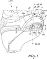
Figure 1 is a perspective view from below of the last; -
Figure 2 is a first exploded view of the last; -
Figure 3 is a second exploded view of the last; -
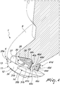
Figure 4 is a partially cross-sectional view of the main body and the insert in the condition before the extraction; -
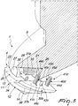
Figure 5 is a view similar to the previous figure of the main body and the insert in the initial condition of extraction; -
Figure 6 is a cross-sectional view of the last taken along the line VI-VI inFigure 1 ; -
Figure 7 is a cross-sectional view of the last inserted into the shell, taken along the line VII-VII inFigure 1 ; -
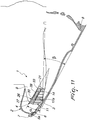
Figure 8 is a partially cross-sectional view taken along a longitudinal line of the last in a first step of unseating from the shell; -
Figure 9 is a view similar to the previous figure of the last in a second step of unseating from the shell; -
Figure 10 is a view similar toFigure 7 of the last in a third step of unseating from the shell; -
Figure 11 is a view similar to the previous figure of the last in the final step of unseating the last from the shell; -
Figure 12 is a cross-sectional view of the last, in a variation of embodiment thereof, inserted into the shell, taken along the line XII-XII inFigure 1 ; -
Figure 13 is a view similar to the previous figure of the last in a step of unseating from the shell. - In the embodiments illustrated below, individual characteristics shown in relation to specific examples may in reality be interchanged with other, different characteristics, existing in other embodiments.
- Moreover, it should be noted that anything found to be already known during the patenting process is understood not to be claimed and to be the subject of a disclaimer.
- With reference to the figures, the
reference numeral shell 2 of a boot provided with arigid sole 3 and, in thetoe region 4, at least onemetal plate - In the specific embodiment shown by way of non-limiting example, the
shell 2 is provided internally, proximate to thetoe region 4, with twometal plates first hole 6 accessible from inside theshell 2. - The last 1, 101 has a shape structure that substantially corresponds to that of the inside of the
shell 2 of a boot and therefore lacks thetoe unit 7 and theheel unit 8. - Such last 1, 101 is constituted by a
main body 9, which reproduces the internal shape structure of theshell 2 except for part of theregion 4, which corresponds to the toe of the foot, in which aflat recess 10 is obtained at which aninsert region 4, is slideably associated. - The
insert main body 9 of the last 1, 101 according to a plane that is inclined by a different angle α (alpha) to the normal angle β (beta) of extraction of theshell 2 from the last 1, 101, as shown inFigure 11 . - The
insert base 12 with a substantially rectangular shape structure from which afirst head insert - In the specific embodiment shown from
Figure 1 to Figure 10 by way of non-limiting example, theupper surface 20 of thefirst head 13 of theinsert 11 is flat. - In the specific embodiment shown in
Figures 10 and11 by way of non-limiting example, theupper surface 120 of thefirst head 113 of theinsert 111 is arc-shaped with the concavity facing away from the sole 3. - At the first
lower surface 14 of theinsert first seats diameter 16 of the semi-circumference of theinsert diameter 16. - The
first seats first pins first seats first pins first seats lower surface 14 of theinsert - The
first pins first holes 6 of themetal plates shell 2. - There are also two blind cylindrical
second seats lower surface 14 of theinsert first seats - The
second seats second pins second seat second pins second seats lower surface 14 of theinsert - The
second pins first pins first seats plates - The
first head insert upper surface diameter 16, with a tab orlug 21 that protrudes externally and at right angles to thefirst head - The
tab 21 has a preferably substantially curved shape structure in plan view. - Axially to the
main body 9, at the surface defined by therecess 10 and starting from the frontperimetric edge 22 of themain body 9, there is acentral cavity 23, which is semicircular and is as deep as theinsert perimetric edge 22, by thetab 21. - Once the
insert lower surface 24 of themain body 9, thecentral cavity 23 defines, together with the firstupper surface first head insert third seat 25 in which afirst pintle - The
first pintle second head front surface 34 of theinsert tab 21 and to be associated stably with themain body 9 of the last 1, 101, and afirst shank 28 which is adapted to extend in the direction of thetab 21. - The
second head first pintle lower surface upper surface insert - In the specific embodiment shown from
Figure 1 to Figure 10 by way of non-limiting example, the thirdlower surface 48 of thesecond head 27 of thefirst pintle 26 is therefore flat. - In the specific embodiment shown in
Figures 10 and11 by way of non-limiting example, the thirdlower surface 148 of thesecond head 127 of thefirst pintle 126 is therefore curved. - The
second head first pintle second hole 29 which is adapted to accommodate stably a cylindricalsecond pintle 30, theends fourth seats 32 that are arranged transversely to thethird seat 25 of themain body 9 at thetoe region 4. - The
first shank 28 has a length that is less than the distance between thesecond head tab 21 of theinsert - Coaxially to the
first shank 28 there is an elastically deformable means 33, such as a cylindrical spring, which has, when inactive, a length that is substantially equal to the distance between thesecond head tab 21 of theinsert first shank 28 of thefirst pintle - Thus, when inactive, the spring forces the
second head insert perimetric edge 22 of themain body 9 of the last 1, 101 is arranged flush with thefront surface 34 of theinsert toe region 4 of the last 1, 101. - A
plate first head insert - Each
plate perimetric edges 36 of thebase 12 of theinsert first head upper surface upper surface first head - Each
plate main body 9 of the last 1, 101 and is adapted to guide the movement of theinsert main body 9 of the last 1, 101. - Each
plate upper surface fifth seats third head second shank screw sixth seats third pin - The
second shanks screws third pins sixth seats - The threaded first upper ends 44a, 44b, 44c, 44d of the
second shanks third pins eighth seats lower surface 24 of themain body 9 of the last 1, 101. - Use of the solution is the following: once the process of thermoforming the plastic material in order to obtain the
shell 2 is finished, the step of unseating the last 1, 101 from theshell 2 begins, as shown inFigures 8 and 9 . - During the unseating, there is an initial locking in place of the
first pins first holes 6 of themetal plates shell 2; in this way, theinsert Figure 8 , themain body 9 of the last 1, 101 slides with respect to theinsert upper surface first head insert lower surface second head first pintle - The sliding of the
main body 9 of the last 1, 101 occurs in a stable and precise manner by virtue of the presence of theplates main body 9 of the last 1, 101 by virtue of thescrews third pins - Subsequently the sliding of the
main body 9 with respect to theinsert Figure 9 , makes it possible to obtain the necessary spaces for thefirst pins holes 6 of themetal plates Figure 10 and inFigure 13 , without creating effort or friction in themetal plates shell 2. - Furthermore, when the
first pins metal plates insert third seat 25 and adjacent to therecess 10 of themain body 9 of the last 1, 101, as shown inFigure 11 , thus allowing the extraction of the last 1, 101 from theshell 2 when the last 1, 101 reaches an inclination at an angle β (beta) that is adapted to allow its complete extraction from theshell 2. - Thus it has been found that the invention fully achieves the intended aim and objects, a last 1, 101 having been provided for obtaining a
shell 2 of a boot provided with a rigid sole 3 which can be unseated from thatshell 2 rapidly and simply, while at the same time keeping theshell 2 intact and free from deformations during the step of unseating, thus obtaining a high quality and safety of thatshell 2. - It has furthermore been found that the last 1, 101 reduces the times for producing and unseating the
shell 2. - It has furthermore been found that the last thus provided reduces the production costs of the
shell 2, by limiting the number of discards. - It has finally been found that the last 1, 101 makes it possible to obtain a
shell 2 that ensures an optimal and safe coupling with the bindings associated with skis. - Naturally the materials used as well as the dimensions of the individual components of the invention may be more relevant according to specific requirements.
- Where technical features mentioned in any claim are followed by reference signs, those reference signs have been included for the sole purpose of increasing the intelligibility of the claims and accordingly, such reference signs do not have any limiting effect on the interpretation of each element identified by way of example by such reference signs.
Claims (14)
- A last (1, 101) for obtaining a shell (2) of a boot provided with a rigid sole (3) and, in the toe region (4), at least one metal plate (5a, 5b), characterized in that it comprises a main body (9) with which an insert (11, 111) is slideably associated, at said toe region (4), and can slide with respect to said main body (9) along a plane that is inclined by a different angle to the normal angle of extraction of said last (1, 101) from said shell (2), at least two bevel-free first pins (17a, 17b) protruding downward from said insert (11, 111) and interacting selectively with said at least one metal plate (5a, 5b).
- The last (1, 101) according to claim 1, characterized in that it has a shape structure that substantially corresponds to the shape structure of the inside of said shell (2) of a boot and therefore lacks the toe unit (7) and the heel unit (8), said last (1, 101) being constituted by said main body (9), which reproduces the internal shape structure of said shell (2) except for part of said region (4), which corresponds to the toe of the foot, in which a flat recess (10) is obtained at which said insert (11, 111), which is shaped complementarily to said region (4), is slideably associated.
- The last (1, 101) according to claim 1, characterized in that said insert (11, 111), has, in a transverse cross-section, a base (12) with a substantially rectangular shape structure from which a first head (13, 113) protrudes axially with a shape structure, in a transverse cross-section, substantially like an upside-down isosceles trapezoid, whereas in plan view said insert (11, 111) has a substantially semicircular shape structure.
- The last (1, 101) according to one or more of the preceding claims, characterized in that at the first lower surface (14) of said insert (11, 111) at least two blind cylindrical first seats (15a, 15b), which have the same diameter and the same length, are arranged along a same chord that is parallel to the diameter (16) of the semi-circumference of said insert (11, 111), and are arranged proximate to the end that lies opposite said diameter (16), said first seats (15a, 15b) being adapted to accommodate said complementarily-shaped cylindrical bevel-free first pins (17a, 17b) which are slightly longer than the length of said first seats (15a, 15b) so that said first pins (17a, 17b), once accommodated in said first seats (15a, 15b), protrude externally and downward from said first lower surface (14) of said insert (11, 111), said first pins (17a, 17b) being adapted to be positioned and to interact selectively with first holes (6), which are provided in said metal plates (5a, 5b) of said shell (2) and are accessible from the inside of said shell (2).
- The last (1, 101) according to one or more of the preceding claims, characterized in that there are two blind cylindrical second seats (18a, 18b) at said first lower surface (14) of said insert (11, 111), which have different diameters and lengths and are arranged between said first seats (15a, 15b) and at a different chord, said second seats (18a, 18b) being adapted to accommodate two complementarily-shaped cylindrical second pins (19a, 19b), which have the same length as the corresponding said second seat (18a, 18b) so that said second pins (19a, 19b), once accommodated in said second seats (18a, 18b), are arranged substantially flush with said first lower surface (14) of said insert (11, 111), said second pins (19a, 19b) being adapted to contribute to the correct positioning of said first pins (17a, 17b) in said first seats (15a, 15b) since they constitute an element for abutment against said plates (5a, 5b).
- The last (1, 101) according to one or more of the preceding claims, characterized in that said first head (13, 113) of said insert (11, 111) is provided stably, at its first upper surface (20, 120) and in a region adjacent to said diameter (16), with a tab or lug (21) that protrudes externally and at right angles to said first head (13, 113), said tab (21) having a substantially curved shape structure in plan view.
- The last (1, 101) according to one or more of the preceding claims, characterized in that, axially to said main body (9), at the surface defined by said recess (10) and starting from the front perimetric edge (22) of said main body (9), there is a central cavity (23), which is semicircular and is as deep as said insert (11, 111) and is closed off, on the opposite side with respect to said front perimetric edge (22), by said tab (21), once said insert (11, 111) has been arranged adjacent to the second lower surface (24) of said main body (9) said central cavity (23) defining, together with said first upper surface (20, 120) of said first head (13, 113) of said insert (11, 111), a third seat (25) in which a first pintle (26, 126) is positioned.
- The last (1, 101) according to one or more of the preceding claims, characterized in that said first pintle (26, 126) is substantially T-shaped, a shape adapted to define a second head (27, 127), said second head being adapted to be positioned with one end flush with the front surface (34) of said insert (11, 111) on the opposite side from said tab (21) and to be associated stably with said main body (9) of said last (1, 101), and a first shank (28) which is adapted to extend in the direction of said tab (21), said second head (27, 127) of said first pintle (26, 126) having a third lower surface (48, 148) that is shaped substantially complementarily to said corresponding first upper surface (20, 120) of said insert (11, 111), said second head (27, 127) of said first pintle (26, 126) having a transverse second hole (29) which is adapted to accommodate stably a cylindrical second pintle (30), the ends (31a, 31b) of which are accommodated stably in transverse fourth seats (32) that are arranged transversely to said third seat (25) of said main body (9) at said toe region (4).
- The last (1, 101) according to one or more of the preceding claims, characterized in that said first shank (28) has a length that is less than the distance between said second head (27, 127) and said tab (21) of said insert (11, 111), coaxially to said first shank (28) there being an elastically deformable means (33) which has, when inactive, a length that is substantially equal to the distance between said second head (27, 127) and said tab (21) of said insert (11, 111) and therefore a length that is greater than the length of said first shank (28) of said first pintle (26, 126), said elastically deformable means (33), when inactive, forcing said second head (27, 127), and therefore all of said insert (11, 111), so that said front perimetric edge (22) of said main body (9) of said last (1, 101) is arranged flush with said front surface (34) of said insert (11, 111), thus creating a continuity of surfaces in said toe region (4) of said last (1, 101).
- The last (1, 101) according to one or more of the preceding claims, characterized in that a plate (35a, 35b) is associated slideably with each side of said first head (13, 113) of said insert (11, 111), each one of said plates (35a, 35b) having substantially the shape structure of a circular segment, so that its outer perimetric edges are arranged flush with the outer perimetric edges (36) of said base (12) of said insert (11, 111), and having a height that is equal to the height of said first head (13, 113) so that their second upper surface (37a, 37b) is arranged flush with said first upper surface (20, 120) of said first head (13, 113).
- The last (1, 101) according to one or more of the preceding claims, characterized in that each one of said plates (35a, 35b) is stably associated with said main body (9) of said last (1, 101) and is adapted to guide the movement of said insert (11, 111) with respect to said main body (9) of said last (1, 101), each plate (35a, 35b) having, at said second upper surface (37a, 37b), one or more blind fifth seats (38a, 38b, 38c, 38d), which are substantially T-shaped, each one adapted to stably accommodate a third head (39a, 39b, 39c, 39d) and a base of a second shank (40a, 40b, 40c, 40d) of a screw (41a, 41b, 41c, 41d) which is shaped complementarily thereto, and one or more cylindrical sixth seats (42a, 42b, 42c, 42d), each one adapted to accommodate a third pin (43a, 43b, 43c, 43d) which is shaped complementarily thereto.
- The last (1, 101) according to one or more of the preceding claims, characterized in that said second shanks (40a, 40b, 40c, 40d) of said screws (41a, 41b, 41c, 41d) and said third pins (43a, 43b, 43c, 43d) have a length that is greater than that of the corresponding said fifth and sixth seats (38a, 38b, 38c, 38d, 42a, 42b, 42c, 42d), the threaded first upper ends (44a, 44b, 44c, 44d) of said second shanks (40a, 40b, 40c, 40d) and the second upper ends (45a, 45b, 45c, 45d) of said third pins (43a, 43b, 43c, 43d) being accommodated stably in seventh and eighth seats (46a, 46b, 47a, 47b), which are provided at said second lower surface (24) of said main body (9) of said last.
- The last (1) according to one or more of the preceding claims, characterized in that said upper surface (20) of said first head (13) of said insert (11) and said third lower surface (48) of said second head (27) of said first pintle (26) are flat.
- The last (101) according to one or more of the preceding claims, characterized in that said upper surface (120) of said first head (113) of said insert (111) and said third lower surface (148) of said second head (127) of said first pintle (126) are arc-shaped with the concavity facing away from said sole (3).
Applications Claiming Priority (1)
| Application Number | Priority Date | Filing Date | Title |
|---|---|---|---|
| IT102016000118887A IT201600118887A1 (en) | 2016-11-24 | 2016-11-24 | SHAPE FOR OBTAINING A HULL OF A BOOT PRESENTING A RIGID SOLE. |
Publications (2)
| Publication Number | Publication Date |
|---|---|
| EP3326483A1 EP3326483A1 (en) | 2018-05-30 |
| EP3326483B1 true EP3326483B1 (en) | 2019-06-19 |
Family
ID=58266160
Family Applications (1)
| Application Number | Title | Priority Date | Filing Date |
|---|---|---|---|
| EP17202684.1A Active EP3326483B1 (en) | 2016-11-24 | 2017-11-21 | Last for obtaining a shell of a boot provided with a rigid sole |
Country Status (2)
| Country | Link |
|---|---|
| EP (1) | EP3326483B1 (en) |
| IT (1) | IT201600118887A1 (en) |
Cited By (1)
| Publication number | Priority date | Publication date | Assignee | Title |
|---|---|---|---|---|
| IT202300020028A1 (en) | 2023-09-28 | 2025-03-28 | Fmb S R L | MOLD FOR THE PRODUCTION, IN PARTICULAR BY INJECTION MOULDING OR VULCANIZATION, OF AN EXTERNAL SHELL OF A SKI BOOT AND RELATED METHOD. |
Family Cites Families (3)
| Publication number | Priority date | Publication date | Assignee | Title |
|---|---|---|---|---|
| DE860911C (en) * | 1950-04-20 | 1952-12-29 | Alfred De Craecker | Form and device for vulcanizing a sole on footwear and device for monitoring this device |
| AT293228B (en) * | 1965-03-08 | 1971-09-27 | Oskar Schmidt | Multi-part mold for the production of two-legged shoes |
| US3853446A (en) * | 1973-04-17 | 1974-12-10 | Inter Polymer Res Corp | Liquid injection molding apparatus |
-
2016
- 2016-11-24 IT IT102016000118887A patent/IT201600118887A1/en unknown
-
2017
- 2017-11-21 EP EP17202684.1A patent/EP3326483B1/en active Active
Non-Patent Citations (1)
| Title |
|---|
| None * |
Cited By (2)
| Publication number | Priority date | Publication date | Assignee | Title |
|---|---|---|---|---|
| IT202300020028A1 (en) | 2023-09-28 | 2025-03-28 | Fmb S R L | MOLD FOR THE PRODUCTION, IN PARTICULAR BY INJECTION MOULDING OR VULCANIZATION, OF AN EXTERNAL SHELL OF A SKI BOOT AND RELATED METHOD. |
| EP4530056A1 (en) | 2023-09-28 | 2025-04-02 | Fmb S.R.L. | Mold for the production, in particular for injection or vulcanization moulding, of an outer shell of a ski boot |
Also Published As
| Publication number | Publication date |
|---|---|
| EP3326483A1 (en) | 2018-05-30 |
| IT201600118887A1 (en) | 2018-05-24 |
Similar Documents
| Publication | Publication Date | Title |
|---|---|---|
| EP2946818B1 (en) | Front unit for a binding device and retractable pins device | |
| EP3326483B1 (en) | Last for obtaining a shell of a boot provided with a rigid sole | |
| EP3245891B1 (en) | Slide fastener | |
| US12539682B2 (en) | Moulding system for direct injection manufacturing of footwear | |
| US20110177186A1 (en) | Adjustable Shoe Mold Set | |
| CN102245405A (en) | System for changing sipe blades for molding or retreading tires | |
| US8752858B2 (en) | Ski, boot and binding between a ski and a boot | |
| US5056809A (en) | Safety ski binding | |
| US5871683A (en) | Method of molding skate components | |
| EP2591695A1 (en) | Element for fastening devices in particular for sport footwear and relative production process | |
| EP1473469A1 (en) | Rivet for the fastening of pieces to the bodywork of a vehicle | |
| US3350748A (en) | Quick change mold assemblies | |
| EP0441251A1 (en) | Ski fastening | |
| KR102394272B1 (en) | Clip bar support | |
| US20240293726A1 (en) | Toe-piece of a ski mountaineering binding | |
| EP2478788B1 (en) | Device for adjusting the position of the bootleg with respect to the shell, particularly for ski boots | |
| US7954841B2 (en) | Gliding board with rigidifying insert and method of manufacture | |
| JP2002225093A (en) | Injection mold | |
| US20070187926A1 (en) | Interface device for a gliding board, a gliding apparatus including such device, and a method of manufacture | |
| EP1602296B1 (en) | Ratchet device particularly for sports shoes | |
| KR100787192B1 (en) | Injection Mold Mold Assembly | |
| CN113519985B (en) | Detachable shoe last and preparation method thereof | |
| CN211363313U (en) | Demoulding structure for demoulding inner hole | |
| EP4046519B1 (en) | Footwear bottom with composite structure and process for the manufacturing of said bottom | |
| RU2362603C1 (en) | Automatic ski bindings |
Legal Events
| Date | Code | Title | Description |
|---|---|---|---|
| PUAI | Public reference made under article 153(3) epc to a published international application that has entered the european phase |
Free format text: ORIGINAL CODE: 0009012 |
|
| STAA | Information on the status of an ep patent application or granted ep patent |
Free format text: STATUS: THE APPLICATION HAS BEEN PUBLISHED |
|
| AK | Designated contracting states |
Kind code of ref document: A1 Designated state(s): AL AT BE BG CH CY CZ DE DK EE ES FI FR GB GR HR HU IE IS IT LI LT LU LV MC MK MT NL NO PL PT RO RS SE SI SK SM TR |
|
| AX | Request for extension of the european patent |
Extension state: BA ME |
|
| STAA | Information on the status of an ep patent application or granted ep patent |
Free format text: STATUS: REQUEST FOR EXAMINATION WAS MADE |
|
| 17P | Request for examination filed |
Effective date: 20181022 |
|
| RBV | Designated contracting states (corrected) |
Designated state(s): AL AT BE BG CH CY CZ DE DK EE ES FI FR GB GR HR HU IE IS IT LI LT LU LV MC MK MT NL NO PL PT RO RS SE SI SK SM TR |
|
| GRAP | Despatch of communication of intention to grant a patent |
Free format text: ORIGINAL CODE: EPIDOSNIGR1 |
|
| STAA | Information on the status of an ep patent application or granted ep patent |
Free format text: STATUS: GRANT OF PATENT IS INTENDED |
|
| INTG | Intention to grant announced |
Effective date: 20190110 |
|
| GRAS | Grant fee paid |
Free format text: ORIGINAL CODE: EPIDOSNIGR3 |
|
| GRAA | (expected) grant |
Free format text: ORIGINAL CODE: 0009210 |
|
| STAA | Information on the status of an ep patent application or granted ep patent |
Free format text: STATUS: THE PATENT HAS BEEN GRANTED |
|
| AK | Designated contracting states |
Kind code of ref document: B1 Designated state(s): AL AT BE BG CH CY CZ DE DK EE ES FI FR GB GR HR HU IE IS IT LI LT LU LV MC MK MT NL NO PL PT RO RS SE SI SK SM TR |
|
| REG | Reference to a national code |
Ref country code: GB Ref legal event code: FG4D |
|
| REG | Reference to a national code |
Ref country code: CH Ref legal event code: EP |
|
| REG | Reference to a national code |
Ref country code: IE Ref legal event code: FG4D |
|
| REG | Reference to a national code |
Ref country code: DE Ref legal event code: R096 Ref document number: 602017004666 Country of ref document: DE |
|
| REG | Reference to a national code |
Ref country code: AT Ref legal event code: REF Ref document number: 1144373 Country of ref document: AT Kind code of ref document: T Effective date: 20190715 |
|
| REG | Reference to a national code |
Ref country code: NL Ref legal event code: MP Effective date: 20190619 |
|
| PG25 | Lapsed in a contracting state [announced via postgrant information from national office to epo] |
Ref country code: NO Free format text: LAPSE BECAUSE OF FAILURE TO SUBMIT A TRANSLATION OF THE DESCRIPTION OR TO PAY THE FEE WITHIN THE PRESCRIBED TIME-LIMIT Effective date: 20190919 Ref country code: LT Free format text: LAPSE BECAUSE OF FAILURE TO SUBMIT A TRANSLATION OF THE DESCRIPTION OR TO PAY THE FEE WITHIN THE PRESCRIBED TIME-LIMIT Effective date: 20190619 Ref country code: FI Free format text: LAPSE BECAUSE OF FAILURE TO SUBMIT A TRANSLATION OF THE DESCRIPTION OR TO PAY THE FEE WITHIN THE PRESCRIBED TIME-LIMIT Effective date: 20190619 Ref country code: SE Free format text: LAPSE BECAUSE OF FAILURE TO SUBMIT A TRANSLATION OF THE DESCRIPTION OR TO PAY THE FEE WITHIN THE PRESCRIBED TIME-LIMIT Effective date: 20190619 Ref country code: HR Free format text: LAPSE BECAUSE OF FAILURE TO SUBMIT A TRANSLATION OF THE DESCRIPTION OR TO PAY THE FEE WITHIN THE PRESCRIBED TIME-LIMIT Effective date: 20190619 Ref country code: AL Free format text: LAPSE BECAUSE OF FAILURE TO SUBMIT A TRANSLATION OF THE DESCRIPTION OR TO PAY THE FEE WITHIN THE PRESCRIBED TIME-LIMIT Effective date: 20190619 |
|
| REG | Reference to a national code |
Ref country code: LT Ref legal event code: MG4D |
|
| PG25 | Lapsed in a contracting state [announced via postgrant information from national office to epo] |
Ref country code: GR Free format text: LAPSE BECAUSE OF FAILURE TO SUBMIT A TRANSLATION OF THE DESCRIPTION OR TO PAY THE FEE WITHIN THE PRESCRIBED TIME-LIMIT Effective date: 20190920 Ref country code: BG Free format text: LAPSE BECAUSE OF FAILURE TO SUBMIT A TRANSLATION OF THE DESCRIPTION OR TO PAY THE FEE WITHIN THE PRESCRIBED TIME-LIMIT Effective date: 20190919 Ref country code: RS Free format text: LAPSE BECAUSE OF FAILURE TO SUBMIT A TRANSLATION OF THE DESCRIPTION OR TO PAY THE FEE WITHIN THE PRESCRIBED TIME-LIMIT Effective date: 20190619 Ref country code: LV Free format text: LAPSE BECAUSE OF FAILURE TO SUBMIT A TRANSLATION OF THE DESCRIPTION OR TO PAY THE FEE WITHIN THE PRESCRIBED TIME-LIMIT Effective date: 20190619 |
|
| PG25 | Lapsed in a contracting state [announced via postgrant information from national office to epo] |
Ref country code: SK Free format text: LAPSE BECAUSE OF FAILURE TO SUBMIT A TRANSLATION OF THE DESCRIPTION OR TO PAY THE FEE WITHIN THE PRESCRIBED TIME-LIMIT Effective date: 20190619 Ref country code: PT Free format text: LAPSE BECAUSE OF FAILURE TO SUBMIT A TRANSLATION OF THE DESCRIPTION OR TO PAY THE FEE WITHIN THE PRESCRIBED TIME-LIMIT Effective date: 20191021 Ref country code: EE Free format text: LAPSE BECAUSE OF FAILURE TO SUBMIT A TRANSLATION OF THE DESCRIPTION OR TO PAY THE FEE WITHIN THE PRESCRIBED TIME-LIMIT Effective date: 20190619 Ref country code: RO Free format text: LAPSE BECAUSE OF FAILURE TO SUBMIT A TRANSLATION OF THE DESCRIPTION OR TO PAY THE FEE WITHIN THE PRESCRIBED TIME-LIMIT Effective date: 20190619 Ref country code: CZ Free format text: LAPSE BECAUSE OF FAILURE TO SUBMIT A TRANSLATION OF THE DESCRIPTION OR TO PAY THE FEE WITHIN THE PRESCRIBED TIME-LIMIT Effective date: 20190619 Ref country code: NL Free format text: LAPSE BECAUSE OF FAILURE TO SUBMIT A TRANSLATION OF THE DESCRIPTION OR TO PAY THE FEE WITHIN THE PRESCRIBED TIME-LIMIT Effective date: 20190619 |
|
| PG25 | Lapsed in a contracting state [announced via postgrant information from national office to epo] |
Ref country code: ES Free format text: LAPSE BECAUSE OF FAILURE TO SUBMIT A TRANSLATION OF THE DESCRIPTION OR TO PAY THE FEE WITHIN THE PRESCRIBED TIME-LIMIT Effective date: 20190619 Ref country code: IS Free format text: LAPSE BECAUSE OF FAILURE TO SUBMIT A TRANSLATION OF THE DESCRIPTION OR TO PAY THE FEE WITHIN THE PRESCRIBED TIME-LIMIT Effective date: 20191019 Ref country code: IT Free format text: LAPSE BECAUSE OF FAILURE TO SUBMIT A TRANSLATION OF THE DESCRIPTION OR TO PAY THE FEE WITHIN THE PRESCRIBED TIME-LIMIT Effective date: 20190619 Ref country code: SM Free format text: LAPSE BECAUSE OF FAILURE TO SUBMIT A TRANSLATION OF THE DESCRIPTION OR TO PAY THE FEE WITHIN THE PRESCRIBED TIME-LIMIT Effective date: 20190619 |
|
| PG25 | Lapsed in a contracting state [announced via postgrant information from national office to epo] |
Ref country code: TR Free format text: LAPSE BECAUSE OF FAILURE TO SUBMIT A TRANSLATION OF THE DESCRIPTION OR TO PAY THE FEE WITHIN THE PRESCRIBED TIME-LIMIT Effective date: 20190619 |
|
| PG25 | Lapsed in a contracting state [announced via postgrant information from national office to epo] |
Ref country code: PL Free format text: LAPSE BECAUSE OF FAILURE TO SUBMIT A TRANSLATION OF THE DESCRIPTION OR TO PAY THE FEE WITHIN THE PRESCRIBED TIME-LIMIT Effective date: 20190619 Ref country code: DK Free format text: LAPSE BECAUSE OF FAILURE TO SUBMIT A TRANSLATION OF THE DESCRIPTION OR TO PAY THE FEE WITHIN THE PRESCRIBED TIME-LIMIT Effective date: 20190619 |
|
| PG25 | Lapsed in a contracting state [announced via postgrant information from national office to epo] |
Ref country code: IS Free format text: LAPSE BECAUSE OF FAILURE TO SUBMIT A TRANSLATION OF THE DESCRIPTION OR TO PAY THE FEE WITHIN THE PRESCRIBED TIME-LIMIT Effective date: 20200224 |
|
| REG | Reference to a national code |
Ref country code: DE Ref legal event code: R097 Ref document number: 602017004666 Country of ref document: DE Ref country code: DE Ref legal event code: R119 Ref document number: 602017004666 Country of ref document: DE |
|
| PLBE | No opposition filed within time limit |
Free format text: ORIGINAL CODE: 0009261 |
|
| STAA | Information on the status of an ep patent application or granted ep patent |
Free format text: STATUS: NO OPPOSITION FILED WITHIN TIME LIMIT |
|
| REG | Reference to a national code |
Ref country code: AT Ref legal event code: UEP Ref document number: 1144373 Country of ref document: AT Kind code of ref document: T Effective date: 20190619 |
|
| PG2D | Information on lapse in contracting state deleted |
Ref country code: IS |
|
| PG25 | Lapsed in a contracting state [announced via postgrant information from national office to epo] |
Ref country code: MC Free format text: LAPSE BECAUSE OF FAILURE TO SUBMIT A TRANSLATION OF THE DESCRIPTION OR TO PAY THE FEE WITHIN THE PRESCRIBED TIME-LIMIT Effective date: 20190619 Ref country code: LU Free format text: LAPSE BECAUSE OF NON-PAYMENT OF DUE FEES Effective date: 20191121 |
|
| 26N | No opposition filed |
Effective date: 20200603 |
|
| REG | Reference to a national code |
Ref country code: BE Ref legal event code: MM Effective date: 20191130 |
|
| PG25 | Lapsed in a contracting state [announced via postgrant information from national office to epo] |
Ref country code: SI Free format text: LAPSE BECAUSE OF FAILURE TO SUBMIT A TRANSLATION OF THE DESCRIPTION OR TO PAY THE FEE WITHIN THE PRESCRIBED TIME-LIMIT Effective date: 20190619 |
|
| PG25 | Lapsed in a contracting state [announced via postgrant information from national office to epo] |
Ref country code: FR Free format text: LAPSE BECAUSE OF NON-PAYMENT OF DUE FEES Effective date: 20191130 Ref country code: DE Free format text: LAPSE BECAUSE OF NON-PAYMENT OF DUE FEES Effective date: 20200603 Ref country code: IE Free format text: LAPSE BECAUSE OF NON-PAYMENT OF DUE FEES Effective date: 20191121 |
|
| PG25 | Lapsed in a contracting state [announced via postgrant information from national office to epo] |
Ref country code: BE Free format text: LAPSE BECAUSE OF NON-PAYMENT OF DUE FEES Effective date: 20191130 |
|
| PG25 | Lapsed in a contracting state [announced via postgrant information from national office to epo] |
Ref country code: CY Free format text: LAPSE BECAUSE OF FAILURE TO SUBMIT A TRANSLATION OF THE DESCRIPTION OR TO PAY THE FEE WITHIN THE PRESCRIBED TIME-LIMIT Effective date: 20190619 |
|
| REG | Reference to a national code |
Ref country code: CH Ref legal event code: PL |
|
| PG25 | Lapsed in a contracting state [announced via postgrant information from national office to epo] |
Ref country code: MT Free format text: LAPSE BECAUSE OF FAILURE TO SUBMIT A TRANSLATION OF THE DESCRIPTION OR TO PAY THE FEE WITHIN THE PRESCRIBED TIME-LIMIT Effective date: 20190619 Ref country code: HU Free format text: LAPSE BECAUSE OF FAILURE TO SUBMIT A TRANSLATION OF THE DESCRIPTION OR TO PAY THE FEE WITHIN THE PRESCRIBED TIME-LIMIT; INVALID AB INITIO Effective date: 20171121 |
|
| PG25 | Lapsed in a contracting state [announced via postgrant information from national office to epo] |
Ref country code: CH Free format text: LAPSE BECAUSE OF NON-PAYMENT OF DUE FEES Effective date: 20201130 Ref country code: LI Free format text: LAPSE BECAUSE OF NON-PAYMENT OF DUE FEES Effective date: 20201130 |
|
| PG25 | Lapsed in a contracting state [announced via postgrant information from national office to epo] |
Ref country code: MK Free format text: LAPSE BECAUSE OF FAILURE TO SUBMIT A TRANSLATION OF THE DESCRIPTION OR TO PAY THE FEE WITHIN THE PRESCRIBED TIME-LIMIT Effective date: 20190619 |
|
| GBPC | Gb: european patent ceased through non-payment of renewal fee |
Effective date: 20211121 |
|
| PG25 | Lapsed in a contracting state [announced via postgrant information from national office to epo] |
Ref country code: GB Free format text: LAPSE BECAUSE OF NON-PAYMENT OF DUE FEES Effective date: 20211121 |
|
| PGFP | Annual fee paid to national office [announced via postgrant information from national office to epo] |
Ref country code: AT Payment date: 20251118 Year of fee payment: 9 |