EP4530047A1 - System and method for coupling a component to a gas turbine engine blade - Google Patents
System and method for coupling a component to a gas turbine engine blade Download PDFInfo
- Publication number
- EP4530047A1 EP4530047A1 EP24197141.5A EP24197141A EP4530047A1 EP 4530047 A1 EP4530047 A1 EP 4530047A1 EP 24197141 A EP24197141 A EP 24197141A EP 4530047 A1 EP4530047 A1 EP 4530047A1
- Authority
- EP
- European Patent Office
- Prior art keywords
- blade
- component
- plate
- pressure
- adhesive layer
- Prior art date
- Legal status (The legal status is an assumption and is not a legal conclusion. Google has not performed a legal analysis and makes no representation as to the accuracy of the status listed.)
- Granted
Links
Images





Classifications
-
- F—MECHANICAL ENGINEERING; LIGHTING; HEATING; WEAPONS; BLASTING
- F01—MACHINES OR ENGINES IN GENERAL; ENGINE PLANTS IN GENERAL; STEAM ENGINES
- F01D—NON-POSITIVE DISPLACEMENT MACHINES OR ENGINES, e.g. STEAM TURBINES
- F01D5/00—Blades; Blade-carrying members; Heating, heat-insulating, cooling or antivibration means on the blades or the members
- F01D5/12—Blades
- F01D5/28—Selecting particular materials; Particular measures relating thereto; Measures against erosion or corrosion
-
- B—PERFORMING OPERATIONS; TRANSPORTING
- B29—WORKING OF PLASTICS; WORKING OF SUBSTANCES IN A PLASTIC STATE IN GENERAL
- B29C—SHAPING OR JOINING OF PLASTICS; SHAPING OF MATERIAL IN A PLASTIC STATE, NOT OTHERWISE PROVIDED FOR; AFTER-TREATMENT OF THE SHAPED PRODUCTS, e.g. REPAIRING
- B29C65/00—Joining or sealing of preformed parts, e.g. welding of plastics materials; Apparatus therefor
- B29C65/02—Joining or sealing of preformed parts, e.g. welding of plastics materials; Apparatus therefor by heating, with or without pressure
- B29C65/18—Joining or sealing of preformed parts, e.g. welding of plastics materials; Apparatus therefor by heating, with or without pressure using heated tools
-
- B—PERFORMING OPERATIONS; TRANSPORTING
- B29—WORKING OF PLASTICS; WORKING OF SUBSTANCES IN A PLASTIC STATE IN GENERAL
- B29C—SHAPING OR JOINING OF PLASTICS; SHAPING OF MATERIAL IN A PLASTIC STATE, NOT OTHERWISE PROVIDED FOR; AFTER-TREATMENT OF THE SHAPED PRODUCTS, e.g. REPAIRING
- B29C65/00—Joining or sealing of preformed parts, e.g. welding of plastics materials; Apparatus therefor
- B29C65/02—Joining or sealing of preformed parts, e.g. welding of plastics materials; Apparatus therefor by heating, with or without pressure
- B29C65/18—Joining or sealing of preformed parts, e.g. welding of plastics materials; Apparatus therefor by heating, with or without pressure using heated tools
- B29C65/24—Joining or sealing of preformed parts, e.g. welding of plastics materials; Apparatus therefor by heating, with or without pressure using heated tools characterised by the means for heating the tool
- B29C65/30—Electrical means
- B29C65/305—Electrical means involving the use of cartridge heaters
-
- B—PERFORMING OPERATIONS; TRANSPORTING
- B29—WORKING OF PLASTICS; WORKING OF SUBSTANCES IN A PLASTIC STATE IN GENERAL
- B29C—SHAPING OR JOINING OF PLASTICS; SHAPING OF MATERIAL IN A PLASTIC STATE, NOT OTHERWISE PROVIDED FOR; AFTER-TREATMENT OF THE SHAPED PRODUCTS, e.g. REPAIRING
- B29C65/00—Joining or sealing of preformed parts, e.g. welding of plastics materials; Apparatus therefor
- B29C65/02—Joining or sealing of preformed parts, e.g. welding of plastics materials; Apparatus therefor by heating, with or without pressure
- B29C65/18—Joining or sealing of preformed parts, e.g. welding of plastics materials; Apparatus therefor by heating, with or without pressure using heated tools
- B29C65/24—Joining or sealing of preformed parts, e.g. welding of plastics materials; Apparatus therefor by heating, with or without pressure using heated tools characterised by the means for heating the tool
- B29C65/30—Electrical means
- B29C65/32—Induction
-
- B—PERFORMING OPERATIONS; TRANSPORTING
- B29—WORKING OF PLASTICS; WORKING OF SUBSTANCES IN A PLASTIC STATE IN GENERAL
- B29C—SHAPING OR JOINING OF PLASTICS; SHAPING OF MATERIAL IN A PLASTIC STATE, NOT OTHERWISE PROVIDED FOR; AFTER-TREATMENT OF THE SHAPED PRODUCTS, e.g. REPAIRING
- B29C65/00—Joining or sealing of preformed parts, e.g. welding of plastics materials; Apparatus therefor
- B29C65/48—Joining or sealing of preformed parts, e.g. welding of plastics materials; Apparatus therefor using adhesives, i.e. using supplementary joining material; solvent bonding
- B29C65/4805—Joining or sealing of preformed parts, e.g. welding of plastics materials; Apparatus therefor using adhesives, i.e. using supplementary joining material; solvent bonding characterised by the type of adhesives
- B29C65/483—Reactive adhesives, e.g. chemically curing adhesives
- B29C65/4835—Heat curing adhesives
-
- B—PERFORMING OPERATIONS; TRANSPORTING
- B29—WORKING OF PLASTICS; WORKING OF SUBSTANCES IN A PLASTIC STATE IN GENERAL
- B29C—SHAPING OR JOINING OF PLASTICS; SHAPING OF MATERIAL IN A PLASTIC STATE, NOT OTHERWISE PROVIDED FOR; AFTER-TREATMENT OF THE SHAPED PRODUCTS, e.g. REPAIRING
- B29C65/00—Joining or sealing of preformed parts, e.g. welding of plastics materials; Apparatus therefor
- B29C65/78—Means for handling the parts to be joined, e.g. for making containers or hollow articles, e.g. means for handling sheets, plates, web-like materials, tubular articles, hollow articles or elements to be joined therewith; Means for discharging the joined articles from the joining apparatus
- B29C65/7841—Holding or clamping means for handling purposes
-
- B—PERFORMING OPERATIONS; TRANSPORTING
- B29—WORKING OF PLASTICS; WORKING OF SUBSTANCES IN A PLASTIC STATE IN GENERAL
- B29C—SHAPING OR JOINING OF PLASTICS; SHAPING OF MATERIAL IN A PLASTIC STATE, NOT OTHERWISE PROVIDED FOR; AFTER-TREATMENT OF THE SHAPED PRODUCTS, e.g. REPAIRING
- B29C66/00—General aspects of processes or apparatus for joining preformed parts
- B29C66/40—General aspects of joining substantially flat articles, e.g. plates, sheets or web-like materials; Making flat seams in tubular or hollow articles; Joining single elements to substantially flat surfaces
- B29C66/47—Joining single elements to sheets, plates or other substantially flat surfaces
- B29C66/472—Joining single elements to sheets, plates or other substantially flat surfaces said single elements being substantially flat
- B29C66/4722—Fixing strips to surfaces other than edge faces
-
- B—PERFORMING OPERATIONS; TRANSPORTING
- B29—WORKING OF PLASTICS; WORKING OF SUBSTANCES IN A PLASTIC STATE IN GENERAL
- B29C—SHAPING OR JOINING OF PLASTICS; SHAPING OF MATERIAL IN A PLASTIC STATE, NOT OTHERWISE PROVIDED FOR; AFTER-TREATMENT OF THE SHAPED PRODUCTS, e.g. REPAIRING
- B29C66/00—General aspects of processes or apparatus for joining preformed parts
- B29C66/50—General aspects of joining tubular articles; General aspects of joining long products, i.e. bars or profiled elements; General aspects of joining single elements to tubular articles, hollow articles or bars; General aspects of joining several hollow-preforms to form hollow or tubular articles
- B29C66/51—Joining tubular articles, profiled elements or bars; Joining single elements to tubular articles, hollow articles or bars; Joining several hollow-preforms to form hollow or tubular articles
- B29C66/53—Joining single elements to tubular articles, hollow articles or bars
- B29C66/532—Joining single elements to the wall of tubular articles, hollow articles or bars
- B29C66/5326—Joining single elements to the wall of tubular articles, hollow articles or bars said single elements being substantially flat
-
- B—PERFORMING OPERATIONS; TRANSPORTING
- B29—WORKING OF PLASTICS; WORKING OF SUBSTANCES IN A PLASTIC STATE IN GENERAL
- B29C—SHAPING OR JOINING OF PLASTICS; SHAPING OF MATERIAL IN A PLASTIC STATE, NOT OTHERWISE PROVIDED FOR; AFTER-TREATMENT OF THE SHAPED PRODUCTS, e.g. REPAIRING
- B29C66/00—General aspects of processes or apparatus for joining preformed parts
- B29C66/70—General aspects of processes or apparatus for joining preformed parts characterised by the composition, physical properties or the structure of the material of the parts to be joined; Joining with non-plastics material
- B29C66/72—General aspects of processes or apparatus for joining preformed parts characterised by the composition, physical properties or the structure of the material of the parts to be joined; Joining with non-plastics material characterised by the structure of the material of the parts to be joined
- B29C66/721—Fibre-reinforced materials
-
- B—PERFORMING OPERATIONS; TRANSPORTING
- B29—WORKING OF PLASTICS; WORKING OF SUBSTANCES IN A PLASTIC STATE IN GENERAL
- B29C—SHAPING OR JOINING OF PLASTICS; SHAPING OF MATERIAL IN A PLASTIC STATE, NOT OTHERWISE PROVIDED FOR; AFTER-TREATMENT OF THE SHAPED PRODUCTS, e.g. REPAIRING
- B29C66/00—General aspects of processes or apparatus for joining preformed parts
- B29C66/70—General aspects of processes or apparatus for joining preformed parts characterised by the composition, physical properties or the structure of the material of the parts to be joined; Joining with non-plastics material
- B29C66/73—General aspects of processes or apparatus for joining preformed parts characterised by the composition, physical properties or the structure of the material of the parts to be joined; Joining with non-plastics material characterised by the intensive physical properties of the material of the parts to be joined, by the optical properties of the material of the parts to be joined, by the extensive physical properties of the parts to be joined, by the state of the material of the parts to be joined or by the material of the parts to be joined being a thermoplastic or a thermoset
- B29C66/731—General aspects of processes or apparatus for joining preformed parts characterised by the composition, physical properties or the structure of the material of the parts to be joined; Joining with non-plastics material characterised by the intensive physical properties of the material of the parts to be joined, by the optical properties of the material of the parts to be joined, by the extensive physical properties of the parts to be joined, by the state of the material of the parts to be joined or by the material of the parts to be joined being a thermoplastic or a thermoset characterised by the intensive physical properties of the material of the parts to be joined
- B29C66/7315—Mechanical properties
- B29C66/73151—Hardness
- B29C66/73152—Hardness of different hardness, i.e. the hardness of one of the parts to be joined being different from the hardness of the other part
-
- B—PERFORMING OPERATIONS; TRANSPORTING
- B29—WORKING OF PLASTICS; WORKING OF SUBSTANCES IN A PLASTIC STATE IN GENERAL
- B29C—SHAPING OR JOINING OF PLASTICS; SHAPING OF MATERIAL IN A PLASTIC STATE, NOT OTHERWISE PROVIDED FOR; AFTER-TREATMENT OF THE SHAPED PRODUCTS, e.g. REPAIRING
- B29C66/00—General aspects of processes or apparatus for joining preformed parts
- B29C66/80—General aspects of machine operations or constructions and parts thereof
- B29C66/81—General aspects of the pressing elements, i.e. the elements applying pressure on the parts to be joined in the area to be joined, e.g. the welding jaws or clamps
- B29C66/812—General aspects of the pressing elements, i.e. the elements applying pressure on the parts to be joined in the area to be joined, e.g. the welding jaws or clamps characterised by the composition, by the structure, by the intensive physical properties or by the optical properties of the material constituting the pressing elements, e.g. constituting the welding jaws or clamps
- B29C66/8122—General aspects of the pressing elements, i.e. the elements applying pressure on the parts to be joined in the area to be joined, e.g. the welding jaws or clamps characterised by the composition, by the structure, by the intensive physical properties or by the optical properties of the material constituting the pressing elements, e.g. constituting the welding jaws or clamps characterised by the composition of the material constituting the pressing elements, e.g. constituting the welding jaws or clamps
-
- B—PERFORMING OPERATIONS; TRANSPORTING
- B29—WORKING OF PLASTICS; WORKING OF SUBSTANCES IN A PLASTIC STATE IN GENERAL
- B29C—SHAPING OR JOINING OF PLASTICS; SHAPING OF MATERIAL IN A PLASTIC STATE, NOT OTHERWISE PROVIDED FOR; AFTER-TREATMENT OF THE SHAPED PRODUCTS, e.g. REPAIRING
- B29C66/00—General aspects of processes or apparatus for joining preformed parts
- B29C66/80—General aspects of machine operations or constructions and parts thereof
- B29C66/82—Pressure application arrangements, e.g. transmission or actuating mechanisms for joining tools or clamps
- B29C66/824—Actuating mechanisms
- B29C66/8242—Pneumatic or hydraulic drives
-
- B—PERFORMING OPERATIONS; TRANSPORTING
- B29—WORKING OF PLASTICS; WORKING OF SUBSTANCES IN A PLASTIC STATE IN GENERAL
- B29D—PRODUCING PARTICULAR ARTICLES FROM PLASTICS OR FROM SUBSTANCES IN A PLASTIC STATE
- B29D99/00—Subject matter not provided for in other groups of this subclass
- B29D99/0025—Producing blades or the like, e.g. blades for turbines, propellers, or wings
-
- F—MECHANICAL ENGINEERING; LIGHTING; HEATING; WEAPONS; BLASTING
- F01—MACHINES OR ENGINES IN GENERAL; ENGINE PLANTS IN GENERAL; STEAM ENGINES
- F01D—NON-POSITIVE DISPLACEMENT MACHINES OR ENGINES, e.g. STEAM TURBINES
- F01D25/00—Component parts, details, or accessories, not provided for in, or of interest apart from, other groups
- F01D25/28—Supporting or mounting arrangements, e.g. for turbine casing
- F01D25/285—Temporary support structures, e.g. for testing, assembling, installing, repairing; Assembly methods using such structures
-
- F—MECHANICAL ENGINEERING; LIGHTING; HEATING; WEAPONS; BLASTING
- F01—MACHINES OR ENGINES IN GENERAL; ENGINE PLANTS IN GENERAL; STEAM ENGINES
- F01D—NON-POSITIVE DISPLACEMENT MACHINES OR ENGINES, e.g. STEAM TURBINES
- F01D5/00—Blades; Blade-carrying members; Heating, heat-insulating, cooling or antivibration means on the blades or the members
- F01D5/30—Fixing blades to rotors; Blade roots ; Blade spacers
- F01D5/3092—Protective layers between blade root and rotor disc surfaces, e.g. anti-friction layers
-
- B—PERFORMING OPERATIONS; TRANSPORTING
- B29—WORKING OF PLASTICS; WORKING OF SUBSTANCES IN A PLASTIC STATE IN GENERAL
- B29C—SHAPING OR JOINING OF PLASTICS; SHAPING OF MATERIAL IN A PLASTIC STATE, NOT OTHERWISE PROVIDED FOR; AFTER-TREATMENT OF THE SHAPED PRODUCTS, e.g. REPAIRING
- B29C66/00—General aspects of processes or apparatus for joining preformed parts
- B29C66/70—General aspects of processes or apparatus for joining preformed parts characterised by the composition, physical properties or the structure of the material of the parts to be joined; Joining with non-plastics material
- B29C66/72—General aspects of processes or apparatus for joining preformed parts characterised by the composition, physical properties or the structure of the material of the parts to be joined; Joining with non-plastics material characterised by the structure of the material of the parts to be joined
- B29C66/721—Fibre-reinforced materials
- B29C66/7212—Fibre-reinforced materials characterised by the composition of the fibres
-
- B—PERFORMING OPERATIONS; TRANSPORTING
- B29—WORKING OF PLASTICS; WORKING OF SUBSTANCES IN A PLASTIC STATE IN GENERAL
- B29L—INDEXING SCHEME ASSOCIATED WITH SUBCLASS B29C, RELATING TO PARTICULAR ARTICLES
- B29L2031/00—Other particular articles
- B29L2031/08—Blades for rotors, stators, fans, turbines or the like, e.g. screw propellers
-
- F—MECHANICAL ENGINEERING; LIGHTING; HEATING; WEAPONS; BLASTING
- F05—INDEXING SCHEMES RELATING TO ENGINES OR PUMPS IN VARIOUS SUBCLASSES OF CLASSES F01-F04
- F05D—INDEXING SCHEME FOR ASPECTS RELATING TO NON-POSITIVE-DISPLACEMENT MACHINES OR ENGINES, GAS-TURBINES OR JET-PROPULSION PLANTS
- F05D2230/00—Manufacture
- F05D2230/60—Assembly methods
-
- F—MECHANICAL ENGINEERING; LIGHTING; HEATING; WEAPONS; BLASTING
- F05—INDEXING SCHEMES RELATING TO ENGINES OR PUMPS IN VARIOUS SUBCLASSES OF CLASSES F01-F04
- F05D—INDEXING SCHEME FOR ASPECTS RELATING TO NON-POSITIVE-DISPLACEMENT MACHINES OR ENGINES, GAS-TURBINES OR JET-PROPULSION PLANTS
- F05D2260/00—Function
- F05D2260/30—Retaining components in desired mutual position
-
- F—MECHANICAL ENGINEERING; LIGHTING; HEATING; WEAPONS; BLASTING
- F05—INDEXING SCHEMES RELATING TO ENGINES OR PUMPS IN VARIOUS SUBCLASSES OF CLASSES F01-F04
- F05D—INDEXING SCHEME FOR ASPECTS RELATING TO NON-POSITIVE-DISPLACEMENT MACHINES OR ENGINES, GAS-TURBINES OR JET-PROPULSION PLANTS
- F05D2300/00—Materials; Properties thereof
- F05D2300/40—Organic materials
- F05D2300/43—Synthetic polymers, e.g. plastics; Rubber
- F05D2300/431—Rubber
Definitions
- the present invention relates to a system and a method for coupling at least one component to a blade of the gas turbine engine.
- gas turbine engines include a fan that directs air towards a bypass duct and an engine core of the gas turbine engine.
- the fan includes a number of blades that are subjected to large amounts of centrifugal forces.
- a root area and an annulus area of each blade may be subjected to high amounts of wear.
- each blade typically includes wear resistant strips, such as a Vespel° strip manufactured by DuPont TM , attached proximal to the root area and the annulus area via a film adhesive so as to mitigate the wear of the blade, thereby protecting the blade.
- an outer surface of the wear resistant strips may be activated by means of a dry grit blast process to expose embedded polytetrafluoroethylene (PTFE) fibres in the wear resistant strip.
- the blade along with the wear resistant strips and the film adhesives are then cured under vacuum conditions, for example, in an autoclave. Further, curing of the film adhesive in the autoclave may incur high manufacturing costs, as high amounts of energy may be consumed during heating of the entire blade.
- Conventional methods of joining the wear resistant strip to the blade may cause the adhesive to have a non-uniform bond thickness between the wear resistant strip and the blade.
- oversized wear resistant strips are attached to the blade, and edges of the oversized wear resistant strips are later machined to meet tight tolerances. Such a machining operation may induce damage to the blade, which may in turn lead to delamination and in-service part repairs of the blade, thereby increasing manufacturing costs as well as maintenance costs associated with the blade.
- a system for coupling at least one component to a blade of a gas turbine engine includes a blade holder.
- the blade holder includes a plurality of side walls and a bottom wall connected to each of the plurality of side walls.
- the bottom wall and the plurality of side walls together define a receiving space to receive at least a portion of the blade and the at least one component therein.
- the system further includes an intensifier tool disposed on the at least one component.
- the intensifier tool includes a plate configured to contact the at least one component.
- the intensifier tool further includes a heating device coupled to the plate and configured to heat the at least one component.
- the system further includes an adhesive layer disposed between the at least one component and the blade.
- the system further includes a pressure strip coupled to the plate of the intensifier tool and the blade.
- the pressure strip fully encloses the plate.
- the system further includes a pressure applicator coupled to the pressure strip and configured to apply a pressure on the plate.
- the adhesive layer has a uniform bond thickness along a length of the at least one component due to the pressure applied by the pressure applicator. Upon being heated by the heating device, the adhesive layer is cured, thereby coupling the at least one component to the blade.
- the system of the present invention may provide a cost-effective approach to couple the at least one component to the blade.
- the system uses the heating device to cure the adhesive layer in order to couple the at least one component to the blade.
- the heating device may eliminate the requirement of heating the entire blade to cure the adhesive layer (for example, in an autoclave), which may save manufacturing costs.
- the system may provide faster curing cycles as only a portion of the blade is heated for curing the adhesive layer.
- the pressure strip may allow uniform distribution of the pressure (that is being applied by the pressure applicator) along a length of the plate.
- the pressure strip of the system may provide spew control, thereby providing the uniform bond thickness of the adhesive layer and minimal to no voids between the at least one component and the blade. As the voids are minimal, an adhesion between the at least one component and the blade may be improved, while also improving in-service life and functionality of the at least one component.
- the system may eliminate any additional steps of machining the at least one component, thereby maintaining the structural integrity of the at least one component as well as the blade.
- the at least one component may be of high quality and may be compliant with profile tolerances, surface tolerances, adhesive thickness, and porosity requirements.
- system described herein may be used as an on-site as well an off-site repair solution during servicing of the blades.
- the system may be portable and easy to use by operators for repair and maintenance of blades.
- the at least one component includes a Vespel° wear resistant strip, e.g. a Vespel ® wear resistant polyimide-based plastic strip manufactured by DuPont TM .
- a Vespel ® wear resistant polyimide-based plastic strip manufactured by DuPont TM .
- the Vespel ® strip may demonstrate properties, such as, heat resistance, lubricity, dimensional stability, chemical resistance, wear resistance, and creep resistance. Therefore, the Vespel ® strip may allow the blade to be used in hostile and extreme operating conditions, while preventing damage to the blade.
- the system described herein may be used to couple any other component to a portion of the gas turbine engine.
- the at least one component is made of a material that exhibits a coefficient of friction below 0.15, high load resistance, high temperature resistance, corrosion resistance, and/or wear resistance.
- the at least one component may allow the blade to be used in hostile and extreme operating conditions, while preventing damage to the blade.
- the pressure strip includes at least one of a butyl rubber, a platinum cured rubber, a silicone based rubber, and a peroxide cured rubber.
- the pressure strip made of one of the above listed rubbers may completely enclose the plate of the intensifier tool so as to prevent a flow-out of the adhesive layer. This may result in the uniform bond thickness and minimal to no voids in the adhesive layer, thereby improving adhesion between the at least one component and the blade, as well as improving in-service life and functionality of the at least one component.
- the system further includes an insulation layer disposed on the blade.
- the insulation layer is further at least partially disposed on the pressure strip.
- the insulation layer may cover the blade to minimize heat dissipation and may retain different curing temperatures localized at a root area and/or an annulus area of the blade.
- the insulation layer may prevent any damage to the blade due to overheating.
- the at least one component includes a plurality of first components configured to be coupled to the root area of the blade and a pair of second components configured to be coupled to the annulus area of the blade.
- the plurality of first components and the pair of second components may serve as sacrificial components to protect the blade from wear and damage.
- the system further includes at least one first temperature sensor configured to measure a first temperature proximal to the root area of the blade and at least one second temperature sensor configured to measure a second temperature proximal to the annulus area of the blade.
- the at least one first temperature sensor is disposed proximal to the root area and the at least one second temperature sensor is disposed proximal to the annulus area.
- the first temperature sensor and the second temperature sensor may measure the first and second temperatures proximal to the root area and the annulus area of the blade, respectively, so as to ensure that the first and second temperatures are sufficient to facilitate curing of the adhesive layer, without causing any damage to the at least one component, the blade, and/or the adhesive layer.
- the heating devices that is used to cure the adhesive layers associated with the first and second components, may be operated so as to maintain different first and second temperatures at the root area and the annulus area.
- the heating device together with the first and second temperature sensors may allow multi-zone temperature curing of the adhesive layer near the root area of the blade and the annulus area of the blade.
- the plate of the intensifier tool includes at least one of a carbon material and a metallic material.
- the plate of the intensifier tool may be cost-effective and portable and may also facilitate incorporation of the heating device.
- the heating device is at least partially embedded within the plate of the intensifier tool.
- the heating device may cure the adhesive layer to couple the at least one component to the blade.
- Such a heating device may provide a stand-alone curing solution, thereby eliminating use of the autoclave to cure the adhesive layer to couple the at least one component to the blade.
- the heating device may provide a portable solution for service and maintenance of the blade. The heating device may heat only the desired area of the blade instead of heating the entire blade, thereby preventing high energy consumption.
- the heating device includes at least one of an electric cartridge, a heated fabric, and a heated film.
- a heating device may provide a stand-alone curing solution, thereby eliminating use of the autoclave to cure the adhesive layer to couple the at least one component to the blade.
- the heating device may provide a portable solution for service and maintenance of the blade. The heating device may heat only the desired area of the blade instead of heating the entire blade, thereby preventing high energy consumption.
- the heating device includes at least one of a ceramic heater, an induction heater, and a heated fluid.
- a heating device may provide a stand-alone curing solution, thereby eliminating use of the autoclave to cure the adhesive layer to couple the at least one component to the blade.
- the heating device may provide a portable solution for service and maintenance of the blade. The heating device may heat only the desired area of the blade instead of heating the entire blade, thereby preventing high energy consumption.
- the pressure applicator includes one or more clamps configured to apply the pressure on the plate.
- the one or more clamps may ensure uniform application of pressure on the plate so that the at least one component may adhere to the blade in a desired manner, while maintaining the uniform bond thickness.
- a method of coupling at least one component to a blade of a gas turbine engine includes providing a blade holder including a plurality of side walls and a bottom wall connected to each of the plurality of side walls. The bottom wall and the plurality of side walls together define a receiving space. The method further includes disposing an adhesive layer between the at least one component and the blade. The method further includes placing the at least one component on the blade. The method further includes receiving at least a portion of the blade and the at least one component within the receiving space of the blade holder. The method further includes placing an intensifier tool on the at least one component.
- the intensifier tool includes a plate configured to contact the at least one component and a heating device coupled to the plate.
- the method further includes coupling a pressure strip to the plate of the intensifier tool and the blade.
- the pressure strip fully encloses the plate.
- the method further includes coupling a pressure applicator to the pressure strip.
- the method further includes applying, via the pressure applicator, a pressure on the plate of the intensifier tool.
- the method further includes providing a uniform bond thickness of the adhesive layer along a length of the at least one component based on the pressure applied by the pressure applicator.
- the method further includes heating, via the heating device of the intensifier tool, the at least one component to cure the adhesive layer, thereby coupling the at least one component to the blade.
- the method of the present invention may provide a cost saving approach to couple the at least one component to the blade.
- the method teaches use of the heating device to cure the adhesive layer in order to couple the at least one component to the blade.
- the method may eliminate the requirement of heating the entire blade to cure the adhesive layer (for example, in the autoclave), which may save manufacturing costs.
- the method may provide faster curing cycles as only some portion of the blade is heated for curing the adhesive layer.
- the method also teaches use of pressure strip that may provide spew control, thereby providing the uniform bond thickness of the adhesive layer and minimal to no voids between the at least one component and the blade. As the voids are minimal, an adhesion between the at least one component and the blade may be improved. Further, the method may eliminate any additional steps of machining the at least one component, thereby maintaining the structural integrity of the at least one component as well as the blade. Furthermore, the at least one component may be of high quality and may be compliant with profile tolerances, surface tolerances, adhesive thickness, and porosity requirements.
- the method described herein may be used as on-site as well an off-site repair solution during servicing of the blades. Furthermore, the method may provide operators a portable and easy-to-use solution for repair and maintenance of blades.
- the method further includes disposing an insulation layer on the blade after coupling the pressure strip to the plate of the intensifier tool and the blade.
- the insulation layer may cover the blade to minimize heat dissipation and may retain the different curing temperatures localized at a root area and/or an annulus area of the blade.
- the insulation layer may prevent damage to the blade due to overheating.
- the at least one component includes a plurality of first components configured to be coupled proximal to a root area of the blade and a pair of second components configured to be coupled proximal to an annulus area of the blade.
- the plurality of first components and the pair of second components may serve as sacrificial components to protect the blade from wear and damage.
- the method further includes measuring, via at least one first temperature sensor disposed proximal to the root area, a first temperature proximal to the root area of the blade.
- the method further includes controlling a first temperature proximal to the root area of the blade, such that the first temperature corresponds to a first predetermined temperature value.
- the first temperature sensor may measure the first temperature proximal to the root area so as to ensure that the first temperature proximal to the root area is sufficient to facilitate curing of the adhesive layer, without causing any damage to the plurality of first components, the root area, and/or the adhesive layer. Based on the value of the first temperature received from the first temperature sensor, the heating device, that is used to cure the adhesive layers associated with the plurality of first components, may be operated so as to maintain the first temperature at the root area.
- the method further includes measuring, via at least one second temperature sensor disposed proximal to the annulus area, a second temperature proximal to the annulus area of the blade.
- the method further incudes controlling the second temperature proximal to the annulus area of the blade, such that the second temperature corresponds to a second predetermined temperature value.
- the second temperature sensor may measure the second temperature proximal to the annulus area of the blade so as to ensure that the second temperature proximal to the annulus area is sufficient to facilitate curing of the adhesive layer, without causing any damage to the pair of second components, the annulus area, and/or the adhesive layer. Based on the value of the second temperature, the heating device, that is used to cure the adhesive layers associated with the pair of second components, may be operated so as to maintain the second temperature at the annulus area. Thus, the heating device together with the second temperature sensor may allow multi-zone temperature curing of the adhesive layer near the annulus area of the blade.
- the pressure applicator includes one or more clamps.
- the method further includes applying the pressure on the plate via the one or more clamps.
- the one or more clamps may ensure proper application of pressure on the plate such that the at least one component may properly adhere to the blade, while maintaining the uniform bond thickness.
- first”, “second”, and “third” are used as identifiers. Therefore, such terms should not be construed as limiting of this invention.
- the terms “first”, “second” and “third”, when used in conjunction with a feature or an element can be interchanged throughout the embodiments of this invention.
- the term “partially” refers to any percentage greater than 1%. In other words, the term “partially” refers to any amount of a whole. For example, “partially” may refer to a small portion, half, or a selected portion of a whole. In some cases, “partially” may refer to a whole amount. The term “partially” refers to any percentage less than 100%.
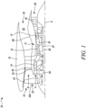
- FIG. 1 illustrates a schematic side view of a gas turbine engine 10 having a principal rotational axis 9.
- the gas turbine engine 10 comprises an air intake 12 and a propulsive fan 23 that generates two airflows: a core airflow A and a bypass airflow B.
- the gas turbine engine 10 comprises an engine core 11 that receives the core airflow A. In other words, the core airflow A enters the engine core 11.
- the fan 23 is located upstream of the engine core 11.
- the fan 23 includes a plurality of blades 100 (only one is shown herein for illustrative purposes) that upon rotating, generates the core airflow A and the bypass airflow B.
- the engine core 11 comprises, in axial flow series, a compressor, a combustor, and a turbine.
- the engine core 11 comprises, in axial flow series, a low pressure compressor 14, a high pressure compressor 15, a combustor 16, a high pressure turbine 17, a low pressure turbine 19, and a core exhaust nozzle 20.
- a nacelle 21 surrounds the gas turbine engine 10 and defines a bypass duct 22 and a bypass exhaust nozzle 18.
- the bypass airflow B flows through the bypass duct 22 surrounding the engine core 11.
- the bypass airflow B flows through the bypass duct 22 to provide propulsive thrust, where it is straightened by a row of outer guide vanes 40 before exiting the bypass exhaust nozzle 18.
- the outer guide vanes 40 extend radially outwardly from an inner ring 70 which defines a radially inner surface of the bypass duct 22.
- the engine core 11 is surrounded by an inner cowl 80 which provides an aerodynamic fairing defining an inner surface of the bypass duct 22.
- the inner cowl 80 is rearwards of and axially spaced from the inner ring 70.
- a fan case 42 defines an outer surface of the bypass duct 22.
- the inner ring 70 defines the inner surface of the bypass duct 22 towards the rear of the fan case 42.
- the fan 23 is attached to and driven by the low pressure turbine 19 via a shaft 26 and an epicyclic gearbox 30.
- the core airflow A is accelerated and compressed by the low pressure compressor 14 and directed into the high pressure compressor 15 where further compression takes place.
- the compressed air exhausted from the high pressure compressor 15 is directed into the combustor 16 where it is mixed with fuel and the mixture is combusted.
- the resultant hot combustion products then expand through, and thereby drive, the high pressure and low pressure turbines 17, 19 before being exhausted through the core exhaust nozzle 20 to provide some propulsive thrust.
- a core shaft 27 connects the turbine 17, 19 to the compressor 14, 15.
- the high pressure turbine 17 drives the high pressure compressor 15 by the suitable core shaft 27 or an interconnecting shaft.
- the fan 23 generally provides the majority of the propulsive thrust.
- the epicyclic gearbox 30 is a reduction gearbox.
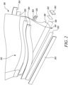
- FIG. 2 is a schematic perspective view of a portion of the blade 100 associated with the fan 23 shown in FIG. 1 , according to an embodiment of the present invention.
- the blade 100 includes an annulus area 102 and a root area 104.
- the annulus area 102 extends from the root area 104.
- the root area 104 of the blade 100 may include a dovetail root, a firtree root, or other type of root.
- the root area 104 of the blade 100 includes the dovetail root.
- the present invention is directed towards coupling of at least one component 202, 204 with the blade 100.
- the at least one component 202, 204 includes a plurality of first components 202 configured to be coupled to the root area 104 of the blade 100 and a pair of second components 204 configured to be coupled to the annulus area 102 of the blade 100.
- the plurality of first components 202 includes four first components 202 that are coupled to the root area 104 at each side of the blade 100.
- the plurality of first components 202 includes a first pair of the first components 202 coupled to the root area 104 of the blade 100 disposed opposite to each other and a second pair of the first components 202 configured to be coupled to corresponding flanks 106 (only one of which is shown herein) of the root area 104 of the blade 100.
- each of the first pair of the first components 202 is rectangular in shape and corresponds to a shape of the root area 104 at which the first component 202 is to be coupled.
- each of the second pair of first components 202 is rectangular in shape.
- each of the second pair of the first components 202 is rectangular in shape. In other examples, the second pair of first components 202 may have any other shape. Furthermore, the pair of second components 204 may have a curved shape similar to a shape of the annulus area 102 of the blade 100. Each of the first components 202 and the second components 204 are embodied as strips herein.
- the plurality of first components 202 and the pair of second components 204 may serve as sacrificial components to protect the blade 100 from wear and damage. Specifically, since the blade 100 may experience centrifugal forces during an operation of the gas turbine engine 10, the plurality of first components 202 and the pair of second components 204 may prevent the blade 100 from wear and damage.
- the at least one component 202, 204 includes a Vespel ® strip.
- the Vespel ® strip manufactured by DuPont TM is a polyamide-based plastic and may demonstrate properties, such as, heat resistance, lubricity, dimensional stability, chemical resistance, wear resistance, and creep resistance. Therefore, the Vespel ® strip may allow the blade 100 to be used in hostile and extreme operating conditions, while preventing damage to the blade 100.
- the at least one component 202, 204 may be made of any other material.
- the at least one component 202, 204 is made of a material that exhibits a coefficient of friction below 0.15, high load resistance, high temperature resistance, corrosion resistance, and/or wear resistance.
- the at least one component 202, 204 may allow the blade 100 to be used in hostile and extreme operating conditions, while preventing damage to the blade 100.
- the at least one component 202, 204 may be made of any fiber reinforced plastic.
- the material of the at least one component 202, 204 may have a lower hardness than the material of the blade 100 such that the at least one component 202, 204 acts as a sacrificial component and wears in use to protect the blade 100.
- FIG. 3 is a schematic perspective of a system 200 for coupling the at least one component 202, 204 to the blade 100 of the gas turbine engine 10 of FIG. 1 .
- the system 200 includes a blade holder 206.
- the blade holder 206 holds the blade 100 in a stationary condition during the coupling of the at least one component 202, 204 with the blade 100.
- the blade holder 206 includes a plurality of side walls 208. In the illustrated embodiment of FIG. 3 , the blade holder 206 includes four side walls 208.
- the blade holder 206 further includes a bottom wall 210 connected to each of the plurality of side walls 208.
- the bottom wall 210 and the plurality of side walls 208 together define a receiving space 212 to receive at least a portion 108 of the blade 100 and the at least one component 202 therein.
- the receiving space 212 receives the root area 104 of the blade 100 and the plurality of first component 202 therein.
- the blade holder 206 may be similar in shape to the root area 104 of the blade 100, so that the root area 104 of the blade 100 is receivable within the blade holder 206.
- the system 200 further includes an intensifier tool 214 disposed on the at least one component 202, 204.
- one intensifier tool 214 is disposed on each component 202, 204 to facilitate coupling of the corresponding component 202, 204 with the blade 100.
- the intensifier tool 214 coupled to the corresponding components 202, 204 are similar in terms of functionality and arrangement of devices, however, a shape and a size of the intensifier tool 214 may vary as per a shape and a size of the component 202, 204.
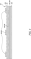
- FIG. 4 is a schematic cross-sectional view illustrating the intensifier tool 214.
- the intensifier tool 214 includes a plate 216 configured to contact the at least one component 202, 204.
- the plate 216 of the intensifier tool 214 includes at least one of a carbon material and a metallic material. It should be noted that a shape and a size of the plate 216 is similar to the shape and the size of the components 202, 204. Accordingly, the plate 216 may have a rectangular shape or a curved shape as per the shape of the components 202, 204, respectively.
- the intensifier tool 214 further includes a heating device 220 coupled to the plate 216 and configured to heat the at least one component 202, 204.
- the heating device 220 is at least partially embedded within the plate 216 of the intensifier tool 214.
- the heating device 220 includes at least one of an electric cartridge 232 (shown in FIG. 9 ), a heated fabric 230 (shown in FIG. 8 ), and a heated film 228.
- the heating device 220 includes the heated film 228 configured to heat the at least one component 202, 204.
- the heated film 228 may be embedded in the plate 216.
- the heated film 228 may heat the plate 216 and subsequently the component 202, 204 for curing an adhesive layer 222.
- the heated film 228 may be a metallic film .
- the heating device 220 includes at least one of a ceramic heater, an induction heater 234 (shown in FIG. 10 ), and a heated fluid 236 (shown in FIG. 11 ).
- the heating device 220 embodied as the ceramic heater (not shown) may be embedded in the plate 216.
- the ceramic heater may include a plurality of heating elements that may generate heat. Further, a temperature of the ceramic heater may be controlled by changing a voltage or an amperage applied to the heating elements of the ceramic heater.
- the plate 216 of the intensifier tool 214 described herein may be cost-effective and portable, and may also facilitate inclusion of the heating device 220.
- the system 200 further includes the adhesive layer 222 disposed between the at least one component 202, 204 and the blade 100.
- the adhesive layer 222 bonds the component 202, 204 to the blade 100 on heating.
- the adhesive layer 222 may include a high bonding adhesive.
- the adhesive layer 222 may include epoxy, without any limitations.
- the system 200 includes a pressure strip 224.
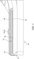
- FIG. 5 is a schematic cross-sectional view illustrating the pressure strip 224 coupled to the intensifier tool 214 and the blade 100.
- FIG. 6 is a schematic perspective view of the pressure strip 224 coupled to the plate 216 (see FIG. 5 ) and the blade 100.
- the pressure strip 224 fully encloses the plate 216.
- the pressure strip 224 is shown by a hatching in FIG. 6 to differentiate the pressure strip 224 from other parts of the blade 100.
- the pressure strip 224 includes at least one of a butyl rubber, a platinum cured rubber, a silicone based rubber, and a peroxide cured rubber.
- the pressure strip 224 made of one of the above listed rubbers may completely enclose the plate 216 of the intensifier tool 214 (see FIG. 5 ) so as to prevent a flow-out of the adhesive layer 222.
- the pressure strip 224 may result in the uniform bond thickness T1 (shown in FIG. 7 ), minimal or no voids in the adhesive layer 222, and improved adhesion between the at least one component 202, 204 (see FIG. 4 ) and the blade 100.
- the system 200 further includes a pressure applicator 218 coupled to the pressure strip 224 and configured to apply a pressure on the plate 216.
- the pressure strip 224 may allow uniform distribution of the pressure (that is being applied by the pressure applicator 218) along a length of the plate 216.
- the pressure applicator 218 includes one or more clamps 252 configured to apply the pressure on the plate 216.
- the pressure applicator 218 includes three clamps 252 that are equidistant from each other.
- the pressure applicator 218 may include any number of clamps 252 to apply uniform pressure on the plate 216.
- the clamps 252 are configured to hold the components 202, 204 received in the receiving space 212 of the blade holder 206 against the blade 100 during a clamping operation. Further, the clamps 252 may apply a controlled amount of the pressure on the plate 216. In some examples, the controlled amount of the pressure may be applied via pneumatics or hydraulics. Thus, the the pressure strip 224 and the pressure applicator 218 may together ensure uniform application of pressure on the plate 216 so that the at least one component 202, 204 may adhere to the blade 100 in a desired manner, while maintaining a uniform bond thickness T1 (shown in FIG. 7 ).
- the pressure applicator 218 may include any other component by which the pressure may be applied on the at least one component 202, 204, via the plate 216.
- the pressure applicator 218 may include a hydraulic or pneumatic device (such as, cylinder) to apply the pressure on the plate 216.
- the system 200 further includes an insulation layer 226 disposed on the blade 100.
- the insulation layer 226 is further at least partially disposed on the pressure strip 224.
- the insulation layer 226 may be disposed after the pressure strip 224 is coupled to the plate 216 and the blade 100. Further, the insulation layer 226 may be disposed after the pressure applicator 218 is coupled to the pressure strip 224.
- the insulation layer 226 may include a cut-out/opening to accommodate the pressure applicator 218.
- the insulation layer 226 encloses the blade 100 from the root area 104 up to the annulus area 102.
- the insulation layer 226 may cover the blade 100 to minimize heat dissipation and may retain different curing temperatures localized at the root area 104 and/or the annulus area 102 of the blade 100.
- the insulation layer 226 may prevent any damage to the blade 100 due to overheating.
- the system 200 further includes at least one first temperature sensor 238 configured to measure a first temperature S1 proximal to the root area 104 of the blade 100 and at least one second temperature sensor 240 configured to measure a second temperature S2 proximal to the annulus area 102 of the blade 100.
- the first temperature sensor 238 measures the first temperature S1 proximal to the root area 104 of the blade 100.
- the at least one first temperature sensor 238 may be disposed within the receiving space 212 of the blade holder 206.
- the first temperature S1 is measured so as to ensure that the first temperature S1 corresponds to a first predetermined temperature value V1 that is to be maintained in the root area 104.
- the first temperature S1 may lie in a range of 160 to 180 degrees.
- the second temperature sensor 240 measures the second temperature S2 proximal to the annulus area 102 of the blade 100.
- the at least one second temperature sensor 240 may be disposed proximal to the annulus area 102 and outside of the blade holder 206.
- the second temperature S2 is measured so as to ensure that the second temperature S2 corresponds to a second predetermined temperature value V2 that is to be maintained in the annulus area 102.
- the second temperature S2 may lie in a range of 110 to 130 degrees.
- the single first temperature sensor 238 and the single second temperature sensor 240 are shown, however, the system 200 may include multiple first and second temperature sensors 238, 240.
- the first temperature sensor 238 and the second temperature sensor 240 may measure the first and second temperatures S1, S2 proximal to the root area 104 and the annulus area 102 of the blade 100, respectively, so as to ensure that the first and second temperatures S1, S2 are sufficient to facilitate curing of the adhesive layer 222, without causing any damage to the at least one component 202, 204, the blade 100, and/or the adhesive layer 222.
- the heating devices 220 that is used to cure the adhesive layers 222, may be operated so as to maintain different first and second temperatures S1, S2 at the root area 104 and the annulus area 102.
- the heating device 220 together with the first and second temperature sensors 238, 240 may allow multi-zone temperature curing of the adhesive layer 222 near the root area 104 of the blade 100 and the annulus area 102 of the blade 100.
- the system 200 may include a controller (not shown) for controlling the heating device 220.
- the controller may receive values of the first and second temperatures S1, S2 from the first temperature sensor 238 and the second temperature sensor 240, respectively.
- the controller may further control the heating devices 220 to ensure that the first and second temperatures S1, S2 proximal to the root area 104 and the annulus area 102 correspond to the first and second predetermined temperature values V1, V2, respectively.
- the controller may be a control circuit, a computer, a microprocessor, a microcomputer, a central processing unit, or any suitable device or apparatus.
- FIG. 7 is a schematic cross-sectional view illustrating the at least one component 202 coupled to the root area 104 of the blade 100 via the adhesive layer 222.
- the adhesive layer 222 is cured, thereby coupling the at least one component 202 to the blade 100.
- the adhesive layer 222 has the uniform bond thickness T1 along a length L1 of the at least one component 202 due to the pressure applied by the pressure applicator 218.
- the adhesive layer 222 may have the uniform bond thickness T1 of greater than 0.075 millimetres (mm). Further, the system 200 may ensure substantially a smaller or no void formation between the at least one component 202, 204 and the blade 100. For example, the system 200 may ensure less than 2% of voids having a size of less than 6 mm between the at least one component 202, 204 and the blade 100, thereby improving adhesion between the at least one component 202, 204 and the blade 100, as well as improving in-service life and functionality of the component 202, 204.
- the system 200 of the present invention may provide a cost-effective approach to couple the at least one component 202, 204 to the blade 100.
- the system 200 uses the heating device 220 to cure the adhesive layer 222 in order to couple the at least one component 202, 204 to the blade 100.
- the heating device 220 may eliminate the requirement of heating the entire blade 100 to cure the adhesive layer 222 (for example, in an autoclave), which may save manufacturing costs.
- the system 200 may provide faster curing cycles as only some portion of the blade 100 is heated for curing the adhesive layer 222.
- the pressure strip 224 of the system 200 may provide spew control, thereby providing the uniform bond thickness T1 of the adhesive layer 222 and minimal to no voids between the at least one component 202, 204 and the blade 100. As the voids are minimal, an adhesion between the at least one component 202, 204 and the blade 100 may be improved, while also improving in-service life and functionality of the at least one component 202, 204. Further, the system 200 may eliminate any additional steps of machining the at least one component 202, 204, thereby maintaining the structural integrity of the at least one component 202, 204 as well as the blade 100. Furthermore, the at least one component 202, 204 may be of high quality and may be compliant with profile tolerances, surface tolerances, adhesive thickness, and porosity requirements.
- system 200 described herein may be used as an -site as well an off-site repair solution during servicing of the blades 100.
- the system 200 may be portable and easy-to-use by operators for repair and maintenance of blades 100. It should be noted that the system 200 may be used to couple any other component to the gas turbine engine 10.
- FIG. 8 is a schematic view of the heating device 220 of an intensifier tool of an embodiment of the system of the present disclosure.
- the heating device 220 includes the heated fabric 230 coupled to the plate 216 and configured to cure the adhesive layer 222 (see FIG. 4 ).
- the heated fabric 230 may be received within the plate 216.
- the heated fabric 230 may include non-metallic porous or perforated fabric heating elements. In some examples, the heating elements may be in the form of conductive yarns, filaments, fibres, wires, and the like.
- the heated fabric 230 may generate heat when a voltage is applied to the heating elements. The heat generated by the heated fabric 230 may cure the adhesive layer 222.
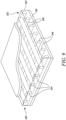
- FIG. 9 is a schematic view of the heating device 220 of an intensifier tool of another embodiment of the system of the present invention.
- the heating device 220 includes the electric cartridge 232 configured to cure the adhesive layer 222 (see FIG. 4 ).
- the electric cartridge 232 may be received within the plate 216.
- the electric cartridge 232 includes a casing 242.
- the electric cartridge 232 further includes one or more first heat pipes 244 and one or more second heat pipes 246 disposed orthogonal to the one or more first heat pipes 244.
- Each of the first and second heat pipes 244, 246 are disposed within the casing 242.
- the first and second heat pipes 244, 246 may generate heat when a voltage is applied to the first heat pipes 244 and/or the second heat pipes 246.
- the heat generated by the electric cartridge 232 may cure the adhesive layer 222.
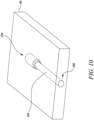
- FIG. 10 is a schematic view of the heating device 220 of an intensifier tool of yet another embodiment of the system of the present invention.
- the heating device 220 includes the induction heater 234 configured to cure the adhesive layer 222 (see FIG. 4 ).
- the induction heater 234 may be at least partially embedded within the plate 216.
- the induction heater 234 includes an inductor 248.
- the inductor 248 may be a copper inductor.
- the inductor 248 may be made of any other material configured to conduct heat and electricity.
- Induction heating may be achieved by applying a high-frequency current to the inductor 248, thereby generating a magnetic field around the inductor 248. The magnetic field induces eddy currents in a circular path in the plate 216, thereby generating heat.
- the heat generated by the induction heater 234 may cure the adhesive layer 222.
- FIG. 11 is a schematic view of the heating device 220 of an intensifier tool of a further embodiment of the system of the present invention.
- the heating device 220 includes the heated fluid 236 configured to cure the adhesive layer 222 (see FIG. 4 ).
- compressed air may be used as the heated fluid 236.
- the plate 216 may define at least one inlet flow channel 254 and at least one outlet flow channel 256 separated by the at least one inlet flow channel 254 via a divider 258.
- the heated fluid 236 may enter the plate 216 via the inlet flow channels 254 and exit the plate 216 via the outlet flow channels 256.
- the heated fluid 236 may generate heat to cure the adhesive layer 222 while flowing through the plate 216.
- flow conduits may be disposed within the plate 216 to define channels through which the heated fluid 236 may flow.
- FIG. 12 is a flowchart for a method 1200 of coupling the at least one component 202, 204 to the blade 100 of the gas turbine engine 10 of FIG. 1 , according to an embodiment of the present invention.
- the at least one component 202, 204 includes the plurality of first components 202 configured to be coupled proximal to the root area 104 of the blade 100 and the pair of second components 204 configured to be coupled proximal to the annulus area 102 of the blade 100.
- the blade holder 206 is provided.
- the blade holder 206 includes the plurality of side walls 208 and the bottom wall 210 connected to each of the plurality of side walls 208.
- the bottom wall 210 and the plurality of side walls 208 together define the receiving space 212.
- the adhesive layer 222 is disposed between the at least one component 202, 204 and the blade 100.
- the at least one component 202, 204 is placed on the blade 100.
- at least a portion 108 of the blade 100 and the at least one component 202, 204 is received within the receiving space 212 of the blade holder 206.
- the intensifier tool 214 is placed on the least one component 202, 204.
- the intensifier tool 214 includes the plate 216 configured to contact the at least one component 202, 204 and the heating device 220 coupled to the plate 216.
- the pressure strip 224 is coupled to the plate 216 of the intensifier tool 214 and the blade 100.
- the pressure strip 224 fully encloses the plate 216.
- the method 1200 further includes disposing the insulation layer 226 on the blade 100 after coupling the pressure strip 224 to the plate 216 of the intensifier tool 214 and the blade 100.
- the pressure applicator 218 is coupled to the pressure strip 224.
- the pressure applicator 218 applies the pressure on the plate 216 of the intensifier tool 214.
- the pressure applicator 218 includes the one or more clamps 252.
- the method 1200 further includes a step at which the one or more clamps 252 apply the pressure on the plate 216.
- the pressure applied by the pressure applicator 218 provides the uniform bond thickness T1 of the adhesive layer 222 along the length L1 of the at least one component 202, 204.
- the at least one component 202, 204 is heated via the heating device 220 to cure the adhesive layer 222, thereby coupling the at least one component 202, 204 to the blade 100.
- the method 1200 further includes a step of measuring, via the at least one first temperature sensor 238 disposed proximal to the root area 104, the first temperature S1 proximal to the root area 104 of the blade 100.
- the method 1200 further includes a step of controlling the first temperature S1 proximal to the root area 104 of the blade 100, such that the first temperature S1 corresponds to the first predetermined temperature value V1.
- the method 1200 further includes a step of measuring, via at least one second temperature sensor 240 disposed proximal to the annulus area 102, the second temperature S2 proximal to the annulus area 102 of the blade 100.
- the method 1200 further includes a step of controlling the second temperature S2 proximal to the annulus area 102 of the blade 100, such that the second temperature S2 corresponds to the second predetermined temperature value V2.
- the gas turbine engine 10 includes the at least one component 202, 204 manufactured by the method 1200 explained above.
Landscapes
- Engineering & Computer Science (AREA)
- Mechanical Engineering (AREA)
- General Engineering & Computer Science (AREA)
- Physics & Mathematics (AREA)
- Chemical & Material Sciences (AREA)
- Thermal Sciences (AREA)
- Materials Engineering (AREA)
- Fluid Mechanics (AREA)
- Chemical Kinetics & Catalysis (AREA)
- General Chemical & Material Sciences (AREA)
- Turbine Rotor Nozzle Sealing (AREA)
Abstract
Description
- The present invention relates to a system and a method for coupling at least one component to a blade of the gas turbine engine.
- Generally, gas turbine engines include a fan that directs air towards a bypass duct and an engine core of the gas turbine engine. The fan includes a number of blades that are subjected to large amounts of centrifugal forces. During an operation of the gas turbine engine, a root area and an annulus area of each blade may be subjected to high amounts of wear. Thus, each blade typically includes wear resistant strips, such as a Vespel° strip manufactured by DuPont™, attached proximal to the root area and the annulus area via a film adhesive so as to mitigate the wear of the blade, thereby protecting the blade.
- Conventionally, an outer surface of the wear resistant strips may be activated by means of a dry grit blast process to expose embedded polytetrafluoroethylene (PTFE) fibres in the wear resistant strip. The blade along with the wear resistant strips and the film adhesives are then cured under vacuum conditions, for example, in an autoclave. Further, curing of the film adhesive in the autoclave may incur high manufacturing costs, as high amounts of energy may be consumed during heating of the entire blade. Conventional methods of joining the wear resistant strip to the blade may cause the adhesive to have a non-uniform bond thickness between the wear resistant strip and the blade. In some conventional methods, oversized wear resistant strips are attached to the blade, and edges of the oversized wear resistant strips are later machined to meet tight tolerances. Such a machining operation may induce damage to the blade, which may in turn lead to delamination and in-service part repairs of the blade, thereby increasing manufacturing costs as well as maintenance costs associated with the blade.
- Thus, conventional techniques of coupling the wear resistant strip with the blade may be costly, may affect a quality of the blade, and may cause non-compliance with design requirements of the blade.
- In a first aspect, there is provided a system for coupling at least one component to a blade of a gas turbine engine. The system includes a blade holder. The blade holder includes a plurality of side walls and a bottom wall connected to each of the plurality of side walls. The bottom wall and the plurality of side walls together define a receiving space to receive at least a portion of the blade and the at least one component therein. The system further includes an intensifier tool disposed on the at least one component. The intensifier tool includes a plate configured to contact the at least one component. The intensifier tool further includes a heating device coupled to the plate and configured to heat the at least one component. The system further includes an adhesive layer disposed between the at least one component and the blade. The system further includes a pressure strip coupled to the plate of the intensifier tool and the blade. The pressure strip fully encloses the plate. The system further includes a pressure applicator coupled to the pressure strip and configured to apply a pressure on the plate. The adhesive layer has a uniform bond thickness along a length of the at least one component due to the pressure applied by the pressure applicator. Upon being heated by the heating device, the adhesive layer is cured, thereby coupling the at least one component to the blade.
- The system of the present invention may provide a cost-effective approach to couple the at least one component to the blade. Specifically, the system uses the heating device to cure the adhesive layer in order to couple the at least one component to the blade. Thus, the heating device may eliminate the requirement of heating the entire blade to cure the adhesive layer (for example, in an autoclave), which may save manufacturing costs. Further, the system may provide faster curing cycles as only a portion of the blade is heated for curing the adhesive layer.
- Further, as the pressure strip fully encloses the plate, the pressure strip may allow uniform distribution of the pressure (that is being applied by the pressure applicator) along a length of the plate. The pressure strip of the system may provide spew control, thereby providing the uniform bond thickness of the adhesive layer and minimal to no voids between the at least one component and the blade. As the voids are minimal, an adhesion between the at least one component and the blade may be improved, while also improving in-service life and functionality of the at least one component. Further, the system may eliminate any additional steps of machining the at least one component, thereby maintaining the structural integrity of the at least one component as well as the blade. Furthermore, the at least one component may be of high quality and may be compliant with profile tolerances, surface tolerances, adhesive thickness, and porosity requirements.
- Further, the system described herein may be used as an on-site as well an off-site repair solution during servicing of the blades. Furthermore, the system may be portable and easy to use by operators for repair and maintenance of blades.
- In some embodiments, the at least one component includes a Vespel° wear resistant strip, e.g. a Vespel® wear resistant polyimide-based plastic strip manufactured by DuPont™. It should be noted that the Vespel® strip may demonstrate properties, such as, heat resistance, lubricity, dimensional stability, chemical resistance, wear resistance, and creep resistance. Therefore, the Vespel® strip may allow the blade to be used in hostile and extreme operating conditions, while preventing damage to the blade. Alternatively, the system described herein may be used to couple any other component to a portion of the gas turbine engine.
- In some embodiments, the at least one component is made of a material that exhibits a coefficient of friction below 0.15, high load resistance, high temperature resistance, corrosion resistance, and/or wear resistance. Thus, the at least one component may allow the blade to be used in hostile and extreme operating conditions, while preventing damage to the blade.
- In some embodiments, the pressure strip includes at least one of a butyl rubber, a platinum cured rubber, a silicone based rubber, and a peroxide cured rubber. The pressure strip made of one of the above listed rubbers may completely enclose the plate of the intensifier tool so as to prevent a flow-out of the adhesive layer. This may result in the uniform bond thickness and minimal to no voids in the adhesive layer, thereby improving adhesion between the at least one component and the blade, as well as improving in-service life and functionality of the at least one component.
- In some embodiments, the system further includes an insulation layer disposed on the blade. The insulation layer is further at least partially disposed on the pressure strip. The insulation layer may cover the blade to minimize heat dissipation and may retain different curing temperatures localized at a root area and/or an annulus area of the blade. The insulation layer may prevent any damage to the blade due to overheating.
- In some embodiments, the at least one component includes a plurality of first components configured to be coupled to the root area of the blade and a pair of second components configured to be coupled to the annulus area of the blade. The plurality of first components and the pair of second components may serve as sacrificial components to protect the blade from wear and damage.
- In some embodiments, the system further includes at least one first temperature sensor configured to measure a first temperature proximal to the root area of the blade and at least one second temperature sensor configured to measure a second temperature proximal to the annulus area of the blade. The at least one first temperature sensor is disposed proximal to the root area and the at least one second temperature sensor is disposed proximal to the annulus area.
- The first temperature sensor and the second temperature sensor may measure the first and second temperatures proximal to the root area and the annulus area of the blade, respectively, so as to ensure that the first and second temperatures are sufficient to facilitate curing of the adhesive layer, without causing any damage to the at least one component, the blade, and/or the adhesive layer. Based on values of the first and second temperatures received from the first and second temperature sensors, the heating devices, that is used to cure the adhesive layers associated with the first and second components, may be operated so as to maintain different first and second temperatures at the root area and the annulus area. Thus, the heating device together with the first and second temperature sensors may allow multi-zone temperature curing of the adhesive layer near the root area of the blade and the annulus area of the blade.
- In some embodiments, the plate of the intensifier tool includes at least one of a carbon material and a metallic material. The plate of the intensifier tool may be cost-effective and portable and may also facilitate incorporation of the heating device.
- In some embodiments, the heating device is at least partially embedded within the plate of the intensifier tool. The heating device may cure the adhesive layer to couple the at least one component to the blade. Such a heating device may provide a stand-alone curing solution, thereby eliminating use of the autoclave to cure the adhesive layer to couple the at least one component to the blade. Further, the heating device may provide a portable solution for service and maintenance of the blade. The heating device may heat only the desired area of the blade instead of heating the entire blade, thereby preventing high energy consumption.
- In some embodiments, the heating device includes at least one of an electric cartridge, a heated fabric, and a heated film. Such a heating device may provide a stand-alone curing solution, thereby eliminating use of the autoclave to cure the adhesive layer to couple the at least one component to the blade. Further, the heating device may provide a portable solution for service and maintenance of the blade. The heating device may heat only the desired area of the blade instead of heating the entire blade, thereby preventing high energy consumption.
- In some embodiments, the heating device includes at least one of a ceramic heater, an induction heater, and a heated fluid. Such a heating device may provide a stand-alone curing solution, thereby eliminating use of the autoclave to cure the adhesive layer to couple the at least one component to the blade. Further, the heating device may provide a portable solution for service and maintenance of the blade. The heating device may heat only the desired area of the blade instead of heating the entire blade, thereby preventing high energy consumption.
- In some embodiments, the pressure applicator includes one or more clamps configured to apply the pressure on the plate. The one or more clamps may ensure uniform application of pressure on the plate so that the at least one component may adhere to the blade in a desired manner, while maintaining the uniform bond thickness.
- In a second aspect, there is provided a method of coupling at least one component to a blade of a gas turbine engine. The method includes providing a blade holder including a plurality of side walls and a bottom wall connected to each of the plurality of side walls. The bottom wall and the plurality of side walls together define a receiving space. The method further includes disposing an adhesive layer between the at least one component and the blade. The method further includes placing the at least one component on the blade. The method further includes receiving at least a portion of the blade and the at least one component within the receiving space of the blade holder. The method further includes placing an intensifier tool on the at least one component. The intensifier tool includes a plate configured to contact the at least one component and a heating device coupled to the plate. The method further includes coupling a pressure strip to the plate of the intensifier tool and the blade. The pressure strip fully encloses the plate. The method further includes coupling a pressure applicator to the pressure strip. The method further includes applying, via the pressure applicator, a pressure on the plate of the intensifier tool. The method further includes providing a uniform bond thickness of the adhesive layer along a length of the at least one component based on the pressure applied by the pressure applicator. The method further includes heating, via the heating device of the intensifier tool, the at least one component to cure the adhesive layer, thereby coupling the at least one component to the blade.
- The method of the present invention may provide a cost saving approach to couple the at least one component to the blade. The method teaches use of the heating device to cure the adhesive layer in order to couple the at least one component to the blade. Thus, the method may eliminate the requirement of heating the entire blade to cure the adhesive layer (for example, in the autoclave), which may save manufacturing costs. Further, the method may provide faster curing cycles as only some portion of the blade is heated for curing the adhesive layer.
- Further, the method also teaches use of pressure strip that may provide spew control, thereby providing the uniform bond thickness of the adhesive layer and minimal to no voids between the at least one component and the blade. As the voids are minimal, an adhesion between the at least one component and the blade may be improved. Further, the method may eliminate any additional steps of machining the at least one component, thereby maintaining the structural integrity of the at least one component as well as the blade. Furthermore, the at least one component may be of high quality and may be compliant with profile tolerances, surface tolerances, adhesive thickness, and porosity requirements.
- Further, the method described herein may be used as on-site as well an off-site repair solution during servicing of the blades. Furthermore, the method may provide operators a portable and easy-to-use solution for repair and maintenance of blades.
- In some embodiments, the method further includes disposing an insulation layer on the blade after coupling the pressure strip to the plate of the intensifier tool and the blade. The insulation layer may cover the blade to minimize heat dissipation and may retain the different curing temperatures localized at a root area and/or an annulus area of the blade. The insulation layer may prevent damage to the blade due to overheating.
- In some embodiments, the at least one component includes a plurality of first components configured to be coupled proximal to a root area of the blade and a pair of second components configured to be coupled proximal to an annulus area of the blade. The plurality of first components and the pair of second components may serve as sacrificial components to protect the blade from wear and damage.
- In some embodiments, the method further includes measuring, via at least one first temperature sensor disposed proximal to the root area, a first temperature proximal to the root area of the blade. The method further includes controlling a first temperature proximal to the root area of the blade, such that the first temperature corresponds to a first predetermined temperature value.
- The first temperature sensor may measure the first temperature proximal to the root area so as to ensure that the first temperature proximal to the root area is sufficient to facilitate curing of the adhesive layer, without causing any damage to the plurality of first components, the root area, and/or the adhesive layer. Based on the value of the first temperature received from the first temperature sensor, the heating device, that is used to cure the adhesive layers associated with the plurality of first components, may be operated so as to maintain the first temperature at the root area.
- In some embodiments, the method further includes measuring, via at least one second temperature sensor disposed proximal to the annulus area, a second temperature proximal to the annulus area of the blade. The method further incudes controlling the second temperature proximal to the annulus area of the blade, such that the second temperature corresponds to a second predetermined temperature value.
- The second temperature sensor may measure the second temperature proximal to the annulus area of the blade so as to ensure that the second temperature proximal to the annulus area is sufficient to facilitate curing of the adhesive layer, without causing any damage to the pair of second components, the annulus area, and/or the adhesive layer. Based on the value of the second temperature, the heating device, that is used to cure the adhesive layers associated with the pair of second components, may be operated so as to maintain the second temperature at the annulus area. Thus, the heating device together with the second temperature sensor may allow multi-zone temperature curing of the adhesive layer near the annulus area of the blade.
- In some embodiments, the pressure applicator includes one or more clamps. The method further includes applying the pressure on the plate via the one or more clamps. The one or more clamps may ensure proper application of pressure on the plate such that the at least one component may properly adhere to the blade, while maintaining the uniform bond thickness.
- Embodiments will now be described by way of example only, with reference to the Figures, in which:
-
FIG. 1 is a schematic side view of a gas turbine engine; -
FIG. 2 is a schematic perspective view illustrating first and second components to be coupled to a blade of the gas turbine engine ofFIG. 1 ; -
FIG. 3 is a schematic perspective view illustrating a portion of the blade and a system for coupling the components to the blade of the gas turbine engine ofFIG. 1 ; -
FIG. 4 is a schematic cross-sectional view of an intensifier tool associated with the system ofFIG. 3 ; -
FIG. 5 is a schematic cross-sectional view illustrating a pressure strip of the system coupled to the intensifier tool and the blade; -
FIG. 6 is a schematic perspective view of the pressure strip coupled to the intensifier tool and the blade; -
FIG. 7 is a schematic cross-sectional view illustrating the component coupled to the blade; -
FIG. 8 is a schematic view of a heating device of an intensifier tool of an embodiment of the system of the present invention; -
FIG. 9 is a schematic view of a heating device of an intensifier tool of another embodiment of the system of the present invention; -
FIG. 10 is a schematic view of a heating device of an intensifier tool of yet another embodiment of the system of the present invention; -
FIG. 11 is a schematic view of a heating device of an intensifier tool of a further embodiment of the system of the present invention; and -
FIG. 12 is a flowchart for a method of coupling the component to the blade of the gas turbine engine ofFIG. 1 , according to an embodiment of the present invention. - Aspects and embodiments of the present invention will now be discussed with reference to the accompanying figures. Further aspects and embodiments will be apparent to those skilled in the art.
- As used herein, the term "configured to" and like is at least as restrictive as the term "adapted to" and requires actual design intention to perform the specified function rather than mere physical capability of performing such a function.
- As used herein, the terms "first", "second", and "third" are used as identifiers. Therefore, such terms should not be construed as limiting of this invention. The terms "first", "second" and "third", when used in conjunction with a feature or an element can be interchanged throughout the embodiments of this invention.
- As used herein, "at least one of A and B" should be understood to mean "only A, only B, or both A and B".
- As used herein, the term "partially" refers to any percentage greater than 1%. In other words, the term "partially" refers to any amount of a whole. For example, "partially" may refer to a small portion, half, or a selected portion of a whole. In some cases, "partially" may refer to a whole amount. The term "partially" refers to any percentage less than 100%.
-
FIG. 1 illustrates a schematic side view of agas turbine engine 10 having a principalrotational axis 9. Thegas turbine engine 10 comprises anair intake 12 and apropulsive fan 23 that generates two airflows: a core airflow A and a bypass airflow B. Thegas turbine engine 10 comprises anengine core 11 that receives the core airflow A. In other words, the core airflow A enters theengine core 11. Thefan 23 is located upstream of theengine core 11. Thefan 23 includes a plurality of blades 100 (only one is shown herein for illustrative purposes) that upon rotating, generates the core airflow A and the bypass airflow B. Theengine core 11 comprises, in axial flow series, a compressor, a combustor, and a turbine. Specifically, theengine core 11 comprises, in axial flow series, alow pressure compressor 14, ahigh pressure compressor 15, acombustor 16, ahigh pressure turbine 17, alow pressure turbine 19, and acore exhaust nozzle 20. Anacelle 21 surrounds thegas turbine engine 10 and defines abypass duct 22 and abypass exhaust nozzle 18. The bypass airflow B flows through thebypass duct 22 surrounding theengine core 11. The bypass airflow B flows through thebypass duct 22 to provide propulsive thrust, where it is straightened by a row ofouter guide vanes 40 before exiting thebypass exhaust nozzle 18. Theouter guide vanes 40 extend radially outwardly from aninner ring 70 which defines a radially inner surface of thebypass duct 22. Rearward of theouter guide vanes 40, theengine core 11 is surrounded by aninner cowl 80 which provides an aerodynamic fairing defining an inner surface of thebypass duct 22. Theinner cowl 80 is rearwards of and axially spaced from theinner ring 70. Afan case 42 defines an outer surface of thebypass duct 22. Theinner ring 70 defines the inner surface of thebypass duct 22 towards the rear of thefan case 42. Thefan 23 is attached to and driven by thelow pressure turbine 19 via ashaft 26 and anepicyclic gearbox 30. - In use, the core airflow A is accelerated and compressed by the
low pressure compressor 14 and directed into thehigh pressure compressor 15 where further compression takes place. The compressed air exhausted from thehigh pressure compressor 15 is directed into thecombustor 16 where it is mixed with fuel and the mixture is combusted. The resultant hot combustion products then expand through, and thereby drive, the high pressure andlow pressure turbines core exhaust nozzle 20 to provide some propulsive thrust. Acore shaft 27 connects theturbine compressor high pressure turbine 17 drives thehigh pressure compressor 15 by thesuitable core shaft 27 or an interconnecting shaft. Thefan 23 generally provides the majority of the propulsive thrust. Theepicyclic gearbox 30 is a reduction gearbox. -
FIG. 2 is a schematic perspective view of a portion of theblade 100 associated with thefan 23 shown inFIG. 1 , according to an embodiment of the present invention. Although only thesingle blade 100 is being explained in detail, the details provided herein are equally applicable to allblades 100 of thefan 23, without any limitations. Theblade 100 includes anannulus area 102 and aroot area 104. Theannulus area 102 extends from theroot area 104. It should be noted that theroot area 104 of theblade 100 may include a dovetail root, a firtree root, or other type of root. In the illustrated embodiment ofFIG. 2 , theroot area 104 of theblade 100 includes the dovetail root. - The present invention is directed towards coupling of at least one
component blade 100. Specifically, the at least onecomponent first components 202 configured to be coupled to theroot area 104 of theblade 100 and a pair ofsecond components 204 configured to be coupled to theannulus area 102 of theblade 100. - The plurality of
first components 202 includes fourfirst components 202 that are coupled to theroot area 104 at each side of theblade 100. Particularly, the plurality offirst components 202 includes a first pair of thefirst components 202 coupled to theroot area 104 of theblade 100 disposed opposite to each other and a second pair of thefirst components 202 configured to be coupled to corresponding flanks 106 (only one of which is shown herein) of theroot area 104 of theblade 100. Further, each of the first pair of thefirst components 202 is rectangular in shape and corresponds to a shape of theroot area 104 at which thefirst component 202 is to be coupled. As shown inFIG. 2 , each of the second pair offirst components 202 is rectangular in shape. Further, each of the second pair of thefirst components 202 is rectangular in shape. In other examples, the second pair offirst components 202 may have any other shape. Furthermore, the pair ofsecond components 204 may have a curved shape similar to a shape of theannulus area 102 of theblade 100. Each of thefirst components 202 and thesecond components 204 are embodied as strips herein. - The plurality of
first components 202 and the pair ofsecond components 204 may serve as sacrificial components to protect theblade 100 from wear and damage. Specifically, since theblade 100 may experience centrifugal forces during an operation of thegas turbine engine 10, the plurality offirst components 202 and the pair ofsecond components 204 may prevent theblade 100 from wear and damage. In some embodiments, the at least onecomponent blade 100 to be used in hostile and extreme operating conditions, while preventing damage to theblade 100. - In other embodiments, the at least one
component component component blade 100 to be used in hostile and extreme operating conditions, while preventing damage to theblade 100. In some examples, the at least onecomponent component blade 100 such that the at least onecomponent blade 100. -
FIG. 3 is a schematic perspective of asystem 200 for coupling the at least onecomponent blade 100 of thegas turbine engine 10 ofFIG. 1 . Thesystem 200 includes ablade holder 206. Theblade holder 206 holds theblade 100 in a stationary condition during the coupling of the at least onecomponent blade 100. Theblade holder 206 includes a plurality ofside walls 208. In the illustrated embodiment ofFIG. 3 , theblade holder 206 includes fourside walls 208. - The
blade holder 206 further includes abottom wall 210 connected to each of the plurality ofside walls 208. Thebottom wall 210 and the plurality ofside walls 208 together define a receivingspace 212 to receive at least aportion 108 of theblade 100 and the at least onecomponent 202 therein. As is apparent fromFIG. 3 , the receivingspace 212 receives theroot area 104 of theblade 100 and the plurality offirst component 202 therein. Further, theblade holder 206 may be similar in shape to theroot area 104 of theblade 100, so that theroot area 104 of theblade 100 is receivable within theblade holder 206. - The
system 200 further includes anintensifier tool 214 disposed on the at least onecomponent intensifier tool 214 is disposed on eachcomponent corresponding component blade 100. Theintensifier tool 214 coupled to the correspondingcomponents intensifier tool 214 may vary as per a shape and a size of thecomponent -
FIG. 4 is a schematic cross-sectional view illustrating theintensifier tool 214. Theintensifier tool 214 includes aplate 216 configured to contact the at least onecomponent plate 216 of theintensifier tool 214 includes at least one of a carbon material and a metallic material. It should be noted that a shape and a size of theplate 216 is similar to the shape and the size of thecomponents plate 216 may have a rectangular shape or a curved shape as per the shape of thecomponents - The
intensifier tool 214 further includes aheating device 220 coupled to theplate 216 and configured to heat the at least onecomponent heating device 220 is at least partially embedded within theplate 216 of theintensifier tool 214. In some embodiments, theheating device 220 includes at least one of an electric cartridge 232 (shown inFIG. 9 ), a heated fabric 230 (shown inFIG. 8 ), and a heated film 228. In the illustrated embodiment ofFIG. 4 , theheating device 220 includes the heated film 228 configured to heat the at least onecomponent plate 216. The heated film 228 may heat theplate 216 and subsequently thecomponent adhesive layer 222. The heated film 228 may be a metallic film . - In some other embodiments, the
heating device 220 includes at least one of a ceramic heater, an induction heater 234 (shown inFIG. 10 ), and a heated fluid 236 (shown inFIG. 11 ). In some embodiments, theheating device 220 embodied as the ceramic heater (not shown) may be embedded in theplate 216. The ceramic heater may include a plurality of heating elements that may generate heat. Further, a temperature of the ceramic heater may be controlled by changing a voltage or an amperage applied to the heating elements of the ceramic heater. - It should be noted that the
plate 216 of theintensifier tool 214 described herein may be cost-effective and portable, and may also facilitate inclusion of theheating device 220. - Referring to
FIGS. 2 and4 , thesystem 200 further includes theadhesive layer 222 disposed between the at least onecomponent blade 100. Theadhesive layer 222 bonds thecomponent blade 100 on heating. In some examples, theadhesive layer 222 may include a high bonding adhesive. In an example, theadhesive layer 222 may include epoxy, without any limitations. - As shown in
FIG. 5 , thesystem 200 includes apressure strip 224.FIG. 5 is a schematic cross-sectional view illustrating thepressure strip 224 coupled to theintensifier tool 214 and theblade 100.FIG. 6 is a schematic perspective view of thepressure strip 224 coupled to the plate 216 (seeFIG. 5 ) and theblade 100. - Referring to
FIGS. 5 and6 , thepressure strip 224 fully encloses theplate 216. Thepressure strip 224 is shown by a hatching inFIG. 6 to differentiate thepressure strip 224 from other parts of theblade 100. In some embodiments, thepressure strip 224 includes at least one of a butyl rubber, a platinum cured rubber, a silicone based rubber, and a peroxide cured rubber. Thepressure strip 224 made of one of the above listed rubbers may completely enclose theplate 216 of the intensifier tool 214 (seeFIG. 5 ) so as to prevent a flow-out of theadhesive layer 222. Thepressure strip 224 may result in the uniform bond thickness T1 (shown inFIG. 7 ), minimal or no voids in theadhesive layer 222, and improved adhesion between the at least onecomponent 202, 204 (seeFIG. 4 ) and theblade 100. - As shown in
FIG. 4 , thesystem 200 further includes a pressure applicator 218 coupled to thepressure strip 224 and configured to apply a pressure on theplate 216. Further, as thepressure strip 224 fully encloses theplate 216, thepressure strip 224 may allow uniform distribution of the pressure (that is being applied by the pressure applicator 218) along a length of theplate 216. In some embodiments, the pressure applicator 218 includes one or more clamps 252 configured to apply the pressure on theplate 216. Specifically, the pressure applicator 218 includes three clamps 252 that are equidistant from each other. Alternatively, the pressure applicator 218 may include any number of clamps 252 to apply uniform pressure on theplate 216. The clamps 252 are configured to hold thecomponents space 212 of theblade holder 206 against theblade 100 during a clamping operation. Further, the clamps 252 may apply a controlled amount of the pressure on theplate 216. In some examples, the controlled amount of the pressure may be applied via pneumatics or hydraulics. Thus, the thepressure strip 224 and the pressure applicator 218 may together ensure uniform application of pressure on theplate 216 so that the at least onecomponent blade 100 in a desired manner, while maintaining a uniform bond thickness T1 (shown inFIG. 7 ). - It should be noted that the usage of clamps 252 for applying the pressure is exemplary in nature. Accordingly, the pressure applicator 218 may include any other component by which the pressure may be applied on the at least one
component plate 216. In some examples, the pressure applicator 218 may include a hydraulic or pneumatic device (such as, cylinder) to apply the pressure on theplate 216. - Referring now to
FIGS. 3 and5 , thesystem 200 further includes aninsulation layer 226 disposed on theblade 100. Theinsulation layer 226 is further at least partially disposed on thepressure strip 224. In other words, theinsulation layer 226 may be disposed after thepressure strip 224 is coupled to theplate 216 and theblade 100. Further, theinsulation layer 226 may be disposed after the pressure applicator 218 is coupled to thepressure strip 224. In some examples, theinsulation layer 226 may include a cut-out/opening to accommodate the pressure applicator 218. - Referring to
FIG. 3 , theinsulation layer 226 encloses theblade 100 from theroot area 104 up to theannulus area 102. Theinsulation layer 226 may cover theblade 100 to minimize heat dissipation and may retain different curing temperatures localized at theroot area 104 and/or theannulus area 102 of theblade 100. Theinsulation layer 226 may prevent any damage to theblade 100 due to overheating. - In some embodiments, the
system 200 further includes at least onefirst temperature sensor 238 configured to measure a first temperature S1 proximal to theroot area 104 of theblade 100 and at least onesecond temperature sensor 240 configured to measure a second temperature S2 proximal to theannulus area 102 of theblade 100. Specifically, thefirst temperature sensor 238 measures the first temperature S1 proximal to theroot area 104 of theblade 100. The at least onefirst temperature sensor 238 may be disposed within the receivingspace 212 of theblade holder 206. The first temperature S1 is measured so as to ensure that the first temperature S1 corresponds to a first predetermined temperature value V1 that is to be maintained in theroot area 104. In some examples, the first temperature S1 may lie in a range of 160 to 180 degrees. - Further, the
second temperature sensor 240 measures the second temperature S2 proximal to theannulus area 102 of theblade 100. The at least onesecond temperature sensor 240 may be disposed proximal to theannulus area 102 and outside of theblade holder 206. The second temperature S2 is measured so as to ensure that the second temperature S2 corresponds to a second predetermined temperature value V2 that is to be maintained in theannulus area 102. The second temperature S2 may lie in a range of 110 to 130 degrees. In the illustrated embodiment ofFIG. 3 , the singlefirst temperature sensor 238 and the singlesecond temperature sensor 240 are shown, however, thesystem 200 may include multiple first andsecond temperature sensors - The
first temperature sensor 238 and thesecond temperature sensor 240 may measure the first and second temperatures S1, S2 proximal to theroot area 104 and theannulus area 102 of theblade 100, respectively, so as to ensure that the first and second temperatures S1, S2 are sufficient to facilitate curing of theadhesive layer 222, without causing any damage to the at least onecomponent blade 100, and/or theadhesive layer 222. Based on the values of the first and second temperatures S1, S2 received from the first andsecond temperature sensors heating devices 220, that is used to cure theadhesive layers 222, may be operated so as to maintain different first and second temperatures S1, S2 at theroot area 104 and theannulus area 102. Thus, theheating device 220 together with the first andsecond temperature sensors adhesive layer 222 near theroot area 104 of theblade 100 and theannulus area 102 of theblade 100. - In some embodiments, the
system 200 may include a controller (not shown) for controlling theheating device 220. The controller may receive values of the first and second temperatures S1, S2 from thefirst temperature sensor 238 and thesecond temperature sensor 240, respectively. The controller may further control theheating devices 220 to ensure that the first and second temperatures S1, S2 proximal to theroot area 104 and theannulus area 102 correspond to the first and second predetermined temperature values V1, V2, respectively. In some examples, the controller may be a control circuit, a computer, a microprocessor, a microcomputer, a central processing unit, or any suitable device or apparatus. -
FIG. 7 is a schematic cross-sectional view illustrating the at least onecomponent 202 coupled to theroot area 104 of theblade 100 via theadhesive layer 222. Specifically, upon being heated by the heating device 220 (seeFIG. 4 ), theadhesive layer 222 is cured, thereby coupling the at least onecomponent 202 to theblade 100. As can be seen fromFIG. 7 , theadhesive layer 222 has the uniform bond thickness T1 along a length L1 of the at least onecomponent 202 due to the pressure applied by the pressure applicator 218. - In some examples, the
adhesive layer 222 may have the uniform bond thickness T1 of greater than 0.075 millimetres (mm). Further, thesystem 200 may ensure substantially a smaller or no void formation between the at least onecomponent blade 100. For example, thesystem 200 may ensure less than 2% of voids having a size of less than 6 mm between the at least onecomponent blade 100, thereby improving adhesion between the at least onecomponent blade 100, as well as improving in-service life and functionality of thecomponent - Referring to
FIGS. 1 to 7 , thesystem 200 of the present invention may provide a cost-effective approach to couple the at least onecomponent blade 100. Specifically, thesystem 200 uses theheating device 220 to cure theadhesive layer 222 in order to couple the at least onecomponent blade 100. Thus, theheating device 220 may eliminate the requirement of heating theentire blade 100 to cure the adhesive layer 222 (for example, in an autoclave), which may save manufacturing costs. Further, thesystem 200 may provide faster curing cycles as only some portion of theblade 100 is heated for curing theadhesive layer 222. - The
pressure strip 224 of thesystem 200 may provide spew control, thereby providing the uniform bond thickness T1 of theadhesive layer 222 and minimal to no voids between the at least onecomponent blade 100. As the voids are minimal, an adhesion between the at least onecomponent blade 100 may be improved, while also improving in-service life and functionality of the at least onecomponent system 200 may eliminate any additional steps of machining the at least onecomponent component blade 100. Furthermore, the at least onecomponent - Further, the
system 200 described herein may be used as an -site as well an off-site repair solution during servicing of theblades 100. Furthermore, thesystem 200 may be portable and easy-to-use by operators for repair and maintenance ofblades 100. It should be noted that thesystem 200 may be used to couple any other component to thegas turbine engine 10. -
FIG. 8 is a schematic view of theheating device 220 of an intensifier tool of an embodiment of the system of the present disclosure. Theheating device 220 includes theheated fabric 230 coupled to theplate 216 and configured to cure the adhesive layer 222 (seeFIG. 4 ). Theheated fabric 230 may be received within theplate 216. Theheated fabric 230 may include non-metallic porous or perforated fabric heating elements. In some examples, the heating elements may be in the form of conductive yarns, filaments, fibres, wires, and the like. Theheated fabric 230 may generate heat when a voltage is applied to the heating elements. The heat generated by theheated fabric 230 may cure theadhesive layer 222. -
FIG. 9 is a schematic view of theheating device 220 of an intensifier tool of another embodiment of the system of the present invention. Theheating device 220 includes theelectric cartridge 232 configured to cure the adhesive layer 222 (seeFIG. 4 ). Theelectric cartridge 232 may be received within theplate 216. Theelectric cartridge 232 includes acasing 242. Theelectric cartridge 232 further includes one or morefirst heat pipes 244 and one or moresecond heat pipes 246 disposed orthogonal to the one or morefirst heat pipes 244. Each of the first andsecond heat pipes casing 242. The first andsecond heat pipes first heat pipes 244 and/or thesecond heat pipes 246. The heat generated by theelectric cartridge 232 may cure theadhesive layer 222. -
FIG. 10 is a schematic view of theheating device 220 of an intensifier tool of yet another embodiment of the system of the present invention. Theheating device 220 includes theinduction heater 234 configured to cure the adhesive layer 222 (seeFIG. 4 ). Theinduction heater 234 may be at least partially embedded within theplate 216. Theinduction heater 234 includes aninductor 248. In some examples, theinductor 248 may be a copper inductor. In other examples, theinductor 248 may be made of any other material configured to conduct heat and electricity. Induction heating may be achieved by applying a high-frequency current to theinductor 248, thereby generating a magnetic field around theinductor 248. The magnetic field induces eddy currents in a circular path in theplate 216, thereby generating heat. The heat generated by theinduction heater 234 may cure theadhesive layer 222. -
FIG. 11 is a schematic view of theheating device 220 of an intensifier tool of a further embodiment of the system of the present invention. Theheating device 220 includes theheated fluid 236 configured to cure the adhesive layer 222 (seeFIG. 4 ). For example, compressed air may be used as theheated fluid 236. Theplate 216 may define at least oneinlet flow channel 254 and at least oneoutlet flow channel 256 separated by the at least oneinlet flow channel 254 via adivider 258. Theheated fluid 236 may enter theplate 216 via theinlet flow channels 254 and exit theplate 216 via theoutlet flow channels 256. Theheated fluid 236 may generate heat to cure theadhesive layer 222 while flowing through theplate 216. Alternatively, flow conduits may be disposed within theplate 216 to define channels through which theheated fluid 236 may flow. -
FIG. 12 is a flowchart for amethod 1200 of coupling the at least onecomponent blade 100 of thegas turbine engine 10 ofFIG. 1 , according to an embodiment of the present invention. The at least onecomponent first components 202 configured to be coupled proximal to theroot area 104 of theblade 100 and the pair ofsecond components 204 configured to be coupled proximal to theannulus area 102 of theblade 100. - With reference to
FIGS. 1 to 12 , atstep 1202, theblade holder 206 is provided. Theblade holder 206 includes the plurality ofside walls 208 and thebottom wall 210 connected to each of the plurality ofside walls 208. Thebottom wall 210 and the plurality ofside walls 208 together define the receivingspace 212. - At
step 1204 theadhesive layer 222 is disposed between the at least onecomponent blade 100. Atstep 1206, the at least onecomponent blade 100. Atstep 1208, at least aportion 108 of theblade 100 and the at least onecomponent space 212 of theblade holder 206. - At
step 1210, theintensifier tool 214 is placed on the least onecomponent intensifier tool 214 includes theplate 216 configured to contact the at least onecomponent heating device 220 coupled to theplate 216. - At
step 1212, thepressure strip 224 is coupled to theplate 216 of theintensifier tool 214 and theblade 100. Thepressure strip 224 fully encloses theplate 216. Themethod 1200 further includes disposing theinsulation layer 226 on theblade 100 after coupling thepressure strip 224 to theplate 216 of theintensifier tool 214 and theblade 100. - At
step 1214, the pressure applicator 218 is coupled to thepressure strip 224. - At
step 1216, the pressure applicator 218 applies the pressure on theplate 216 of theintensifier tool 214. In some embodiments, the pressure applicator 218 includes the one or more clamps 252. Themethod 1200 further includes a step at which the one or more clamps 252 apply the pressure on theplate 216. - At
step 1218, the pressure applied by the pressure applicator 218 provides the uniform bond thickness T1 of theadhesive layer 222 along the length L1 of the at least onecomponent - At
step 1220, the at least onecomponent heating device 220 to cure theadhesive layer 222, thereby coupling the at least onecomponent blade 100. - The
method 1200 further includes a step of measuring, via the at least onefirst temperature sensor 238 disposed proximal to theroot area 104, the first temperature S1 proximal to theroot area 104 of theblade 100. Themethod 1200 further includes a step of controlling the first temperature S1 proximal to theroot area 104 of theblade 100, such that the first temperature S1 corresponds to the first predetermined temperature value V1. - The
method 1200 further includes a step of measuring, via at least onesecond temperature sensor 240 disposed proximal to theannulus area 102, the second temperature S2 proximal to theannulus area 102 of theblade 100. Themethod 1200 further includes a step of controlling the second temperature S2 proximal to theannulus area 102 of theblade 100, such that the second temperature S2 corresponds to the second predetermined temperature value V2. - It should be noted that, during actual implementation, an order in which the steps of the
method 1200 are performed may vary from what is explained above and illustrated inFIG. 12 , as per requirements. - Further, the
gas turbine engine 10 includes the at least onecomponent method 1200 explained above.
Claims (15)
- A system (200) for coupling at least one component (202, 204) to a blade (100) of a gas turbine engine (10), the system (200) comprising:a blade holder (206) including:a plurality of side walls (208); anda bottom wall (210) connected to each of the plurality of side walls (208), wherein the bottom wall (210) and the plurality of side walls (208) together define a receiving space (212) to receive at least a portion (108) of the blade (100) and the at least one component (202, 204) therein;an intensifier tool (214) disposed on the at least one component (202, 204), wherein the intensifier tool (214) includes:a plate (216) configured to contact the at least one component (202, 204); anda heating device (220) coupled to the plate (216) and configured to heat the at least one component (202, 204);an adhesive layer (222) disposed between the at least one component (202, 204) and the blade (100);a pressure strip (224) coupled to the plate (216) of the intensifier tool (214) and the blade (100), wherein the pressure strip (224) fully encloses the plate (216); anda pressure applicator (218) coupled to the pressure strip (224) and configured to apply a pressure on the plate (216),wherein the adhesive layer (222) has a uniform bond thickness (T1) along a length (L1) of the at least one component (202, 204) due to the pressure applied by the pressure applicator (218), and wherein, upon being heated by the heating device (220), the adhesive layer (222) is cured, thereby coupling the at least one component (202, 204) to the blade (100).
- The system (200) of claim 1, wherein the at least one component (202, 204) includes a Vespel® wear resistant strip.
- The system (200) of claim 1 or 2, wherein the at least one component (202, 204) is made of a material that exhibits a coefficient of friction below 0.15, high load resistance, high temperature resistance, corrosion resistance, and/or wear resistance.
- The system (200) of any preceding claim, wherein the pressure strip (224) includes at least one of a butyl rubber, a platinum cured rubber, a silicone based rubber, and a peroxide cured rubber.
- The system (200) of any preceding claim, further comprising an insulation layer (226) disposed on the blade (100), wherein the insulation layer (226) is further at least partially disposed on the pressure strip (224).
- The system (200) of any preceding claim, wherein the at least one component (202, 204) includes a plurality of first components (202) configured to be coupled to a root area (104) of the blade (100) and a pair of second components (204) configured to be coupled to an annulus area (102) of the blade (100).
- The system (200) of claim 6, further comprising at least one first temperature sensor (238) configured to measure a first temperature (S1) proximal to the root area (104) of the blade (100) and at least one second temperature sensor (240) configured to measure a second temperature (S2) proximal to the annulus area (102) of the blade (100), wherein the at least one first temperature sensor (238) is disposed proximal to the root area (104) and the at least one second temperature sensor (240) is disposed proximal to the annulus area (102).
- The system (200) of any preceding claim, wherein the plate (216) of the intensifier tool (214) includes at least one of a carbon material and a metallic material.
- The system (200) of any preceding claim, wherein the heating device (220) is at least partially embedded within the plate (216) of the intensifier tool (214).
- The system (200) of claim 9, wherein the heating device (220) includes at least one of an electric cartridge (232), a heated fabric (230), and a heated film (228).
- The system (200) of any preceding claim, wherein the heating device (220) includes at least one of a ceramic heater, an induction heater (234), and a heated fluid (236).
- The system (200) of any preceding claim, wherein the pressure applicator (218) includes one or more clamps (252) configured to apply the pressure on the plate (216).
- A method (1200) of coupling at least one component (202, 204) to a blade (100) of a gas turbine engine (10), the method (1200) comprising:providing a blade holder (206) including a plurality of side walls (208) and a bottom wall (210) connected to each of the plurality of side walls (208), wherein the bottom wall (210) and the plurality of side walls (208) together define a receiving space (212);disposing an adhesive layer (222) between the at least one component (202, 204) and the blade (100);placing the at least one component (202, 204) on the blade (100);receiving at least a portion (108) of the blade (100) and the at least one component (202, 204) within the receiving space (212) of the blade holder (206);placing an intensifier tool (214) on the at least one component (202, 204), wherein the intensifier tool (214) includes a plate (216) configured to contact the at least one component (202, 204), a pressure applicator (218) coupled to the plate (216), and a heating device (220) coupled to the plate (216);coupling a pressure strip (224) to the plate (216) of the intensifier tool (214) and the blade (100), wherein the pressure strip (224) fully encloses the plate (216);coupling a pressure applicator (218) to the pressure strip (224);applying, via the pressure applicator (218), a pressure on the plate (216) of the intensifier tool (214);providing a uniform bond thickness (T1) of the adhesive layer (222) along a length (L1) of the at least one component (202, 204) based on the pressure applied by the pressure applicator (218); andheating, via the heating device (220) of the intensifier tool (214), the at least one component (202, 204) to cure the adhesive layer (222), thereby coupling the at least one component (202, 204) to the blade (100).
- The method (1200) of claim 13, further comprising disposing an insulation layer (226) on the blade (100) after coupling the pressure strip (224) to the plate (216) of the intensifier tool (214) and the blade (100).
- The method (1200) of claim 13 or 14, wherein the at least one component (202, 204) includes a plurality of first components (202) configured to be coupled proximal to a root area (104) of the blade (100) and a pair of second components (204) configured to be coupled proximal to an annulus area (102) of the blade (100).
Applications Claiming Priority (1)
| Application Number | Priority Date | Filing Date | Title |
|---|---|---|---|
| GBGB2314723.4A GB202314723D0 (en) | 2023-09-26 | 2023-09-26 | System and method for coupling component of gas turbine engine |
Publications (2)
| Publication Number | Publication Date |
|---|---|
| EP4530047A1 true EP4530047A1 (en) | 2025-04-02 |
| EP4530047B1 EP4530047B1 (en) | 2025-09-03 |
Family
ID=88599155
Family Applications (1)
| Application Number | Title | Priority Date | Filing Date |
|---|---|---|---|
| EP24197141.5A Active EP4530047B1 (en) | 2023-09-26 | 2024-08-29 | System and method for coupling a component to a gas turbine engine blade |
Country Status (3)
| Country | Link |
|---|---|
| US (1) | US20250101873A1 (en) |
| EP (1) | EP4530047B1 (en) |
| GB (1) | GB202314723D0 (en) |
Citations (3)
| Publication number | Priority date | Publication date | Assignee | Title |
|---|---|---|---|---|
| US20160076387A1 (en) * | 2013-05-06 | 2016-03-17 | Safran | Tooling for fastening metal reinforcement on the leading edge of a turbine engine blade, and a method using such tooling |
| FR3083568A1 (en) * | 2018-07-03 | 2020-01-10 | Safran | DEVICE FOR FIXING WEARBANDS WITH LOCALIZED HEATING |
| WO2021164958A1 (en) * | 2020-02-21 | 2021-08-26 | Rolls-Royce Plc | A fixing apparatus |
-
2023
- 2023-09-26 GB GBGB2314723.4A patent/GB202314723D0/en not_active Ceased
-
2024
- 2024-08-29 EP EP24197141.5A patent/EP4530047B1/en active Active
- 2024-09-05 US US18/825,368 patent/US20250101873A1/en active Pending
Patent Citations (3)
| Publication number | Priority date | Publication date | Assignee | Title |
|---|---|---|---|---|
| US20160076387A1 (en) * | 2013-05-06 | 2016-03-17 | Safran | Tooling for fastening metal reinforcement on the leading edge of a turbine engine blade, and a method using such tooling |
| FR3083568A1 (en) * | 2018-07-03 | 2020-01-10 | Safran | DEVICE FOR FIXING WEARBANDS WITH LOCALIZED HEATING |
| WO2021164958A1 (en) * | 2020-02-21 | 2021-08-26 | Rolls-Royce Plc | A fixing apparatus |
Also Published As
| Publication number | Publication date |
|---|---|
| US20250101873A1 (en) | 2025-03-27 |
| EP4530047B1 (en) | 2025-09-03 |
| GB202314723D0 (en) | 2023-11-08 |
Similar Documents
| Publication | Publication Date | Title |
|---|---|---|
| US5662757A (en) | Method of removing an abradable shroud assembly for turbomachinery | |
| EP2517865A1 (en) | Replacing an aperture in a laminated component | |
| CN107866685A (en) | For the tool holder component for the component for handling gas-turbine unit | |
| EP3569825A1 (en) | Electric heating for turbomachinery clearance control | |
| CN110886626B (en) | CMC component cooling cavity | |
| CA2809802A1 (en) | Gas turbine engine case with heating layer and method | |
| US20250101873A1 (en) | System and method for coupling a component to a gas turbine engine blade | |
| CN114851102A (en) | Compaction system and method for compacting composite material parts | |
| CN116078560B (en) | Temperature calibration device for in-situ heating of centrifuge under high speed and high temperature | |
| US11933195B2 (en) | Gas turbine engine with pre-conditioned ceramic matrix composite components | |
| US11105209B2 (en) | Turbine blade tip shroud | |
| CN110886625B (en) | Method of forming CMC component cooling cavity | |
| CA2945244C (en) | Fabrication of gas turbine engine components using multiple processing steps | |
| CN116637733B (en) | Temperature calibration test method for in-situ heating of centrifugal machine under high rotation speed and high temperature | |
| US12537421B2 (en) | Stator for electric machine | |
| US20250250913A1 (en) | System and method for assembling a fan case of a gas turbine engine | |
| EP3153673A1 (en) | Heating systems for rotor in-situ in turbomachines | |
| EP3153660A1 (en) | Heating systems for internally heating rotor in-situ in turbomachines, and related rotor | |
| CN114251127B (en) | Method for repairing composite parts and associated infiltration systems and methods | |
| US20230378827A1 (en) | Airgap cooling system for an electric machine | |
| EP4607006A1 (en) | System and method for assembling a fan case of a gas turbine engine | |
| US20180222172A1 (en) | Bonding of Turbomachinery Components | |
| EP4653325A1 (en) | Apparatus and method for measuring mechanical strain | |
| CN117231369A (en) | Insulating components for gas turbine engines | |
| CN121061790A (en) | Method for removing inserts from substrate |
Legal Events
| Date | Code | Title | Description |
|---|---|---|---|
| PUAI | Public reference made under article 153(3) epc to a published international application that has entered the european phase |
Free format text: ORIGINAL CODE: 0009012 |
|
| STAA | Information on the status of an ep patent application or granted ep patent |
Free format text: STATUS: REQUEST FOR EXAMINATION WAS MADE |
|
| 17P | Request for examination filed |
Effective date: 20250212 |
|
| AK | Designated contracting states |
Kind code of ref document: A1 Designated state(s): AL AT BE BG CH CY CZ DE DK EE ES FI FR GB GR HR HU IE IS IT LI LT LU LV MC ME MK MT NL NO PL PT RO RS SE SI SK SM TR |
|
| GRAP | Despatch of communication of intention to grant a patent |
Free format text: ORIGINAL CODE: EPIDOSNIGR1 |
|
| STAA | Information on the status of an ep patent application or granted ep patent |
Free format text: STATUS: GRANT OF PATENT IS INTENDED |
|
| GRAS | Grant fee paid |
Free format text: ORIGINAL CODE: EPIDOSNIGR3 |
|
| RIC1 | Information provided on ipc code assigned before grant |
Ipc: B29C 65/18 20060101AFI20250620BHEP Ipc: B29C 65/30 20060101ALI20250620BHEP Ipc: B29C 65/32 20060101ALI20250620BHEP Ipc: B29C 65/48 20060101ALI20250620BHEP Ipc: B29C 65/50 20060101ALI20250620BHEP Ipc: B29D 99/00 20100101ALI20250620BHEP Ipc: B29C 65/78 20060101ALI20250620BHEP Ipc: F01D 5/30 20060101ALI20250620BHEP Ipc: F01D 25/28 20060101ALI20250620BHEP Ipc: B29L 31/08 20060101ALN20250620BHEP |
|
| GRAA | (expected) grant |
Free format text: ORIGINAL CODE: 0009210 |
|
| STAA | Information on the status of an ep patent application or granted ep patent |
Free format text: STATUS: THE PATENT HAS BEEN GRANTED |
|
| INTG | Intention to grant announced |
Effective date: 20250707 |
|
| AK | Designated contracting states |
Kind code of ref document: B1 Designated state(s): AL AT BE BG CH CY CZ DE DK EE ES FI FR GB GR HR HU IE IS IT LI LT LU LV MC ME MK MT NL NO PL PT RO RS SE SI SK SM TR |
|
| P01 | Opt-out of the competence of the unified patent court (upc) registered |
Free format text: CASE NUMBER: UPC_APP_2370_4530047/2025 Effective date: 20250804 |
|
| REG | Reference to a national code |
Ref country code: CH Ref legal event code: EP |
|
| REG | Reference to a national code |
Ref country code: DE Ref legal event code: R096 Ref document number: 602024000589 Country of ref document: DE |
|
| REG | Reference to a national code |
Ref country code: IE Ref legal event code: FG4D |
|
| REG | Reference to a national code |
Ref country code: NL Ref legal event code: MP Effective date: 20250903 |
|
| PG25 | Lapsed in a contracting state [announced via postgrant information from national office to epo] |
Ref country code: NO Free format text: LAPSE BECAUSE OF FAILURE TO SUBMIT A TRANSLATION OF THE DESCRIPTION OR TO PAY THE FEE WITHIN THE PRESCRIBED TIME-LIMIT Effective date: 20251203 |
|
| REG | Reference to a national code |
Ref country code: LT Ref legal event code: MG9D |
|
| PG25 | Lapsed in a contracting state [announced via postgrant information from national office to epo] |
Ref country code: FI Free format text: LAPSE BECAUSE OF FAILURE TO SUBMIT A TRANSLATION OF THE DESCRIPTION OR TO PAY THE FEE WITHIN THE PRESCRIBED TIME-LIMIT Effective date: 20250903 |
|
| PG25 | Lapsed in a contracting state [announced via postgrant information from national office to epo] |
Ref country code: HR Free format text: LAPSE BECAUSE OF FAILURE TO SUBMIT A TRANSLATION OF THE DESCRIPTION OR TO PAY THE FEE WITHIN THE PRESCRIBED TIME-LIMIT Effective date: 20250903 |
|
| PG25 | Lapsed in a contracting state [announced via postgrant information from national office to epo] |
Ref country code: GR Free format text: LAPSE BECAUSE OF FAILURE TO SUBMIT A TRANSLATION OF THE DESCRIPTION OR TO PAY THE FEE WITHIN THE PRESCRIBED TIME-LIMIT Effective date: 20251204 |
|
| PG25 | Lapsed in a contracting state [announced via postgrant information from national office to epo] |
Ref country code: SE Free format text: LAPSE BECAUSE OF FAILURE TO SUBMIT A TRANSLATION OF THE DESCRIPTION OR TO PAY THE FEE WITHIN THE PRESCRIBED TIME-LIMIT Effective date: 20250903 |
|
| PG25 | Lapsed in a contracting state [announced via postgrant information from national office to epo] |
Ref country code: LV Free format text: LAPSE BECAUSE OF FAILURE TO SUBMIT A TRANSLATION OF THE DESCRIPTION OR TO PAY THE FEE WITHIN THE PRESCRIBED TIME-LIMIT Effective date: 20250903 |
|
| PG25 | Lapsed in a contracting state [announced via postgrant information from national office to epo] |
Ref country code: BG Free format text: LAPSE BECAUSE OF FAILURE TO SUBMIT A TRANSLATION OF THE DESCRIPTION OR TO PAY THE FEE WITHIN THE PRESCRIBED TIME-LIMIT Effective date: 20250903 Ref country code: PL Free format text: LAPSE BECAUSE OF FAILURE TO SUBMIT A TRANSLATION OF THE DESCRIPTION OR TO PAY THE FEE WITHIN THE PRESCRIBED TIME-LIMIT Effective date: 20250903 |
|
| PG25 | Lapsed in a contracting state [announced via postgrant information from national office to epo] |
Ref country code: RS Free format text: LAPSE BECAUSE OF FAILURE TO SUBMIT A TRANSLATION OF THE DESCRIPTION OR TO PAY THE FEE WITHIN THE PRESCRIBED TIME-LIMIT Effective date: 20251203 |
|
| PG25 | Lapsed in a contracting state [announced via postgrant information from national office to epo] |
Ref country code: ES Free format text: LAPSE BECAUSE OF FAILURE TO SUBMIT A TRANSLATION OF THE DESCRIPTION OR TO PAY THE FEE WITHIN THE PRESCRIBED TIME-LIMIT Effective date: 20250903 |
|
| REG | Reference to a national code |
Ref country code: AT Ref legal event code: MK05 Ref document number: 1832530 Country of ref document: AT Kind code of ref document: T Effective date: 20250903 |
|
| PG25 | Lapsed in a contracting state [announced via postgrant information from national office to epo] |
Ref country code: NL Free format text: LAPSE BECAUSE OF FAILURE TO SUBMIT A TRANSLATION OF THE DESCRIPTION OR TO PAY THE FEE WITHIN THE PRESCRIBED TIME-LIMIT Effective date: 20250903 |
|
| PG25 | Lapsed in a contracting state [announced via postgrant information from national office to epo] |
Ref country code: SM Free format text: LAPSE BECAUSE OF FAILURE TO SUBMIT A TRANSLATION OF THE DESCRIPTION OR TO PAY THE FEE WITHIN THE PRESCRIBED TIME-LIMIT Effective date: 20250903 |
|
| PG25 | Lapsed in a contracting state [announced via postgrant information from national office to epo] |
Ref country code: AT Free format text: LAPSE BECAUSE OF FAILURE TO SUBMIT A TRANSLATION OF THE DESCRIPTION OR TO PAY THE FEE WITHIN THE PRESCRIBED TIME-LIMIT Effective date: 20250903 |
|
| PG25 | Lapsed in a contracting state [announced via postgrant information from national office to epo] |
Ref country code: IT Free format text: LAPSE BECAUSE OF FAILURE TO SUBMIT A TRANSLATION OF THE DESCRIPTION OR TO PAY THE FEE WITHIN THE PRESCRIBED TIME-LIMIT Effective date: 20250903 |
|
| PG25 | Lapsed in a contracting state [announced via postgrant information from national office to epo] |
Ref country code: IS Free format text: LAPSE BECAUSE OF FAILURE TO SUBMIT A TRANSLATION OF THE DESCRIPTION OR TO PAY THE FEE WITHIN THE PRESCRIBED TIME-LIMIT Effective date: 20260103 |
|
| PG25 | Lapsed in a contracting state [announced via postgrant information from national office to epo] |
Ref country code: CZ Free format text: LAPSE BECAUSE OF FAILURE TO SUBMIT A TRANSLATION OF THE DESCRIPTION OR TO PAY THE FEE WITHIN THE PRESCRIBED TIME-LIMIT Effective date: 20250903 Ref country code: PT Free format text: LAPSE BECAUSE OF FAILURE TO SUBMIT A TRANSLATION OF THE DESCRIPTION OR TO PAY THE FEE WITHIN THE PRESCRIBED TIME-LIMIT Effective date: 20260105 |
|
| PG25 | Lapsed in a contracting state [announced via postgrant information from national office to epo] |
Ref country code: EE Free format text: LAPSE BECAUSE OF FAILURE TO SUBMIT A TRANSLATION OF THE DESCRIPTION OR TO PAY THE FEE WITHIN THE PRESCRIBED TIME-LIMIT Effective date: 20250903 Ref country code: SK Free format text: LAPSE BECAUSE OF FAILURE TO SUBMIT A TRANSLATION OF THE DESCRIPTION OR TO PAY THE FEE WITHIN THE PRESCRIBED TIME-LIMIT Effective date: 20250903 |