EP2354469A2 - Turbomachine Nacelle And Anti-Icing System And Method Therefor - Google Patents
Turbomachine Nacelle And Anti-Icing System And Method Therefor Download PDFInfo
- Publication number
- EP2354469A2 EP2354469A2 EP10195197A EP10195197A EP2354469A2 EP 2354469 A2 EP2354469 A2 EP 2354469A2 EP 10195197 A EP10195197 A EP 10195197A EP 10195197 A EP10195197 A EP 10195197A EP 2354469 A2 EP2354469 A2 EP 2354469A2
- Authority
- EP
- European Patent Office
- Prior art keywords
- nacelle
- heating element
- inlet lip
- heating
- cross
- Prior art date
- Legal status (The legal status is an assumption and is not a legal conclusion. Google has not performed a legal analysis and makes no representation as to the accuracy of the status listed.)
- Granted
Links
- 238000000034 method Methods 0.000 title claims abstract description 25
- 238000010438 heat treatment Methods 0.000 claims abstract description 105
- OKTJSMMVPCPJKN-UHFFFAOYSA-N Carbon Chemical compound [C] OKTJSMMVPCPJKN-UHFFFAOYSA-N 0.000 claims abstract description 27
- 239000002041 carbon nanotube Substances 0.000 claims abstract description 24
- 229910021393 carbon nanotube Inorganic materials 0.000 claims abstract description 23
- 239000002131 composite material Substances 0.000 claims description 21
- 238000010276 construction Methods 0.000 claims description 20
- 238000009413 insulation Methods 0.000 claims description 13
- 238000009434 installation Methods 0.000 claims description 2
- 239000000463 material Substances 0.000 description 22
- 239000011159 matrix material Substances 0.000 description 11
- 239000000835 fiber Substances 0.000 description 7
- 239000004753 textile Substances 0.000 description 7
- 239000004593 Epoxy Substances 0.000 description 6
- 230000002787 reinforcement Effects 0.000 description 6
- 229920005989 resin Polymers 0.000 description 5
- 239000011347 resin Substances 0.000 description 5
- 230000008901 benefit Effects 0.000 description 4
- 239000011162 core material Substances 0.000 description 4
- 239000004744 fabric Substances 0.000 description 4
- 239000002071 nanotube Substances 0.000 description 4
- 229910000838 Al alloy Inorganic materials 0.000 description 3
- RYGMFSIKBFXOCR-UHFFFAOYSA-N Copper Chemical compound [Cu] RYGMFSIKBFXOCR-UHFFFAOYSA-N 0.000 description 3
- 239000003795 chemical substances by application Substances 0.000 description 3
- 229910052802 copper Inorganic materials 0.000 description 3
- 239000010949 copper Substances 0.000 description 3
- 238000010292 electrical insulation Methods 0.000 description 3
- 239000000446 fuel Substances 0.000 description 3
- XPFVYQJUAUNWIW-UHFFFAOYSA-N furfuryl alcohol Chemical compound OCC1=CC=CO1 XPFVYQJUAUNWIW-UHFFFAOYSA-N 0.000 description 3
- 239000007770 graphite material Substances 0.000 description 3
- 229910001092 metal group alloy Inorganic materials 0.000 description 3
- 239000000126 substance Substances 0.000 description 3
- 238000012546 transfer Methods 0.000 description 3
- 239000004952 Polyamide Substances 0.000 description 2
- 239000004734 Polyphenylene sulfide Substances 0.000 description 2
- 239000000853 adhesive Substances 0.000 description 2
- 230000001070 adhesive effect Effects 0.000 description 2
- 238000009954 braiding Methods 0.000 description 2
- 239000000567 combustion gas Substances 0.000 description 2
- 238000002485 combustion reaction Methods 0.000 description 2
- 238000005516 engineering process Methods 0.000 description 2
- 239000000284 extract Substances 0.000 description 2
- 239000002657 fibrous material Substances 0.000 description 2
- 239000006260 foam Substances 0.000 description 2
- 239000007789 gas Substances 0.000 description 2
- 238000004519 manufacturing process Methods 0.000 description 2
- 239000000203 mixture Substances 0.000 description 2
- -1 poly(aryl) Polymers 0.000 description 2
- 229920002647 polyamide Polymers 0.000 description 2
- 229920000647 polyepoxide Polymers 0.000 description 2
- 229920000069 polyphenylene sulfide Polymers 0.000 description 2
- 230000001737 promoting effect Effects 0.000 description 2
- 238000001721 transfer moulding Methods 0.000 description 2
- 238000009941 weaving Methods 0.000 description 2
- 229920000049 Carbon (fiber) Polymers 0.000 description 1
- 230000002411 adverse Effects 0.000 description 1
- 229910052782 aluminium Inorganic materials 0.000 description 1
- XAGFODPZIPBFFR-UHFFFAOYSA-N aluminium Chemical compound [Al] XAGFODPZIPBFFR-UHFFFAOYSA-N 0.000 description 1
- 238000013459 approach Methods 0.000 description 1
- 230000015572 biosynthetic process Effects 0.000 description 1
- XUCHXOAWJMEFLF-UHFFFAOYSA-N bisphenol F diglycidyl ether Chemical compound C1OC1COC(C=C1)=CC=C1CC(C=C1)=CC=C1OCC1CO1 XUCHXOAWJMEFLF-UHFFFAOYSA-N 0.000 description 1
- 229910052799 carbon Inorganic materials 0.000 description 1
- 239000004917 carbon fiber Substances 0.000 description 1
- 239000003575 carbonaceous material Substances 0.000 description 1
- 230000015556 catabolic process Effects 0.000 description 1
- 239000013043 chemical agent Substances 0.000 description 1
- 239000011248 coating agent Substances 0.000 description 1
- 238000000576 coating method Methods 0.000 description 1
- 238000000748 compression moulding Methods 0.000 description 1
- 239000000470 constituent Substances 0.000 description 1
- 230000008878 coupling Effects 0.000 description 1
- 238000010168 coupling process Methods 0.000 description 1
- 238000005859 coupling reaction Methods 0.000 description 1
- 238000002788 crimping Methods 0.000 description 1
- 238000006731 degradation reaction Methods 0.000 description 1
- 230000032798 delamination Effects 0.000 description 1
- 238000005137 deposition process Methods 0.000 description 1
- 238000013461 design Methods 0.000 description 1
- 238000009826 distribution Methods 0.000 description 1
- 230000000694 effects Effects 0.000 description 1
- 238000009713 electroplating Methods 0.000 description 1
- 229920006332 epoxy adhesive Polymers 0.000 description 1
- 125000003700 epoxy group Chemical group 0.000 description 1
- 239000003822 epoxy resin Substances 0.000 description 1
- 229910021397 glassy carbon Inorganic materials 0.000 description 1
- 229910002804 graphite Inorganic materials 0.000 description 1
- 239000010439 graphite Substances 0.000 description 1
- 238000011835 investigation Methods 0.000 description 1
- 230000007246 mechanism Effects 0.000 description 1
- 229910052751 metal Inorganic materials 0.000 description 1
- 239000002184 metal Substances 0.000 description 1
- 239000007769 metal material Substances 0.000 description 1
- 150000002739 metals Chemical class 0.000 description 1
- 230000000704 physical effect Effects 0.000 description 1
- 230000008569 process Effects 0.000 description 1
- 239000000523 sample Substances 0.000 description 1
- 229920002379 silicone rubber Polymers 0.000 description 1
- 238000001931 thermography Methods 0.000 description 1
- 229920001169 thermoplastic Polymers 0.000 description 1
- 239000004416 thermosoftening plastic Substances 0.000 description 1
Images


Classifications
-
- F—MECHANICAL ENGINEERING; LIGHTING; HEATING; WEAPONS; BLASTING
- F02—COMBUSTION ENGINES; HOT-GAS OR COMBUSTION-PRODUCT ENGINE PLANTS
- F02C—GAS-TURBINE PLANTS; AIR INTAKES FOR JET-PROPULSION PLANTS; CONTROLLING FUEL SUPPLY IN AIR-BREATHING JET-PROPULSION PLANTS
- F02C7/00—Features, components parts, details or accessories, not provided for in, or of interest apart form groups F02C1/00 - F02C6/00; Air intakes for jet-propulsion plants
- F02C7/04—Air intakes for gas-turbine plants or jet-propulsion plants
- F02C7/047—Heating to prevent icing
-
- B—PERFORMING OPERATIONS; TRANSPORTING
- B64—AIRCRAFT; AVIATION; COSMONAUTICS
- B64D—EQUIPMENT FOR FITTING IN OR TO AIRCRAFT; FLIGHT SUITS; PARACHUTES; ARRANGEMENTS OR MOUNTING OF POWER PLANTS OR PROPULSION TRANSMISSIONS IN AIRCRAFT
- B64D15/00—De-icing or preventing icing on exterior surfaces of aircraft
- B64D15/12—De-icing or preventing icing on exterior surfaces of aircraft by electric heating
-
- B—PERFORMING OPERATIONS; TRANSPORTING
- B64—AIRCRAFT; AVIATION; COSMONAUTICS
- B64D—EQUIPMENT FOR FITTING IN OR TO AIRCRAFT; FLIGHT SUITS; PARACHUTES; ARRANGEMENTS OR MOUNTING OF POWER PLANTS OR PROPULSION TRANSMISSIONS IN AIRCRAFT
- B64D33/00—Arrangements in aircraft of power plant parts or auxiliaries not otherwise provided for
- B64D33/02—Arrangements in aircraft of power plant parts or auxiliaries not otherwise provided for of combustion air intakes
- B64D2033/0233—Arrangements in aircraft of power plant parts or auxiliaries not otherwise provided for of combustion air intakes comprising de-icing means
-
- F—MECHANICAL ENGINEERING; LIGHTING; HEATING; WEAPONS; BLASTING
- F05—INDEXING SCHEMES RELATING TO ENGINES OR PUMPS IN VARIOUS SUBCLASSES OF CLASSES F01-F04
- F05D—INDEXING SCHEME FOR ASPECTS RELATING TO NON-POSITIVE-DISPLACEMENT MACHINES OR ENGINES, GAS-TURBINES OR JET-PROPULSION PLANTS
- F05D2300/00—Materials; Properties thereof
- F05D2300/20—Oxide or non-oxide ceramics
- F05D2300/22—Non-oxide ceramics
- F05D2300/224—Carbon, e.g. graphite
-
- F—MECHANICAL ENGINEERING; LIGHTING; HEATING; WEAPONS; BLASTING
- F05—INDEXING SCHEMES RELATING TO ENGINES OR PUMPS IN VARIOUS SUBCLASSES OF CLASSES F01-F04
- F05D—INDEXING SCHEME FOR ASPECTS RELATING TO NON-POSITIVE-DISPLACEMENT MACHINES OR ENGINES, GAS-TURBINES OR JET-PROPULSION PLANTS
- F05D2300/00—Materials; Properties thereof
- F05D2300/50—Intrinsic material properties or characteristics
- F05D2300/502—Thermal properties
- F05D2300/5024—Heat conductivity
-
- Y—GENERAL TAGGING OF NEW TECHNOLOGICAL DEVELOPMENTS; GENERAL TAGGING OF CROSS-SECTIONAL TECHNOLOGIES SPANNING OVER SEVERAL SECTIONS OF THE IPC; TECHNICAL SUBJECTS COVERED BY FORMER USPC CROSS-REFERENCE ART COLLECTIONS [XRACs] AND DIGESTS
- Y02—TECHNOLOGIES OR APPLICATIONS FOR MITIGATION OR ADAPTATION AGAINST CLIMATE CHANGE
- Y02T—CLIMATE CHANGE MITIGATION TECHNOLOGIES RELATED TO TRANSPORTATION
- Y02T50/00—Aeronautics or air transport
- Y02T50/60—Efficient propulsion technologies, e.g. for aircraft
Definitions
- the present invention relates to turbomachinery, and more particularly to anti-icing and de-icing systems for aircraft engine nacelles fabricated at least in part from composite materials.
- High-bypass turbofan engines are widely used for high performance aircraft that operate at subsonic speeds.
- a high-bypass turbofan engine 10 includes a large fan 12 placed at the front of the engine 10 to produce greater thrust and reduce specific fuel consumption.
- the fan 12 serves to compress incoming air 14, a portion of which flows into a core engine (gas turbine) 16 that includes a compressor section 18 containing low and high pressure compressor stages 18A and 18B to further compress the air, a combustion chamber 20 where fuel is mixed with the compressed air and combusted, and a turbine section 22 where a high pressure turbine 22A extracts energy from the combustion gases to drive the high pressure stages 18B of the compressor section 18 and a low pressure turbine 22B extracts energy from the combustion gases to drive the fan 12 and the low pressure stages 18A of the compressor section 18.
- a larger portion of the air that enters the fan 12 is bypassed to the rear of the engine 10 to generate additional engine thrust.
- the bypassed air passes through an annular-shaped bypass duct 24 that contains one or more rows of stator vanes, also called outlet guide vanes 28 (OGVs), located immediately aft of the fan 12 and its fan blades 26.
- the fan blades 26 are surrounded by a fan cowling or nacelle 30 that defines the inlet duct 32 to the turbofan engine 10 as well as a fan nozzle 34 for the bypassed air exiting the bypass duct 24.
- the nacelle 30 is an important structural component whose design considerations include aerodynamic criteria as well as the ability to withstand foreign object damage (FOD). For these reasons, it is important to select appropriate constructions, materials and assembly methods when manufacturing the nacelle 30.
- Various materials and configurations have been considered, with metallic materials and particularly aluminum alloys being widely used.
- Composite materials have also been considered, such as graphite-reinforced epoxy laminates, as they offer advantages including the ability to be fabricated as single-piece parts of sufficient size to meet aerodynamic criteria, contour control, and reduced weight, which promote engine efficiency and improve specific fuel consumption (SFC).
- Aircraft engine nacelles are subject to icing conditions, particularly the nacelle leading edge at the inlet lip (36 of FIG. 1 ) while the engine is on the ground and especially under flight conditions.
- One well known approach to removing ice buildup (de-icing) and preventing ice buildup (anti-icing) on the nacelle inlet lip has been through the use of hot air bleed systems.
- An example is schematically represented in FIG. 1 , in which engine-supplied bleed air flow is drawn from the combustion chamber 20 through piping 38 to the inlet lip 36, where the hot bleed air contacts the internal surface of the inlet lip 36 to heat the lip 36 and remove/prevent ice formation.
- the piping 38 includes a tube arrangement commonly referred to as a piccolo tube 40, which resides in an annular-shaped cavity of the nacelle 30 sometimes referred to as the D-duct 42.
- the tube 40 completely fills the D-duct 42 with the hot bleed air to ensure adequate heating of the inlet lip 36. While this type of system is effective, it requires a large amount of bleed air to fill the D-duct 42 and provide the thermal energy necessary to perform the anti-icing function.
- the hot air bled from the engine 10 results in a corresponding negative impact on engine performance and detracts from engine efficiency (SFC). Additionally, hot air bleed systems of the type represented can incur a significant weight penalty.
- some smaller turbofans and turboprop aircraft engines have utilized electrical anti-icing systems that convert electrical energy into heat via Joule heating.
- Resistance-type heater wires can be used as the heating element, though a more recent example uses a flexible graphite material commercially available under the name GRAFOIL® from GrafTech International Holdings Inc.
- the heating element is embedded in a boot, such as a silicon rubber, which in turn is attached to the inside leading edge of the nacelle inlet lip.
- a drawback of such systems is that they typically require excessive energy for de-icing and continuous anti-icing operation on large aircraft engines, such as high-bypass turbofan engines of the type represented in FIG. 1 .
- electrical anti-icing systems are relatively heavy and detract from engine efficiency/performance.
- weeping systems that release chemical de-icing agents
- de-icing boots equipped with inflatable bladders to crack ice buildup.
- Notable disadvantages of weeping systems include the high cost of chemical de-icing agents, the requirement that the aircraft carry the de-icing agent at all times, and the inoperability of the system if the supply of chemical agent is exhausted during flight.
- Disadvantages of de-icing boots include the requirement for a pump to inflate the bladders and a relatively short life span.
- the present invention provides a system and method for removing (de-icing) and preventing (anti-icing) ice buildup on aircraft engine nacelles, nonlimiting examples of which are nacelles partially or completely fabricated from composite materials.
- the nacelle has an inlet lip that defines a leading edge of the nacelle and has a cross-sectional shape and oppositely-disposed exterior and interior surfaces.
- An anti-icing system contacts at least the inlet lip of the nacelle.
- the anti-icing system comprises at least one heating element having a cross-sectional shape that conforms to the cross-sectional shape of the inlet lip and in which carbon nanotubes are oriented and arranged to conduct electrical current through the heating element.
- the nacelle further comprises means for passing an electrical current through the heating element to cause Joule heating of the heating element and heating of the inlet lip by thermal conduction.
- the above-described construction provides for a method capable of removing and preventing ice buildup on the inlet lip of a nacelle.
- Such a method entails fabricating the inlet lip to have a cross-sectional shape and oppositely-disposed exterior and interior surfaces, and contacting at least the inlet lip of the nacelle with an anti-icing system comprising at least one heating element having a cross-sectional shape that conforms to the cross-sectional shape of the inlet lip, and within which carbon nanotubes are oriented and arranged to conduct electrical current through the heating element.
- the method further entails passing an electrical current through the heating element to cause Joule heating of the heating element and heating of the inlet lip by thermal conduction.
- a technical effect of this invention is the ability to provide an anti-icing system for an aircraft engine nacelle that contributes minimal weight to the engine, while also requiring minimal energy for its operation.
- Embodiments of the invention are also capable of improving the efficiency with which the exterior surface of the nacelle can be heated to remove and prevent ice buildup.
- FIGS. 2 through 6 represent two embodiments of the present invention by which an anti-icing and de-icing capability (hereinafter, simply referred to as anti-icing) is provided in combination with an aircraft engine nacelle 50 or 70, which may be manufactured so that at least its section at the inlet lip is fabricated from a composite material.
- the invention is particularly well suited for use in a high-bypass turbofan engine, an example of which is the turbofan engine 10 represented in FIG. l, though it should be understood that other applications are foreseeable.
- the invention will be described with reference to the engine 10 in FIG. 1 , though modified to some extent by details of the invention described in reference to the embodiments of FIGS. 2 through 6 .
- the nacelles 50 and 70 of FIGS. 2 through 6 can be formed of a variety of materials, including such conventional materials as metal alloys and particularly aluminum alloys. However, a preferred aspect of the invention is the ability to produce the nacelles 50 and 70, or at least the portions of the nacelles 50 and 70 that form their leading edges at the inlet lips 56 and 76, from a composite material.
- Preferred composite materials are believed to include composite laminates containing fabric or continuous fiber reinforcement materials and advanced matrix materials that exhibit sufficient temperature and impact resistance.
- the fiber reinforcement component of the composite material may be produced with known fiber materials to have a desired fiber architecture.
- fabrics formed of carbon (graphite) fibers are believed to be a particularly suitable reinforcement material, though it is foreseeable that other fiber materials could be used in addition to or in place of carbon fibers.
- the fiber architecture can be produced using known fabric weaving and braiding techniques, including three-dimensional braiding or weaving techniques that are capable of promoting through-plane heat transfer through the thickness of the nacelles 50 and 70.
- the principal role of the matrix material in the composite is to contribute to the structural strength and other physical properties of the fiber reinforcement material as well as the composite structure as a whole.
- the matrix material should also be capable of curing at temperatures and under conditions that will not thermally degrade or otherwise be adverse to the fiber reinforcement material.
- thermoplastics such as poly(aryl)etheretherketone (PEEK), poly(aryl)etherketoneketone (PEKK), polyphenylene sulfide (PPS), and epoxies, though the use of other matrix materials is foreseeable.
- each of the nacelles 50 and 70 is preferably formed to have a continuous single-piece composite construction starting at its inlet lip 56 and 76 and continuing aftward to the portion defining the maximum diameter of the nacelle (identified by 44 in FIG. 1 ).
- Suitable methods for producing the nacelles 50 and 70 include resin transfer molding (RTM), compression molding, autoclave curing, and vacuum-assisted resin transfer molding (VaRTM), which are well known for producing resin-impregnated laminate composite structures.
- a core material such as a lightweight foam or honeycomb polymeric material, within the laminate structure of the nacelles 50 and 70, as is common for aircraft engine nacelle components such as engine inlets, thrust reversers, core cowls, and transcowls, as well as other aerostructures including acoustic panels.
- the nacelles 50 and 70 can be considerably lighter than nacelles formed of aluminum or other metal alloys conventionally used in the prior art.
- the thicknesses of the nacelles 50 and 70 should be sufficient to provide structural integrity without unnecessarily contributing weight. Though a wide range of thicknesses is possible, a suitable range is believed to be about 1.5 to about 2.5 millimeters.
- a particular aspect of the invention is to provide an anti-icing capability in combination with a composite nacelle of the type described above.
- FIG. 2 a cross-section of the nacelle 50 represents a first embodiment of the invention.
- the nacelle 50 defines an inlet duct 52, outer barrel 54 and inlet lip 56 of the turbofan engine, as well as the bypass duct and fan nozzle (not shown in FIG. 2 ) through which bypassed air flows.
- the nacelle 50 and more specifically its outer surface 58 is subject to icing conditions while the engine is on the ground and under flight conditions.
- FIG. 1 a cross-section of the nacelle 50 represents a first embodiment of the invention.
- the nacelle 50 defines an inlet duct 52, outer barrel 54 and inlet lip 56 of the turbofan engine, as well as the bypass duct and fan nozzle (not shown in FIG. 2 ) through which bypassed air flows.
- the nacelle 50 and more specifically its outer surface 58 is subject to icing conditions while the engine
- an anti-icing system 60 that includes heater strips 62 configured to provide localized heating of that portion of the nacelle 50 most susceptible to icing, namely, the exterior surface 58 at the inlet lip 56 and portions of the inlet duct 52 and outer barrel 54 just aft of the inlet lip 56.
- the anti-icing system 60 can be configured to have an annular shape corresponding to the shape of the nacelle 50 (as evident from FIG. 1 ). As represented in FIG. 2 , the system 60 has a U-shaped cross-section closely conforming to the interior surface 59 of the nacelle 50 in the vicinity of the inlet lip 56 and adjacent portions of the inlet duct 52 and outer barrel 54.
- the heater strips 62 comprise carbon nanotubes (CNTs), and more preferably a nonwoven textile (NWT) or woven textile (WT) of carbon nanotubes, such that each strip 62 is a unitary mat that can be handled, encapsulated or infiltrated, and bonded to the interior surface 59 of the nacelle 50.
- the nanotubes are not randomly dispersed within the heater strips 62, but instead are deliberately oriented and arranged within each strip 62 to ensure contact each other and enable the nanotubes to conduct electrical current, for example, in the lengthwise and/or widthwise directions of each strip 62.
- a particularly suitable nonwoven textile of carbon nanotubes has been developed by Nanocomp Technologies, Inc., of Concord, New Hampshire, and is described in U.S. Published Patent Application No. 2009/0277897 to Lashmore et al.
- the carbon nanotubes can be single wall (S WNT), double wall (DWNT), or multiwall (MWNT), and individual carbon nanotubes can be produced and used in a range of diameters, for example, less than one nanometer to about ten nanometers, and a range of lengths, for example, up to about one millimeter or more.
- sheets of nonwoven carbon nanotubes may be coated or infiltrated with a resin material, a nonlimiting example being furfuryl alcohol (C 4 H 3 OCH 2 OH), using various known techniques to bond the nanotubes and optionally fill voids between nanotubes.
- a resin material a nonlimiting example being furfuryl alcohol (C 4 H 3 OCH 2 OH)
- another possible coating/infiltrant is the resin used to form the matrix of the laminate nacelle 50.
- Carbon nanotube-based materials of the type described above are said to be capable of more efficiently generating heat than conventional resistive-heating materials such as copper wires, and can be utilized at higher power and voltage levels than copper wires having substantially equivalent mass or cross-sectional area, such that the heater strips 62 are capable of increased efficiency and greater thermal output.
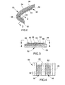
- FIGS. 3 and 4 represent the anti-icing system 60 as comprising multiple heater strips 62 arranged in parallel columns 66.
- the columns 66 of heater strips 62 can be configured to advantageously promote the flexibility of the anti-icing system 60 in planes parallel to the columns 66.
- the columns 66 can be arranged along radials of the nacelle 50 of FIG. 2 , promoting the ability of the anti-icing system 60 to closely conform to the contour of the interior surface 59 of the inlet lip 56.
- the strips 62 within each column 66 are shown as closely spaced and optionally touching each other, though gaps between adjacent strips 62 could be provided.
- the ends of the heater strips 62 are shown as connected by contacts 68 arranged so that, for example, current supplied to the contact 68 between the rows of strips 62 will flow through each strip 62 toward a corresponding one of the outer contacts 68.
- the contacts 68 can be formed in any suitable manner, including but not limited to deposition processes such as electroplating one or more conductive metals or metal alloys. As represented in FIG. 4 , the contacts 68 preferably contact the entire width of each heater strip 62 to maximize the electrical contact and reduce the electrical interface resistance therebetween.
- a coupling mechanism such as a glassy carbon material, may be employed to enhance contact between the contacts 68 and the heater strips 62. In any event, sufficient power can be applied to the heater strips 62 by a suitable power source (not shown) to generate heat by Joule heating, which in turn causes heating of the inlet lip 56 by thermal conduction.
- the anti-icing system 60 includes an electrical insulation layer 64 between the heater strips 62 and interior surface 59 of the nacelle 50 to electrically insulate the nacelle 50 from the current flowing through the heater strips 62. Because heat transfer to the nacelle 50 is through thermal conduction, the insulation layer 64 should be chosen to have a minimal impact on heat transfer (conduction) to the nacelle 50.
- polyamides are a class of polymeric materials that exhibit both electrical insulating properties and appreciable thermal conductivity, though those skilled in the art will be aware of various other potential materials for the insulation layer 64.
- the insulation layer 64 is preferably not more than 0.15 millimeter in thickness, more preferably about 0.05 to about 0.1 millimeter in thickness, such that the heater strips 62 are in close proximity to the nacelle 50.
- the anti-icing system 60 is shown as directly contacting the interior surface 59 of the nacelle 50 as a result of the heater strips 62 directly contacting the insulation layer 64, and the insulation layer 64 directly contacting the interior surface 59 of the nacelle 50.
- the entire anti-icing system 60 can have a relatively thin cross-section, preferably up to typical thicknesses for the nacelle 50, for example, about 3 millimeters or less, and therefore is capable of contributing minimal weight to the nacelle 50.
- a strip of nonwoven textile material having dimensions of about 1 inch by about 8.5 inches by about 0.06 inch (about 2.5 x 22 x 0.15 cm) was formed from carbon nanotubes. Electrical contacts were formed at the longitudinal ends of the strip by attaching thin copper sheets using a conductive adhesive, crimping, or both. The strip was then bonded to a graphite-reinforced epoxy laminate with EPON 862 epoxy adhesive (Shell Chemical Company), with a 0.001 inch (about 25 micrometer) polyamide insulation layer separating the strip from the laminate to prevent electrical shorting. A range of voltages was then applied with a DC power source across the contacts.
- Temperature distribution of the strip-laminate assembly was measured with a thermal imaging camera and found to be generally uniform along the length of the strip (about 97.4°C) and generally parabolic across the width of the laminate, with significant heating occurring in the laminate at distances from the strip of roughly half the width of the strip. From these results, it was concluded that a carbon nanotube strip would be very effective as an anti-icing heater element for a graphite-reinforced epoxy laminate, and could be significantly more efficient than existing heating elements of the prior art.
- FIGS. 5 and 6 represent another embodiment for providing an anti-icing capability in combination with a composite nacelle 70.
- the embodiment of FIGS. 5 and 6 represents an anti-icing system 80 incorporated into the laminate composite structure of the nacelle 70.
- Various aspects of the anti-icing system 80 of FIGS. 5 and 6 can be the same or similar to that described for the anti-icing system 60 of FIGS. 2 through 4 , and as such the following description will focus only on the primary differences between the embodiments of FIGS. 2 through 4 and FIGS. 5 through 6 .
- the laminate construction of the nacelle 70 is represented as being made up of individual laminae 82, 84, and 86 (not to scale) of different compositions.
- all of the laminae 82, 84 and 86 have cross-sectional shapes that conform to the cross-sectional shape of the nacelle 70 in the region of its inlet lip 76.
- the lamina 86 located at the outer surface 78 of the nacelle 70 is preferably formed of a resin-impregnated fabric, such as a graphite-reinforced epoxy lamina.
- the nacelle 70 includes additional laminae 86 similar or identical to the lamina 86 located at the outer surface 78.
- lamina 86 will be referred to as structural lamina 86 to indicate their primary structural role within the nacelle 70.
- Other lamina 82 within the laminate construction of the nacelle 70 will be referred to as heating lamina 82, indicating their primary role as associated with the anti-icing system 80 of FIGS. 5 and 6.
- FIG. 1 A diagrammatic representation of the anti-icing system 80 of FIGS. 5 and 6.
- FIG. 6 represents one of the heating laminae 82 as defining or otherwise located at the interior surface 79 of the nacelle 70, two other heating laminae 82 as entirely within the nacelle 70, and all three heating laminae 82 separated from the structural laminae 86 by a third type of lamina, referred to as an insulation lamina 84 that electrically insulates the heating laminae 82 from their adjacent structural laminae 86.
- an insulation lamina 84 that electrically insulates the heating laminae 82 from their adjacent structural laminae 86.
- the insulation lamina 84 can be formed of a material that exhibits suitably high electrical insulation properties and sufficiently high thermal conductivity at minimal thickness, for example, not more than 0.15 millimeter and more preferably about 0.05 to about 0.1 millimeter, so as not to significantly contribute to the weight of the nacelle 70.
- FIGS. 5 and 6 is not limited to the particular number and arrangement of laminae 82, 84 and 86 shown in FIG. 6 .
- the laminate construction of the nacelle 70 may further contain a core material (not shown), such as a lightweight foam or honeycomb polymeric material, as discussed previously.
- the entire laminate nacelle 70 with its embedded anti-icing system 80 can have a cross-sectional thickness that is slightly greater than would otherwise be required in the absence of the heating laminae 82.
- the heating laminae 82 preferably contain carbon nanotubes and are electrically connected to a suitable power source (not shown) to provide heating of the nacelle 70, or at least those portions of the nacelle 70 that contain the heating laminae 82 and are most susceptible to icing, namely, the inlet lip 76 and portions of the inlet duct 72 and outer barrel 74 just aft of the inlet lip 76.
- the laminae 82 may comprise nonwoven textiles (NWT) or woven textiles (WT) of carbon nanotubes, such as those described in U.S. Published Patent Application No.
- the laminae 82 can be infiltrated with the same epoxy resin matrix material as that used for the structural lamina 86, allowing the laminae 82 and 86 to be co-cured during curing of the laminate construction of the nacelle 70.
- Electrical contacts 88 are schematically represented as pins or probes that project through the layers of the laminate nacelle 70 to make electrical contact with at least the heating lamina 82 located at the interior surface 79 of the nacelle 70, and more preferably to make contact with each of the heating laminae 82 within the laminate construction of the nacelle 70. Sufficient power is applied to the contacts 88 to cause Joule heating of the carbon nanotube material within the heating laminae 82, which in turn causes heating of the inlet lip 76 by thermal conduction.
- FIGS. 5 and 6 has the advantage of placing the heating laminae 82 within the laminate structure of the nacelle 70, and relying on the matrix material of the laminate structure to attach the heating laminae 82 to the nacelle 70.
- the heating laminae 82 are able to more efficiently heat the exterior surface 78 of the nacelle 70 to remove and prevent ice buildup.
- the nacelle 70 should be able to better resist delamination and fatigue fractures as compared to laminate structures in which wire mesh and flexible graphite material (for example, GRAFOIL®) have been incorporated.
- the matrix material of the laminate structure can also be used to provide electrical insulation between the heating laminae 82 and the remaining layers of the structure, further minimizing the additional weight contributed by the anti-icing system 80 to the nacelle 70.
- Other advantages believed to arise from the use of carbon nanotube layers in the laminate structure include greater in-plane and out-of-plane strength, and higher thermal degradation temperatures as compared to prior art heating elements such as wire meshes and flexible graphite materials.
Abstract
Description
- The present invention relates to turbomachinery, and more particularly to anti-icing and de-icing systems for aircraft engine nacelles fabricated at least in part from composite materials.
- High-bypass turbofan engines are widely used for high performance aircraft that operate at subsonic speeds. As schematically represented in
FIG. 1 , a high-bypass turbofan engine 10 includes alarge fan 12 placed at the front of theengine 10 to produce greater thrust and reduce specific fuel consumption. Thefan 12 serves to compressincoming air 14, a portion of which flows into a core engine (gas turbine) 16 that includes acompressor section 18 containing low and highpressure compressor stages combustion chamber 20 where fuel is mixed with the compressed air and combusted, and aturbine section 22 where ahigh pressure turbine 22A extracts energy from the combustion gases to drive thehigh pressure stages 18B of thecompressor section 18 and alow pressure turbine 22B extracts energy from the combustion gases to drive thefan 12 and thelow pressure stages 18A of thecompressor section 18. A larger portion of the air that enters thefan 12 is bypassed to the rear of theengine 10 to generate additional engine thrust. The bypassed air passes through an annular-shaped bypass duct 24 that contains one or more rows of stator vanes, also called outlet guide vanes 28 (OGVs), located immediately aft of thefan 12 and itsfan blades 26. Thefan blades 26 are surrounded by a fan cowling ornacelle 30 that defines theinlet duct 32 to theturbofan engine 10 as well as afan nozzle 34 for the bypassed air exiting thebypass duct 24. - The
nacelle 30 is an important structural component whose design considerations include aerodynamic criteria as well as the ability to withstand foreign object damage (FOD). For these reasons, it is important to select appropriate constructions, materials and assembly methods when manufacturing thenacelle 30. Various materials and configurations have been considered, with metallic materials and particularly aluminum alloys being widely used. Composite materials have also been considered, such as graphite-reinforced epoxy laminates, as they offer advantages including the ability to be fabricated as single-piece parts of sufficient size to meet aerodynamic criteria, contour control, and reduced weight, which promote engine efficiency and improve specific fuel consumption (SFC). - Aircraft engine nacelles are subject to icing conditions, particularly the nacelle leading edge at the inlet lip (36 of
FIG. 1 ) while the engine is on the ground and especially under flight conditions. One well known approach to removing ice buildup (de-icing) and preventing ice buildup (anti-icing) on the nacelle inlet lip has been through the use of hot air bleed systems. An example is schematically represented inFIG. 1 , in which engine-supplied bleed air flow is drawn from thecombustion chamber 20 throughpiping 38 to theinlet lip 36, where the hot bleed air contacts the internal surface of theinlet lip 36 to heat thelip 36 and remove/prevent ice formation. Thepiping 38 includes a tube arrangement commonly referred to as apiccolo tube 40, which resides in an annular-shaped cavity of thenacelle 30 sometimes referred to as the D-duct 42. Thetube 40 completely fills the D-duct 42 with the hot bleed air to ensure adequate heating of theinlet lip 36. While this type of system is effective, it requires a large amount of bleed air to fill the D-duct 42 and provide the thermal energy necessary to perform the anti-icing function. The hot air bled from theengine 10 results in a corresponding negative impact on engine performance and detracts from engine efficiency (SFC). Additionally, hot air bleed systems of the type represented can incur a significant weight penalty. - As an alternative, some smaller turbofans and turboprop aircraft engines have utilized electrical anti-icing systems that convert electrical energy into heat via Joule heating. Resistance-type heater wires can be used as the heating element, though a more recent example uses a flexible graphite material commercially available under the name GRAFOIL® from GrafTech International Holdings Inc. The heating element is embedded in a boot, such as a silicon rubber, which in turn is attached to the inside leading edge of the nacelle inlet lip. A drawback of such systems is that they typically require excessive energy for de-icing and continuous anti-icing operation on large aircraft engines, such as high-bypass turbofan engines of the type represented in
FIG. 1 . Furthermore, electrical anti-icing systems are relatively heavy and detract from engine efficiency/performance. - Still other options include "weeping" systems that release chemical de-icing agents, and de-icing boots equipped with inflatable bladders to crack ice buildup. Notable disadvantages of weeping systems include the high cost of chemical de-icing agents, the requirement that the aircraft carry the de-icing agent at all times, and the inoperability of the system if the supply of chemical agent is exhausted during flight. Disadvantages of de-icing boots include the requirement for a pump to inflate the bladders and a relatively short life span.
- In view of the above, there are ongoing efforts to develop new technologies capable of providing de-icing and anti-icing functions while minimizing any negative impact on weight and power requirements, particularly with regard to the use of nacelles and other airfoil surfaces that are fabricated from composite materials to promote overall engine performance. However, the use of composite materials such as graphite-reinforced epoxy laminates in place of conventional aluminum alloy nacelles and wing structures poses additional challenges to anti-icing systems, since laminate composite materials exhibit relatively poor thermal conductivity in the thickness direction (and therefore between adjacent laminae), reducing the efficiency with which conventional anti-icing systems can heat the outer surfaces of a nacelle to remove and prevent ice buildup.
- The present invention provides a system and method for removing (de-icing) and preventing (anti-icing) ice buildup on aircraft engine nacelles, nonlimiting examples of which are nacelles partially or completely fabricated from composite materials.
- According to a first aspect of the invention, the nacelle has an inlet lip that defines a leading edge of the nacelle and has a cross-sectional shape and oppositely-disposed exterior and interior surfaces. An anti-icing system contacts at least the inlet lip of the nacelle. The anti-icing system comprises at least one heating element having a cross-sectional shape that conforms to the cross-sectional shape of the inlet lip and in which carbon nanotubes are oriented and arranged to conduct electrical current through the heating element. The nacelle further comprises means for passing an electrical current through the heating element to cause Joule heating of the heating element and heating of the inlet lip by thermal conduction.
- According to a second aspect of the invention, the above-described construction provides for a method capable of removing and preventing ice buildup on the inlet lip of a nacelle. Such a method entails fabricating the inlet lip to have a cross-sectional shape and oppositely-disposed exterior and interior surfaces, and contacting at least the inlet lip of the nacelle with an anti-icing system comprising at least one heating element having a cross-sectional shape that conforms to the cross-sectional shape of the inlet lip, and within which carbon nanotubes are oriented and arranged to conduct electrical current through the heating element. The method further entails passing an electrical current through the heating element to cause Joule heating of the heating element and heating of the inlet lip by thermal conduction.
- A technical effect of this invention is the ability to provide an anti-icing system for an aircraft engine nacelle that contributes minimal weight to the engine, while also requiring minimal energy for its operation. Embodiments of the invention are also capable of improving the efficiency with which the exterior surface of the nacelle can be heated to remove and prevent ice buildup.
- Other aspects and advantages of this invention will be better appreciated from the following detailed description.
- There follows a detailed description of embodiments of the invention by way of example only with reference to the accompanying drawings, in which:
-
FIG. 1 schematically represents a cross-sectional view of a high-bypass turbofan engine. -
FIG. 2 is a detailed view showing a cross-section of a nacelle inlet lip of a turbofan engine in accordance with an embodiment of the invention. -
FIG. 3 is a detailed cross-sectional view of the nacelle inlet lip ofFIG. 2 . -
FIG. 4 is a detailed plan view of the nacelle inlet lip ofFIG. 3 . -
FIG. 5 is a detailed view showing a cross-section of a nacelle inlet lip of a turbofan engine in accordance with another embodiment of the invention. -
FIG. 6 is a detailed cross-sectional view of the nacelle inlet lip ofFIG. 5 . -
FIGS. 2 through 6 represent two embodiments of the present invention by which an anti-icing and de-icing capability (hereinafter, simply referred to as anti-icing) is provided in combination with anaircraft engine nacelle turbofan engine 10 represented in FIG. l, though it should be understood that other applications are foreseeable. For convenience, the invention will be described with reference to theengine 10 inFIG. 1 , though modified to some extent by details of the invention described in reference to the embodiments ofFIGS. 2 through 6 . - The
nacelles FIGS. 2 through 6 can be formed of a variety of materials, including such conventional materials as metal alloys and particularly aluminum alloys. However, a preferred aspect of the invention is the ability to produce thenacelles nacelles inlet lips nacelles - According to another preferred aspect of the invention, at least the outer section of the
nacelle inlet lip nacelles inlet lip FIG. 1 ). Suitable methods for producing thenacelles 50 and 70 (or at least those portions formed of a composite material) include resin transfer molding (RTM), compression molding, autoclave curing, and vacuum-assisted resin transfer molding (VaRTM), which are well known for producing resin-impregnated laminate composite structures. Finally, it is within the scope of the invention to incorporate a core material (not shown), such as a lightweight foam or honeycomb polymeric material, within the laminate structure of thenacelles - In view of the materials noted above, the
nacelles nacelles - As noted above, a particular aspect of the invention is to provide an anti-icing capability in combination with a composite nacelle of the type described above. With reference to
FIG. 2 , a cross-section of thenacelle 50 represents a first embodiment of the invention. As with theprior art nacelle 30 represented inFIG. 1 , thenacelle 50 defines aninlet duct 52,outer barrel 54 andinlet lip 56 of the turbofan engine, as well as the bypass duct and fan nozzle (not shown inFIG. 2 ) through which bypassed air flows. As previously discussed, thenacelle 50 and more specifically itsouter surface 58 is subject to icing conditions while the engine is on the ground and under flight conditions. The embodiment ofFIG. 2 employs ananti-icing system 60 that includes heater strips 62 configured to provide localized heating of that portion of thenacelle 50 most susceptible to icing, namely, theexterior surface 58 at theinlet lip 56 and portions of theinlet duct 52 andouter barrel 54 just aft of theinlet lip 56. Theanti-icing system 60 can be configured to have an annular shape corresponding to the shape of the nacelle 50 (as evident fromFIG. 1 ). As represented inFIG. 2 , thesystem 60 has a U-shaped cross-section closely conforming to theinterior surface 59 of thenacelle 50 in the vicinity of theinlet lip 56 and adjacent portions of theinlet duct 52 andouter barrel 54. - According to a preferred aspect of the invention, the heater strips 62 comprise carbon nanotubes (CNTs), and more preferably a nonwoven textile (NWT) or woven textile (WT) of carbon nanotubes, such that each
strip 62 is a unitary mat that can be handled, encapsulated or infiltrated, and bonded to theinterior surface 59 of thenacelle 50. Importantly, the nanotubes are not randomly dispersed within the heater strips 62, but instead are deliberately oriented and arranged within eachstrip 62 to ensure contact each other and enable the nanotubes to conduct electrical current, for example, in the lengthwise and/or widthwise directions of eachstrip 62. A particularly suitable nonwoven textile of carbon nanotubes has been developed by Nanocomp Technologies, Inc., of Concord, New Hampshire, and is described inU.S. Published Patent Application No. 2009/0277897 to Lashmore et al. The contents of this published application relating to the composition, structure and fabrication of carbon nanotubes and textiles formed thereof are incorporated herein by reference. As reported in Lashmore et al., the carbon nanotubes can be single wall (S WNT), double wall (DWNT), or multiwall (MWNT), and individual carbon nanotubes can be produced and used in a range of diameters, for example, less than one nanometer to about ten nanometers, and a range of lengths, for example, up to about one millimeter or more. Lashmore et al. also report that sheets of nonwoven carbon nanotubes (and presumably woven carbon nanotubes) may be coated or infiltrated with a resin material, a nonlimiting example being furfuryl alcohol (C4H3OCH2OH), using various known techniques to bond the nanotubes and optionally fill voids between nanotubes. According to the present invention, another possible coating/infiltrant is the resin used to form the matrix of thelaminate nacelle 50. Carbon nanotube-based materials of the type described above are said to be capable of more efficiently generating heat than conventional resistive-heating materials such as copper wires, and can be utilized at higher power and voltage levels than copper wires having substantially equivalent mass or cross-sectional area, such that the heater strips 62 are capable of increased efficiency and greater thermal output. -
FIGS. 3 and 4 represent theanti-icing system 60 as comprising multiple heater strips 62 arranged inparallel columns 66. Thecolumns 66 of heater strips 62 can be configured to advantageously promote the flexibility of theanti-icing system 60 in planes parallel to thecolumns 66. As depicted inFIG. 2 , thecolumns 66 can be arranged along radials of thenacelle 50 ofFIG. 2 , promoting the ability of theanti-icing system 60 to closely conform to the contour of theinterior surface 59 of theinlet lip 56. Thestrips 62 within eachcolumn 66 are shown as closely spaced and optionally touching each other, though gaps betweenadjacent strips 62 could be provided. The ends of the heater strips 62 are shown as connected bycontacts 68 arranged so that, for example, current supplied to thecontact 68 between the rows ofstrips 62 will flow through eachstrip 62 toward a corresponding one of theouter contacts 68. Thecontacts 68 can be formed in any suitable manner, including but not limited to deposition processes such as electroplating one or more conductive metals or metal alloys. As represented inFIG. 4 , thecontacts 68 preferably contact the entire width of eachheater strip 62 to maximize the electrical contact and reduce the electrical interface resistance therebetween. To promote electrical contact between thecontacts 68 and the heater strips 62, Lashmore et al. suggest that a coupling mechanism, such as a glassy carbon material, may be employed to enhance contact between thecontacts 68 and the heater strips 62. In any event, sufficient power can be applied to the heater strips 62 by a suitable power source (not shown) to generate heat by Joule heating, which in turn causes heating of theinlet lip 56 by thermal conduction. - As represented in
FIGS. 2 and 3 , theanti-icing system 60 includes anelectrical insulation layer 64 between the heater strips 62 andinterior surface 59 of thenacelle 50 to electrically insulate thenacelle 50 from the current flowing through the heater strips 62. Because heat transfer to thenacelle 50 is through thermal conduction, theinsulation layer 64 should be chosen to have a minimal impact on heat transfer (conduction) to thenacelle 50. As a nonlimiting example, polyamides are a class of polymeric materials that exhibit both electrical insulating properties and appreciable thermal conductivity, though those skilled in the art will be aware of various other potential materials for theinsulation layer 64. Theinsulation layer 64 is preferably not more than 0.15 millimeter in thickness, more preferably about 0.05 to about 0.1 millimeter in thickness, such that the heater strips 62 are in close proximity to thenacelle 50. Theanti-icing system 60 is shown as directly contacting theinterior surface 59 of thenacelle 50 as a result of the heater strips 62 directly contacting theinsulation layer 64, and theinsulation layer 64 directly contacting theinterior surface 59 of thenacelle 50. - Various techniques may be employed to attach or otherwise mount the
anti-icing system 60 to theinterior surface 59 of thenacelle 50. A preferred method is to apply a thin layer of a thermally conductive adhesive, though other methods are also within the scope of the invention. The entireanti-icing system 60 can have a relatively thin cross-section, preferably up to typical thicknesses for thenacelle 50, for example, about 3 millimeters or less, and therefore is capable of contributing minimal weight to thenacelle 50. - In an investigation leading to the present invention, a strip of nonwoven textile material having dimensions of about 1 inch by about 8.5 inches by about 0.06 inch (about 2.5 x 22 x 0.15 cm) was formed from carbon nanotubes. Electrical contacts were formed at the longitudinal ends of the strip by attaching thin copper sheets using a conductive adhesive, crimping, or both. The strip was then bonded to a graphite-reinforced epoxy laminate with EPON 862 epoxy adhesive (Shell Chemical Company), with a 0.001 inch (about 25 micrometer) polyamide insulation layer separating the strip from the laminate to prevent electrical shorting. A range of voltages was then applied with a DC power source across the contacts. Temperature distribution of the strip-laminate assembly was measured with a thermal imaging camera and found to be generally uniform along the length of the strip (about 97.4°C) and generally parabolic across the width of the laminate, with significant heating occurring in the laminate at distances from the strip of roughly half the width of the strip. From these results, it was concluded that a carbon nanotube strip would be very effective as an anti-icing heater element for a graphite-reinforced epoxy laminate, and could be significantly more efficient than existing heating elements of the prior art.
-
FIGS. 5 and 6 represent another embodiment for providing an anti-icing capability in combination with acomposite nacelle 70. In contrast to the separateanti-icing system 60 ofFIG. 2 , the embodiment ofFIGS. 5 and 6 represents ananti-icing system 80 incorporated into the laminate composite structure of thenacelle 70. Various aspects of theanti-icing system 80 ofFIGS. 5 and 6 can be the same or similar to that described for theanti-icing system 60 ofFIGS. 2 through 4 , and as such the following description will focus only on the primary differences between the embodiments ofFIGS. 2 through 4 andFIGS. 5 through 6 . - In contrast to
FIG. 2 , the laminate construction of thenacelle 70 is represented as being made up ofindividual laminae nacelle 70, all of thelaminae nacelle 70 in the region of itsinlet lip 76. Thelamina 86 located at theouter surface 78 of thenacelle 70 is preferably formed of a resin-impregnated fabric, such as a graphite-reinforced epoxy lamina. Thenacelle 70 includesadditional laminae 86 similar or identical to thelamina 86 located at theouter surface 78. Theselamina 86 will be referred to asstructural lamina 86 to indicate their primary structural role within thenacelle 70.Other lamina 82 within the laminate construction of thenacelle 70 will be referred to asheating lamina 82, indicating their primary role as associated with theanti-icing system 80 ofFIGS. 5 and 6. FIG. 6 represents one of theheating laminae 82 as defining or otherwise located at theinterior surface 79 of thenacelle 70, twoother heating laminae 82 as entirely within thenacelle 70, and all threeheating laminae 82 separated from thestructural laminae 86 by a third type of lamina, referred to as aninsulation lamina 84 that electrically insulates theheating laminae 82 from their adjacentstructural laminae 86. As with theinsulation layer 64 in the embodiment ofFIGS. 2 through 4 , theinsulation lamina 84 can be formed of a material that exhibits suitably high electrical insulation properties and sufficiently high thermal conductivity at minimal thickness, for example, not more than 0.15 millimeter and more preferably about 0.05 to about 0.1 millimeter, so as not to significantly contribute to the weight of thenacelle 70. - It should be understood that the embodiment of
FIGS. 5 and 6 is not limited to the particular number and arrangement oflaminae FIG. 6 . Furthermore, as with the first embodiment, the laminate construction of thenacelle 70 may further contain a core material (not shown), such as a lightweight foam or honeycomb polymeric material, as discussed previously. Theentire laminate nacelle 70 with its embeddedanti-icing system 80 can have a cross-sectional thickness that is slightly greater than would otherwise be required in the absence of theheating laminae 82. - As with the heating strips 62 used in the embodiment of
FIGS. 2 through 4 , theheating laminae 82 preferably contain carbon nanotubes and are electrically connected to a suitable power source (not shown) to provide heating of thenacelle 70, or at least those portions of thenacelle 70 that contain theheating laminae 82 and are most susceptible to icing, namely, theinlet lip 76 and portions of theinlet duct 72 andouter barrel 74 just aft of theinlet lip 76. Also consistent with the previous embodiment, thelaminae 82 may comprise nonwoven textiles (NWT) or woven textiles (WT) of carbon nanotubes, such as those described inU.S. Published Patent Application No. 2009/0277897 to Lashmore et al. Thelaminae 82 can be infiltrated with the same epoxy resin matrix material as that used for thestructural lamina 86, allowing thelaminae nacelle 70.Electrical contacts 88 are schematically represented as pins or probes that project through the layers of thelaminate nacelle 70 to make electrical contact with at least theheating lamina 82 located at theinterior surface 79 of thenacelle 70, and more preferably to make contact with each of theheating laminae 82 within the laminate construction of thenacelle 70. Sufficient power is applied to thecontacts 88 to cause Joule heating of the carbon nanotube material within theheating laminae 82, which in turn causes heating of theinlet lip 76 by thermal conduction. - The embodiment of
FIGS. 5 and 6 has the advantage of placing theheating laminae 82 within the laminate structure of thenacelle 70, and relying on the matrix material of the laminate structure to attach theheating laminae 82 to thenacelle 70. As a result, theheating laminae 82 are able to more efficiently heat theexterior surface 78 of thenacelle 70 to remove and prevent ice buildup. Furthermore, thenacelle 70 should be able to better resist delamination and fatigue fractures as compared to laminate structures in which wire mesh and flexible graphite material (for example, GRAFOIL®) have been incorporated. The matrix material of the laminate structure can also be used to provide electrical insulation between theheating laminae 82 and the remaining layers of the structure, further minimizing the additional weight contributed by theanti-icing system 80 to thenacelle 70. Other advantages believed to arise from the use of carbon nanotube layers in the laminate structure include greater in-plane and out-of-plane strength, and higher thermal degradation temperatures as compared to prior art heating elements such as wire meshes and flexible graphite materials. - While the invention has been described in terms of specific embodiments, other forms could be adopted by one skilled in the art. For example, the physical configuration of the
turbofan engine 10 andnacelles - Various aspects and embodiments of the present invention are defined by the following numbered clauses:
- 1. A nacelle for installation at an inlet to an aircraft engine, the nacelle comprising:
- an inlet lip defining a leading edge of the nacelle and having a cross-sectional shape and oppositely-disposed exterior and interior surfaces;
- an anti-icing system contacting at least the inlet lip of the nacelle, the anti-icing system comprising at least one heating element having a cross-sectional shape that conforms to the cross-sectional shape of the inlet lip, the heating element comprising carbon nanotubes oriented and arranged to conduct electrical current through the heating element; and
- means for passing an electrical current through the heating element to cause Joule heating of the heating element and heating of the inlet lip by thermal conduction.
- 2. The nacelle according to clause l, wherein the heating element is adjacent the interior surface of the inlet lip to cause heating of the interior surface by thermal conduction.
- 3. The nacelle according to clause 2, wherein the heating element conforms to the interior surface of the inlet lip.
- 4. The nacelle according to clause 2, further comprising an insulation layer that separates the heating element from the interior surface of the inlet lip.
- 5. The nacelle according to clause 2, wherein the nacelle comprises a plurality of the heating element, and the heating elements are arranged in parallel columns.
- 6. The nacelle according to clause 5, wherein the parallel columns of the heating elements are oriented to promote flexing of the anti-icing system in a plane parallel to the columns .
- 7. The nacelle according to clause 5, wherein the parallel columns of the heating elements are oriented along radials of the nacelle.
- 8. The nacelle according to clause 1, wherein at least the inlet lip of the nacelle has a laminate construction.
- 9. The nacelle according to clause 8, wherein the heating element is embedded within the laminate construction of the inlet lip.
- 10. The nacelle according to clause 8, wherein the heating element defines the interior surface of the inlet lip.
- 11. The nacelle according to
clause 10, further comprising an insulation layer that separates the heating element from other portions of the laminate construction of the inlet lip. - 12. The nacelle according to clause 1, wherein the carbon nanotubes have diameters of up to about ten nanometers.
- 13. The nacelle according to clause 1, wherein the heating element further comprises an matrix material that infiltrates the carbon nanotubes.
- 14. The nacelle according to clause 13, wherein at least the inlet lip of the nacelle has a laminate construction comprising a reinforcement material infiltrated by a matrix material, and the matrix materials of the heating element and the laminate construction are the same.
- 15. The nacelle according to clause 1, wherein the nacelle is installed in the aircraft engine and surrounds a fan of the aircraft engine.
- 16. The nacelle according to clause 15, wherein the aircraft engine is a high-bypass gas turbine engine and the nacelle surrounds a high-bypass duct of the aircraft engine.
- 17. A method of removing and preventing ice buildup on an inlet lip that defines a leading edge of a nacelle of an aircraft engine, the method comprising:
- fabricating the inlet lip to have a cross-sectional shape and oppositely-disposed exterior and interior surfaces;
- contacting at least the inlet lip of the nacelle with an anti-icing system comprising at least one heating element having a cross-sectional shape that conforms to the cross-sectional shape of the inlet lip, the heating element comprising carbon nanotubes oriented and arranged to conduct electrical current through the heating element; and
- passing an electrical current through the heating element to cause Joule heating of the heating element and heating of the inlet lip by thermal conduction.
- 18. The method according to clause 17, further comprising forming at least the inlet lip of the nacelle of a composite material, and locating the heating element adjacent the interior surface of the inlet lip to cause heating of the interior surface by thermal conduction.
- 19. The method according to clause 17, further comprising forming at least the inlet lip of the nacelle to have a laminate construction, and embedding the heating element within the laminate construction.
- 20. The method according to clause 17, further comprising installing the nacelle in the aircraft engine.
Claims (15)
- A nacelle (50,70) for installation at an inlet to an aircraft engine (10), the nacelle (50,70) comprising an inlet lip (56,76) defining a leading edge of the nacelle (50,70) and having a cross-sectional shape and oppositely-disposed exterior and interior surfaces (58/78,59/79), characterized by:an anti-icing system (60,80) contacting at least the inlet lip (56,76) of the nacelle (50,70), the anti-icing system (60,80) comprising at least one heating element (62,82) having a cross-sectional shape that conforms to the cross-sectional shape of the inlet lip (56,76), the heating element (62,82) comprising carbon nanotubes oriented and arranged to conduct electrical current through the heating element (62,82); andmeans (68,88) for passing an electrical current through the heating element (62,82) to cause Joule heating of the heating element (62,82) and heating of the inlet lip (56,76) by thermal conduction.
- The nacelle (50,70) according to any one of claim 1, characterized in that at least the inlet lip (56,76) of the nacelle (50,70) has a laminate construction.
- The nacelle (50) according to claim 1 or 2, characterized in that the heating element (62) is adjacent the interior surface (59) of the inlet lip (56) to cause heating of the interior surface (59) by thermal conduction.
- The nacelle according to claim 3, wherein the heating element conforms to the interior surface of the inlet lip.
- The nacelle (50) according to claim 3, further characterized by an insulation layer (64) that separates the heating element (62) from the interior surface (59) of the inlet lip (56).
- The nacelle (50) according to any of claims 3 to 5, characterized in that the nacelle (50) comprises a plurality of the heating element (62), and the heating elements (62) are arranged in parallel columns (66).
- The nacelle (50) according to claim 6, characterized in that the parallel columns (66) of the heating elements (62) are oriented to promote flexing of the anti-icing system (60) in a plane parallel to the columns (66).
- The nacelle according to clause 6, wherein the parallel columns of the heating elements are oriented along radials of the nacelle.
- The nacelle (70) according to claim 2, characterized in that the heating element (82) is embedded within the laminate construction of the inlet lip (56,76).
- The nacelle (70) according to claim 9, further characterized by an insulation layer (84) that separates the heating element (82) from other portions of the laminate construction of the inlet lip (76).
- The nacelle (50,70) according to any one of claims 1 to 10, characterized in that the nacelle (50,70) is installed in the aircraft engine (10) and surrounds a fan (26) of the aircraft engine (10).
- A method of removing and preventing ice buildup on an inlet lip (56,76) that has a cross-sectional shape and oppositely-disposed exterior and interior surfaces (58/78,59/79) and defines a leading edge of a nacelle (50,70) of an aircraft engine (10), the method characterized by:contacting at least the inlet lip (56,76) of the nacelle (50,70) with an anti-icing system (60,80) comprising at least one heating element (62,82) having a cross-sectional shape that conforms to the cross-sectional shape of the inlet lip (56,76), the heating element (62,82) comprising carbon nanotubes oriented and arranged to conduct electrical current through the heating element (62,82); andpassing an electrical current through the heating element (62,82) to cause Joule heating of the heating element (62,82) and heating of the inlet lip (56,76) by thermal conduction.
- The method according to claim 12, further comprising forming at least the inlet lip of the nacelle of a composite material, and locating the heating element adjacent the interior surface of the inlet lip to cause heating of the interior surface by thermal conduction.
- The method according to claim 12, further comprising forming at least the inlet lip of the nacelle to have a laminate construction, and embedding the heating element within the laminate construction.
- The method according to any of claims 12 to 14, further comprising installing the nacelle in the aircraft engine.
Applications Claiming Priority (1)
| Application Number | Priority Date | Filing Date | Title |
|---|---|---|---|
| US12/649,387 US8549832B2 (en) | 2009-12-30 | 2009-12-30 | Turbomachine nacelle and anti-icing system and method therefor |
Publications (3)
| Publication Number | Publication Date |
|---|---|
| EP2354469A2 true EP2354469A2 (en) | 2011-08-10 |
| EP2354469A3 EP2354469A3 (en) | 2014-01-22 |
| EP2354469B1 EP2354469B1 (en) | 2018-02-21 |
Family
ID=43640546
Family Applications (1)
| Application Number | Title | Priority Date | Filing Date |
|---|---|---|---|
| EP10195197.8A Active EP2354469B1 (en) | 2009-12-30 | 2010-12-15 | Turbomachine Nacelle And Anti-Icing System And Method Therefor |
Country Status (4)
| Country | Link |
|---|---|
| US (1) | US8549832B2 (en) |
| EP (1) | EP2354469B1 (en) |
| JP (1) | JP5933919B2 (en) |
| CA (1) | CA2725891C (en) |
Families Citing this family (20)
| Publication number | Priority date | Publication date | Assignee | Title |
|---|---|---|---|---|
| WO2011096851A1 (en) * | 2010-01-14 | 2011-08-11 | Saab Ab | Multifunctional de-icing/anti-icing system of a wind turbine |
| CA2786838C (en) * | 2010-01-14 | 2017-01-10 | Saab Ab | Multifunctional de-icing/anti-icing system |
| FR2966801B1 (en) * | 2010-10-29 | 2012-11-02 | Aircelle Sa | ATTACK EDGE STRUCTURE, IN PARTICULAR FOR AN AIRCRAFT ENGINE NACELLE AIR INTAKE |
| GB2498006B (en) * | 2011-12-22 | 2014-07-09 | Rolls Royce Plc | Gas turbine engine systems |
| US9193466B2 (en) * | 2012-07-13 | 2015-11-24 | Mra Systems, Inc. | Aircraft ice protection system and method |
| GB2513652A (en) * | 2013-05-03 | 2014-11-05 | Rolls Royce Plc | Vehicle composite structure |
| EP3017151A1 (en) * | 2013-06-28 | 2016-05-11 | General Electric Company | Flow surface |
| US20160153287A1 (en) * | 2013-07-09 | 2016-06-02 | United Technologies Corporation | Plated polymer turbine component |
| EP3130196A4 (en) | 2014-04-10 | 2017-12-06 | Metis Design Corporation | Multifunctional assemblies |
| WO2016003339A1 (en) * | 2014-07-03 | 2016-01-07 | Saab Ab | A composite article having multifunctional properties and method for its manufacture |
| US20180086470A1 (en) * | 2015-03-06 | 2018-03-29 | Sikorsky Aircraft Corporation | Heating design for rotorcraft blade de-icing and anti-icing |
| ITUB20151085A1 (en) * | 2015-05-28 | 2016-11-28 | Alenia Aermacchi Spa | Nacelle for aircraft engine with de-icing system using a two-phase fluid. |
| US10823060B2 (en) * | 2015-12-18 | 2020-11-03 | Raytheon Technologies Corporation | Gas turbine engine with short inlet, acoustic treatment and anti-icing features |
| US10752999B2 (en) | 2016-04-18 | 2020-08-25 | Rolls-Royce Corporation | High strength aerospace components |
| US10486379B2 (en) | 2016-12-08 | 2019-11-26 | Goodrich Corporation | Reducing CNT resistivity by aligning CNT particles in films |
| FR3061132B1 (en) * | 2016-12-27 | 2023-11-03 | Airbus Operations Sas | STRUCTURE FOR AIRCRAFT PROPULSIVE ASSEMBLY, ASSOCIATED SYSTEM AND PROPULSION ASSEMBLY |
| US10494107B2 (en) * | 2017-01-03 | 2019-12-03 | Goodrich Corporation | Additive manufacturing of conformal deicing and boundary layer control surface for aircraft |
| US11242150B2 (en) * | 2018-06-22 | 2022-02-08 | General Electric Company | Anti-icing system for an aircraft |
| US11261787B2 (en) | 2018-06-22 | 2022-03-01 | General Electric Company | Aircraft anti-icing system |
| FR3084648B1 (en) * | 2018-08-03 | 2020-07-17 | Safran Nacelles | TREATMENT PROCESS AGAINST FROZEN AIRCRAFT PARTS |
Citations (1)
| Publication number | Priority date | Publication date | Assignee | Title |
|---|---|---|---|---|
| US20090277897A1 (en) | 2008-05-07 | 2009-11-12 | Nanocomp Technologies, Inc. | Nanostructure-based heating devices and methods of use |
Family Cites Families (11)
| Publication number | Priority date | Publication date | Assignee | Title |
|---|---|---|---|---|
| WO1995015670A1 (en) * | 1993-11-30 | 1995-06-08 | Alliedsignal Inc. | An electrically conductive composite heater and method of manufacture |
| US6279856B1 (en) * | 1997-09-22 | 2001-08-28 | Northcoast Technologies | Aircraft de-icing system |
| US5934617A (en) * | 1997-09-22 | 1999-08-10 | Northcoast Technologies | De-ice and anti-ice system and method for aircraft surfaces |
| KR100799779B1 (en) * | 2002-02-11 | 2008-01-31 | 더 트러스티즈 오브 다트마우스 칼리지 | Systems and methods for modifying an ice-to-object interface |
| US6732502B2 (en) * | 2002-03-01 | 2004-05-11 | General Electric Company | Counter rotating aircraft gas turbine engine with high overall pressure ratio compressor |
| AU2003218335A1 (en) * | 2002-03-20 | 2003-10-08 | The Trustees Of The University Of Pennsylvania | Nanostructure composites |
| CA2611656C (en) * | 2005-06-22 | 2014-01-07 | Airbus France | Anti-icing and deicing system for aircraft engine pod with resistive mat |
| US7923668B2 (en) * | 2006-02-24 | 2011-04-12 | Rohr, Inc. | Acoustic nacelle inlet lip having composite construction and an integral electric ice protection heater disposed therein |
| US8049147B2 (en) * | 2008-03-28 | 2011-11-01 | United Technologies Corporation | Engine inlet ice protection system with power control by zone |
| GB0805640D0 (en) * | 2008-03-28 | 2008-04-30 | Hexcel Composites Ltd | Improved composite materials |
| JP2009298198A (en) * | 2008-06-10 | 2009-12-24 | Shinmaywa Industries Ltd | Ice prevention/removal device |
-
2009
- 2009-12-30 US US12/649,387 patent/US8549832B2/en active Active
-
2010
- 2010-12-15 EP EP10195197.8A patent/EP2354469B1/en active Active
- 2010-12-16 CA CA2725891A patent/CA2725891C/en active Active
- 2010-12-22 JP JP2010285392A patent/JP5933919B2/en active Active
Patent Citations (1)
| Publication number | Priority date | Publication date | Assignee | Title |
|---|---|---|---|---|
| US20090277897A1 (en) | 2008-05-07 | 2009-11-12 | Nanocomp Technologies, Inc. | Nanostructure-based heating devices and methods of use |
Also Published As
| Publication number | Publication date |
|---|---|
| CA2725891C (en) | 2018-01-09 |
| EP2354469B1 (en) | 2018-02-21 |
| US20110167781A1 (en) | 2011-07-14 |
| JP2011137465A (en) | 2011-07-14 |
| CA2725891A1 (en) | 2011-06-30 |
| US8549832B2 (en) | 2013-10-08 |
| EP2354469A3 (en) | 2014-01-22 |
| JP5933919B2 (en) | 2016-06-15 |
Similar Documents
| Publication | Publication Date | Title |
|---|---|---|
| EP2354469B1 (en) | Turbomachine Nacelle And Anti-Icing System And Method Therefor | |
| CA2725696C (en) | Turbomachine nacelle and anti-icing system and method therefor | |
| US9309001B2 (en) | Aircraft ice protection system and method | |
| JP4293599B2 (en) | Internal anti-icing device for turbofan engine | |
| US9004407B2 (en) | Anti-icing system and method for preventing ice accumulation | |
| EP2529923B1 (en) | Polymer composite materials and processes therefor | |
| US9771866B2 (en) | High temperature composite inlet | |
| US20110005188A1 (en) | Air intake lip for turbojet nacelle | |
| US11261787B2 (en) | Aircraft anti-icing system | |
| CN110626509A (en) | Anti-icing system for aircraft | |
| US11371433B2 (en) | Composite components having piezoelectric fibers | |
| GB2544585A (en) | Heating system for electrothermal temperature control, and method for the production of said heating system |
Legal Events
| Date | Code | Title | Description |
|---|---|---|---|
| PUAI | Public reference made under article 153(3) epc to a published international application that has entered the european phase |
Free format text: ORIGINAL CODE: 0009012 |
|
| AK | Designated contracting states |
Kind code of ref document: A2 Designated state(s): AL AT BE BG CH CY CZ DE DK EE ES FI FR GB GR HR HU IE IS IT LI LT LU LV MC MK MT NL NO PL PT RO RS SE SI SK SM TR |
|
| AX | Request for extension of the european patent |
Extension state: BA ME |
|
| PUAL | Search report despatched |
Free format text: ORIGINAL CODE: 0009013 |
|
| AK | Designated contracting states |
Kind code of ref document: A3 Designated state(s): AL AT BE BG CH CY CZ DE DK EE ES FI FR GB GR HR HU IE IS IT LI LT LU LV MC MK MT NL NO PL PT RO RS SE SI SK SM TR |
|
| AX | Request for extension of the european patent |
Extension state: BA ME |
|
| RIC1 | Information provided on ipc code assigned before grant |
Ipc: F02C 7/047 20060101ALI20131216BHEP Ipc: F01D 17/20 20060101AFI20131216BHEP |
|
| 17P | Request for examination filed |
Effective date: 20140722 |
|
| RBV | Designated contracting states (corrected) |
Designated state(s): AL AT BE BG CH CY CZ DE DK EE ES FI FR GB GR HR HU IE IS IT LI LT LU LV MC MK MT NL NO PL PT RO RS SE SI SK SM TR |
|
| RAP1 | Party data changed (applicant data changed or rights of an application transferred) |
Owner name: MRA SYSTEMS, LLC |
|
| REG | Reference to a national code |
Ref country code: DE Ref legal event code: R079 Ref document number: 602010048589 Country of ref document: DE Free format text: PREVIOUS MAIN CLASS: F01D0017200000 Ipc: B64D0015120000 |
|
| RIC1 | Information provided on ipc code assigned before grant |
Ipc: F02C 7/047 20060101ALI20170710BHEP Ipc: B64D 33/02 20060101ALI20170710BHEP Ipc: B64D 15/12 20060101AFI20170710BHEP |
|
| GRAP | Despatch of communication of intention to grant a patent |
Free format text: ORIGINAL CODE: EPIDOSNIGR1 |
|
| INTG | Intention to grant announced |
Effective date: 20170926 |
|
| GRAS | Grant fee paid |
Free format text: ORIGINAL CODE: EPIDOSNIGR3 |
|
| GRAA | (expected) grant |
Free format text: ORIGINAL CODE: 0009210 |
|
| AK | Designated contracting states |
Kind code of ref document: B1 Designated state(s): AL AT BE BG CH CY CZ DE DK EE ES FI FR GB GR HR HU IE IS IT LI LT LU LV MC MK MT NL NO PL PT RO RS SE SI SK SM TR |
|
| REG | Reference to a national code |
Ref country code: GB Ref legal event code: FG4D |
|
| REG | Reference to a national code |
Ref country code: CH Ref legal event code: EP |
|
| REG | Reference to a national code |
Ref country code: AT Ref legal event code: REF Ref document number: 971423 Country of ref document: AT Kind code of ref document: T Effective date: 20180315 |
|
| REG | Reference to a national code |
Ref country code: IE Ref legal event code: FG4D |
|
| REG | Reference to a national code |
Ref country code: DE Ref legal event code: R096 Ref document number: 602010048589 Country of ref document: DE |
|
| REG | Reference to a national code |
Ref country code: NL Ref legal event code: MP Effective date: 20180221 |
|
| REG | Reference to a national code |
Ref country code: LT Ref legal event code: MG4D |
|
| REG | Reference to a national code |
Ref country code: AT Ref legal event code: MK05 Ref document number: 971423 Country of ref document: AT Kind code of ref document: T Effective date: 20180221 |
|
| PG25 | Lapsed in a contracting state [announced via postgrant information from national office to epo] |
Ref country code: LT Free format text: LAPSE BECAUSE OF FAILURE TO SUBMIT A TRANSLATION OF THE DESCRIPTION OR TO PAY THE FEE WITHIN THE PRESCRIBED TIME-LIMIT Effective date: 20180221 Ref country code: HR Free format text: LAPSE BECAUSE OF FAILURE TO SUBMIT A TRANSLATION OF THE DESCRIPTION OR TO PAY THE FEE WITHIN THE PRESCRIBED TIME-LIMIT Effective date: 20180221 Ref country code: NL Free format text: LAPSE BECAUSE OF FAILURE TO SUBMIT A TRANSLATION OF THE DESCRIPTION OR TO PAY THE FEE WITHIN THE PRESCRIBED TIME-LIMIT Effective date: 20180221 Ref country code: FI Free format text: LAPSE BECAUSE OF FAILURE TO SUBMIT A TRANSLATION OF THE DESCRIPTION OR TO PAY THE FEE WITHIN THE PRESCRIBED TIME-LIMIT Effective date: 20180221 Ref country code: NO Free format text: LAPSE BECAUSE OF FAILURE TO SUBMIT A TRANSLATION OF THE DESCRIPTION OR TO PAY THE FEE WITHIN THE PRESCRIBED TIME-LIMIT Effective date: 20180521 Ref country code: ES Free format text: LAPSE BECAUSE OF FAILURE TO SUBMIT A TRANSLATION OF THE DESCRIPTION OR TO PAY THE FEE WITHIN THE PRESCRIBED TIME-LIMIT Effective date: 20180221 Ref country code: CY Free format text: LAPSE BECAUSE OF FAILURE TO SUBMIT A TRANSLATION OF THE DESCRIPTION OR TO PAY THE FEE WITHIN THE PRESCRIBED TIME-LIMIT Effective date: 20180221 |
|
| PG25 | Lapsed in a contracting state [announced via postgrant information from national office to epo] |
Ref country code: AT Free format text: LAPSE BECAUSE OF FAILURE TO SUBMIT A TRANSLATION OF THE DESCRIPTION OR TO PAY THE FEE WITHIN THE PRESCRIBED TIME-LIMIT Effective date: 20180221 Ref country code: RS Free format text: LAPSE BECAUSE OF FAILURE TO SUBMIT A TRANSLATION OF THE DESCRIPTION OR TO PAY THE FEE WITHIN THE PRESCRIBED TIME-LIMIT Effective date: 20180221 Ref country code: GR Free format text: LAPSE BECAUSE OF FAILURE TO SUBMIT A TRANSLATION OF THE DESCRIPTION OR TO PAY THE FEE WITHIN THE PRESCRIBED TIME-LIMIT Effective date: 20180522 Ref country code: LV Free format text: LAPSE BECAUSE OF FAILURE TO SUBMIT A TRANSLATION OF THE DESCRIPTION OR TO PAY THE FEE WITHIN THE PRESCRIBED TIME-LIMIT Effective date: 20180221 Ref country code: SE Free format text: LAPSE BECAUSE OF FAILURE TO SUBMIT A TRANSLATION OF THE DESCRIPTION OR TO PAY THE FEE WITHIN THE PRESCRIBED TIME-LIMIT Effective date: 20180221 Ref country code: BG Free format text: LAPSE BECAUSE OF FAILURE TO SUBMIT A TRANSLATION OF THE DESCRIPTION OR TO PAY THE FEE WITHIN THE PRESCRIBED TIME-LIMIT Effective date: 20180521 |
|
| PG25 | Lapsed in a contracting state [announced via postgrant information from national office to epo] |
Ref country code: AL Free format text: LAPSE BECAUSE OF FAILURE TO SUBMIT A TRANSLATION OF THE DESCRIPTION OR TO PAY THE FEE WITHIN THE PRESCRIBED TIME-LIMIT Effective date: 20180221 Ref country code: EE Free format text: LAPSE BECAUSE OF FAILURE TO SUBMIT A TRANSLATION OF THE DESCRIPTION OR TO PAY THE FEE WITHIN THE PRESCRIBED TIME-LIMIT Effective date: 20180221 Ref country code: RO Free format text: LAPSE BECAUSE OF FAILURE TO SUBMIT A TRANSLATION OF THE DESCRIPTION OR TO PAY THE FEE WITHIN THE PRESCRIBED TIME-LIMIT Effective date: 20180221 Ref country code: PL Free format text: LAPSE BECAUSE OF FAILURE TO SUBMIT A TRANSLATION OF THE DESCRIPTION OR TO PAY THE FEE WITHIN THE PRESCRIBED TIME-LIMIT Effective date: 20180221 |
|
| REG | Reference to a national code |
Ref country code: DE Ref legal event code: R097 Ref document number: 602010048589 Country of ref document: DE |
|
| PG25 | Lapsed in a contracting state [announced via postgrant information from national office to epo] |
Ref country code: SK Free format text: LAPSE BECAUSE OF FAILURE TO SUBMIT A TRANSLATION OF THE DESCRIPTION OR TO PAY THE FEE WITHIN THE PRESCRIBED TIME-LIMIT Effective date: 20180221 Ref country code: CZ Free format text: LAPSE BECAUSE OF FAILURE TO SUBMIT A TRANSLATION OF THE DESCRIPTION OR TO PAY THE FEE WITHIN THE PRESCRIBED TIME-LIMIT Effective date: 20180221 Ref country code: SM Free format text: LAPSE BECAUSE OF FAILURE TO SUBMIT A TRANSLATION OF THE DESCRIPTION OR TO PAY THE FEE WITHIN THE PRESCRIBED TIME-LIMIT Effective date: 20180221 Ref country code: DK Free format text: LAPSE BECAUSE OF FAILURE TO SUBMIT A TRANSLATION OF THE DESCRIPTION OR TO PAY THE FEE WITHIN THE PRESCRIBED TIME-LIMIT Effective date: 20180221 |
|
| PLBE | No opposition filed within time limit |
Free format text: ORIGINAL CODE: 0009261 |
|
| STAA | Information on the status of an ep patent application or granted ep patent |
Free format text: STATUS: NO OPPOSITION FILED WITHIN TIME LIMIT |
|
| 26N | No opposition filed |
Effective date: 20181122 |
|
| PG25 | Lapsed in a contracting state [announced via postgrant information from national office to epo] |
Ref country code: SI Free format text: LAPSE BECAUSE OF FAILURE TO SUBMIT A TRANSLATION OF THE DESCRIPTION OR TO PAY THE FEE WITHIN THE PRESCRIBED TIME-LIMIT Effective date: 20180221 |
|
| REG | Reference to a national code |
Ref country code: CH Ref legal event code: PL |
|
| PG25 | Lapsed in a contracting state [announced via postgrant information from national office to epo] |
Ref country code: MC Free format text: LAPSE BECAUSE OF FAILURE TO SUBMIT A TRANSLATION OF THE DESCRIPTION OR TO PAY THE FEE WITHIN THE PRESCRIBED TIME-LIMIT Effective date: 20180221 Ref country code: LU Free format text: LAPSE BECAUSE OF NON-PAYMENT OF DUE FEES Effective date: 20181215 |
|
| REG | Reference to a national code |
Ref country code: IE Ref legal event code: MM4A |
|
| REG | Reference to a national code |
Ref country code: BE Ref legal event code: MM Effective date: 20181231 |
|
| PG25 | Lapsed in a contracting state [announced via postgrant information from national office to epo] |
Ref country code: IE Free format text: LAPSE BECAUSE OF NON-PAYMENT OF DUE FEES Effective date: 20181215 |
|
| PG25 | Lapsed in a contracting state [announced via postgrant information from national office to epo] |
Ref country code: BE Free format text: LAPSE BECAUSE OF NON-PAYMENT OF DUE FEES Effective date: 20181231 |
|
| PG25 | Lapsed in a contracting state [announced via postgrant information from national office to epo] |
Ref country code: LI Free format text: LAPSE BECAUSE OF NON-PAYMENT OF DUE FEES Effective date: 20181231 Ref country code: CH Free format text: LAPSE BECAUSE OF NON-PAYMENT OF DUE FEES Effective date: 20181231 |
|
| PG25 | Lapsed in a contracting state [announced via postgrant information from national office to epo] |
Ref country code: MT Free format text: LAPSE BECAUSE OF NON-PAYMENT OF DUE FEES Effective date: 20181215 |
|
| PG25 | Lapsed in a contracting state [announced via postgrant information from national office to epo] |
Ref country code: TR Free format text: LAPSE BECAUSE OF FAILURE TO SUBMIT A TRANSLATION OF THE DESCRIPTION OR TO PAY THE FEE WITHIN THE PRESCRIBED TIME-LIMIT Effective date: 20180221 |
|
| PG25 | Lapsed in a contracting state [announced via postgrant information from national office to epo] |
Ref country code: PT Free format text: LAPSE BECAUSE OF FAILURE TO SUBMIT A TRANSLATION OF THE DESCRIPTION OR TO PAY THE FEE WITHIN THE PRESCRIBED TIME-LIMIT Effective date: 20180221 |
|
| PG25 | Lapsed in a contracting state [announced via postgrant information from national office to epo] |
Ref country code: MK Free format text: LAPSE BECAUSE OF NON-PAYMENT OF DUE FEES Effective date: 20180221 Ref country code: HU Free format text: LAPSE BECAUSE OF FAILURE TO SUBMIT A TRANSLATION OF THE DESCRIPTION OR TO PAY THE FEE WITHIN THE PRESCRIBED TIME-LIMIT; INVALID AB INITIO Effective date: 20101215 |
|
| PG25 | Lapsed in a contracting state [announced via postgrant information from national office to epo] |
Ref country code: IS Free format text: LAPSE BECAUSE OF FAILURE TO SUBMIT A TRANSLATION OF THE DESCRIPTION OR TO PAY THE FEE WITHIN THE PRESCRIBED TIME-LIMIT Effective date: 20180621 |
|
| PGFP | Annual fee paid to national office [announced via postgrant information from national office to epo] |
Ref country code: IT Payment date: 20221122 Year of fee payment: 13 |
|
| PGFP | Annual fee paid to national office [announced via postgrant information from national office to epo] |
Ref country code: GB Payment date: 20231121 Year of fee payment: 14 |
|
| PGFP | Annual fee paid to national office [announced via postgrant information from national office to epo] |
Ref country code: FR Payment date: 20231122 Year of fee payment: 14 Ref country code: DE Payment date: 20231121 Year of fee payment: 14 |