EP4530046A1 - Secondary battery manufacturing apparatus and manufacturing method - Google Patents
Secondary battery manufacturing apparatus and manufacturing method Download PDFInfo
- Publication number
- EP4530046A1 EP4530046A1 EP23831941.2A EP23831941A EP4530046A1 EP 4530046 A1 EP4530046 A1 EP 4530046A1 EP 23831941 A EP23831941 A EP 23831941A EP 4530046 A1 EP4530046 A1 EP 4530046A1
- Authority
- EP
- European Patent Office
- Prior art keywords
- pouch
- heating part
- module
- disposed
- external heating
- Prior art date
- Legal status (The legal status is an assumption and is not a legal conclusion. Google has not performed a legal analysis and makes no representation as to the accuracy of the status listed.)
- Pending
Links
Images


Classifications
-
- B—PERFORMING OPERATIONS; TRANSPORTING
- B29—WORKING OF PLASTICS; WORKING OF SUBSTANCES IN A PLASTIC STATE IN GENERAL
- B29C—SHAPING OR JOINING OF PLASTICS; SHAPING OF MATERIAL IN A PLASTIC STATE, NOT OTHERWISE PROVIDED FOR; AFTER-TREATMENT OF THE SHAPED PRODUCTS, e.g. REPAIRING
- B29C66/00—General aspects of processes or apparatus for joining preformed parts
- B29C66/40—General aspects of joining substantially flat articles, e.g. plates, sheets or web-like materials; Making flat seams in tubular or hollow articles; Joining single elements to substantially flat surfaces
- B29C66/41—Joining substantially flat articles ; Making flat seams in tubular or hollow articles
- B29C66/43—Joining a relatively small portion of the surface of said articles
- B29C66/433—Casing-in, i.e. enclosing an element between two sheets by an outlined seam
-
- H—ELECTRICITY
- H01—ELECTRIC ELEMENTS
- H01M—PROCESSES OR MEANS, e.g. BATTERIES, FOR THE DIRECT CONVERSION OF CHEMICAL ENERGY INTO ELECTRICAL ENERGY
- H01M50/00—Constructional details or processes of manufacture of the non-active parts of electrochemical cells other than fuel cells, e.g. hybrid cells
- H01M50/10—Primary casings; Jackets or wrappings
- H01M50/102—Primary casings; Jackets or wrappings characterised by their shape or physical structure
- H01M50/105—Pouches or flexible bags
-
- B—PERFORMING OPERATIONS; TRANSPORTING
- B29—WORKING OF PLASTICS; WORKING OF SUBSTANCES IN A PLASTIC STATE IN GENERAL
- B29C—SHAPING OR JOINING OF PLASTICS; SHAPING OF MATERIAL IN A PLASTIC STATE, NOT OTHERWISE PROVIDED FOR; AFTER-TREATMENT OF THE SHAPED PRODUCTS, e.g. REPAIRING
- B29C53/00—Shaping by bending, folding, twisting, straightening or flattening; Apparatus therefor
- B29C53/36—Bending and joining, e.g. for making hollow articles
-
- B—PERFORMING OPERATIONS; TRANSPORTING
- B29—WORKING OF PLASTICS; WORKING OF SUBSTANCES IN A PLASTIC STATE IN GENERAL
- B29C—SHAPING OR JOINING OF PLASTICS; SHAPING OF MATERIAL IN A PLASTIC STATE, NOT OTHERWISE PROVIDED FOR; AFTER-TREATMENT OF THE SHAPED PRODUCTS, e.g. REPAIRING
- B29C53/00—Shaping by bending, folding, twisting, straightening or flattening; Apparatus therefor
- B29C53/80—Component parts, details or accessories; Auxiliary operations
- B29C53/84—Heating or cooling
-
- B—PERFORMING OPERATIONS; TRANSPORTING
- B29—WORKING OF PLASTICS; WORKING OF SUBSTANCES IN A PLASTIC STATE IN GENERAL
- B29C—SHAPING OR JOINING OF PLASTICS; SHAPING OF MATERIAL IN A PLASTIC STATE, NOT OTHERWISE PROVIDED FOR; AFTER-TREATMENT OF THE SHAPED PRODUCTS, e.g. REPAIRING
- B29C65/00—Joining or sealing of preformed parts, e.g. welding of plastics materials; Apparatus therefor
- B29C65/02—Joining or sealing of preformed parts, e.g. welding of plastics materials; Apparatus therefor by heating, with or without pressure
- B29C65/14—Joining or sealing of preformed parts, e.g. welding of plastics materials; Apparatus therefor by heating, with or without pressure using wave energy, i.e. electromagnetic radiation, or particle radiation
- B29C65/1403—Joining or sealing of preformed parts, e.g. welding of plastics materials; Apparatus therefor by heating, with or without pressure using wave energy, i.e. electromagnetic radiation, or particle radiation characterised by the type of electromagnetic or particle radiation
- B29C65/1412—Infrared [IR] radiation
-
- B—PERFORMING OPERATIONS; TRANSPORTING
- B29—WORKING OF PLASTICS; WORKING OF SUBSTANCES IN A PLASTIC STATE IN GENERAL
- B29C—SHAPING OR JOINING OF PLASTICS; SHAPING OF MATERIAL IN A PLASTIC STATE, NOT OTHERWISE PROVIDED FOR; AFTER-TREATMENT OF THE SHAPED PRODUCTS, e.g. REPAIRING
- B29C65/00—Joining or sealing of preformed parts, e.g. welding of plastics materials; Apparatus therefor
- B29C65/02—Joining or sealing of preformed parts, e.g. welding of plastics materials; Apparatus therefor by heating, with or without pressure
- B29C65/14—Joining or sealing of preformed parts, e.g. welding of plastics materials; Apparatus therefor by heating, with or without pressure using wave energy, i.e. electromagnetic radiation, or particle radiation
- B29C65/1429—Joining or sealing of preformed parts, e.g. welding of plastics materials; Apparatus therefor by heating, with or without pressure using wave energy, i.e. electromagnetic radiation, or particle radiation characterised by the way of heating the interface
- B29C65/1432—Joining or sealing of preformed parts, e.g. welding of plastics materials; Apparatus therefor by heating, with or without pressure using wave energy, i.e. electromagnetic radiation, or particle radiation characterised by the way of heating the interface direct heating of the surfaces to be joined
-
- B—PERFORMING OPERATIONS; TRANSPORTING
- B29—WORKING OF PLASTICS; WORKING OF SUBSTANCES IN A PLASTIC STATE IN GENERAL
- B29C—SHAPING OR JOINING OF PLASTICS; SHAPING OF MATERIAL IN A PLASTIC STATE, NOT OTHERWISE PROVIDED FOR; AFTER-TREATMENT OF THE SHAPED PRODUCTS, e.g. REPAIRING
- B29C66/00—General aspects of processes or apparatus for joining preformed parts
- B29C66/01—General aspects dealing with the joint area or with the area to be joined
- B29C66/02—Preparation of the material, in the area to be joined, prior to joining or welding
- B29C66/024—Thermal pre-treatments
-
- B—PERFORMING OPERATIONS; TRANSPORTING
- B29—WORKING OF PLASTICS; WORKING OF SUBSTANCES IN A PLASTIC STATE IN GENERAL
- B29C—SHAPING OR JOINING OF PLASTICS; SHAPING OF MATERIAL IN A PLASTIC STATE, NOT OTHERWISE PROVIDED FOR; AFTER-TREATMENT OF THE SHAPED PRODUCTS, e.g. REPAIRING
- B29C66/00—General aspects of processes or apparatus for joining preformed parts
- B29C66/01—General aspects dealing with the joint area or with the area to be joined
- B29C66/03—After-treatments in the joint area
- B29C66/032—Mechanical after-treatments
- B29C66/0324—Reforming or reshaping the joint, e.g. folding over
-
- B—PERFORMING OPERATIONS; TRANSPORTING
- B29—WORKING OF PLASTICS; WORKING OF SUBSTANCES IN A PLASTIC STATE IN GENERAL
- B29C—SHAPING OR JOINING OF PLASTICS; SHAPING OF MATERIAL IN A PLASTIC STATE, NOT OTHERWISE PROVIDED FOR; AFTER-TREATMENT OF THE SHAPED PRODUCTS, e.g. REPAIRING
- B29C66/00—General aspects of processes or apparatus for joining preformed parts
- B29C66/01—General aspects dealing with the joint area or with the area to be joined
- B29C66/05—Particular design of joint configurations
- B29C66/10—Particular design of joint configurations particular design of the joint cross-sections
- B29C66/13—Single flanged joints; Fin-type joints; Single hem joints; Edge joints; Interpenetrating fingered joints; Other specific particular designs of joint cross-sections not provided for in groups B29C66/11 - B29C66/12
- B29C66/131—Single flanged joints, i.e. one of the parts to be joined being rigid and flanged in the joint area
- B29C66/1312—Single flange to flange joints, the parts to be joined being rigid
-
- B—PERFORMING OPERATIONS; TRANSPORTING
- B29—WORKING OF PLASTICS; WORKING OF SUBSTANCES IN A PLASTIC STATE IN GENERAL
- B29C—SHAPING OR JOINING OF PLASTICS; SHAPING OF MATERIAL IN A PLASTIC STATE, NOT OTHERWISE PROVIDED FOR; AFTER-TREATMENT OF THE SHAPED PRODUCTS, e.g. REPAIRING
- B29C66/00—General aspects of processes or apparatus for joining preformed parts
- B29C66/40—General aspects of joining substantially flat articles, e.g. plates, sheets or web-like materials; Making flat seams in tubular or hollow articles; Joining single elements to substantially flat surfaces
- B29C66/41—Joining substantially flat articles ; Making flat seams in tubular or hollow articles
- B29C66/43—Joining a relatively small portion of the surface of said articles
- B29C66/433—Casing-in, i.e. enclosing an element between two sheets by an outlined seam
- B29C66/4332—Casing-in, i.e. enclosing an element between two sheets by an outlined seam by folding a sheet over
-
- B—PERFORMING OPERATIONS; TRANSPORTING
- B29—WORKING OF PLASTICS; WORKING OF SUBSTANCES IN A PLASTIC STATE IN GENERAL
- B29C—SHAPING OR JOINING OF PLASTICS; SHAPING OF MATERIAL IN A PLASTIC STATE, NOT OTHERWISE PROVIDED FOR; AFTER-TREATMENT OF THE SHAPED PRODUCTS, e.g. REPAIRING
- B29C66/00—General aspects of processes or apparatus for joining preformed parts
- B29C66/50—General aspects of joining tubular articles; General aspects of joining long products, i.e. bars or profiled elements; General aspects of joining single elements to tubular articles, hollow articles or bars; General aspects of joining several hollow-preforms to form hollow or tubular articles
- B29C66/51—Joining tubular articles, profiled elements or bars; Joining single elements to tubular articles, hollow articles or bars; Joining several hollow-preforms to form hollow or tubular articles
- B29C66/54—Joining several hollow-preforms, e.g. half-shells, to form hollow articles, e.g. for making balls, containers; Joining several hollow-preforms, e.g. half-cylinders, to form tubular articles
- B29C66/549—Joining several hollow-preforms, e.g. half-shells, to form hollow articles, e.g. for making balls, containers; Joining several hollow-preforms, e.g. half-cylinders, to form tubular articles said hollow-preforms being interconnected during their moulding process, e.g. by a hinge
-
- B—PERFORMING OPERATIONS; TRANSPORTING
- B29—WORKING OF PLASTICS; WORKING OF SUBSTANCES IN A PLASTIC STATE IN GENERAL
- B29C—SHAPING OR JOINING OF PLASTICS; SHAPING OF MATERIAL IN A PLASTIC STATE, NOT OTHERWISE PROVIDED FOR; AFTER-TREATMENT OF THE SHAPED PRODUCTS, e.g. REPAIRING
- B29C66/00—General aspects of processes or apparatus for joining preformed parts
- B29C66/70—General aspects of processes or apparatus for joining preformed parts characterised by the composition, physical properties or the structure of the material of the parts to be joined; Joining with non-plastics material
- B29C66/73—General aspects of processes or apparatus for joining preformed parts characterised by the composition, physical properties or the structure of the material of the parts to be joined; Joining with non-plastics material characterised by the intensive physical properties of the material of the parts to be joined, by the optical properties of the material of the parts to be joined, by the extensive physical properties of the parts to be joined, by the state of the material of the parts to be joined or by the material of the parts to be joined being a thermoplastic or a thermoset
- B29C66/739—General aspects of processes or apparatus for joining preformed parts characterised by the composition, physical properties or the structure of the material of the parts to be joined; Joining with non-plastics material characterised by the intensive physical properties of the material of the parts to be joined, by the optical properties of the material of the parts to be joined, by the extensive physical properties of the parts to be joined, by the state of the material of the parts to be joined or by the material of the parts to be joined being a thermoplastic or a thermoset characterised by the material of the parts to be joined being a thermoplastic or a thermoset
- B29C66/7392—General aspects of processes or apparatus for joining preformed parts characterised by the composition, physical properties or the structure of the material of the parts to be joined; Joining with non-plastics material characterised by the intensive physical properties of the material of the parts to be joined, by the optical properties of the material of the parts to be joined, by the extensive physical properties of the parts to be joined, by the state of the material of the parts to be joined or by the material of the parts to be joined being a thermoplastic or a thermoset characterised by the material of the parts to be joined being a thermoplastic or a thermoset characterised by the material of at least one of the parts being a thermoplastic
- B29C66/73921—General aspects of processes or apparatus for joining preformed parts characterised by the composition, physical properties or the structure of the material of the parts to be joined; Joining with non-plastics material characterised by the intensive physical properties of the material of the parts to be joined, by the optical properties of the material of the parts to be joined, by the extensive physical properties of the parts to be joined, by the state of the material of the parts to be joined or by the material of the parts to be joined being a thermoplastic or a thermoset characterised by the material of the parts to be joined being a thermoplastic or a thermoset characterised by the material of at least one of the parts being a thermoplastic characterised by the materials of both parts being thermoplastics
-
- H—ELECTRICITY
- H01—ELECTRIC ELEMENTS
- H01M—PROCESSES OR MEANS, e.g. BATTERIES, FOR THE DIRECT CONVERSION OF CHEMICAL ENERGY INTO ELECTRICAL ENERGY
- H01M10/00—Secondary cells; Manufacture thereof
- H01M10/04—Construction or manufacture in general
- H01M10/0404—Machines for assembling batteries
-
- B—PERFORMING OPERATIONS; TRANSPORTING
- B29—WORKING OF PLASTICS; WORKING OF SUBSTANCES IN A PLASTIC STATE IN GENERAL
- B29L—INDEXING SCHEME ASSOCIATED WITH SUBCLASS B29C, RELATING TO PARTICULAR ARTICLES
- B29L2031/00—Other particular articles
- B29L2031/34—Electrical apparatus, e.g. sparking plugs or parts thereof
- B29L2031/3468—Batteries, accumulators or fuel cells
-
- B—PERFORMING OPERATIONS; TRANSPORTING
- B29—WORKING OF PLASTICS; WORKING OF SUBSTANCES IN A PLASTIC STATE IN GENERAL
- B29L—INDEXING SCHEME ASSOCIATED WITH SUBCLASS B29C, RELATING TO PARTICULAR ARTICLES
- B29L2031/00—Other particular articles
- B29L2031/712—Containers; Packaging elements or accessories, Packages
- B29L2031/7146—Battery-cases
-
- Y—GENERAL TAGGING OF NEW TECHNOLOGICAL DEVELOPMENTS; GENERAL TAGGING OF CROSS-SECTIONAL TECHNOLOGIES SPANNING OVER SEVERAL SECTIONS OF THE IPC; TECHNICAL SUBJECTS COVERED BY FORMER USPC CROSS-REFERENCE ART COLLECTIONS [XRACs] AND DIGESTS
- Y02—TECHNOLOGIES OR APPLICATIONS FOR MITIGATION OR ADAPTATION AGAINST CLIMATE CHANGE
- Y02E—REDUCTION OF GREENHOUSE GAS [GHG] EMISSIONS, RELATED TO ENERGY GENERATION, TRANSMISSION OR DISTRIBUTION
- Y02E60/00—Enabling technologies; Technologies with a potential or indirect contribution to GHG emissions mitigation
- Y02E60/10—Energy storage using batteries
-
- Y—GENERAL TAGGING OF NEW TECHNOLOGICAL DEVELOPMENTS; GENERAL TAGGING OF CROSS-SECTIONAL TECHNOLOGIES SPANNING OVER SEVERAL SECTIONS OF THE IPC; TECHNICAL SUBJECTS COVERED BY FORMER USPC CROSS-REFERENCE ART COLLECTIONS [XRACs] AND DIGESTS
- Y02—TECHNOLOGIES OR APPLICATIONS FOR MITIGATION OR ADAPTATION AGAINST CLIMATE CHANGE
- Y02P—CLIMATE CHANGE MITIGATION TECHNOLOGIES IN THE PRODUCTION OR PROCESSING OF GOODS
- Y02P70/00—Climate change mitigation technologies in the production process for final industrial or consumer products
- Y02P70/50—Manufacturing or production processes characterised by the final manufactured product
Definitions
- the present includes relates to an apparatus and method for manufacturing a secondary battery.
- secondary batteries include nickelcadmium batteries, nickel-hydrogen batteries, lithium ion batteries, and lithium ion polymer batteries.
- Such a secondary battery is being applied to be used in small-sized products such as digital cameras, P-DVDs, MP3Ps, mobile phones, PDAs, portable game devices, power tools, E-bikes, and the like as well as large-sized products requiring high power such as electric vehicles and hybrid vehicles, power storage devices for storing surplus power or renewable energy, and backup power storage devices.
- Such a secondary battery is classified into a pouch-type secondary battery and a can-type secondary battery according to a material of a case accommodating the electrode assembly.
- a pouch-type secondary battery an electrode assembly is accommodated in a pouch made of a flexible polymer material.
- an electrode assembly is accommodated in a case made of a metal or plastic material.
- a pouch-type battery case is manufactured by performing press processing on a pouch film having flexibility to form a cup part.
- an electrode assembly is accommodated in the cup part, and then, a side of the cup part is sealed to manufacture a secondary battery.
- the pouch in a state in which the electrode assembly is accommodated in the cup part, the pouch may be folded along a folding line to cover the electrode assembly, and the sealing device may thermally fuse a side portion formed along a circumference of the cup part at a high-temperature and high-pressure.
- An object of the present invention for solving the above problem is to provide an apparatus for manufacturing a secondary battery, which secures sealing strength of a pouch by preheating the pouch.
- An apparatus for manufacturing a secondary battery may include a transfer module configured to transfer a pouch, a heating module comprising at least one of an internal heating part provided in the transfer module to heat the pouch and an external heating part disposed outside the transfer module to heat the pouch, and a sealing module disposed behind the heating module in a transfer direction of the pouch to seal a terrace part of the pouch in a state in which the pouch is folded so that an electrode assembly is accommodated in a cup part of the pouch.
- the pouch may be folded along a folding line, and a longitudinal direction of the external heating part may be perpendicular to the folding line.
- the external heating part may be provided in pair, which are disposed at both sides of the pouch.
- the external heating part may move horizontally.
- the pouch After the external heating part is separated from the pouch, the pouch may be folded.
- the internal heating part may be disposed in the transfer module along the terrace part.
- the pouch may be folded along a folding line, and a longitudinal direction of the internal heating part may be perpendicular to the folding line.
- a method for manufacturing a secondary battery according to another embodiment of the present invention may include a heating process of heating a pouch by at least one of an external heating part disposed outside a transfer module or an internal heating part provided in the transfer module in a process of transferring the pouch by the transfer module, and a sealing process of the terrace part of the pouch by a sealing module in a state in which the pouch is folded so that an electrode assembly is accommodated in a cup part of the pouch.
- the method may further include a folding process of folding the pouch along a folding line.
- the external heating part may be disposed to be perpendicular to the folding line and is provided in pair at both sides of the pouch.
- the method may further include, before the folding process, a separation process of separating the external heating part to both sides of the pouch when viewed from the above.
- the internal heating part may be disposed in the transfer module along the terrace part.
- the pouch may be preheated to secure the sealing strength of the pouch, thereby improving the quality and yield of the secondary battery.
- FIG. 1 is a perspective view illustrating an apparatus 1 for manufacturing a secondary battery according to an embodiment.
- the apparatus for manufacturing the secondary battery may manufacture a secondary battery by accommodating an electrode assembly C into a pouch P to seal the pouch P.
- the apparatus 1 for manufacturing the secondary battery may mold a cup part U in the pouch P to define an accommodation space and then dispose the electrode assembly C in the cup part U of the pouch P and thermally fuse a side portion of the pouch P at high-temperature and high-pressure to seal the pouch P.
- the apparatus 1 for manufacturing the secondary battery may preheat the pouch P in a process of transferring the pouch P, in which the cup part U is molded, before sealing the pouch P.
- the apparatus 1 for manufacturing the secondary battery may preheat the pouch P when the pouch P in which the cup part U is molded is transported alone and also may preheat the pouch P in a process of seating the electrode assembly C in the cup part U to transfer the pouch P and the electrode assembly C.
- the apparatus 1 for manufacturing the secondary battery may preheat the pouch P before sealing the pouch P, and thus, the apparatus 1 for manufacturing the secondary battery may more secure sealing strength of the pouch P to improve efficiency in manufacturing process and also improve yield and quality of the secondary battery.
- the apparatus 1 for manufacturing the secondary battery may include a transfer module 10, a sealing module 11, and a heating module 12.
- the transfer module 10 may transfer the pouch P.
- the transfer module 10 may adsorb and fix the pouch P in a vacuum adsorption manner and then transfer the pouch P.
- the transfer module 10 may transfer the pouch P in which the cup part U is molded, the electrode assembly C may be seated in the cup part U of the pouch P, and the transfer module 10 may transfer the pouch P and the electrode assembly C again in the state in which the electrode assembly C is seated in the cup part U of the pouch P. Thereafter, the transfer module 10 may transfer the pouch P, in which the electrode assembly C is accommodated, to a folding module 13, which will be described later, and then, the folded pouch P may be transferred to the sealing module 11, which will be described later.
- the sealing module 11 may seal the pouch P in the state in which the electrode assembly C is accommodated in the pouch P.
- the pouch P may be constituted by the recessed cup part U and a terrace part T disposed along a circumference of the cup part U, and the electrode assembly C may be accommodated in the pouch P by folding the pouch P in the state in which the electrode assembly C is seated in the cup part U of the pouch P. Thereafter, the sealing module 11 may seal the pouch P by thermally fusing the terrace part T at a high-temperature and high-pressure.
- the sealing module 11 may include a sealing block provided at each of upper and lower sides of the folded pouch P and may apply a pressure to each of top and bottom surfaces of the folded pouch P, which is folded by the sealing block, to thermally fuse the pouch P.
- the heating module 12 may heat the transported pouch P.
- the heating module 12 may be provided in the transfer module 10 to apply heat to the pouch P seated in the transfer module 10.
- the heating module 12 may be disposed outside the transfer module 10 to apply heat to an outer surface of the pouch P being transferred by the transfer module 10.
- the heating module 12 may include at least one of an external heating part 120 or an internal heating part 121.
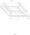
- FIG. 2 is a perspective view illustrating a state in which an external heating part 120 is disposed.
- the external heating part 120 may be disposed outside the transfer module 10 to heat the pouch P.
- the external heating part 120 may be disposed at the upper side of the pouch P to apply heat toward the pouch P.
- the external heating part 120 may be disposed on a moving path of the pouch P to apply heat toward the pouch P until the pouch P is folded.
- FIG. 3 is a perspective view illustrating a state in which the electrode assembly C is seated, and the external heating part 120 is disposed in the pouch P.
- the cup part U may be molded at one side with respect to a central folding line F of the pouch P, and then, the pouch P may be folded along the folding line F by the folding module 13, which will be described later, and the external heating part 120 may be disposed to be perpendicular to the folding line F. That is, a longitudinal direction of the external heating part 120 may be perpendicular to the folding line F. In other words, the external heating part 120 may have a bar shape and be disposed to be perpendicular to the folding line F.
- the external heating part 120 may be disposed in pair at both sides of the pouch P.
- the electrode assembly C may be constituted by an electrode E and a pair of lead tabs L bonded to both sides of the electrode E, and the external heating part 120 may be disposed to correspond to the pair of lead tabs L.
- the electrode assembly C may be seated in one cup part U of the pouch P before folding the pouch P so that a connection line connecting the pair of lead tabs L to each other is parallel to the folding line F.
- the pair of external heating parts 120 may be disposed to correspond to the pair of lead tabs L.
- the external heating parts 120 may be disposed in pair at the upper side and both the sides of the pouch P so as to be perpendicular to the folding line F, and the electrode assembly C may be seated in the cup part U in the state in which the pair of lead tabs L are disposed in a heating area 120a of the pouch P, which is heated by the pair of external heating parts 120.
- the heating area 120a may mean a portion of the terrace part T heated by the external heating part 120.
- the heating area 120a may be defined on an extension surface of the terrace part T of the external heating part 120, and specifically, the terrace part T may be disposed at each of both sides of the terrace part T in the longitudinal direction perpendicular to the folding line F.
- the external heating part 120 may be separated from the pouch P.
- the external heating part 120 may be separated from both the sides of the pouch P.
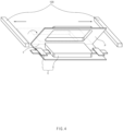
- the external heating part 120 may move horizontally in a direction parallel to the folding line F in the state in which the pair of external heating parts 120 are disposed at the upper side of the pouch P and then may be separated from the pouch P as viewed from the above.
- the external heating part 120 may be separated from the pouch P before the pouch P is folded. That is, after the external heating part 120 applies heat to the pouch P and is separated, the pouch P may be folded. Thus, the external heating part 120 may not be disposed on the folding path of the pouch P to previously prevent the external heating part 120 from interfering and colliding due to the folding operation of the pouch P.
- the internal heating part 121 may be provided in the transfer module 10 to heat the pouch P.
- the internal heating part 121 may be provided inside the transfer module 10 to apply heat to the transfer module 10, and thus, the heat generated in the internal heating part 121 may be transferred to the pouch P through the transfer module 10.
- the internal heating part 121 may move integrally with the transfer module 10 in a state of being built in the transfer module 10, and the internal heating part 121 may apply heat to the transferred pouch P.
- the internal heating part 121 may be connected to and disposed in the transfer module 10 in various forms such as a heating wire, a heat pipe, and a block.
- the internal heating part 121 may be disposed in the transfer module 10 along the terrace part T of the pouch P. Specifically, when viewed from the top, the internal heating part 121 may be disposed in the transfer module 10 to overlap the terrace part T of the pouch P. That is, like the external heating part 120, the internal heating part 121 may be disposed at both sides of the pouch P so as to be perpendicular to the folding line F when viewed from the above.
- the internal heating part 121 may be disposed to overlap the terrace part T of the pouch P in the vertical direction.
- the internal heating part 121 may face the external heating part 120 with the terrace part T of the pouch P therebetween.
- FIG. 5 is a perspective view illustrating a configuration of the pouch P folded by the folding module 13.
- the apparatus 1 for manufacturing the secondary battery may further include the folding module 13 that folds the pouch P.
- the folding module 13 may fold the pouch P along the folding line F so that the cup parts U disposed at both the sides of the folding line F are in contact with each other to define the accommodation space.
- the folding module 13 may include a body 130 and a cover part 131.
- the body 130 may apply external force to one of the cup parts U disposed at both the sides based on the folding line F of the pouch P so that the pouch P is folded around the folding line F.
- the body 130 may apply external force toward one cup part U after being in contact with an outer surface of one cup part U so that the two cup parts U are in contact with each other to define the accommodation space.
- the cover part 131 may be connected to both sides of the body 130 to cover the terrace part T of the pouch P.
- the pair of cover parts 131 may extend from both the sides of the body 130 to one side of the body 130 so as to be perpendicular to the folding line F. That is, the pair of cover parts 131 may cover the terrace part T to cover the heating area 120a.
- the heat may be transferred to the terrace part T through the cover part 131, and like the function of the heating module 12, the terrace part T may be preheated before the sealing process.
- the heating module 12 and the folding module 13 may be disposed in front of the sealing module 11 with respect to the transfer direction of the pouch P to previously transfer sufficient heat to the pouch P, and thus, the apparatus 1 for manufacturing the secondary battery may secure the sealing strength of the pouch P to improve the quality and yield of the secondary battery.
- FIG. 6 is a block diagram illustrating a method for manufacturing a secondary battery according to another embodiment.
- a secondary battery may be manufactured by sealing a pouch P accommodating an electrode assembly C therein through a method for manufacturing the secondary battery.
- the pouch P may be previously preheated to perform a more intensive sealing operation, and as a result, efficiency of the process of manufacturing the secondary battery and yield of the secondary battery may be improved.
- the method for manufacturing the secondary battery may include a heating process (S10), a separation process (S20), a folding process (S30), and a sealing process (S40).
- an external heating part 120 or an internal heating part 121 may heat the pouch P transferred by a transfer module 10.
- the external heating part 120 may be disposed outside the transfer module 10 to heat the pouch P.
- cup parts U may be molded at both sides based on a central folding line F of the pouch P, and the pouch P may be folded along the folding line F by the folding module 13.
- the external heating part 120 may be disposed to be perpendicular to the folding line F.
- the external heating part 120 may be disposed in pair at both the sides of the pouch P.
- an electrode assembly C may be constituted by an electrode E and a pair of lead tabs L bonded to both sides of the electrode E, and the external heating part 120 may be disposed to correspond to the pair of lead tabs L.
- the internal heating part 121 may be provided in the transfer module 10 to heat the pouch P.
- the internal heating part 121 may be disposed in the transfer module 10 along the terrace part T of the pouch P. Specifically, when viewed from the top, the internal heating part 121 may be disposed in the transfer module 10 to overlap the terrace part T of the pouch P.
- the internal heating part 121 may be disposed at both the sides of the pouch P so as to be perpendicular to the folding line F when viewed from the above.
- the external heating part 120 may be separated to both the sides of the pouch P when viewed from the top. Specifically, the external heating part 120 may move horizontally in a direction parallel to the folding line F in the state in which the pair of external heating parts 120 are disposed at the upper side of the pouch P and then may be separated from the pouch P as viewed from the above.
- the pouch P may be folded along the folding line F by the folding module 13.
- the folding module 13 may fold the pouch P along the folding line F so that the cup parts U disposed at both the sides of the folding line F are in contact with each other to define the accommodation space.
- the sealing module 11 may seal the terrace part T of the pouch P in a state in which the pouch P is folded so that the electrode assembly C is accommodated in the cup part U of the pouch P.
- the sealing module 11 may seal the pouch P by thermally fusing the terrace part T at a high-temperature and high-pressure.
Landscapes
- Engineering & Computer Science (AREA)
- Mechanical Engineering (AREA)
- Physics & Mathematics (AREA)
- Chemical Kinetics & Catalysis (AREA)
- General Chemical & Material Sciences (AREA)
- Electrochemistry (AREA)
- Chemical & Material Sciences (AREA)
- Electromagnetism (AREA)
- Health & Medical Sciences (AREA)
- Toxicology (AREA)
- Thermal Sciences (AREA)
- Manufacturing & Machinery (AREA)
- Sealing Battery Cases Or Jackets (AREA)
- Connection Of Batteries Or Terminals (AREA)
- Lining Or Joining Of Plastics Or The Like (AREA)
- Secondary Cells (AREA)
Abstract
Description
- The present application claims the benefit of the priority of
Korean Patent Application No. 10-2022-0081503, filed on July 1, 2022 - The present includes relates to an apparatus and method for manufacturing a secondary battery.
- In general, secondary batteries include nickelcadmium batteries, nickel-hydrogen batteries, lithium ion batteries, and lithium ion polymer batteries. Such a secondary battery is being applied to be used in small-sized products such as digital cameras, P-DVDs, MP3Ps, mobile phones, PDAs, portable game devices, power tools, E-bikes, and the like as well as large-sized products requiring high power such as electric vehicles and hybrid vehicles, power storage devices for storing surplus power or renewable energy, and backup power storage devices.
- In general, in order to manufacture the secondary battery, first, electrode active material slurry is applied to a positive electrode collector and a negative electrode collector to manufacture a positive electrode and a negative electrode. Then, the electrodes are stacked on both sides of a separator to form an electrode assembly. Also, the electrode assembly is accommodated in a battery case, and then the battery case is sealed after an electrolyte is injected therein.
- Such a secondary battery is classified into a pouch-type secondary battery and a can-type secondary battery according to a material of a case accommodating the electrode assembly. In the pouch-type secondary battery, an electrode assembly is accommodated in a pouch made of a flexible polymer material. Also, in the can-type secondary battery, an electrode assembly is accommodated in a case made of a metal or plastic material.
- In general, a pouch-type battery case is manufactured by performing press processing on a pouch film having flexibility to form a cup part. In addition, when the cup part is formed, an electrode assembly is accommodated in the cup part, and then, a side of the cup part is sealed to manufacture a secondary battery.
- Specifically, in a state in which the electrode assembly is accommodated in the cup part, the pouch may be folded along a folding line to cover the electrode assembly, and the sealing device may thermally fuse a side portion formed along a circumference of the cup part at a high-temperature and high-pressure.
- Since a sealing process is performed for a relatively short time, there are cases in which the sealing process is performed without reaching the high-temperature for the thermal fusion. If the sealing process is performed in a state in which sufficient heat is not transferred, sealing strength of the pouch is weakened, resulting in deteriorated yield and quality of secondary batteries. Therefore, for more smooth sealing process, there is a need for an apparatus for manufacturing a secondary battery provided with a device that transfers sufficient heat to the pouch.
- An object of the present invention for solving the above problem is to provide an apparatus for manufacturing a secondary battery, which secures sealing strength of a pouch by preheating the pouch.
- An apparatus for manufacturing a secondary battery according to an embodiment of the present invention may include a transfer module configured to transfer a pouch, a heating module comprising at least one of an internal heating part provided in the transfer module to heat the pouch and an external heating part disposed outside the transfer module to heat the pouch, and a sealing module disposed behind the heating module in a transfer direction of the pouch to seal a terrace part of the pouch in a state in which the pouch is folded so that an electrode assembly is accommodated in a cup part of the pouch.
- The pouch may be folded along a folding line, and a longitudinal direction of the external heating part may be perpendicular to the folding line.
- The external heating part may be provided in pair, which are disposed at both sides of the pouch.
- The electrode assembly may include an electrode and a pair of lead tabs bonded to both sides of the electrode, and when viewed from the above, the pair of external heating parts may be disposed to correspond to the pair of lead tabs.
- The external heating part may move horizontally.
- The external heating part may be disposed in pair at both sides of the pouch, and when viewed from the above, the pair of external heating parts may be separated from both the sides of the pouch.
- After the external heating part is separated from the pouch, the pouch may be folded.
- The internal heating part may be disposed in the transfer module along the terrace part.
- The pouch may be folded along a folding line, and a longitudinal direction of the internal heating part may be perpendicular to the folding line.
- A method for manufacturing a secondary battery according to another embodiment of the present invention may include a heating process of heating a pouch by at least one of an external heating part disposed outside a transfer module or an internal heating part provided in the transfer module in a process of transferring the pouch by the transfer module, and a sealing process of the terrace part of the pouch by a sealing module in a state in which the pouch is folded so that an electrode assembly is accommodated in a cup part of the pouch.
- The method may further include a folding process of folding the pouch along a folding line.
- In the heating process, the external heating part may be disposed to be perpendicular to the folding line and is provided in pair at both sides of the pouch.
- The method may further include, before the folding process, a separation process of separating the external heating part to both sides of the pouch when viewed from the above.
- In the heating process, the internal heating part may be disposed in the transfer module along the terrace part.
- According to the preferred embodiment of the present invention, the pouch may be preheated to secure the sealing strength of the pouch, thereby improving the quality and yield of the secondary battery.
- In addition, the effects that are obvious to those skilled in the art may be predicted from the configurations according to the embodiment of the present invention.
- The following drawings attached in this specification illustrate a preferred embodiment of the present invention and function to make further understood the technical spirit of the present invention along with the detailed description of the invention, and thus, the present invention should not be construed as being limited to only the drawings.
-
FIG. 1 is a perspective view illustrating an apparatus for manufacturing a secondary battery according to an embodiment. -
FIG. 2 is a perspective view illustrating a state in which an external heating part is disposed. -
FIG. 3 is a perspective view illustrating a state in which an electrode assembly is seated, and the external heating part is disposed in the pouch. -
FIG. 4 is a perspective view illustrating a state in which the external heating part is separated from the pouch. -
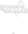
FIG. 5 is a perspective view illustrating a configuration of the pouch folded by a folding module. -
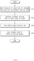
FIG. 6 is a block diagram illustrating a method for manufacturing a secondary battery according to another embodiment. - Hereinafter, preferred embodiments of the present invention will be described in detail with reference to the accompanying drawings so that those of ordinary skill in the art can easily carry out the present invention. However, the present invention may be implemented in several different forms and is not limited or restricted by the following examples.
- In order to clearly explain the present invention, detailed descriptions of portions that are irrelevant to the description or related known technologies that may unnecessarily obscure the gist of the present invention have been omitted, and in the present specification, reference symbols are added to components in each drawing. In this case, the same or similar reference numerals are assigned to the same or similar elements throughout the specification.
- Also, terms or words used in this specification and claims should not be restrictively interpreted as ordinary meanings or dictionary-based meanings, but should be interpreted as meanings and concepts conforming to the scope of the present invention on the basis of the principle that an inventor can properly define the concept of a term to describe and explain his or her invention in the best ways.
-
FIG. 1 is a perspective view illustrating anapparatus 1 for manufacturing a secondary battery according to an embodiment. - Referring to
FIG. 1 , the apparatus for manufacturing the secondary battery may manufacture a secondary battery by accommodating an electrode assembly C into a pouch P to seal the pouch P. For example, theapparatus 1 for manufacturing the secondary battery may mold a cup part U in the pouch P to define an accommodation space and then dispose the electrode assembly C in the cup part U of the pouch P and thermally fuse a side portion of the pouch P at high-temperature and high-pressure to seal the pouch P. - In addition, the
apparatus 1 for manufacturing the secondary battery may preheat the pouch P in a process of transferring the pouch P, in which the cup part U is molded, before sealing the pouch P. Specifically, theapparatus 1 for manufacturing the secondary battery may preheat the pouch P when the pouch P in which the cup part U is molded is transported alone and also may preheat the pouch P in a process of seating the electrode assembly C in the cup part U to transfer the pouch P and the electrode assembly C. - As described above, the
apparatus 1 for manufacturing the secondary battery may preheat the pouch P before sealing the pouch P, and thus, theapparatus 1 for manufacturing the secondary battery may more secure sealing strength of the pouch P to improve efficiency in manufacturing process and also improve yield and quality of the secondary battery. - The
apparatus 1 for manufacturing the secondary battery may include atransfer module 10, asealing module 11, and aheating module 12. - The
transfer module 10 may transfer the pouch P. For example, thetransfer module 10 may adsorb and fix the pouch P in a vacuum adsorption manner and then transfer the pouch P. When thetransfer module 10 transfers the pouch P in which the cup part U is molded, the electrode assembly C may be seated in the cup part U of the pouch P, and thetransfer module 10 may transfer the pouch P and the electrode assembly C again in the state in which the electrode assembly C is seated in the cup part U of the pouch P. Thereafter, thetransfer module 10 may transfer the pouch P, in which the electrode assembly C is accommodated, to afolding module 13, which will be described later, and then, the folded pouch P may be transferred to thesealing module 11, which will be described later. - The
sealing module 11 may seal the pouch P in the state in which the electrode assembly C is accommodated in the pouch P. For example, the pouch P may be constituted by the recessed cup part U and a terrace part T disposed along a circumference of the cup part U, and the electrode assembly C may be accommodated in the pouch P by folding the pouch P in the state in which the electrode assembly C is seated in the cup part U of the pouch P. Thereafter, thesealing module 11 may seal the pouch P by thermally fusing the terrace part T at a high-temperature and high-pressure. - Specifically, the
sealing module 11 may include a sealing block provided at each of upper and lower sides of the folded pouch P and may apply a pressure to each of top and bottom surfaces of the folded pouch P, which is folded by the sealing block, to thermally fuse the pouch P. - The
heating module 12 may heat the transported pouch P. For example, theheating module 12 may be provided in thetransfer module 10 to apply heat to the pouch P seated in thetransfer module 10. In addition, theheating module 12 may be disposed outside thetransfer module 10 to apply heat to an outer surface of the pouch P being transferred by thetransfer module 10. Specifically, theheating module 12 may include at least one of anexternal heating part 120 or aninternal heating part 121. -
FIG. 2 is a perspective view illustrating a state in which anexternal heating part 120 is disposed. - Referring to
FIG. 2 , theexternal heating part 120 may be disposed outside thetransfer module 10 to heat the pouch P. For example, theexternal heating part 120 may be disposed at the upper side of the pouch P to apply heat toward the pouch P. Specifically, theexternal heating part 120 may be disposed on a moving path of the pouch P to apply heat toward the pouch P until the pouch P is folded. -
FIG. 3 is a perspective view illustrating a state in which the electrode assembly C is seated, and theexternal heating part 120 is disposed in the pouch P. - Referring to
FIG. 3 , the cup part U may be molded at one side with respect to a central folding line F of the pouch P, and then, the pouch P may be folded along the folding line F by thefolding module 13, which will be described later, and theexternal heating part 120 may be disposed to be perpendicular to the folding line F. That is, a longitudinal direction of theexternal heating part 120 may be perpendicular to the folding line F. In other words, theexternal heating part 120 may have a bar shape and be disposed to be perpendicular to the folding line F. - In addition, the
external heating part 120 may be disposed in pair at both sides of the pouch P. For example, the electrode assembly C may be constituted by an electrode E and a pair of lead tabs L bonded to both sides of the electrode E, and theexternal heating part 120 may be disposed to correspond to the pair of lead tabs L. Specifically, the electrode assembly C may be seated in one cup part U of the pouch P before folding the pouch P so that a connection line connecting the pair of lead tabs L to each other is parallel to the folding line F. In this case, when viewed from the above, the pair ofexternal heating parts 120 may be disposed to correspond to the pair of lead tabs L. - In other words, the
external heating parts 120 may be disposed in pair at the upper side and both the sides of the pouch P so as to be perpendicular to the folding line F, and the electrode assembly C may be seated in the cup part U in the state in which the pair of lead tabs L are disposed in aheating area 120a of the pouch P, which is heated by the pair ofexternal heating parts 120. Here, theheating area 120a may mean a portion of the terrace part T heated by theexternal heating part 120. In other words, theheating area 120a may be defined on an extension surface of the terrace part T of theexternal heating part 120, and specifically, the terrace part T may be disposed at each of both sides of the terrace part T in the longitudinal direction perpendicular to the folding line F. -
FIG. 4 is a perspective view illustrating a state in which theexternal heating part 120 is separated from the pouch P. - Referring to
FIG. 4 , theexternal heating part 120 may be separated from the pouch P. For example, theexternal heating part 120 may be separated from both the sides of the pouch P. Specifically, theexternal heating part 120 may move horizontally in a direction parallel to the folding line F in the state in which the pair ofexternal heating parts 120 are disposed at the upper side of the pouch P and then may be separated from the pouch P as viewed from the above. - More specifically, the
external heating part 120 may be separated from the pouch P before the pouch P is folded. That is, after theexternal heating part 120 applies heat to the pouch P and is separated, the pouch P may be folded. Thus, theexternal heating part 120 may not be disposed on the folding path of the pouch P to previously prevent theexternal heating part 120 from interfering and colliding due to the folding operation of the pouch P. - The
internal heating part 121 may be provided in thetransfer module 10 to heat the pouch P. For example, theinternal heating part 121 may be provided inside thetransfer module 10 to apply heat to thetransfer module 10, and thus, the heat generated in theinternal heating part 121 may be transferred to the pouch P through thetransfer module 10. However, this is only an example of theinternal heating part 121, and theinternal heating part 121 may be connected to thetransfer module 10 in various forms, such as being attached to the outer surface of thetransfer module 10. - The
internal heating part 121 may move integrally with thetransfer module 10 in a state of being built in thetransfer module 10, and theinternal heating part 121 may apply heat to the transferred pouch P. Theinternal heating part 121 may be connected to and disposed in thetransfer module 10 in various forms such as a heating wire, a heat pipe, and a block. - The
internal heating part 121 may be disposed in thetransfer module 10 along the terrace part T of the pouch P. Specifically, when viewed from the top, theinternal heating part 121 may be disposed in thetransfer module 10 to overlap the terrace part T of the pouch P. That is, like theexternal heating part 120, theinternal heating part 121 may be disposed at both sides of the pouch P so as to be perpendicular to the folding line F when viewed from the above. - The
internal heating part 121 may be disposed to overlap the terrace part T of the pouch P in the vertical direction. Theinternal heating part 121 may face theexternal heating part 120 with the terrace part T of the pouch P therebetween. -
FIG. 5 is a perspective view illustrating a configuration of the pouch P folded by thefolding module 13. - Referring to
FIG. 5 , theapparatus 1 for manufacturing the secondary battery may further include thefolding module 13 that folds the pouch P. Thefolding module 13 may fold the pouch P along the folding line F so that the cup parts U disposed at both the sides of the folding line F are in contact with each other to define the accommodation space. Specifically, thefolding module 13 may include abody 130 and acover part 131. - The
body 130 may apply external force to one of the cup parts U disposed at both the sides based on the folding line F of the pouch P so that the pouch P is folded around the folding line F. In other words, thebody 130 may apply external force toward one cup part U after being in contact with an outer surface of one cup part U so that the two cup parts U are in contact with each other to define the accommodation space. - The
cover part 131 may be connected to both sides of thebody 130 to cover the terrace part T of the pouch P. For example, in a state in which a longitudinal direction of thebody 130 is disposed parallel to the folding line F, the pair ofcover parts 131 may extend from both the sides of thebody 130 to one side of thebody 130 so as to be perpendicular to the folding line F. That is, the pair ofcover parts 131 may cover the terrace part T to cover theheating area 120a. - The heat may be transferred to the terrace part T through the
cover part 131, and like the function of theheating module 12, the terrace part T may be preheated before the sealing process. - As a result, since the sealing process of the sealing
module 11 is performed for a relatively short time and also be performed without sufficient heat being applied to the pouch P, theheating module 12 and thefolding module 13 may be disposed in front of the sealingmodule 11 with respect to the transfer direction of the pouch P to previously transfer sufficient heat to the pouch P, and thus, theapparatus 1 for manufacturing the secondary battery may secure the sealing strength of the pouch P to improve the quality and yield of the secondary battery. - Hereinafter, a method for manufacturing a secondary battery according to another embodiment is disclosed. Contents duplicated with the configuration and function of the
apparatus 1 for manufacturing the secondary battery described above will be omitted below. -
FIG. 6 is a block diagram illustrating a method for manufacturing a secondary battery according to another embodiment. - Referring to
FIG. 6 , a secondary battery may be manufactured by sealing a pouch P accommodating an electrode assembly C therein through a method for manufacturing the secondary battery. In a process of manufacturing the secondary battery, before sealing the pouch P, the pouch P may be previously preheated to perform a more intensive sealing operation, and as a result, efficiency of the process of manufacturing the secondary battery and yield of the secondary battery may be improved. - The method for manufacturing the secondary battery may include a heating process (S10), a separation process (S20), a folding process (S30), and a sealing process (S40).
- In the heating process (S10), at least one of an
external heating part 120 or aninternal heating part 121 may heat the pouch P transferred by atransfer module 10. Specifically, theexternal heating part 120 may be disposed outside thetransfer module 10 to heat the pouch P. More specifically, cup parts U may be molded at both sides based on a central folding line F of the pouch P, and the pouch P may be folded along the folding line F by thefolding module 13. Thus, theexternal heating part 120 may be disposed to be perpendicular to the folding line F. - In addition, the
external heating part 120 may be disposed in pair at both the sides of the pouch P. For example, an electrode assembly C may be constituted by an electrode E and a pair of lead tabs L bonded to both sides of the electrode E, and theexternal heating part 120 may be disposed to correspond to the pair of lead tabs L. - The
internal heating part 121 may be provided in thetransfer module 10 to heat the pouch P. Theinternal heating part 121 may be disposed in thetransfer module 10 along the terrace part T of the pouch P. Specifically, when viewed from the top, theinternal heating part 121 may be disposed in thetransfer module 10 to overlap the terrace part T of the pouch P. Theinternal heating part 121 may be disposed at both the sides of the pouch P so as to be perpendicular to the folding line F when viewed from the above. - In the separation process (S20), the
external heating part 120 may be separated to both the sides of the pouch P when viewed from the top. Specifically, theexternal heating part 120 may move horizontally in a direction parallel to the folding line F in the state in which the pair ofexternal heating parts 120 are disposed at the upper side of the pouch P and then may be separated from the pouch P as viewed from the above. - In the folding process (S30), the pouch P may be folded along the folding line F by the
folding module 13. Thefolding module 13 may fold the pouch P along the folding line F so that the cup parts U disposed at both the sides of the folding line F are in contact with each other to define the accommodation space. - In the sealing process (S40), the sealing
module 11 may seal the terrace part T of the pouch P in a state in which the pouch P is folded so that the electrode assembly C is accommodated in the cup part U of the pouch P. In other words, the sealingmodule 11 may seal the pouch P by thermally fusing the terrace part T at a high-temperature and high-pressure. - The above-disclosed subject matter is to be considered illustrative, and not restrictive, and the appended claims are intended to cover all such modifications, enhancements, and other embodiments, which fall within the true spirit and scope of the present invention.
- Thus, the embodiment of the present invention is to be considered illustrative, and not restrictive, and the technical spirit of the present invention is not limited to the foregoing embodiment.
- Therefore, the scope of the present invention is defined not by the detailed description of the invention but by the appended claims, and all differences within the scope will be construed as being included in the present invention.
-
- 1: Apparatus for manufacturing secondary battery
- 10: Transfer module
- 11: Sealing module
- 12: Heating module
- 13: Folding module
- 120: External heating part
- 121: Internal heating part
- 120a: Heating area
- 130: Body
- 131: Cover part
- S10: Heating process
- S20: Separation process
- S30: Folding process
- S40: Sealing process
- P: Pouch
- U: Cup part
- F: Folding line
- F: Folding line
- C: Electrode assembly
- E: Electrode
- L: Lead tab
Claims (14)
- An apparatus for manufacturing a secondary battery, the apparatus comprising:a transfer module configured to transfer a pouch;a heating module comprising at least one of an internal heating part provided in the transfer module to heat the pouch and an external heating part disposed outside the transfer module to heat the pouch; anda sealing module disposed behind the heating module in a transfer direction of the pouch to seal a terrace part of the pouch in a state in which the pouch is folded so that an electrode assembly is accommodated in a cup part of the pouch.
- The apparatus of claim 1, wherein the pouch is folded along a folding line, and
a longitudinal direction of the external heating part is perpendicular to the folding line. - The apparatus of claim 2, wherein the external heating part is provided in pair, which are disposed at both sides of the pouch.
- The apparatus of claim 3, wherein the electrode assembly comprises an electrode and a pair of lead tabs bonded to both sides of the electrode, and
when viewed from the above, the pair of external heating parts are disposed to correspond to the pair of lead tabs. - The apparatus of claim 1, wherein the external heating part moves horizontally.
- The apparatus of claim 5, wherein the external heating part is disposed in pair at both sides of the pouch, and
when viewed from the above, the pair of external heating parts are separated from both the sides of the pouch. - The apparatus of claim 6, wherein, after the external heating part is separated from the pouch, the pouch is folded.
- The apparatus of claim 1, wherein the internal heating part is disposed in the transfer module along the terrace part.
- The apparatus of claim 8, wherein the pouch is folded along a folding line, and
a longitudinal direction of the internal heating part is perpendicular to the folding line. - A method for manufacturing a secondary battery, the method comprising:a heating process of heating a pouch by at least one of an external heating part disposed outside a transfer module or an internal heating part provided in the transfer module in a process of transferring the pouch by the transfer module; anda sealing process of the terrace part of the pouch by a sealing module in a state in which the pouch is folded so that an electrode assembly is accommodated in a cup part of the pouch.
- The method of claim 10, further comprising a folding process of folding the pouch along a folding line.
- The method of claim 11, wherein, in the heating process, the external heating part is disposed to be perpendicular to the folding line and is provided in pair at both sides of the pouch.
- The method of claim 11, further comprising, before the folding process, a separation process of separating the external heating part to both sides of the pouch when viewed from the above.
- The method of claim 10, wherein, in the heating process, the internal heating part is disposed in the transfer module along the terrace part.
Applications Claiming Priority (2)
| Application Number | Priority Date | Filing Date | Title |
|---|---|---|---|
| KR1020220081503A KR20240003663A (en) | 2022-07-01 | 2022-07-01 | Apparatus of manufacturing a secondary battery and method of manufacturing the secondary battery |
| PCT/KR2023/009183 WO2024005583A1 (en) | 2022-07-01 | 2023-06-29 | Secondary battery manufacturing apparatus and manufacturing method |
Publications (2)
| Publication Number | Publication Date |
|---|---|
| EP4530046A1 true EP4530046A1 (en) | 2025-04-02 |
| EP4530046A4 EP4530046A4 (en) | 2025-11-05 |
Family
ID=89381139
Family Applications (1)
| Application Number | Title | Priority Date | Filing Date |
|---|---|---|---|
| EP23831941.2A Pending EP4530046A4 (en) | 2022-07-01 | 2023-06-29 | DEVICE AND METHOD FOR MANUFACTURING A SECONDARY BATTERY |
Country Status (5)
| Country | Link |
|---|---|
| EP (1) | EP4530046A4 (en) |
| JP (1) | JP7815600B2 (en) |
| KR (1) | KR20240003663A (en) |
| CN (1) | CN119546449A (en) |
| WO (1) | WO2024005583A1 (en) |
Family Cites Families (14)
| Publication number | Priority date | Publication date | Assignee | Title |
|---|---|---|---|---|
| JP3661137B2 (en) * | 1998-02-19 | 2005-06-15 | タキロン株式会社 | Plastic hollow body manufacturing equipment |
| KR100400793B1 (en) * | 2001-01-18 | 2003-10-08 | 한국냉각캔주식회사 | Method of making high pressure vessels for a self-cooling beverage container |
| JP2009272161A (en) * | 2008-05-08 | 2009-11-19 | Toyota Motor Corp | Laminated battery, battery pack, and vehicle |
| KR20120126932A (en) * | 2011-05-13 | 2012-11-21 | 에스케이이노베이션 주식회사 | Sealing method and device of pouch type secondary battery |
| KR20140137694A (en) * | 2013-05-23 | 2014-12-03 | 넬슨(주) | Battery Read film sealing Device |
| WO2015012195A1 (en) * | 2013-07-22 | 2015-01-29 | 株式会社村田製作所 | Method for fabrication of laminated electrical storage device |
| JP6733190B2 (en) * | 2016-01-28 | 2020-07-29 | 株式会社村田製作所 | Separator welding apparatus and method for manufacturing laminated battery |
| KR102268400B1 (en) * | 2017-04-24 | 2021-06-24 | 주식회사 엘지에너지솔루션 | Secondary battery and sealing device for the same and sealing methode for the same |
| KR102700154B1 (en) * | 2018-04-26 | 2024-08-27 | 삼성에스디아이 주식회사 | Rechargeable battery, manufacturing apparatus and manufacturing metho of the same |
| KR102104319B1 (en) * | 2020-01-23 | 2020-04-24 | 주식회사 와이에이치티 | Heater press apparature included in folding system for heat pressurizing to terrace of secondary battery cell |
| KR102822974B1 (en) * | 2020-06-02 | 2025-06-20 | 주식회사 엘지에너지솔루션 | Manufacturing method for secondary battery |
| KR102955823B1 (en) * | 2020-12-01 | 2026-04-21 | 주식회사 엘지에너지솔루션 | Pouch-type secondary battery sealing device comprising a position adjustment part and sealing method of pouch-type secondary battery using the same |
| KR20220081503A (en) * | 2020-12-09 | 2022-06-16 | 주식회사 이지테크핀 | Liquid crystal display including conversion of digital signals |
| CN113594531B (en) * | 2021-07-29 | 2024-07-16 | 广东兆能科技有限公司 | Automatic side sealing device for soft package battery |
-
2022
- 2022-07-01 KR KR1020220081503A patent/KR20240003663A/en active Pending
-
2023
- 2023-06-29 CN CN202380048493.3A patent/CN119546449A/en active Pending
- 2023-06-29 WO PCT/KR2023/009183 patent/WO2024005583A1/en not_active Ceased
- 2023-06-29 EP EP23831941.2A patent/EP4530046A4/en active Pending
- 2023-06-29 JP JP2024575641A patent/JP7815600B2/en active Active
Also Published As
| Publication number | Publication date |
|---|---|
| CN119546449A (en) | 2025-02-28 |
| EP4530046A4 (en) | 2025-11-05 |
| JP2025520732A (en) | 2025-07-03 |
| KR20240003663A (en) | 2024-01-09 |
| JP7815600B2 (en) | 2026-02-18 |
| WO2024005583A1 (en) | 2024-01-04 |
Similar Documents
| Publication | Publication Date | Title |
|---|---|---|
| JP7038961B2 (en) | How to seal the side part of the pouch type battery including the two-step sealing process | |
| KR102347901B1 (en) | Pouch-Type Battery Case Having Structure to Prevent Crack and Method for Preparing the Same | |
| US10084161B2 (en) | Battery and method of producing the same | |
| JP7047220B2 (en) | Battery module including rechargeable battery and bus bar | |
| US20230264430A1 (en) | Sealing Apparatus for Secondary Battery | |
| CN119631229A (en) | Soft-pack type battery cell and method for manufacturing the soft-pack type battery cell | |
| KR20150137454A (en) | Method for manufacturing second battery using hybrid high frequency sealing | |
| KR20220003729A (en) | Battery module and battery pack including the same and manufacturing method of the same | |
| EP4027437A1 (en) | Battery cell and method of manufacturing the same | |
| JP7815600B2 (en) | Secondary battery manufacturing apparatus and manufacturing method | |
| US12586809B2 (en) | Method for manufacturing secondary battery, coupling clip for manufacturing secondary battery, and secondary battery | |
| US20230369690A1 (en) | Secondary Battery And Method For Manufacturing The Same | |
| CN119343818A (en) | Battery Module | |
| KR101755073B1 (en) | Secondary battery and method for manufacture the same | |
| EP4579830A1 (en) | Method for manufacturing secondary battery | |
| US20250300279A1 (en) | Pouch-Type Battery Case and Pouch-Type Secondary Battery Including the Same, Method for Pouch-Type Battery Case, and Forming Jig for Manufacturing Pouch-Type Battery Case | |
| US20240332687A1 (en) | Battery cell, manufacturing device for battery cell and manufacturing method of battery cell | |
| US20260100439A1 (en) | Secondary battery | |
| EP4517945A1 (en) | Pouch-type battery case, pouch-type secondary battery comprising same, method for manufacturing pouch-type battery case, and molding jig for manufacturing pouch-type battery case | |
| KR102920616B1 (en) | Battery cell and manufacturing device for the same | |
| US20250219211A1 (en) | Secondary battery including cap plate with improved sealing ability | |
| EP4550491A1 (en) | Folding device and folding method | |
| US20250174703A1 (en) | Apparatus and Method for Sealing Electrode Assembly | |
| KR20260035442A (en) | Secondary battert | |
| KR20250146795A (en) | Electrode assembly, protective tape attachment apparatus and method |
Legal Events
| Date | Code | Title | Description |
|---|---|---|---|
| STAA | Information on the status of an ep patent application or granted ep patent |
Free format text: STATUS: THE INTERNATIONAL PUBLICATION HAS BEEN MADE |
|
| PUAI | Public reference made under article 153(3) epc to a published international application that has entered the european phase |
Free format text: ORIGINAL CODE: 0009012 |
|
| STAA | Information on the status of an ep patent application or granted ep patent |
Free format text: STATUS: REQUEST FOR EXAMINATION WAS MADE |
|
| 17P | Request for examination filed |
Effective date: 20241225 |
|
| AK | Designated contracting states |
Kind code of ref document: A1 Designated state(s): AL AT BE BG CH CY CZ DE DK EE ES FI FR GB GR HR HU IE IS IT LI LT LU LV MC ME MK MT NL NO PL PT RO RS SE SI SK SM TR |
|
| DAV | Request for validation of the european patent (deleted) | ||
| DAX | Request for extension of the european patent (deleted) | ||
| A4 | Supplementary search report drawn up and despatched |
Effective date: 20251008 |
|
| RIC1 | Information provided on ipc code assigned before grant |
Ipc: B29C 65/00 20060101AFI20251001BHEP Ipc: H01M 50/105 20210101ALI20251001BHEP Ipc: B29L 31/00 20060101ALI20251001BHEP Ipc: B29C 53/84 20060101ALI20251001BHEP Ipc: B29C 53/36 20060101ALI20251001BHEP |