EP4529971A1 - Filter mit umlaufendem dichtelement - Google Patents
Filter mit umlaufendem dichtelement Download PDFInfo
- Publication number
- EP4529971A1 EP4529971A1 EP23199850.1A EP23199850A EP4529971A1 EP 4529971 A1 EP4529971 A1 EP 4529971A1 EP 23199850 A EP23199850 A EP 23199850A EP 4529971 A1 EP4529971 A1 EP 4529971A1
- Authority
- EP
- European Patent Office
- Prior art keywords
- filter
- sealing
- filter element
- circumferential
- sealing element
- Prior art date
- Legal status (The legal status is an assumption and is not a legal conclusion. Google has not performed a legal analysis and makes no representation as to the accuracy of the status listed.)
- Pending
Links
Images


Classifications
-
- B—PERFORMING OPERATIONS; TRANSPORTING
- B01—PHYSICAL OR CHEMICAL PROCESSES OR APPARATUS IN GENERAL
- B01D—SEPARATION
- B01D46/00—Filters or filtering processes specially modified for separating dispersed particles from gases or vapours
- B01D46/10—Particle separators, e.g. dust precipitators, using filter plates, sheets or pads having plane surfaces
- B01D46/12—Particle separators, e.g. dust precipitators, using filter plates, sheets or pads having plane surfaces in multiple arrangements
-
- B—PERFORMING OPERATIONS; TRANSPORTING
- B01—PHYSICAL OR CHEMICAL PROCESSES OR APPARATUS IN GENERAL
- B01D—SEPARATION
- B01D46/00—Filters or filtering processes specially modified for separating dispersed particles from gases or vapours
- B01D46/0002—Casings; Housings; Frame constructions
- B01D46/0004—Details of removable closures, lids, caps or filter heads
-
- B—PERFORMING OPERATIONS; TRANSPORTING
- B01—PHYSICAL OR CHEMICAL PROCESSES OR APPARATUS IN GENERAL
- B01D—SEPARATION
- B01D46/00—Filters or filtering processes specially modified for separating dispersed particles from gases or vapours
- B01D46/0002—Casings; Housings; Frame constructions
- B01D46/0005—Mounting of filtering elements within casings, housings or frames
-
- B—PERFORMING OPERATIONS; TRANSPORTING
- B01—PHYSICAL OR CHEMICAL PROCESSES OR APPARATUS IN GENERAL
- B01D—SEPARATION
- B01D46/00—Filters or filtering processes specially modified for separating dispersed particles from gases or vapours
- B01D46/0027—Filters or filtering processes specially modified for separating dispersed particles from gases or vapours with additional separating or treating functions
- B01D46/0036—Filters or filtering processes specially modified for separating dispersed particles from gases or vapours with additional separating or treating functions by adsorption or absorption
-
- B—PERFORMING OPERATIONS; TRANSPORTING
- B01—PHYSICAL OR CHEMICAL PROCESSES OR APPARATUS IN GENERAL
- B01D—SEPARATION
- B01D46/00—Filters or filtering processes specially modified for separating dispersed particles from gases or vapours
- B01D46/52—Particle separators, e.g. dust precipitators, using filters embodying folded corrugated or wound sheet material
- B01D46/521—Particle separators, e.g. dust precipitators, using filters embodying folded corrugated or wound sheet material using folded, pleated material
-
- B—PERFORMING OPERATIONS; TRANSPORTING
- B01—PHYSICAL OR CHEMICAL PROCESSES OR APPARATUS IN GENERAL
- B01D—SEPARATION
- B01D46/00—Filters or filtering processes specially modified for separating dispersed particles from gases or vapours
- B01D46/56—Filters or filtering processes specially modified for separating dispersed particles from gases or vapours with multiple filtering elements, characterised by their mutual disposition
- B01D46/62—Filters or filtering processes specially modified for separating dispersed particles from gases or vapours with multiple filtering elements, characterised by their mutual disposition connected in series
-
- B—PERFORMING OPERATIONS; TRANSPORTING
- B01—PHYSICAL OR CHEMICAL PROCESSES OR APPARATUS IN GENERAL
- B01D—SEPARATION
- B01D46/00—Filters or filtering processes specially modified for separating dispersed particles from gases or vapours
- B01D46/56—Filters or filtering processes specially modified for separating dispersed particles from gases or vapours with multiple filtering elements, characterised by their mutual disposition
- B01D46/62—Filters or filtering processes specially modified for separating dispersed particles from gases or vapours with multiple filtering elements, characterised by their mutual disposition connected in series
- B01D46/64—Filters or filtering processes specially modified for separating dispersed particles from gases or vapours with multiple filtering elements, characterised by their mutual disposition connected in series arranged concentrically or coaxially
-
- B—PERFORMING OPERATIONS; TRANSPORTING
- B60—VEHICLES IN GENERAL
- B60H—ARRANGEMENTS OF HEATING, COOLING, VENTILATING OR OTHER AIR-TREATING DEVICES SPECIALLY ADAPTED FOR PASSENGER OR GOODS SPACES OF VEHICLES
- B60H3/00—Other air-treating devices
- B60H3/06—Filtering
- B60H3/0658—Filter elements specially adapted for their arrangement in vehicles
-
- H—ELECTRICITY
- H01—ELECTRIC ELEMENTS
- H01M—PROCESSES OR MEANS, e.g. BATTERIES, FOR THE DIRECT CONVERSION OF CHEMICAL ENERGY INTO ELECTRICAL ENERGY
- H01M8/00—Fuel cells; Manufacture thereof
- H01M8/06—Combination of fuel cells with means for production of reactants or for treatment of residues
- H01M8/0662—Treatment of gaseous reactants or gaseous residues, e.g. cleaning
- H01M8/0687—Reactant purification by the use of membranes or filters
-
- B—PERFORMING OPERATIONS; TRANSPORTING
- B01—PHYSICAL OR CHEMICAL PROCESSES OR APPARATUS IN GENERAL
- B01D—SEPARATION
- B01D2271/00—Sealings for filters specially adapted for separating dispersed particles from gases or vapours
- B01D2271/02—Gaskets, sealings
-
- B—PERFORMING OPERATIONS; TRANSPORTING
- B01—PHYSICAL OR CHEMICAL PROCESSES OR APPARATUS IN GENERAL
- B01D—SEPARATION
- B01D2271/00—Sealings for filters specially adapted for separating dispersed particles from gases or vapours
- B01D2271/02—Gaskets, sealings
- B01D2271/027—Radial sealings
-
- B—PERFORMING OPERATIONS; TRANSPORTING
- B01—PHYSICAL OR CHEMICAL PROCESSES OR APPARATUS IN GENERAL
- B01D—SEPARATION
- B01D2279/00—Filters adapted for separating dispersed particles from gases or vapours specially modified for specific uses
- B01D2279/40—Filters adapted for separating dispersed particles from gases or vapours specially modified for specific uses for cleaning of environmental air, e.g. by filters installed on vehicles or on streets
-
- B—PERFORMING OPERATIONS; TRANSPORTING
- B01—PHYSICAL OR CHEMICAL PROCESSES OR APPARATUS IN GENERAL
- B01D—SEPARATION
- B01D2279/00—Filters adapted for separating dispersed particles from gases or vapours specially modified for specific uses
- B01D2279/60—Filters adapted for separating dispersed particles from gases or vapours specially modified for specific uses for the intake of internal combustion engines or turbines
-
- B—PERFORMING OPERATIONS; TRANSPORTING
- B60—VEHICLES IN GENERAL
- B60H—ARRANGEMENTS OF HEATING, COOLING, VENTILATING OR OTHER AIR-TREATING DEVICES SPECIALLY ADAPTED FOR PASSENGER OR GOODS SPACES OF VEHICLES
- B60H3/00—Other air-treating devices
- B60H3/06—Filtering
- B60H2003/0691—Adsorption filters, e.g. activated carbon
Definitions
- the invention relates to a filter for cleaning an air flow with at least a first filter element for a first filter stage and a second filter element for a second filter stage, wherein the second filter element is provided with a circumferential sealing element and the sealing element is integrally connected to the second filter element.
- Filter elements such as pocket filters, cassette filters, panel filters, edge band filters or flat filters are known from the state of the art. They are used for the filtration of fluids, especially air.
- the filter elements are usually inserted into filter housings and secured by means of fastening elements, e.g. screwed or latched.
- fastening elements e.g. screwed or latched.
- the connection between filter and filter frame must be highly leak-tight. To ensure this, additional seals are usually used.
- Such a filter is in the EP 3 453 441 B1 described.
- the interior air filter element comprises an adsorption filter layer with activated carbon, a fine filter layer, particularly for separating aerosols, and a circumferential seal for separating the raw gas side from the clean gas side when installed in a filter housing.
- each filter element must be securely sealed to the receiving filter housing. Care must also be taken during assembly to ensure that the filter element seals are not damaged.
- the object of the present invention is to provide a filter which has at least two filter elements for at least two filter stages, has a material-saving production and enables simple and safe installation in a filter holder.
- the filter is used to clean an air flow with at least a first filter element for a first filter stage and a second filter element for a Second filter stage.
- the second filter element is equipped with a circumferential sealing element, which is integrally bonded to the second filter element.
- the integral connection of the circumferential seal can be achieved, for example, by bonding or integrated manufacturing, thus ensuring a secure seal between the filter element and the filter holder.
- the sealing element has at least one external, circumferential sealing surface for sealing against a filter receptacle.
- the shape of the sealing surface corresponds to the shape of the filter receptacle.
- the filter receptacle can be a filter housing or an air duct.
- the external, circumferential sealing surface serves to radially seal the filter against the filter receptacle. Radial means radial to the extension and flow direction of the filter.
- the sealing element has an opening in the center through which the fluid to be filtered flows during filtration and which has an internal, circumferential sealing surface for sealing against the first filter element.
- the sealing element is thus shaped in such a way that it encloses both the first filter element and the second filter element in a frame-like manner. With just one sealing element, the first filter element is sealed against the second filter element and the second filter element is sealed against the filter housing.
- the first filter element is received in a press fit in the sealing element and the inner sealing surface rests against the first filter element with a press fit.
- the inner sealing surface of the sealing element is formed by a sealing lip.
- the sealing lip In its undeformed state, i.e., before the first filter element is inserted into the seal, the sealing lip can have an overlap of at least 1 millimeter with the mating surface of the first filter element.
- the sealing element and the first filter element are connected to each other by a force fit.
- the fit between the sealing element and the first filter element is selected to ensure a press fit or interference fit.
- a press fit can also be referred to as an interference fit. The press fit ensures that the first filter element is securely held in its installed position, even under mechanical stress during operation.
- the sealing element has been determined that it is advantageous to provide the sealing element with a circumferential compensation groove, which is designed as a circumferential recess arranged on the upstream side.
- the compensation groove can advantageously reduce restoring forces.
- the combination of sealing lip and compensation groove contributes to leak-free installation of the filter with very high tightness.
- the sealing element can be injection-molded onto the second filter element, i.e. formed as an injection-molded part made of injection-moldable material, in particular polyurethane or silicone.
- Shore A hardness greater than 20 of the sealing element material allows for good sealing.
- the Shore A hardness can be in the range of 20 to 50, particularly when measured according to DIN ISO 7619-1 or ISO 868 or ASTM D2240.
- the first filter element and, if applicable, also the second filter element are designed as bellows made of a pleated filter medium provided with peripheral edge bands. If the filter element has a rectangular shape when viewed from above, it is provided with edge bands on all four sides.
- the first filter element is designed to have a certain degree of inherent rigidity, so that the surrounding edge bands fit snugly against the inner sealing surface and are not deformed by the sealing surface.
- the edges of the two end pleats of the filter medium of the first filter element are oriented toward the upstream side of the filter.
- the first filter element is designed as a particle filter element and/or the second filter element is designed as an adsorption filter element.
- the adsorption filter element can contain, for example, activated carbon as the adsorbent.
- the invention also relates to a filter arrangement comprising a filter as described above and a filter housing for receiving the filter.
- the filter assembly has a frame-shaped cover that can be connected to the filter housing, or alternatively, a housing upper part as part of the filter housing, both of which serve to secure the filter in the filter housing. This also prevents the first filter element from slipping out of the sealing element.
- the invention also relates to the use of a filter arrangement as described above as an interior air filter arrangement for filtration and Cleaning the cabin air supply in a vehicle or as an air supply filter in a fuel cell unit.
- the cabin air filter assembly filters and cleans the cabin air in a vehicle that may be subject to increased levels of pollutants, particularly commercial vehicles, heavy-duty vehicles, or off-road vehicles.
- pollutants particularly commercial vehicles, heavy-duty vehicles, or off-road vehicles.
- These vehicles can include, for example, trucks, construction equipment, rollers, tracked vehicles, road milling machines, bulldozers, crawler loaders, excavators, cranes, harvesters, agricultural machinery, combine harvesters, chippers, tractors, self-propelled field sprayers, forestry vehicles, or similar.
- Fig. 1a and b show the assembly of the filter 10 from two filter elements 1, 2.
- a first filter element 1 is shown, which is inserted in the assembly direction M into a circumferential sealing element 3, which is located on a second filter element 2.
- the filter 10 is shown in its fully assembled state.
- the first filter element 1 and the second filter element 2 are connected to one another via the circumferential sealing element 3.
- the first filter element 1 is provided with edge bands 9 on its edges.
- the circumferential sealing element 3 has an internal sealing surface 5. With the outer surfaces of its edge bands 9, the first filter element 1 comes into sealing contact with the internal sealing surface 5.
- the dimensions of the first filter element 1 and the internal sealing surface 5 can be coordinated to create a press fit.
- the circumferential sealing element 3 is integrally connected to the second filter element 2, e.g. glued.
- the circumferential sealing element 3 has a further sealing surface, namely an external sealing surface 4. This serves to seal the filter 10 against a filter holder 20, not shown here.
- Fig. 2a shows a second embodiment of a filter 10.
- the circumferential sealing element 3 and the second filter element 2 are connected to one another in a materially bonded manner and the first filter element 1 is received in a press fit in the circumferential sealing element 3.
- the inner sealing surface 5 designed as a sealing lip 6 has a first filter element 1 has an overlap u. This applies to the undeformed sealing lip 6 before the first filter element 1 is inserted into the circumferential sealing element 3.
- the overlap u is greater than 1 mm.
- the sealing lip in the Fig. 2a shown in the undeformed state.
- the filter 10 is flowed through by an air flow L from an inflow side A to an outflow side B and the air flow L is cleaned in the process.
- the circumferential sealing element 3 has a compensation groove 7 on its inflow side, i.e. a recess.
- Fig. 2b shows a detailed view of the first filter element 1 as it is used in the filters 10 of the Figures 1a-b and 2a and 4 is used.
- the first filter element 1 has a bellows 11 made of a pleated filter medium, e.g., nonwoven fabric.
- the bellows 11 is provided with edge bands 9 at the end pleats 8 and the side surfaces. The edges of the two end pleats 8 are oriented toward the inflow side A.
- the second filter element 2 can also have a bellows 11 provided with edge bands 9 on four sides.
- Fig. 3 shows a further embodiment of a filter 10.
- the first and second filter elements 1 and 2 can also have other configurations and, for example, be designed as a foamed or honeycomb-shaped filter body, as an extruded adsorption element, e.g., as an activated carbon honeycomb.
- an extruded adsorption element e.g., as an activated carbon honeycomb.
- a wide variety of configurations are also conceivable for the circumferential sealing element 3.
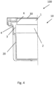
- Fig. 4 shows a filter arrangement 100 with a filter 10.
- the filter 10 is accommodated in a filter housing 20 as a filter receptacle.
- the circumferential sealing element 3 of the filter 10 lies with at least one of its outer
- Sealing surfaces 4 form a radial seal against the mating surfaces of the filter holder 20.
- the filter 10 is thus essentially leak-free to the filter holder 20.
- a cover 30 is provided, which is attached after the filter 10 has been installed in the filter holder 20. As indicated in the figure, the cover 20, the circumferential sealing element 3, and the filter holder 20 can be screwed together.
Landscapes
- Chemical & Material Sciences (AREA)
- Chemical Kinetics & Catalysis (AREA)
- Engineering & Computer Science (AREA)
- Life Sciences & Earth Sciences (AREA)
- Manufacturing & Machinery (AREA)
- Sustainable Development (AREA)
- Sustainable Energy (AREA)
- Electrochemistry (AREA)
- General Chemical & Material Sciences (AREA)
- Mechanical Engineering (AREA)
- Filtering Of Dispersed Particles In Gases (AREA)
Abstract
Description
- Die Erfindung betrifft einen Filter zum Reinigen eines Luftstroms mit zumindest einem ersten Filterelement für eine erste Filterstufe und einem zweiten Filterelement für einen zweite Filterstufe, wobei das zweite Filterelement mit einem umlaufenden Dichtelement versehen und das Dichtelement stoffschlüssig mit dem zweiten Filterelement verbunden ist.
- Aus dem Stand der Technik sind Filterelemente wie z.B. Taschenfilter, Kassettenfilter, Panelfilter, Kantenleimfilter oder Flachfilter bekannt. Sie werden zur Filtration von Fluiden, insbesondere von Luft, verwendet. Hierzu werden die Filterelemente üblicherweise in Filtergehäuse eingesetzt und mittels Befestigungselementen arretiert, z.B. verschraubt oder verrastet. Um eine effiziente Filtration zu gewährleisten, muss die Verbindung von Filter und Filterrahmen eine hohe Dichtigkeit aufweisen. Um diese zu gewährleisten, werden üblicherweise zusätzliche Dichtungen eingesetzt. Ein solcher Filter ist in der
EP 3 453 441 B1 beschrieben. - In der
DE 10 2013 011 457 A1 wird ein Filterelement für die Innenraumluft einer Fahrerkabine von Land- und Arbeitsmaschinen, insbesondere mit Spritz- oder Sprühvorrichtungen für Pflanzenschutz- oder Düngemittel beschrieben. Das Innenraumluftfilterelement umfasst eine Adsorptionsfilterlage mit Aktivkohle, eine Feinfilterlage, insbesondere zur Abscheidung von Aerosolen und eine umlaufende Dichtung zur Trennung der Rohgasseite von der Reingasseite beim Einbau in ein Filtergehäuse. - Bestehen die unterschiedlichen Filterstufen aus unterschiedlichen Filterelementen, so muss jedes Filterelement gegenüber dem aufnehmenden Filtergehäuse sicher abgedichtet werden. Auch muss bei der Montage aller Filterelemente darauf geachtet werden, dass die Dichtungen der Filterelemente nicht beschädigt werden.
- Aufgabe der vorliegenden Erfindung ist es, einen Filter zu schaffen, welcher mindestens zwei Filterelemente für mindestens zwei Filterstufen besitzt, eine materialsparsame Fertigung aufweist und eine einfache und sichere Montage in einer Filteraufnahme ermöglicht.
- Gelöst wird diese Aufgabe durch einen Filter wie er nachfolgend beschrieben und beansprucht ist.
- Erfindungsgemäß wurde als vorteilhaft erkannt, ein Dichtelement vorzusehen, welches eine Abdichtung des ersten Filterelements zum zweiten Filterelement und eine Abdichtung des zweiten Filterelements zur Filteraufnahme erlaubt.
- Der Filter dient zum Reinigen eines Luftstroms mit zumindest einem ersten Filterelement für eine erste Filterstufe und einem zweiten Filterelement für einen zweite Filterstufe. Das zweite Filterelement ist mit einem umlaufenden Dichtelement versehen, welches stoffschlüssig mit dem zweiten Filterelement verbunden ist. Die stoffschlüssige Verbindung der umlaufenden Dichtung kann z.B. durch Verkleben oder integrierte Fertigung realisiert sein, sodass eine sichere Abdichtung zwischen Filterelement und Filteraufnahme gewährleistet werden kann.
- Erfindungsgemäß weist das Dichtelement mindestens eine außenliegende, umlaufende Dichtfläche auf zur Abdichtung gegenüber einer Filteraufnahme. Somit korrespondiert die Form der Dichtfläche mit der Form der Filteraufnahme. Bei der Filteraufnahme kann es sich um ein Filtergehäuse oder um einen Luftkanal handeln. Die außenliegende, umlaufende Dichtfläche dient zur radialen Abdichtung des Filters zur Filteraufnahme. Radial meint dabei radial zur Erstreckung und Durchströmungsrichtung des Filters.
- Das Dichtelement weist in der Mitte eine Öffnung auf, durch welche bei der Filtration das zu filternde Fluid strömt und welche eine innenliegende, umlaufende Dichtfläche zur Abdichtung gegenüber dem ersten Filterelement aufweist. Das Dichtelement ist also derart ausgeformt, dass es sowohl das erste Filterelement als auch das zweite Filterelement rahmenartig umschließt. Mit nur einem Dichtelement wird so eine Abdichtung des ersten Filterelements zum zweiten Filterelement und eine Abdichtung des zweiten Filterelements zur Filteraufnahme erreicht.
- In einer vorteilhaften Weiterbildung der Erfindung ist das erste Filterelement in einem Presssitz in dem Dichtelement aufgenommen und die innenliegende Dichtfläche liegt mit einer Presspassung an dem ersten Filterelement an.
- Bevorzugt wird die innenliegende Dichtfläche des Dichtelements durch eine Dichtlippe gebildet.
- Die Dichtlippe kann in unverformtem Zustand, d.h. bevor das erste Filterelement in die Dichtung eingesetzt wird, eine Überlappung von mindestens 1 Millimeter gegenüber der Gegenfläche des ersten Filterelements besitzen. Das Dichtelement und das erste Filterelement sind kraftschlüssig miteinander verbunden. Dazu ist die Passung zwischen Dichtelement und erstem Filterelement so gewählt, dass ein Presssitz bzw. eine Presspassung gewährleistet wird. Eine Presspassung kann auch als Übermaßpassung bezeichnet werden. Der Presssitz gewährleistet dabei eine sichere Halterung des ersten Filterelements in seiner Montageposition auch bei mechanischen Beanspruchungen im Betrieb.
- Es wurde festgestellt, dass es vorteilhaft ist, das Dichtelement mit einer umlaufenden Kompensationsnut zu versehen, welche als anströmseitig angeordnete, umlaufende Vertiefung ausgebildet ist. Die Kompensationsnut kann vorteilhafterweise Rückstellungskräfte verringern. Insbesondere die Kombination von Dichtlippe und Kompensationsnut trägt zu einer leckagefreien Montage des Filters bei sehr hoher Dichtigkeit bei.
- In möglicher Ausgestaltung kann das Dichtelement an das zweite Filterelement angespritzt sein, d.h. als Spritzgussteil aus spritzgießfähigem Material ausgebildet sein, insbesondere aus Polyurethan oder Silikon.
- Es wurde herausgefunden, dass eine Shore-Härte A größer 20 des Materials des Dichtelements eine gute Abdichtung erlaubt. Die Shore-Härte A kann insbesondere im Bereich 20 bis 50 liegen, bei normgerechter Messungen nach DIN ISO 7619-1 oder ISO 868 oder ASTM D2240.
- In einer Ausführungsform des Filters ist das erste Filterelement und ggfs. auch das zweite Filterelement als umlaufend mit Kantenbändern versehener Faltenbalg aus einem plissierten Filtermedium ausgeführt. Hat das Filterelement in seiner Draufsicht eine rechteckige Form, dann ist es an seinen vier Seiten mit Kantenbändern versehen. Das erste Filterelement ist dabei derart ausgeführt, dass es eine gewisse Eigensteifigkeit besitzt, damit die umlaufenden Kantenbänder gut an der innenliegenden Dichtfläche anliegen und nicht von der Dichtfläche verformt werden.
- In Weiterbildung des Filters sind die Kanten der beiden Endfalten des Filtermediums des ersten Filterelements zu einer Anströmseite des Filters hin orientiert. Wird das erste Filterelement von einem zu reinigenden Luftstrom durchströmt, drückt der Luftstrom die jeweilige Endfalte des Filtermediums und das Kantenband radial nach außen und es wird eine entsprechende Kraft auf das Dichtelement ausgeübt.
- In einer Ausführungsform des Filters sind das erste Filterelement als ein Partikelfilterelement und/oder das zweite Filterelement als ein Adsorptionsfilterelement ausgebildet. Das Adsorptionsfilterelement kann als Adsorbens beispielsweise Aktivkohle aufweisen.
- Die Erfindung betrifft auch eine Filteranordnung mit einem Filter wie vorstehend beschrieben und einem Filtergehäuse zur Aufnahme des Filters.
- In Weiterbildung der Filteranordnung besitzt diese einen rahmenförmigen Deckel, welcher mit dem Filtergehäuse verbindbar ist, oder alternativ ein Gehäuseoberteil als Teil des Filtergehäuses, welche jeweils zum Fixieren des Filters im Filtergehäuse dienen. So kann auch verhindert werden, dass das erste Filterelement aus dem Dichtelement herausrutschen könnte.
- Die Erfindung betrifft auch die Verwendung einer Filteranordnung wie vorstehend beschrieben als Innenraumluftfilteranordnung zur Filtration und Reinigung der Kabinenzuluft in einem Fahrzeug oder als Zuluftfilter in einer Brennstoffzelleneinheit.
- Bei der Innenraumluftfilteranordnung erfolgt eine Filtration und Reinigung der Kabinenzuluft in einem Fahrzeug, welches einer erhöhten Schadstoffbelastung unterliegen kann, insbesondere in einem Nutzfahrzeug, einem Schwerlastfahrzeug oder einem Offroadfahrzeug. Bei den Fahrzeugen kann es sich beispielsweise handeln um Lastwagen, Baumaschinen, Walzen, Raupenfahrzeuge, Straßenfräsen, Planierraupen, Laderaupen, Bagger, Kräne, Erntemaschinen, Landmaschinen, Mähdrescher, Häcksler, Traktoren, selbstfahrende Feldspritzen, Forstfahrzeuge oder ähnliches.
- Die beschriebene Erfindung und die beschriebenen vorteilhaften Weiterbildungen der Erfindung stellen auch in Kombination miteinander - soweit dies technisch sinnvoll ist - vorteilhafte Weiterbildungen der Erfindung dar.
- Hinsichtlich weiterer Vorteile und in konstruktiver und funktioneller Hinsicht vorteilhafter Ausgestaltungen der Erfindung wird auf die Unteransprüche sowie die Beschreibung von Ausführungsbeispielen unter Bezugnahme auf die beiliegenden Figuren verwiesen.
- Die Erfindung soll anhand beigefügter Figuren noch näher erläutert werden. Einander entsprechende Elemente und Bauteile sind in den Figuren mit gleichen Bezugszeichen versehen. Zugunsten einer besseren Übersichtlichkeit der Figuren wurde auf eine maßstabsgetreue Darstellung verzichtet.
- Es zeigen in schematischer Darstellung
- Fig. 1a und b
- die Montage des Filters aus zwei Filterelementen
- Fig. 2a
- eine Ausführungsform eines Filters
- Fig. 2b
- eine Detailansicht des ersten Filterelements
- Fig. 3
- eine weitere Ausführungsform eines Filters
- Fig. 4
- eine Filteranordnung mit einem Filter
-
Fig. 1a und b zeigen die Montage des Filters 10 aus zwei Filterelementen 1, 2. InFig. 1a ist ein erstes Filterelement 1 dargestellt, welches in Montagerichtung M in ein umlaufendes Dichtelement 3 eingeschoben wird, welches sich an einem zweiten Filterelement 2 befindet. InFig. 1b ist der Filter 10 in fertig montiertem Zustand dargestellt. Erstes Filterelement 1 und zweites Filterelement 2 sind über das umlaufende Dichtelement 3 miteinander verbunden. Das erste Filterelement 1 ist an seinen Rändern mit Kantenbändern 9 versehen. Das umlaufende Dichtelement 3 weist eine innenliegende Dichtfläche 5 auf. Mit den Außenflächen seiner Kantenbänder 9 kommt das erste Filterelement 1 an der innenliegenden Dichtfläche 5 dichtend zur Anlage. Damit das erste Filterelement 1 sicher in dem umlaufenden Dichtelement 3 hält, können die Abmaße von erstem Filterelement 1 und der innenliegenden Dichtfläche 5 so aufeinander abgestimmt sein, dass eine Presspassung realisiert wird. - Das umlaufende Dichtelement 3 ist mit dem zweiten Filterelement 2 stoffschlüssig verbunden, z.B. verklebt.
- Das umlaufende Dichtelement 3 besitzt eine weitere Dichtfläche, nämlich eine außenliegende Dichtfläche 4. Diese dient der Abdichtung des Filters 10 gegenüber einer hier nicht dargestellten Filteraufnahme 20.
-
Fig. 2a zeigt eine zweite Ausführungsform eines Filters 10. Wie auch beim vorstehend beschriebenen Beispiel sind das umlaufende Dichtelement 3 und das zweite Filterelement 2 stoffschlüssig miteinander verbunden und das erste Filterelement 1 wird in einer Presspassung in dem umlaufenden Dichtelement 3 aufgenommen. Zur Realisierung der Presspassung weist die als Dichtlippe 6 ausgestaltete innenliegende Dichtfläche 5 gegenüber der Gegenfläche des ersten Filterelements 1 eine Überlappung u auf. Dies gilt für die unverformte Dichtlippe 6 vor dem Einschieben des ersten Filterelements 1 in das umlaufende Dichtelement 3. Im dargestellten Ausführungsbeispiel ist die Überlappung u größer als 1mm. Zum besseren Verständnis und für eine eindeutige Darstellbarkeit ist die Dichtlippe in derFig. 2a im unverformten Zustand dargestellt. - Der Filter 10 wird von einem Luftstrom L von einer Anströmseite A hin zu einer Abströmseite B durchströmt und der Luftstrom L dabei gereinigt.
- Das umlaufende Dichtelement 3 weist auf seiner Anströmseite eine Kompensationsnut 7 auf, also eine Vertiefung.
-
Fig. 2b zeigt eine Detailansicht des ersten Filterelements 1, wie es in den Filtern 10 derFiguren 1a-b und2a und4 zum Einsatz kommt. Das erste Filterelement 1 besitzt einen Faltenbalg 11 aus einem plissierten Filtermedium, z.B. aus Vliesstoff. An den Endfalten 8 und den Seitenflächen des Faltenbalgs 11 ist dieser mit Kantenbändern 9 versehen. Die Kanten der beiden Endfalten 8 sind zur Anströmseite A hin orientiert. Auch das zweite Filterelement 2 kann einen vierseitig mit Kantenbändern 9 versehenen Faltenbalg 11 besitzen. -
Fig. 3 zeigt eine weitere Ausführungsform eines Filters 10. Erstes und zweites Filterelement 1 und 2 können auch andere Ausgestaltungen aufweisen und beispielsweise als geschäumter oder wabenförmiger Filterkörper, als extrudiertes Adsorptionselement z.B. als Aktivkohle-Honeycombs ausgestaltet sein. Auch für das umlaufende Dichtelement 3 sind unterschiedlichste Ausformungen denkbar. -
Fig. 4 zeigt eine Filteranordnung 100 mit einem Filter 10. Der Filter 10 ist in einem Filtergehäuse 20 als Filteraufnahme aufgenommen. Das umlaufende Dichtelement 3 des Filters 10 liegt zumindest mit einer seiner außenliegenden - Dichtflächen 4 radial dichtend an Gegenflächen der Filteraufnahme 20 an. Der Filter 10 ist so im Wesentlichen leckagefrei zur Filteraufnahme 20.
- Um den Filter 10 mit dem ersten Filterelement 1 auch bei evtl. Erschütterungen sicher in der Filteraufnahme 20 zu halten ist ein Deckel 30 vorgesehen, welche nach Montage des Filters 10 in die Filteraufnahme 20 angebracht wird. Wie in der Figur angedeutet können der Deckel 20, das umlaufende Dichtelement 3 und die Filteraufnahme 20 miteinander verschraubt sein.
-
- 1
- erstes Filterelement
- 2
- zweites Filterelement
- 3
- umlaufendes Dichtelement
- 4
- außenliegende Dichtfläche
- 5
- innenliegende Dichtfläche
- 6
- Dichtlippe
- 7
- Kompensationsnut
- 8
- Endfalte
- 9
- Kantenband
- 10
- Filter
- 11
- Faltenbalg aus Filtermedium
- 20
- Filteraufnahme (z.B. Filtergehäuse)
- 30
- Deckel
- 100
- Filteranordnung
- A
- Anströmseite / Rohgasseite
- B
- Abströmseite / Reingasseite
- L
- Luftstrom
- M
- Montagerichtung
- u
- Überlappung
Claims (13)
- Filter (10) zum Reinigen eines Luftstroms (L) mit zumindest einem ersten Filterelement (1) für eine erste Filterstufe und einem zweiten Filterelement (2) für einen zweite Filterstufe, wobei das zweite Filterelement (2) mit einem umlaufenden Dichtelement (3) versehen und das Dichtelement (3) stoffschlüssig mit dem zweiten Filterelement (2) verbunden ist,
dadurch gekennzeichnet, dassdas Dichtelement (3) aufweisteine außenliegende, umlaufende Dichtfläche (4) zur Abdichtung gegenüber einer Filteraufnahme (20) undeine innenliegende, umlaufende Dichtfläche (5) zur Abdichtung gegenüber dem ersten Filterelement (1). - Filter nach Anspruch 1
dadurch gekennzeichnet, dass
das erste Filterelement (1) in einem Presssitz in dem Dichtelement (3) aufgenommen ist. - Filter nach einem der vorangehenden Ansprüche
dadurch gekennzeichnet, dass
die innenliegende Dichtfläche (5) des Dichtelements (3) durch eine Dichtlippe (6) gebildet wird. - Filter nach Anspruch 2 und 3
dadurch gekennzeichnet, dass
die Dichtlippe (6) in unverformtem Zustand eine Überlappung von mindestens 1 Millimeter gegenüber der Gegenfläche des ersten Filterelements (1) besitzt. - Filter nach einem der vorangehenden Ansprüche
dadurch gekennzeichnet, dass
das Dichtelement (3) eine umlaufende Kompensationsnut (7) aufweist, welche als anströmseitig angeordnete, umlaufende Vertiefung ausgebildet ist. - Filter nach einem der vorangehenden Ansprüche
dadurch gekennzeichnet, dass
das Dichtelement (3) an das zweite Filterelement (2) angespritzt ist und insbesondere aus Polyurethan oder Silikon ist. - Filter nach einem der vorangehenden Ansprüche
dadurch gekennzeichnet, dass
das Material des Dichtelements (3) eine Shore-Härte A größer 20 aufweist, insbesondere im Bereich 20 bis 50. - Filter nach einem der vorangehenden Ansprüche
dadurch gekennzeichnet, dass
das erste Filterelement (1) als umlaufend mit Kantenbändern (9) versehener Faltenbalg (11) aus einem plissierten Filtermedium ausgeführt ist. - Filter nach Anspruch 8
dadurch gekennzeichnet, dass
die Kanten der beiden Endfalten (8) des Filtermediums des ersten Filterelements (1) zu einer Anströmseite (A) des Filters (10) hin orientiert sind. - Filter nach einem der vorangehenden Ansprüche
dadurch gekennzeichnet, dass
das erste Filterelement (1) als ein Partikelfilterelement und/oder das zweite Filterelement (2) als ein Adsorptionsfilterelement ausgebildet sind. - Filteranordnung (100) mit einem Filter (10) nach einem der vorangehenden Ansprüche und einem Filtergehäuse (20) zur Aufnahme des Filters (10).
- Filteranordnung nach Anspruch 11
dadurch gekennzeichnet, dass
diese einen rahmenförmigen Deckel (30), welcher mit dem Filtergehäuse (20) verbindbar ist, oder ein Gehäuseoberteil als Teil des Filtergehäuses (20), besitzt, zum Fixieren des Filters (10) im Filtergehäuse (20). - Verwendung einer Filteranordnung (100) nach einem der Ansprüche 11 oder 12 als Innenraumluftfilteranordnung zur Filtration und Reinigung der Kabinenzuluft in einem Fahrzeug oder als Zuluftfilter in einer Brennstoffzelleneinheit.
Priority Applications (2)
| Application Number | Priority Date | Filing Date | Title |
|---|---|---|---|
| EP23199850.1A EP4529971A1 (de) | 2023-09-26 | 2023-09-26 | Filter mit umlaufendem dichtelement |
| US18/806,752 US20250099889A1 (en) | 2023-09-26 | 2024-08-16 | Filter having a circumferential sealing element |
Applications Claiming Priority (1)
| Application Number | Priority Date | Filing Date | Title |
|---|---|---|---|
| EP23199850.1A EP4529971A1 (de) | 2023-09-26 | 2023-09-26 | Filter mit umlaufendem dichtelement |
Publications (1)
| Publication Number | Publication Date |
|---|---|
| EP4529971A1 true EP4529971A1 (de) | 2025-04-02 |
Family
ID=88204184
Family Applications (1)
| Application Number | Title | Priority Date | Filing Date |
|---|---|---|---|
| EP23199850.1A Pending EP4529971A1 (de) | 2023-09-26 | 2023-09-26 | Filter mit umlaufendem dichtelement |
Country Status (2)
| Country | Link |
|---|---|
| US (1) | US20250099889A1 (de) |
| EP (1) | EP4529971A1 (de) |
Families Citing this family (1)
| Publication number | Priority date | Publication date | Assignee | Title |
|---|---|---|---|---|
| USD884866S1 (en) * | 2018-05-08 | 2020-05-19 | Cummins Filtration Ip, Inc. | Filter element |
Citations (4)
| Publication number | Priority date | Publication date | Assignee | Title |
|---|---|---|---|---|
| EP0723800A1 (de) * | 1995-01-26 | 1996-07-31 | Firma Carl Freudenberg | Kassettenfilter |
| DE102013011457A1 (de) | 2012-07-11 | 2014-01-16 | Mann + Hummel Gmbh | Luftfilter für die Innenraumluft von Kabinen von Fahrzeugen, Land-, Bau- und Arbeitsmaschinen |
| US20160114275A1 (en) * | 2013-06-06 | 2016-04-28 | Cummins Filtration Ip, Inc. | Air filter with improved performance or positioning |
| EP3453441B1 (de) | 2017-09-07 | 2020-09-02 | Carl Freudenberg KG | Taschenfilterelement |
-
2023
- 2023-09-26 EP EP23199850.1A patent/EP4529971A1/de active Pending
-
2024
- 2024-08-16 US US18/806,752 patent/US20250099889A1/en active Pending
Patent Citations (4)
| Publication number | Priority date | Publication date | Assignee | Title |
|---|---|---|---|---|
| EP0723800A1 (de) * | 1995-01-26 | 1996-07-31 | Firma Carl Freudenberg | Kassettenfilter |
| DE102013011457A1 (de) | 2012-07-11 | 2014-01-16 | Mann + Hummel Gmbh | Luftfilter für die Innenraumluft von Kabinen von Fahrzeugen, Land-, Bau- und Arbeitsmaschinen |
| US20160114275A1 (en) * | 2013-06-06 | 2016-04-28 | Cummins Filtration Ip, Inc. | Air filter with improved performance or positioning |
| EP3453441B1 (de) | 2017-09-07 | 2020-09-02 | Carl Freudenberg KG | Taschenfilterelement |
Also Published As
| Publication number | Publication date |
|---|---|
| US20250099889A1 (en) | 2025-03-27 |
Similar Documents
| Publication | Publication Date | Title |
|---|---|---|
| EP4308807B1 (de) | Filterelement und filtersystem | |
| DE102014004220A1 (de) | Innenraumluftfilterelement | |
| EP4251299B1 (de) | Filter, insbesondere innenraumfilter eines kraftfahrzeugs, verwendung eines filterelements in dem filter und kraftfahrzeug | |
| EP2227307A1 (de) | Filterelement und filtersystem | |
| DE102009009066A1 (de) | Filtereinrichtung zur Filtration gasförmiger Fluide | |
| DE102014006852A1 (de) | Hohlfilterelement, Filtergehäuse und Filter | |
| WO2014154484A2 (de) | Filterelement mit abstützelementen, filter mit einem filterelement und filtergehäuse eines filters | |
| EP3520878A1 (de) | Filterelement und verwendung eines solchen filterelements | |
| DE102016004316A1 (de) | Filterelement und Filteranordnung | |
| DE102014009706A1 (de) | Filterelement mit Halteflächen, Filter mit einem Filterelement und Filtergehäuse eines Filters | |
| DE19736290A1 (de) | Filteranordnung sowie Verfahren zu deren Herstellung | |
| EP1733778B1 (de) | Luftfilter | |
| EP4529971A1 (de) | Filter mit umlaufendem dichtelement | |
| DE102005029750A1 (de) | Filterdichtsystem | |
| EP4316629A1 (de) | Sekundärelement und filtersystem | |
| DE19922326B4 (de) | Mehrlagiges Filtermedium | |
| WO2025083194A1 (de) | Filterelement zum filtern eines gasförmigen fluids | |
| EP4124374A1 (de) | Filteranordnung mit filter in einem gehäuse | |
| WO2025108671A1 (de) | Filterelement, insbesondere zur gasfiltration | |
| WO2024074258A1 (de) | Filterelement und filtervorrichtung | |
| EP4166214B1 (de) | Filteranordnung mit codierelement | |
| DE102021126855A1 (de) | Filterelement und Filtersystem | |
| EP1638665B1 (de) | Filter für das getriebeöl in automatikgetrieben von kraftfahrzeugen | |
| DE102019124432A1 (de) | Fluid-Reinigungselement eines Fluid-Reinigungssystems zum Reinigen von flüssigem Fluid, Fluid-Reinigungssystem und Dichtelement eines Fluid-Reinigungselements | |
| DE102023114807A1 (de) | Flachfilter-Filterelement mit wenigstens zwei Filtermediumkörpern, Filtersystem und Verwendung eines Flachfilter-Filterelements |
Legal Events
| Date | Code | Title | Description |
|---|---|---|---|
| PUAI | Public reference made under article 153(3) epc to a published international application that has entered the european phase |
Free format text: ORIGINAL CODE: 0009012 |
|
| STAA | Information on the status of an ep patent application or granted ep patent |
Free format text: STATUS: THE APPLICATION HAS BEEN PUBLISHED |
|
| AK | Designated contracting states |
Kind code of ref document: A1 Designated state(s): AL AT BE BG CH CY CZ DE DK EE ES FI FR GB GR HR HU IE IS IT LI LT LU LV MC ME MK MT NL NO PL PT RO RS SE SI SK SM TR |
|
| STAA | Information on the status of an ep patent application or granted ep patent |
Free format text: STATUS: REQUEST FOR EXAMINATION WAS MADE |
|
| 17P | Request for examination filed |
Effective date: 20250521 |
|
| STAA | Information on the status of an ep patent application or granted ep patent |
Free format text: STATUS: EXAMINATION IS IN PROGRESS |
|
| 17Q | First examination report despatched |
Effective date: 20250812 |