EP4529818A1 - Automatic coffee bean grinder - Google Patents
Automatic coffee bean grinder Download PDFInfo
- Publication number
- EP4529818A1 EP4529818A1 EP23200893.8A EP23200893A EP4529818A1 EP 4529818 A1 EP4529818 A1 EP 4529818A1 EP 23200893 A EP23200893 A EP 23200893A EP 4529818 A1 EP4529818 A1 EP 4529818A1
- Authority
- EP
- European Patent Office
- Prior art keywords
- grinder
- motor
- adjustment
- way
- machine shaft
- Prior art date
- Legal status (The legal status is an assumption and is not a legal conclusion. Google has not performed a legal analysis and makes no representation as to the accuracy of the status listed.)
- Granted
Links
Images




Classifications
-
- A—HUMAN NECESSITIES
- A47—FURNITURE; DOMESTIC ARTICLES OR APPLIANCES; COFFEE MILLS; SPICE MILLS; SUCTION CLEANERS IN GENERAL
- A47J—KITCHEN EQUIPMENT; COFFEE MILLS; SPICE MILLS; APPARATUS FOR MAKING BEVERAGES
- A47J42/00—Coffee mills; Spice mills
- A47J42/12—Coffee mills; Spice mills having grinding discs
- A47J42/18—Adjusting mechanisms
-
- A—HUMAN NECESSITIES
- A47—FURNITURE; DOMESTIC ARTICLES OR APPLIANCES; COFFEE MILLS; SPICE MILLS; SUCTION CLEANERS IN GENERAL
- A47J—KITCHEN EQUIPMENT; COFFEE MILLS; SPICE MILLS; APPARATUS FOR MAKING BEVERAGES
- A47J42/00—Coffee mills; Spice mills
- A47J42/12—Coffee mills; Spice mills having grinding discs
- A47J42/16—Coffee mills; Spice mills having grinding discs mechanically driven
-
- A—HUMAN NECESSITIES
- A47—FURNITURE; DOMESTIC ARTICLES OR APPLIANCES; COFFEE MILLS; SPICE MILLS; SUCTION CLEANERS IN GENERAL
- A47J—KITCHEN EQUIPMENT; COFFEE MILLS; SPICE MILLS; APPARATUS FOR MAKING BEVERAGES
- A47J42/00—Coffee mills; Spice mills
- A47J42/38—Parts or details
Definitions
- the present invention relates to a coffee bean grinder, which is easy to manufacture, robust, and which is in particular easy to service and/or clean in a way of avoiding problems associated with improper and unexperienced handling. It also relates to methods of manufacturing corresponding grinders and methods of servicing and/or cleaning corresponding grinders, as well as uses of such grinders.
- Coffee grinders or grinding groups in machines that dispense coffee beverages comprise a container of coffee beans, connected to a grinding chamber into which the beans flow and are transformed into ground coffee, and a subsequent system for conveying the ground beans to an infusion or portioning system for the sale of the coffee in a beverage or ground form.
- the ground coffee in said grinding chamber is not characterized by particles of uniform geometry but by a distribution of such geometry (particle size distribution) which is highly variable depending both on the distance between the grinding tools through which the coffee bean passes (called mills) and on other factors such as the degree of roasting of the bean, the temperature at which the grinding takes place, the geometry of the mill itself or of the cutting edges thereof, the quality of the cutting edge of the mill, the speed of rotation of the tools, etc., all of which affect the grinding mechanics.
- Coffee grinders exist and are well-established wherein the distance between the mills that grind the beans is adjusted by means of a screw/nut screw coupling that puts one of the two grinding elements of the mill in position with respect to the other.
- the adjustment of the distance between the grinding elements is therefore carried out by means of members that, rotating by means of the screw/nut screw coupling, cause an axial shift (modification of the distance) of one of the two grinding elements.
- One of the grinding elements in such coffee grinders is mounted stationary, and the other grinding element is mounted in a rotating way, and is driven by a motor.
- the load on the grinding parts is enormous, since during grinding high temperatures can be achieved, the grinding generates a lot of friction and torque, and in addition to that the rotating and adjustable parts are subject to getting dirty by fine particles penetrating into smallest gaps.
- regular cleaning and maintenance including for example also replacement of grinding elements, is important and is a key factor for high ground coffee quality. There is therefore a desire to have the possibility of easy access to the grinding elements, so as to simplify the cleaning and/or servicing process.
- EP-A-3824776 discloses a grinder-doser apparatus with removable grinding chamber for extraction, with fast release; the proposed solution makes the grinding adjustment independent of the access to the grinding chamber and makes maintenance easier for the operator.
- An interface flange is provided which is interposed in univocal position between the adjusting ring nut and the fixed structure of the chamber, which flange makes the coupling indirect of the ring nut and of the extractable group to said fixed structure, being screwed into said flange which is instead slidingly inserted.
- the locking involves a hooking and releasing system of fast and tensioned type, by means of levers with cam tooth mounted externally on said interface flange, which engage hooking the head of respective tie-rod groups with elastic spring, putting them in traction, which are joined to said fixed structure of the chamber.
- the present invention relates to a grinder as defined in claim 1 as well as to methods and uses as defined in the further claims.
- a coffee grinder with a grinder motor and a grinder unit with a rotating grinder element and a stationary grinder element, the distance of which (grinder gap width for the grinding degree adjustment) can be manually adjusted by using a manual adjustment element and/or automatically adjusted by way of a grinder adjustment motor.
- the grinder motor and the grinder unit are located in a first portion of the grinder and the adjustment element and the grinder adjustment motor are mounted in a second portion of the grinder, and in that the first portion is fixedly mounted on a stand and the second portion is attached to the first portion by way of hinge, said hinge allowing to tilt the second portion from
- the axis of said hinge is arranged in a vertical direction, and preferably the axis is located in or at a protrusion of the second portion protruding from the second portion in the direction of the first portion.
- the vertical axis is mounted in or on the first portion in a slidable way, preferably slidable along a direction perpendicular to a contact plane between the first portion and the second portion in the closed position, and wherein further preferably the slidable mounting is provided in or on protrusions protruding from the first portion along said direction perpendicular to the contact plane, preferably implemented with slots as described further below.
- a locking mechanism for locking the second portion in the closed position, wherein further preferably said locking mechanism is based on form closure and/or force closure and preferably is selected from the group consisting of bayonet locking, lever lock, hook lock, screwing or a combination thereof.
- the locking mechanism can at least partly be located essentially opposite to the location of the hinge.
- the locking mechanism can be provided in that the second portion is provided with engagement elements, preferably with engagement screws (preferably radially offset from the machine shaft axis and e.g. circumferentially distributed), which in the closed position are oriented essentially parallel to a machine shaft axis of the grinder motor, which engagement elements in the closed position engage, preferably threadingly, in complementary engagement means, preferably in the form of engagement interior threadings provided in or on the first portion.
- engagement elements preferably with engagement screws (preferably radially offset from the machine shaft axis and e.g. circumferentially distributed), which in the closed position are oriented essentially parallel to a machine shaft axis of the grinder motor, which engagement elements in the closed position engage, preferably threadingly, in complementary engagement means, preferably in the form of engagement interior threadings provided in or on the first portion.
- the engagement elements and the complementary engagement means are provided in a contacting interface portion of the first portion and of the second portion, such that in the closed position the engagement elements and the complementary engagement means are buried within the housing of the first portion and the second portion.
- the engagement screws can e.g. be made accessible for loosening by removal of a front face plate of the front portion.
- the second portion comprises at least one bearing acting as a bearing for a tip portion of the machine shaft, wherein this bearing is axially slidably mounted in the front portion but axially fixed in a direction to the back portion to the axially slidable machine shaft in the closed position.
- the adjustment element can be an adjustment wheel rotatably mounted in the second portion with a horizontal rotation axis and preferably facing a front side of the grinder.
- the grinder adjustment motor can be located in the front portion, and the grinder adjustment motor shaft is parallel to the motor shaft but radially offset to the motor shaft.
- a gear wheel which is coaxial with the machine shaft, which gear wheel is mounted such that upon rotation of the gear wheel the gear wheel is displaced relative to the front portion in an axial direction, and wherein the axial displacement of the gear wheel is directly or indirectly coupled to the axially slidably mounted machine shaft and in particular to a rotating grinder plate mounting mounted on the machine shaft and carrying the rotating grinder plate, for adjustment of the gap width of the grinder unit.
- the gear wheel can be rotating for gap width adjustment by way of the manual grinder adjustment wheel as well as by way of the grinder motor, wherein preferably the gear wheel is provided with an external toothing cooperating with an outer threading of the motor shaft of the grinder adjustment motor.
- the grinder comprises a vertical stand on a baseplate and wherein in the closed position said first portion and said second portion are aligned coaxially and horizontally and the grinder motor is mounted in said first portion with its machine shaft being arranged horizontally and preferably coaxially with said first and second portion.
- the grinder unit may comprise a rotating grinder element in the form of a grinding ring mounted on a rotating grinder plate mounting which is coupled to the machine shaft of the motor, and a stationary grinder element also in the form of a grinding ring mounted in or on a stationary grinder plate mounting, and wherein in the open position the rotating grinder plate mounting can be directly accessed.
- the rotating grinder plate mounting can be fixed to the machine shaft of the grinder motor by way of an attachment element which can be directly accessed in the open position.
- the machine shaft of the grinder motor is slidably mounted and biased in a direction towards the front portion, preferably by way of a spring in a bearing of the machine shaft.
- the present invention relates to a method of servicing and/or cleaning a grinder according to the above, wherein for servicing and/or cleaning the grinder it is brought from the closed position to the open position, and the grinder unit and/or the interior elements of the front portion is accessed and cleaned and/or disassembled and/or serviced in that open position, reassembled and then brought into the closed position.
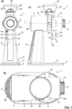
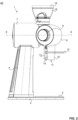
- a grinder embodying elements of the invention is shown in the closed position, and in Fig. 2 the same grinder is shown in the open position.
- the same reference numerals indicate the same structural elements in the figures.
- the grinder 1 comprises a base plate 2 with a collection dish 3 in a front portion thereof and below an outlet opening 11 of the grinder. On that base plate 2 in the backside area there is located a vertical stand 4, which may contain electronics, power supply and, in this case, on the lateral side is provided with the main switch 5.
- That horizontal part 6 is composed of a back portion 7 with an essentially cylindrical housing, in which back portion 7 the grinder motor 25 is located with its motor shaft 27 oriented in a horizontal orientation and pointing into the front direction.
- the horizontal part 6 is further comprising a front portion 8, and that front portion also comprises an essentially cylindrical housing and is arranged coaxially with the back portion 7.
- a coffee bean hopper 18 in the form of a funnel, comprising a lid 19 and enclosing an interior space 22 to take up the coffee beans to be ground.
- distribution elements 20, stationary or rotating, in that interior space 22 can be provided.
- the hopper 18 opens into a channel leading into the actual grinder unit.
- the back portion 7 is closed by a back cover 26, and to the front side of the front portion 8 this is provided with a front face plate 24, in the region of which, coaxially with the motor shaft 27, the manual grinder adjustment wheel 9 is mounted.
- the adjustment wheel 9 comprises, on its outer circumferential cylindrical surface, axial ribs and/or indentations for ease of handling.
- the overarching front portion is provided with an outlet tube or duct 10, having an outlet opening 11, through which the ground coffee exits the grinder, typically into a filter holder which can be attached in that phase to the grinder.
- a filter holder mounting mechanism comprising a lever 12, with a crossbar 13, which on the top is provided with a coil spring 14 and on the bottom with an engagement portion 15, and which is tiltable mounted around axis 39.
- the lever comprises two circumferential arms 16 traveling around the duct 10. Attaching the filter holder to that mechanism can either take place by auto-engagement (self-engaging) with form-closure upon approach of the filter holder from the bottom, or it can take place by active manipulation of the lever 12 by the user.
- the middle portion of the machine shaft 27 is mounted in that stationary grinder plate mounting 31 by way of a middle bearing 28, allowing the machine shaft 27 to rotate but also to slide axially in that middle bearing 28 to a certain extent.
- the motor shaft 27 On its backside, the motor shaft 27 is mounted on the backside end of the actual motor block by way of a backside bearing 53.
- the motor shaft 27 In that backside bearing 53, the motor shaft 27 is rotatably mounted in an axially slidable way within defined limits, the extent of which essentially defines the limits of the axial displacement allowed for the adjustment of the gap of the grinder.
- this backside bearing is provided with a spiral spring, which presses the machine shaft 27 in the direction of the front portion 8 of the grinder. This means that in the absence of any counterforce, the motor shaft 27 will be displaced as much as possible and in as far as allowed by corresponding abutment positions of the machine shaft 27 in the direction of the front portion 8, and the gap of the grinder, i.e. the distance between the burrs 30 and 32 will be maximal.
- the stationary grinder plate mounting 31 In the direction of the front portion 8 the stationary grinder plate mounting 31 is followed by the rotating grinder plate mounting 29, which is fixed to a front portion (but not the very tip thereof) of the shaft 27, for example by way of a screw 46.
- This rotating grinder plate mounting 29 carries the rotating grinder plate or burr 30, which is opposite to the stationary grinder plate 32, such that between these two grinder elements the grinding cavity 36 is defined.
- the front portion 8 follows on that rotating grinder plate mounting 29 in that it comprises as a first element a front side bearing 34, which acts as bearing of the tip portion 45 of the shaft 27.
- This front side bearing 34 is in itself slidably mounted in the front portion 8, and in the closed position it abuts with a front surface or front contour 54 of the rotating grinder plate mounting.
- a front surface or front contour 54 of the rotating grinder plate mounting By way of an axial force in the backside direction of this slidable front side bearing 34 onto the rotating grinder plate mounting 29, the axial position of the machine shaft 27 and correspondingly the width of the gap of the grinder is defined against the force of the spiral spring mentioned above located in the back side bearing 53.
- the front portion 8 is mounted on the back portion 7 by way of a hinge, which is located at the tip of a hinge protrusion 23 provided on the front portion 8 and pointing horizontally in the direction of the back portion 7 in the form of a tab.
- This mounting is advantageous to make sure that in the initial phase of the opening the opening direction of the front portion 8 relative to the back portion 7 is as coaxial as possible.
- the axis 33 of that hinge is arranged vertically and slightly offset to the inside relative to the outline of the housing.
- an entry opening 43 which opens into the interior of the outlet tube 10 for the discharge of the ground coffee.
- an upper protrusion 49 as well as a lower protrusion 38.
- the upper protrusion 49 and the lower protrusion 38 contain an axial guide (i.e. extending in a direction parallel to the extension direction of the protrusions 38 and 49, i.e. perpendicular to the contact plane in the closed position illustrated by the dashed line 74 schematically in Fig. 1c and e ) for the front unit 7.
- the axial guide can be provided provided as a slot open towards the bottom in the upper protrusion 49 and a parallel corresponding slot open towards the upper side in the lower protrusion 38, and the axis 33 is sliding in that slot.
- the axis can be mounted at both (upper and lower) ends in a corresponding axis mounting nut which itself is sliding in the upper or lower slot, respectively.
- the upper and the lower slot can be provided as an undercut groove or dovetail groove with lateral projections at the exit of the slot, and the mounting nut for the axis 33 can be provided with lateral grooves engaging in the lateral projections of the slots in the protrusions 49 and 38.
- the four screws 41/42 are loosened, then the head unit 7 is pulled forward towards by the operator and away from the rear part 6 of the grinder along the slots in the upper protrusion 49 and the lower protrusion 38. Once fully extended, the user is then able to swing open the head unit 7 "like a door".
- the grinder adjustment wheel 9 for the manual adjustment comprises a circumferential surface with the above-mentioned ribs 17.
- a front plate 56 which in this case is at least partially transparent, such that a display unit 56 which is located behind can represent information through that front plate 56: for example information about the gap width, the grinding degree, the temperature, humidity, or the type of coffee for which the beans are ground, or a combination of such information.
- the grinder adjustment wheel 9 comprises a portion which penetrates behind the front face plate 24 and which has an engagement flange 57, attached to and cooperating with a ring-like attachment plate 62. That attachment plate 62 comprises engagement openings 61, into which engagement protrusions 58, which axially protrude from a gear wheel 59, slidingly engage.
- the gear wheel 59 comprises an radially external toothing 60, and itself is rotatably mounted in being fixed by way of interior portion 73 to the outer part 63 of a threaded hub.
- That outer part 63 of the threaded hub is rotatably and by way of a threading mounted on an inner part 64 of the threaded hub, which in turn is stationary and which is firmly attached to a portion of the interior mounting structure 65 as well as to a radial wall 71.
- an axially slidable outer bearing 66 which is coupled to the outer part 63 of the threaded hub and/or the interior portion 73 of the gear wheel 59.
- the outer bearing 66 is coupled in an axial direction to the front side bearing 34 by way of three circumferentially distributed, slidable adjustment pins (not illustrated in Fig. 1f ) ), which penetrate through through-openings 70 in the stationary radial wall 72.
- a motor 67 for the automatic grinder gap adjustment is also located in the front portion 8 . That motor 67 is arranged with its shaft 68 parallel to the machine shaft 27, but offset in a lateral direction, and the shaft 68 is provided with an outer threading 69 or rather with a shaft element providing that outer threading.
- the outer threading 69 cooperates with the external toothing 60 of the gear wheel 59.
- the motion train for manual adjustment is as follows: if the user manipulates the grinder adjustment wheel 9, that rotational motion is transferred via the engagement flange 57, the attachment plate 62, the axially sliding but rotationally fixed engagement between the engagement protrusions 58 and the engagement openings 61, to a corresponding rotation of the gear wheel 59.
- Rotation of the gear wheel 59 due to the threading of the threaded hub and the rotation of the outer part 63 relative to the stationary inner part 64 thereof, leads to an axial displacement of the outer part 63 as well as of the gear wheel 59 and the interior portion 73 of the gear wheel 59.
Landscapes
- Engineering & Computer Science (AREA)
- Mechanical Engineering (AREA)
- Food Science & Technology (AREA)
- Crushing And Pulverization Processes (AREA)
Abstract
characterized in that the motor and the grinder unit are located in a first portion (7) of the grinder (1) and the adjustment element (9) is mounted in a second portion (8) of the grinder, and in that the first portion (7) is fixedly mounted on a stand (4) and the second portion (8) is attached to the first portion (7) by way of hinge, said hinge allowing to tilt the second portion (8) from a closed position, in which the first portion (7) is located adjacent to the second portion (8), and where the first portion (7) and the second portion (8) are engaged in a way such that by way of the adjustment element (9) the distance of the grinder elements (30, 31) can be adjusted, to an open position, in which the second portion (8) is panned away from the first portion (7) and where direct access is given to the grinder unit.
Description
- The present invention relates to a coffee bean grinder, which is easy to manufacture, robust, and which is in particular easy to service and/or clean in a way of avoiding problems associated with improper and unexperienced handling. It also relates to methods of manufacturing corresponding grinders and methods of servicing and/or cleaning corresponding grinders, as well as uses of such grinders.
- Coffee grinders or grinding groups in machines that dispense coffee beverages comprise a container of coffee beans, connected to a grinding chamber into which the beans flow and are transformed into ground coffee, and a subsequent system for conveying the ground beans to an infusion or portioning system for the sale of the coffee in a beverage or ground form.
- The ground coffee in said grinding chamber is not characterized by particles of uniform geometry but by a distribution of such geometry (particle size distribution) which is highly variable depending both on the distance between the grinding tools through which the coffee bean passes (called mills) and on other factors such as the degree of roasting of the bean, the temperature at which the grinding takes place, the geometry of the mill itself or of the cutting edges thereof, the quality of the cutting edge of the mill, the speed of rotation of the tools, etc., all of which affect the grinding mechanics.
- Coffee grinders exist and are well-established wherein the distance between the mills that grind the beans is adjusted by means of a screw/nut screw coupling that puts one of the two grinding elements of the mill in position with respect to the other.
- The adjustment of the distance between the grinding elements is therefore carried out by means of members that, rotating by means of the screw/nut screw coupling, cause an axial shift (modification of the distance) of one of the two grinding elements.
- Once the optimal degree of fineness of the ground coffee has been defined, subsequent adjustments to the relative position between the grinding elements are often required in the course of the day or on subsequent days, as there are many aspects that, with the same positioning of the grinding elements, may affect the particle size distribution of the ground coffee.
- One of the grinding elements in such coffee grinders is mounted stationary, and the other grinding element is mounted in a rotating way, and is driven by a motor. The load on the grinding parts is enormous, since during grinding high temperatures can be achieved, the grinding generates a lot of friction and torque, and in addition to that the rotating and adjustable parts are subject to getting dirty by fine particles penetrating into smallest gaps. Correspondingly regular cleaning and maintenance, including for example also replacement of grinding elements, is important and is a key factor for high ground coffee quality. There is therefore a desire to have the possibility of easy access to the grinding elements, so as to simplify the cleaning and/or servicing process. On the other hand in order to have a powerful and reliable system, which in particular is not prone to grinding gap changes during use, the parts need to be very firmly fixed in space. These are conflicting requirements, since any ease of access will often go to the detriment of the rigidity of the structure.
-
EP-A-3824776 discloses a grinder-doser apparatus with removable grinding chamber for extraction, with fast release; the proposed solution makes the grinding adjustment independent of the access to the grinding chamber and makes maintenance easier for the operator. An interface flange is provided which is interposed in univocal position between the adjusting ring nut and the fixed structure of the chamber, which flange makes the coupling indirect of the ring nut and of the extractable group to said fixed structure, being screwed into said flange which is instead slidingly inserted. The locking involves a hooking and releasing system of fast and tensioned type, by means of levers with cam tooth mounted externally on said interface flange, which engage hooking the head of respective tie-rod groups with elastic spring, putting them in traction, which are joined to said fixed structure of the chamber. - It is an object of the present invention to provide an automatic grinder, which is in particular easy to service and/or clean in a way of avoiding problems associated with improper and unexperienced handling.
- Correspondingly, the present invention relates to a grinder as defined in
claim 1 as well as to methods and uses as defined in the further claims. - According to a first aspect of the present invention, it relates to a coffee grinder with a grinder motor and a grinder unit with a rotating grinder element and a stationary grinder element, the distance of which (grinder gap width for the grinding degree adjustment) can be manually adjusted by using a manual adjustment element and/or automatically adjusted by way of a grinder adjustment motor.
- This is characterized in that the grinder motor and the grinder unit are located in a first portion of the grinder and the adjustment element and the grinder adjustment motor are mounted in a second portion of the grinder, and in that the first portion is fixedly mounted on a stand and the second portion is attached to the first portion by way of hinge, said hinge allowing to tilt the second portion from
- a closed position, in which the first portion is located adjacent to the second portion, and where the first portion and the second portion are engaged in a way such that by way of the adjustment element and/or the grinder adjustment motor the distance of the grinder elements can be adjusted,
- to an open position, in which the second portion is panned away from the first portion and whereby access, in particular direct access, is given to the grinder unit.
- According to a first preferred embodiment, the axis of said hinge is arranged in a vertical direction, and preferably the axis is located in or at a protrusion of the second portion protruding from the second portion in the direction of the first portion.
- Preferably, the vertical axis is mounted in or on the first portion in a slidable way, preferably slidable along a direction perpendicular to a contact plane between the first portion and the second portion in the closed position, and wherein further preferably the slidable mounting is provided in or on protrusions protruding from the first portion along said direction perpendicular to the contact plane, preferably implemented with slots as described further below.
- Preferably, there is provided a locking mechanism for locking the second portion in the closed position, wherein further preferably said locking mechanism is based on form closure and/or force closure and preferably is selected from the group consisting of bayonet locking, lever lock, hook lock, screwing or a combination thereof.
- The locking mechanism can at least partly be located essentially opposite to the location of the hinge.
- The locking mechanism can be provided in that the second portion is provided with engagement elements, preferably with engagement screws (preferably radially offset from the machine shaft axis and e.g. circumferentially distributed), which in the closed position are oriented essentially parallel to a machine shaft axis of the grinder motor, which engagement elements in the closed position engage, preferably threadingly, in complementary engagement means, preferably in the form of engagement interior threadings provided in or on the first portion.
- Preferably, the engagement elements and the complementary engagement means are provided in a contacting interface portion of the first portion and of the second portion, such that in the closed position the engagement elements and the complementary engagement means are buried within the housing of the first portion and the second portion.
- The engagement screws can e.g. be made accessible for loosening by removal of a front face plate of the front portion.
- Preferably, the second portion comprises at least one bearing acting as a bearing for a tip portion of the machine shaft, wherein this bearing is axially slidably mounted in the front portion but axially fixed in a direction to the back portion to the axially slidable machine shaft in the closed position.
- The adjustment element can be an adjustment wheel rotatably mounted in the second portion with a horizontal rotation axis and preferably facing a front side of the grinder.
- The grinder adjustment motor can be located in the front portion, and the grinder adjustment motor shaft is parallel to the motor shaft but radially offset to the motor shaft.
- Preferably, in the front portion there is provided a gear wheel, which is coaxial with the machine shaft, which gear wheel is mounted such that upon rotation of the gear wheel the gear wheel is displaced relative to the front portion in an axial direction, and wherein the axial displacement of the gear wheel is directly or indirectly coupled to the axially slidably mounted machine shaft and in particular to a rotating grinder plate mounting mounted on the machine shaft and carrying the rotating grinder plate, for adjustment of the gap width of the grinder unit.
- The gear wheel can be rotating for gap width adjustment by way of the manual grinder adjustment wheel as well as by way of the grinder motor, wherein preferably the gear wheel is provided with an external toothing cooperating with an outer threading of the motor shaft of the grinder adjustment motor.
- Preferably, the grinder comprises a vertical stand on a baseplate and wherein in the closed position said first portion and said second portion are aligned coaxially and horizontally and the grinder motor is mounted in said first portion with its machine shaft being arranged horizontally and preferably coaxially with said first and second portion.
- The grinder unit may comprise a rotating grinder element in the form of a grinding ring mounted on a rotating grinder plate mounting which is coupled to the machine shaft of the motor, and a stationary grinder element also in the form of a grinding ring mounted in or on a stationary grinder plate mounting, and wherein in the open position the rotating grinder plate mounting can be directly accessed.
- The rotating grinder plate mounting can be fixed to the machine shaft of the grinder motor by way of an attachment element which can be directly accessed in the open position. Preferably, the machine shaft of the grinder motor is slidably mounted and biased in a direction towards the front portion, preferably by way of a spring in a bearing of the machine shaft.
- Furthermore, the present invention relates to a method of servicing and/or cleaning a grinder according to the above, wherein for servicing and/or cleaning the grinder it is brought from the closed position to the open position, and the grinder unit and/or the interior elements of the front portion is accessed and cleaned and/or disassembled and/or serviced in that open position, reassembled and then brought into the closed position.
- Further embodiments of the invention are laid down in the dependent claims.
- Preferred embodiments of the invention are described in the following with reference to the drawings, which are for the purpose of illustrating the present preferred embodiments of the invention and not for the purpose of limiting the same. In the drawings,
- Fig. 1
- shows a grinder in a closed position, wherein in a) a front view is shown, in b) a top view, in c) a side view from the hinge side, in d) a top perspective view from the opening side, in e) a horizontal cut along the line A-A in
Fig. 1c ), and in f) a partial cut of the front portion of the grinder; - Fig. 2
- shows a grinder in an open position, wherein in a) a front view is shown, in b) a top view, in c) a side view from the hinge side, in d) a top perspective view from the opening side and in e) a horizontal cut along the line B-B in
Fig. 2c ). - In
Fig. 1 a grinder embodying elements of the invention is shown in the closed position, and inFig. 2 the same grinder is shown in the open position. The same reference numerals indicate the same structural elements in the figures. - The
grinder 1 comprises abase plate 2 with acollection dish 3 in a front portion thereof and below an outlet opening 11 of the grinder. On thatbase plate 2 in the backside area there is located avertical stand 4, which may contain electronics, power supply and, in this case, on the lateral side is provided with themain switch 5. - On top of that
vertical stand 4, there is thehorizontal part 6 of the grinder. Thathorizontal part 6 is composed of aback portion 7 with an essentially cylindrical housing, in whichback portion 7 thegrinder motor 25 is located with itsmotor shaft 27 oriented in a horizontal orientation and pointing into the front direction. - The
horizontal part 6 is further comprising afront portion 8, and that front portion also comprises an essentially cylindrical housing and is arranged coaxially with theback portion 7. - In the interface region between the
back portion 7 and thefront portion 8, on theback portion 7 on top of it there is provided acoffee bean hopper 18 in the form of a funnel, comprising alid 19 and enclosing aninterior space 22 to take up the coffee beans to be ground. To make sure there is proper feeding of the coffee beans into the grinder there can be provideddistribution elements 20, stationary or rotating, in thatinterior space 22. On the bottom thehopper 18 opens into a channel leading into the actual grinder unit. - To the backside, the
back portion 7 is closed by aback cover 26, and to the front side of thefront portion 8 this is provided with afront face plate 24, in the region of which, coaxially with themotor shaft 27, the manualgrinder adjustment wheel 9 is mounted. Typically, theadjustment wheel 9 comprises, on its outer circumferential cylindrical surface, axial ribs and/or indentations for ease of handling. Also on thefront face plate 24 and/or the front surface of thegrinder adjustment wheel 9 there can be visual indicators, also in the form of a display unit, as an indicator for the chosen gap with/grinder degree etc. of the grinding unit. - On its bottom side, the overarching front portion is provided with an outlet tube or
duct 10, having anoutlet opening 11, through which the ground coffee exits the grinder, typically into a filter holder which can be attached in that phase to the grinder. For that attachment of a filter holder, there is provided a filter holder mounting mechanism, comprising alever 12, with acrossbar 13, which on the top is provided with acoil spring 14 and on the bottom with anengagement portion 15, and which is tiltable mounted aroundaxis 39. The lever comprises twocircumferential arms 16 traveling around theduct 10. Attaching the filter holder to that mechanism can either take place by auto-engagement (self-engaging) with form-closure upon approach of the filter holder from the bottom, or it can take place by active manipulation of thelever 12 by the user. - As one can see, in particular from the cuts along the horizontal plane according to
Fig. 1e ) at the height of themachine shaft 27 of thegrinder motor 25, in the housing of theback portion 7 themotor 25 is firmly mounted and themachine shaft 27 penetrates in the direction of thefront portion 8. Themachine shaft 27 is mounted in the motor block with the windings in an axially slidable manner, which will be discussed further below. Surrounding the frontside portion of thatmachine shaft 27 there is provided a stationary grinder plate mounting 31, which on the one hand carries the stationary grinder plate orstationary burr 32, and the inside of that stationary grinder plate mounting 31 in addition to that defines anupstream feed cavity 35, which is connected with the outlet of the above mentionedcoffee bean hopper 18 for feeding of coffee beans into the actual grinder part. - The middle portion of the
machine shaft 27 is mounted in that stationary grinder plate mounting 31 by way of amiddle bearing 28, allowing themachine shaft 27 to rotate but also to slide axially in that middle bearing 28 to a certain extent. - On its backside, the
motor shaft 27 is mounted on the backside end of the actual motor block by way of abackside bearing 53. In that backside bearing 53, themotor shaft 27 is rotatably mounted in an axially slidable way within defined limits, the extent of which essentially defines the limits of the axial displacement allowed for the adjustment of the gap of the grinder. Importantly, this backside bearing is provided with a spiral spring, which presses themachine shaft 27 in the direction of thefront portion 8 of the grinder. This means that in the absence of any counterforce, themotor shaft 27 will be displaced as much as possible and in as far as allowed by corresponding abutment positions of themachine shaft 27 in the direction of thefront portion 8, and the gap of the grinder, i.e. the distance between theburrs - In the direction of the
front portion 8 the stationary grinder plate mounting 31 is followed by the rotating grinder plate mounting 29, which is fixed to a front portion (but not the very tip thereof) of theshaft 27, for example by way of ascrew 46. This rotating grinder plate mounting 29 carries the rotating grinder plate orburr 30, which is opposite to thestationary grinder plate 32, such that between these two grinder elements the grindingcavity 36 is defined. - The
front portion 8 follows on that rotating grinder plate mounting 29 in that it comprises as a first element a front side bearing 34, which acts as bearing of thetip portion 45 of theshaft 27. - This front side bearing 34 is in itself slidably mounted in the
front portion 8, and in the closed position it abuts with a front surface orfront contour 54 of the rotating grinder plate mounting. By way of an axial force in the backside direction of this slidable front side bearing 34 onto the rotating grinder plate mounting 29, the axial position of themachine shaft 27 and correspondingly the width of the gap of the grinder is defined against the force of the spiral spring mentioned above located in theback side bearing 53. - On that
front contour 54 of the rotating grinder plate mounting there is arib 50, the main function of which is to clean any ground coffee residues that are trapped between saidflat flange 54 and the grinder housing. - The
front portion 8 is mounted on theback portion 7 by way of a hinge, which is located at the tip of ahinge protrusion 23 provided on thefront portion 8 and pointing horizontally in the direction of theback portion 7 in the form of a tab. This mounting is advantageous to make sure that in the initial phase of the opening the opening direction of thefront portion 8 relative to theback portion 7 is as coaxial as possible. Theaxis 33 of that hinge is arranged vertically and slightly offset to the inside relative to the outline of the housing. - As one can see, in particular from the representations illustrating the open position, when the
front portion 8 is tilted away from theback portion 7, on the inside and within thecontact line 37 of the housing of the front portion there is provided aninner cover 44, leaving aninterspace 52 between the cylindrical portion thereof and the outer housing of thefront portion 8. On the outside of the cylindrical portion of thatinner cover 44 there are provided a pair of upper engagement screws 42 and lower engagement screws 41, which point in a direction of theback portion 7 and which, in a closed position are arranged coaxially with theshaft 27 and engage into correspondingthreadings back portion 7 inside of thecontact line 51 of the back portion. By way of these interlocking elements, it is made sure that when approaching and in the closed position theback portion 7 and thefront portion 8 are properly aligned and held in place, and that thefront portion 8 is firmly fixed to theback portion 7 in the closed position. - To open the grinder, the
front face plate 24 is removed from the front side of the front portion 8 (for example by unlocking an engagement tab engaging thefront face plate 24 in a housing portion), allowing to access the heads of thescrews 41/42 and allowing to unscrew this locking engagement between thefront portion 8 and theback portion 7. - In the lower portion of the cylindrical part of the
inner cover 44 there is provided anentry opening 43 which opens into the interior of theoutlet tube 10 for the discharge of the ground coffee. In the hinge area there is provided anupper protrusion 49 as well as alower protrusion 38. Theupper protrusion 49 and thelower protrusion 38 contain an axial guide (i.e. extending in a direction parallel to the extension direction of theprotrusions line 74 schematically inFig. 1c and e) for thefront unit 7. The axial guide can be provided provided as a slot open towards the bottom in theupper protrusion 49 and a parallel corresponding slot open towards the upper side in thelower protrusion 38, and theaxis 33 is sliding in that slot. The axis can be mounted at both (upper and lower) ends in a corresponding axis mounting nut which itself is sliding in the upper or lower slot, respectively. To provide for a controlled sliding motion of theaxis 33 during the motion along theprotrusions axis 33 can be provided with lateral grooves engaging in the lateral projections of the slots in theprotrusions - To open the
front unit 7, the fourscrews 41/42 are loosened, then thehead unit 7 is pulled forward towards by the operator and away from therear part 6 of the grinder along the slots in theupper protrusion 49 and thelower protrusion 38. Once fully extended, the user is then able to swing open thehead unit 7 "like a door". - As for the grinder gap adjustment mechanism this can be explained best with the representation given in
Fig. 1f ), showing a partial quarter cut through thefront portion 8. Thegrinder adjustment wheel 9 for the manual adjustment comprises a circumferential surface with the above-mentionedribs 17. To the front thegrinder adjustment wheel 9 is covered by afront plate 56, which in this case is at least partially transparent, such that adisplay unit 56 which is located behind can represent information through that front plate 56: for example information about the gap width, the grinding degree, the temperature, humidity, or the type of coffee for which the beans are ground, or a combination of such information. - In the interior of the
front portion 8 there is provided a stationaryinterior mounting structure 65. Thegrinder adjustment wheel 9 comprises a portion which penetrates behind thefront face plate 24 and which has anengagement flange 57, attached to and cooperating with a ring-like attachment plate 62. Thatattachment plate 62 comprisesengagement openings 61, into whichengagement protrusions 58, which axially protrude from agear wheel 59, slidingly engage. Thegear wheel 59 comprises an radiallyexternal toothing 60, and itself is rotatably mounted in being fixed by way ofinterior portion 73 to theouter part 63 of a threaded hub. Thatouter part 63 of the threaded hub is rotatably and by way of a threading mounted on aninner part 64 of the threaded hub, which in turn is stationary and which is firmly attached to a portion of theinterior mounting structure 65 as well as to aradial wall 71. There is further provided an axially slidableouter bearing 66, which is coupled to theouter part 63 of the threaded hub and/or theinterior portion 73 of thegear wheel 59. Behind theradial wall 72 in the direction of theback portion 7, there is acavity 72, in which the above-mentioned front side bearing 34 for theshaft 27 is located (not illustrated inFig. 1f )). Theouter bearing 66 is coupled in an axial direction to the front side bearing 34 by way of three circumferentially distributed, slidable adjustment pins (not illustrated inFig. 1f )), which penetrate through through-openings 70 in the stationaryradial wall 72. - Also located in the
front portion 8 is amotor 67 for the automatic grinder gap adjustment. Thatmotor 67 is arranged with itsshaft 68 parallel to themachine shaft 27, but offset in a lateral direction, and theshaft 68 is provided with anouter threading 69 or rather with a shaft element providing that outer threading. Theouter threading 69 cooperates with theexternal toothing 60 of thegear wheel 59. - The motion train for manual adjustment is as follows: if the user manipulates the
grinder adjustment wheel 9, that rotational motion is transferred via theengagement flange 57, theattachment plate 62, the axially sliding but rotationally fixed engagement between theengagement protrusions 58 and theengagement openings 61, to a corresponding rotation of thegear wheel 59. Rotation of thegear wheel 59, due to the threading of the threaded hub and the rotation of theouter part 63 relative to the stationaryinner part 64 thereof, leads to an axial displacement of theouter part 63 as well as of thegear wheel 59 and theinterior portion 73 of thegear wheel 59. This in turn axially shifts theouter bearing 66, which by way of the adjustment pins penetrating through the throughopenings 70 in turn axially shifts thefront side bearing 34. If the motion in an axial direction of the adjustment pins is in the direction of theback portion 7, this leads to a backwards motion of themachine shaft 27 against the force of the spiral spring located in theback side bearing 53, and to a backwards motion of the rotating grinder plate mounting 29 and therotating grinder plate 30. So, a motion in that direction leads to a reduction of the gap width of the grindingcavity 36. - If, alternatively, the grinder is not adjusted manually but by way of the
motor 67, theshaft 68 of thatmotor 67 rotates and by way of the outer threading 69 cooperates with theexternal toothing 60 of thegear wheel 59. This leads to an axial displacement thereof in the same way as described for the manual operation further above. - This compact and highly reliable mechanism can be combined with the hinged structure of the
front portion 8 on theback portion 7 leading to a high reliability but easy to service and repair mechanism.LIST OF REFERENCE SIGNS 1 grinder 21 locking element of 18 2 baseplate 22 interior space of 18 3 collection dish 23 hinge protrusion on front 4 vertical stand portion 5 switch 24 front face plate of 8 6 horizontal part 25 motor 7 back portion of 6 containing 26 back cover of 7 the motor 27 machine shaft 8 front portion of 6 28 middle bearing 9 grinder adjustment wheel 29 rotating grinder plate 10 outlet tube mounting 11 outlet opening 30 rotating grinder plate 12 lever for filter holder 31 stationary grinder plate mounting mounting 13 crossbar of 12 32 stationary grinder plate 14 coil spring 33 hinge axis 15 engagement portion of 12 34 front side bearing 16 circumferential portion of 12 35 upstream feed cavity 17 ribs on circumferential 36 grinding cavity surface of 9 37 contact line on 8 18 coffee bean hopper 38 lower protrusion on 7 19 lid of 18 39 tilt axis of 12 20 distribution element of 18 40 tab 41 lower engagement screw on 59 gear wheel 8 60 external toothing of 59 42 upper engagement screw on 8 61 engagement opening for 58 in 62 43 entry opening into 10 62 attachment plate 44 inner cover of 8 63 outer part of threaded hub 45 protruding portion of 27 64 inner part of threaded hub 46 screw (stationary) 47 inner threading for 41 65 interior mounting structure 48 inner threading for 42 66 outer bearing 49 upper protrusion on 7 67 motor for grinder adjustment 50 rib on front of 29/54 68 motor shaft of 67 51 contact line on 7 69 outer threading on 68 52 interspace between 44 and 70 through openings in 71 for circumferential housing of 7 adjustment pin 53 backside bearing 71 radial wall 54 front surface/contour of 29 72 cavity for 34 55 front plate of 9 73 interior portion 56 electronic display unit 74 contact plane in the closed 57 engagement flange position 58 engagement protrusion of 59
Claims (15)
- Coffee grinder (1) with grinder motor (25) and a grinder unit with a rotating grinder element (30) and a stationary grinder element (31), the distance of which can be manually adjusted by using an adjustment element (9) and/or automatically adjusted by way of a grinder adjustment motor (67),characterized in that the grinder motor (27) and the grinder unit are located in a first portion (7) of the grinder (1) and the adjustment element (9) and the grinder adjustment motor (67) are mounted in a second portion (8) of the grinder, andin that the first portion (7) is fixedly mounted on a stand (4) and the second portion (8) is attached to the first portion (7) by way of a hinge,said hinge allowing to tilt the second portion (8) froma closed position, in which the first portion (7) is located facing the second portion (8) and adjacent to the second portion (8), and where the first portion (7) and the second portion (8) are engaged in a way such that by way of the adjustment element (9) and/or the grinder adjustment motor (67) the distance of the grinder elements (30, 31) can be adjusted,to an open position, in which the second portion (8) is panned away from the first portion (7) and whereby access, in particular direct access, is given to the grinder unit.
- Grinder (1) according to claim 1, wherein an axis (33) of said hinge is arranged in a vertical direction, and wherein preferably the axis (33) is located in or at a protrusion (23) of the second portion (8) protruding from the second portion (8) in the direction of the first portion (7)
and/or wherein an axis (33) of said hinge is arranged in a vertical direction and is mounted in or on the first portion (7) in a slidable way, preferably slidable along a direction perpendicular to a contact plane (74) between the first portion (7) and the second portion (8) in the closed position, and wherein further preferably the slidable mounting is provided in or on protrusions (38, 49) protruding from the first portion (7) along said direction perpendicular to the contact plane (74). - Grinder (1) according to any of the preceding claims, wherein there is provided a locking mechanism for locking the second portion (8) in the closed position, wherein preferably said locking mechanism is based on form closure and/or force closure and preferably is selected from the group consisting of bayonet locking, lever lock, hook lock, screwing or a combination thereof.
- Grinder (1) according to claim 3, wherein the locking mechanism is at least partly located essentially opposite to the location of the hinge.
- Grinder (1) according to any of claims 3 or 4, wherein the locking mechanism is provided in that the second portion (8) is provided with engagement elements, preferably with engagement screws (41, 42), which in the closed position are oriented essentially parallel to a machine shaft (27) axis of the grinder motor (25), which engagement elements in the closed position engage, preferably threadingly, in complementary engagement means, preferably in the form of engagement interior threadings (47, 48) provided in or on the first portion (7).
- Grinder (1) according to claim 6, wherein the engagement elements and the complementary engagement means are provided in a contacting interface portion of the first portion (7) and of the second portion (8), such that in the closed position the engagement elements and the complementary engagement means are buried within the housing of the first portion (7) and the second portion (8)
and/or wherein the engagement screws (41,42) can be made accessible for loosening by removal of a front face plate (24) of the front portion (8). - Grinder (1) according to any of the preceding claims, wherein the second portion comprises at least one bearing (34) acting as a bearing for a tip portion (45) of the machine shaft (27), wherein this bearing (34) is axially slidably mounted in the front portion (8) but axially fixed in a direction to the back portion (7) to the axially slidable machine shaft (27) in the closed position.
- Grinder (1) according to any of the preceding claims, wherein the adjustment element (9) is an adjustment wheel rotatably mounted in the second portion (8) with a horizontal rotation axis and preferably facing a front side of the grinder (1).
- Grinder (1) according to any of the preceding claims, wherein the grinder adjustment motor (67) is located in the front portion (8), and wherein the grinder adjustment motor shaft (68) is parallel to the motor shaft (27) but radially offset to the motor shaft (27).
- Grinder (1) according to any of the preceding claims, wherein in the front portion (8) there is provided a gear wheel (59), which is coaxial with the machine shaft (27), which gear wheel (59) is mounted such that upon rotation of the gear wheel (59) the gear wheel (59) is displaced relative to the front portion (8) in an axial direction, and wherein the axial displacement of the gear wheel (59) is directly or indirectly coupled to the axially slidably mounted machine shaft (27) and in particular to a rotating grinder plate mounting (29) mounted on the machine shaft (27) and carrying the rotating grinder plate (30), for adjustment of the gap width of the grinder unit.
- Grinder (1) according to claim 10, wherein the gearwheel (59) is rotating for gap width adjustment by way of the manual grinder adjustment wheel (9) as well as by way of the grinder motor (67), wherein preferably the gear wheel (59) is provided with an external toothing (60) cooperating with an outer threading (69) of the motor shaft (68) of the grinder adjustment motor (67).
- Grinder (1) according to any of the preceding claims, wherein it comprises a vertical stand (4) on a baseplate (2) and wherein in the closed position said first portion (7) and said second portion (8) are aligned coaxially and horizontally and the grinder motor (25) is mounted in said first portion (7) with its machine shaft (27) being arranged horizontally and preferably coaxially with said first and second portion (7, 8).
- Grinder (1) according to any of the preceding claims, wherein the grinder unit comprises a rotating grinder element (30) in the form of a grinding ring (30) mounted on a rotating grinder plate mounting (29) which is coupled to the machine shaft (27) of the motor (25), and a stationary grinder element (31) also in the form of a grinding ring (32) mounted in or on a stationary grinder plate mounting (29), and wherein in the open position the rotating grinder plate mounting (29) can be directly accessed.
- Grinder (1) according to claim 13, wherein the rotating grinder plate mounting (29) is fixed to the machine shaft (27) of the grinder motor (25) by way of an attachment element (46) which can be directly accessed in the open position,
and/or wherein the machine shaft (27) of the grinder motor (25) is slidably mounted and biased in a direction towards the front portion (8), preferably by way of a spring in a bearing (53) of the machine shaft (27). - Method of servicing and/or cleaning a grinder (1) according to any of the preceding claims, wherein for servicing and/or cleaning the grinder it is brought from the closed position to the open position, and the grinder unit and/or the interior elements of the front portion (8) is accessed and cleaned and/or disassembled and/or serviced in that open position, reassembled and then brought into the closed position.
Priority Applications (1)
| Application Number | Priority Date | Filing Date | Title |
|---|---|---|---|
| EP23200893.8A EP4529818B1 (en) | 2023-09-29 | 2023-09-29 | Automatic coffee bean grinder |
Applications Claiming Priority (1)
| Application Number | Priority Date | Filing Date | Title |
|---|---|---|---|
| EP23200893.8A EP4529818B1 (en) | 2023-09-29 | 2023-09-29 | Automatic coffee bean grinder |
Publications (2)
| Publication Number | Publication Date |
|---|---|
| EP4529818A1 true EP4529818A1 (en) | 2025-04-02 |
| EP4529818B1 EP4529818B1 (en) | 2026-01-14 |
Family
ID=88237324
Family Applications (1)
| Application Number | Title | Priority Date | Filing Date |
|---|---|---|---|
| EP23200893.8A Active EP4529818B1 (en) | 2023-09-29 | 2023-09-29 | Automatic coffee bean grinder |
Country Status (1)
| Country | Link |
|---|---|
| EP (1) | EP4529818B1 (en) |
Citations (4)
| Publication number | Priority date | Publication date | Assignee | Title |
|---|---|---|---|---|
| WO2004093615A2 (en) * | 2003-04-16 | 2004-11-04 | Bunn-O-Matic Corporation | Adjustable grinder |
| CN107744346B (en) * | 2017-11-30 | 2020-09-15 | 伟创亚洲有限公司 | An easy-to-clean grinder |
| EP3824776A1 (en) | 2019-11-22 | 2021-05-26 | Fiorenzato M.C. Srl | Coffee grinder-doser apparatus with fast release removable grinding chamber |
| WO2021113790A1 (en) * | 2019-12-06 | 2021-06-10 | Fellow Industries, Inc. | Coffee grinder |
Family Cites Families (1)
| Publication number | Priority date | Publication date | Assignee | Title |
|---|---|---|---|---|
| IT201700035834A1 (en) * | 2017-03-31 | 2018-10-01 | Mazzer Luigi Spa | COFFEE GRINDER WITH PERFECT LID |
-
2023
- 2023-09-29 EP EP23200893.8A patent/EP4529818B1/en active Active
Patent Citations (4)
| Publication number | Priority date | Publication date | Assignee | Title |
|---|---|---|---|---|
| WO2004093615A2 (en) * | 2003-04-16 | 2004-11-04 | Bunn-O-Matic Corporation | Adjustable grinder |
| CN107744346B (en) * | 2017-11-30 | 2020-09-15 | 伟创亚洲有限公司 | An easy-to-clean grinder |
| EP3824776A1 (en) | 2019-11-22 | 2021-05-26 | Fiorenzato M.C. Srl | Coffee grinder-doser apparatus with fast release removable grinding chamber |
| WO2021113790A1 (en) * | 2019-12-06 | 2021-06-10 | Fellow Industries, Inc. | Coffee grinder |
Also Published As
| Publication number | Publication date |
|---|---|
| EP4529818B1 (en) | 2026-01-14 |
Similar Documents
| Publication | Publication Date | Title |
|---|---|---|
| EP3741271B1 (en) | Coffee bean grinding mechanism | |
| TWI751801B (en) | Coffee grinder-doser apparatus with fast release removable grinding chamber | |
| US4936515A (en) | Coffee bean delivery and grinding system | |
| RU2461351C2 (en) | Device for grinding coffee or other food products | |
| US11871868B2 (en) | Coffee machine | |
| KR20230098131A (en) | coffee machine | |
| JP6823447B2 (en) | Mill blade and mill equipment | |
| CN217288629U (en) | Grinding mill for testing moisture of grains | |
| EP4529818B1 (en) | Automatic coffee bean grinder | |
| US2549275A (en) | Coffee mill | |
| JP2005505416A (en) | Crusher mill | |
| CN213850231U (en) | electric coffee grinder | |
| WO2026092448A1 (en) | Anti-jamming bean dosing mechanism of coffee machine bean hopper | |
| JP5915422B2 (en) | Used paper filter recovery device for beverage extractor | |
| CN217852567U (en) | Bean grinding unit and bean grinding device | |
| KR102157660B1 (en) | Grinder | |
| JP7385967B2 (en) | coffee machine system | |
| CN216987949U (en) | Coconut meat rubbing crusher | |
| CN217696213U (en) | Safe can dismantle and quantitatively adjust mill bean machine of crocus fineness degree | |
| CN111603069A (en) | Grinding and dosimeter for beans such as coffee beans | |
| CN117918719A (en) | Cone-knife type coffee bean grinder | |
| GB2463900A (en) | Coffee dispensing apparatus having a grinding mechanism | |
| US20240398167A1 (en) | Food processing device | |
| US2217069A (en) | Coffee mill | |
| US4565329A (en) | Food slicer |
Legal Events
| Date | Code | Title | Description |
|---|---|---|---|
| PUAI | Public reference made under article 153(3) epc to a published international application that has entered the european phase |
Free format text: ORIGINAL CODE: 0009012 |
|
| STAA | Information on the status of an ep patent application or granted ep patent |
Free format text: STATUS: THE APPLICATION HAS BEEN PUBLISHED |
|
| AK | Designated contracting states |
Kind code of ref document: A1 Designated state(s): AL AT BE BG CH CY CZ DE DK EE ES FI FR GB GR HR HU IE IS IT LI LT LU LV MC ME MK MT NL NO PL PT RO RS SE SI SK SM TR |
|
| STAA | Information on the status of an ep patent application or granted ep patent |
Free format text: STATUS: REQUEST FOR EXAMINATION WAS MADE |
|
| 17P | Request for examination filed |
Effective date: 20250902 |
|
| GRAP | Despatch of communication of intention to grant a patent |
Free format text: ORIGINAL CODE: EPIDOSNIGR1 |
|
| STAA | Information on the status of an ep patent application or granted ep patent |
Free format text: STATUS: GRANT OF PATENT IS INTENDED |
|
| INTG | Intention to grant announced |
Effective date: 20251009 |
|
| GRAS | Grant fee paid |
Free format text: ORIGINAL CODE: EPIDOSNIGR3 |
|
| GRAA | (expected) grant |
Free format text: ORIGINAL CODE: 0009210 |
|
| STAA | Information on the status of an ep patent application or granted ep patent |
Free format text: STATUS: THE PATENT HAS BEEN GRANTED |
|
| AK | Designated contracting states |
Kind code of ref document: B1 Designated state(s): AL AT BE BG CH CY CZ DE DK EE ES FI FR GB GR HR HU IE IS IT LI LT LU LV MC ME MK MT NL NO PL PT RO RS SE SI SK SM TR |
|
| REG | Reference to a national code |
Ref country code: CH Ref legal event code: F10 Free format text: ST27 STATUS EVENT CODE: U-0-0-F10-F00 (AS PROVIDED BY THE NATIONAL OFFICE) Effective date: 20260114 Ref country code: GB Ref legal event code: FG4D |
|
| REG | Reference to a national code |
Ref country code: CH Ref legal event code: R17 Free format text: ST27 STATUS EVENT CODE: U-0-0-R10-R17 (AS PROVIDED BY THE NATIONAL OFFICE) Effective date: 20260116 |
|
| REG | Reference to a national code |
Ref country code: DE Ref legal event code: R096 Ref document number: 602023010685 Country of ref document: DE |
|
| REG | Reference to a national code |
Ref country code: IE Ref legal event code: FG4D |