EP4529359A1 - Lighting device and vehicle lamp - Google Patents
Lighting device and vehicle lamp Download PDFInfo
- Publication number
- EP4529359A1 EP4529359A1 EP23807442.1A EP23807442A EP4529359A1 EP 4529359 A1 EP4529359 A1 EP 4529359A1 EP 23807442 A EP23807442 A EP 23807442A EP 4529359 A1 EP4529359 A1 EP 4529359A1
- Authority
- EP
- European Patent Office
- Prior art keywords
- signal
- light source
- lighting
- lighting circuit
- lamp
- Prior art date
- Legal status (The legal status is an assumption and is not a legal conclusion. Google has not performed a legal analysis and makes no representation as to the accuracy of the status listed.)
- Withdrawn
Links
Images



Classifications
-
- H—ELECTRICITY
- H05—ELECTRIC TECHNIQUES NOT OTHERWISE PROVIDED FOR
- H05B—ELECTRIC HEATING; ELECTRIC LIGHT SOURCES NOT OTHERWISE PROVIDED FOR; CIRCUIT ARRANGEMENTS FOR ELECTRIC LIGHT SOURCES, IN GENERAL
- H05B45/00—Circuit arrangements for operating light-emitting diodes [LED]
- H05B45/30—Driver circuits
- H05B45/32—Pulse-control circuits
- H05B45/325—Pulse-width modulation [PWM]
-
- B—PERFORMING OPERATIONS; TRANSPORTING
- B60—VEHICLES IN GENERAL
- B60Q—ARRANGEMENT OF SIGNALLING OR LIGHTING DEVICES, THE MOUNTING OR SUPPORTING THEREOF OR CIRCUITS THEREFOR, FOR VEHICLES IN GENERAL
- B60Q1/00—Arrangement of optical signalling or lighting devices, the mounting or supporting thereof or circuits therefor
- B60Q1/02—Arrangement of optical signalling or lighting devices, the mounting or supporting thereof or circuits therefor the devices being primarily intended to illuminate the way ahead or to illuminate other areas of way or environments
- B60Q1/04—Arrangement of optical signalling or lighting devices, the mounting or supporting thereof or circuits therefor the devices being primarily intended to illuminate the way ahead or to illuminate other areas of way or environments the devices being headlights
- B60Q1/14—Arrangement of optical signalling or lighting devices, the mounting or supporting thereof or circuits therefor the devices being primarily intended to illuminate the way ahead or to illuminate other areas of way or environments the devices being headlights having dimming means
- B60Q1/1407—General lighting circuits comprising dimming circuits
-
- H—ELECTRICITY
- H05—ELECTRIC TECHNIQUES NOT OTHERWISE PROVIDED FOR
- H05B—ELECTRIC HEATING; ELECTRIC LIGHT SOURCES NOT OTHERWISE PROVIDED FOR; CIRCUIT ARRANGEMENTS FOR ELECTRIC LIGHT SOURCES, IN GENERAL
- H05B45/00—Circuit arrangements for operating light-emitting diodes [LED]
- H05B45/40—Details of LED load circuits
- H05B45/44—Details of LED load circuits with an active control inside an LED matrix
- H05B45/46—Details of LED load circuits with an active control inside an LED matrix having LEDs disposed in parallel lines
-
- H—ELECTRICITY
- H05—ELECTRIC TECHNIQUES NOT OTHERWISE PROVIDED FOR
- H05B—ELECTRIC HEATING; ELECTRIC LIGHT SOURCES NOT OTHERWISE PROVIDED FOR; CIRCUIT ARRANGEMENTS FOR ELECTRIC LIGHT SOURCES, IN GENERAL
- H05B47/00—Circuit arrangements for operating light sources in general, i.e. where the type of light source is not relevant
- H05B47/10—Controlling the light source
-
- H—ELECTRICITY
- H05—ELECTRIC TECHNIQUES NOT OTHERWISE PROVIDED FOR
- H05B—ELECTRIC HEATING; ELECTRIC LIGHT SOURCES NOT OTHERWISE PROVIDED FOR; CIRCUIT ARRANGEMENTS FOR ELECTRIC LIGHT SOURCES, IN GENERAL
- H05B47/00—Circuit arrangements for operating light sources in general, i.e. where the type of light source is not relevant
- H05B47/10—Controlling the light source
- H05B47/105—Controlling the light source in response to determined parameters
-
- H—ELECTRICITY
- H05—ELECTRIC TECHNIQUES NOT OTHERWISE PROVIDED FOR
- H05B—ELECTRIC HEATING; ELECTRIC LIGHT SOURCES NOT OTHERWISE PROVIDED FOR; CIRCUIT ARRANGEMENTS FOR ELECTRIC LIGHT SOURCES, IN GENERAL
- H05B47/00—Circuit arrangements for operating light sources in general, i.e. where the type of light source is not relevant
- H05B47/10—Controlling the light source
- H05B47/165—Controlling the light source following a pre-assigned programmed sequence; Logic control [LC]
-
- B—PERFORMING OPERATIONS; TRANSPORTING
- B60—VEHICLES IN GENERAL
- B60Q—ARRANGEMENT OF SIGNALLING OR LIGHTING DEVICES, THE MOUNTING OR SUPPORTING THEREOF OR CIRCUITS THEREFOR, FOR VEHICLES IN GENERAL
- B60Q2400/00—Special features or arrangements of exterior signal lamps for vehicles
- B60Q2400/40—Welcome lights, i.e. specific or existing exterior lamps to assist leaving or approaching the vehicle
-
- Y—GENERAL TAGGING OF NEW TECHNOLOGICAL DEVELOPMENTS; GENERAL TAGGING OF CROSS-SECTIONAL TECHNOLOGIES SPANNING OVER SEVERAL SECTIONS OF THE IPC; TECHNICAL SUBJECTS COVERED BY FORMER USPC CROSS-REFERENCE ART COLLECTIONS [XRACs] AND DIGESTS
- Y02—TECHNOLOGIES OR APPLICATIONS FOR MITIGATION OR ADAPTATION AGAINST CLIMATE CHANGE
- Y02B—CLIMATE CHANGE MITIGATION TECHNOLOGIES RELATED TO BUILDINGS, e.g. HOUSING, HOUSE APPLIANCES OR RELATED END-USER APPLICATIONS
- Y02B20/00—Energy efficient lighting technologies, e.g. halogen lamps or gas discharge lamps
- Y02B20/40—Control techniques providing energy savings, e.g. smart controller or presence detection
Definitions
- the present invention relates to a lighting device and a vehicle lamp.
- a general vehicle includes a headlamp provided at the front of the vehicle and a lighting circuit that turns on the headlamp (for example, Patent Literature 1).
- Patent Literature 1 JP-A-2020-55425
- an accessory lamp may be provided at the front of the vehicle in addition to the headlamp.
- the accessory lamp is turned on by a circuit different from the lighting circuit for the headlamp.
- One aspect of the present invention is directed to a lighting device including a first lighting circuit that turns on a first light source when a state of a first signal satisfies a first condition and changes a brightness of the first light source according to the state of the first signal, a second lighting circuit that turns on a second light source when a state of a second signal satisfies a second condition different from the first condition and changes a brightness of the second light source according to the state of the second signal, and a first output circuit that outputs, to the first lighting circuit, the first signal whose state changes from a first initial state satisfying the first condition such that the first light source is turned on and is gradually brightened, and outputs, to the second lighting circuit, the second signal whose state changes from a second initial state satisfying the second condition such that the second light source is turned on and is gradually brightened, based on an instruction signal.
- One aspect of the present invention is directed to a lighting device for turning on a first light source and a second light source attached to a vehicle, the lighting device including a first lighting circuit that turns on the first light source when a state of a first signal satisfies a first condition and changes a brightness of the first light source according to the state of the first signal, a second lighting circuit that turns on the second light source when a state of a second signal satisfies a second condition different from the first condition and changes a brightness of the second light source according to the state of the second signal, and a first output circuit that outputs, to the first lighting circuit, the first signal whose state changes from a first initial state satisfying the first condition such that the first light source is turned on and is gradually brightened, and outputs, to the second lighting circuit, the second signal whose state changes from a second initial state satisfying the second condition such that the second light source is turned on and is gradually brightened, when a door of the vehicle is unlocked.
- the "keyless” is, for example, a device capable of remotely unlocking and locking the door of the vehicle C.
- the “smart key” is, for example, a device that instructs the vehicle C to unlock the door of the vehicle C when the smart key is within a predetermined area from the vehicle C.
- devices such as the keyless and the smart key may be simply referred to as "keyless etc.”
- the lighting device 210 is a device that turns on or off the headlamps L1, L2 and the accessory lamp L3 based on the instruction signal SI, and includes light emitting modules 220, 221 and a lighting circuit 222.
- the light emitting module 220 turns on or off the headlamp L1 based on the instruction signal SI, and the light emitting module 221 turns on or off the headlamp L2 based on the instruction signal SI. For example, when the ECU 200 outputs the instruction signal SI for turning on the low beam lamps 10, 20 of the headlamps L1, L2, the light emitting module 220 turns on the lamp 10, and the light emitting module 221 turns on the lamp 20.
- the ECU 200 When the ECU 200 outputs the instruction signal SI for turning off the lamps 10, 20 with the lamps 10, 20 ON, the light emitting module 220 turns off the lamp 10, and the light emitting module 221 turns off the lamp 20.
- the light emitting module 220 outputs, to the lighting circuit 222, a signal S2 (described later) for turning on the accessory lamp L3 based on the instruction signal S1 for turning on the accessory lamp L3.
- the lighting circuit 222 turns on the accessory lamp L3 based on the signal S2.
- “lighting/turning on” includes not only a case where the brightness of the lamp is immediately changed to a predetermined brightness, but also a case where the brightness of the lamp is gradually changed, for example. Further, a gradual increase in the brightness of the lamp (i.e., the light amount of the lamp is gradually increased) will be referred to as “gradual lighting/turning on.”
- the lighting device 210 of the present embodiment gradually turns on the clearance lamps 12, 22 of the headlamps L1, L2 and the accessory lamp L3 when the keyless etc. are operated to unlock the door of the vehicle C.
- a configuration of gradually turning on the lamps 12, 22 and the accessory lamp L3 in the lighting device 210 will be mainly described below.
- Each of the lamps 12, 22 and the accessory lamp L3 includes one or more light emitting elements. Note that hereinafter, the lamps 12, 22 and the accessory lamp L3 will be referred to as "three lamps" as necessary.
- the light emitting module 220 turns on the lamp 12 based on the instruction signal SI, and outputs the signal S2 (described later) for turning on the accessory lamp L3 to the lighting circuit 222.
- the light emitting module 220 includes a microcomputer 230, interface (IF) circuits 231, 232, and a lighting circuit 233.
- Fig. 4 is a diagram illustrating one example of a partial configuration of the microcomputer 230 and the configuration of the IF circuits 231, 232.
- the microcomputer 230 generates signals Sa, Sb, which are pulse width modulation (PWM) signals, based on the instruction signal SI for gradually turning on the three lamps.
- PWM pulse width modulation
- the microcomputer 230 includes a control unit 300 and transistors 310, 311.
- the control unit 300 is a functional block implemented by the microcomputer 230 when an arithmetic circuit (not illustrated) of the microcomputer 230 executes a program stored in a memory (not illustrated).
- the control unit 300 controls ON and OFF of the transistors 310, 311 based on the instruction signal SI.
- the transistor 310 is an MOS transistor forming a so-called open drain circuit, and a drain terminal of the transistor 310 is connected to a terminal 320 of the microcomputer 230.
- the transistor 311 is also an MOS transistor forming an open drain circuit as in the transistor 310. A drain terminal of the transistor 311 is connected to a terminal 321 of the microcomputer 230.
- the control unit 300 when the control unit 300 turns on the transistor 310, the signal Sa generated in the terminal 320 changes to a low level (hereinafter, L-level), and when the control unit 300 turns off the transistor M1, the signal Sa changes to a high level (hereinafter, H-level).
- L-level low level
- H-level high level
- the IF circuit 232 is a circuit that outputs the signal S2 having the same logic level as the logic level of the signal Sb to the lighting circuit 222, and includes a resistor 510 and a buffer 511.
- the resistor 510 and buffer 511 of the IF circuit 232 are similar to the resistor 500 and buffer 501 of the IF circuit 231, and for this reason, here, detailed description thereof will be omitted.
- the lighting circuit 233 performs PWM lighting (i.e., gradual lighting) of the lamp 12 in synchronization with the input signal S1. Specifically, the lighting circuit 233 supplies the lamp 12 with current which increases as the duty ratio D of the signal S1 increases.
- the lighting circuit 233 has a dead band in which the current cannot be supplied to the lamp 12 when the duty ratio D of the signal S1 is less than a predetermined value Da (for example, 3%). That is, when the duty ratio D of the signal S1 input to the lighting circuit 233 is less than the predetermined value Da, the lighting circuit 233 cannot turn on the lamp 12.
- a predetermined value Da for example, 3%
- the lamp 12 is equivalent to a "first light source”
- the signal S1 is equivalent to a "first signal (or a first PWM signal)
- the lighting circuit 233 is equivalent to a “first lighting circuit.”
- the duty ratio D of the signal S1 is equivalent to a "first duty ratio”
- the duty ratio D of the signal S1 reaching the predetermined value Da or more is equivalent to "the state of the first signal satisfying a first condition for turning on the lamp 12 (first light source).
- the light emitting module 221 of Fig. 3 is a module that turns on the lamp 22 based on the instruction signal SI as in the light emitting module 220, and includes a microcomputer 240, an IF circuit 241, and a lighting circuit 242.
- the microcomputer 240 includes the control unit 300 and the transistor 310 in the microcomputer 230 of Fig. 4 .
- the IF circuit 241 is similar to the IF circuit 231, and the lighting circuit 242 is similar to the lighting circuit 233.
- a signal Sc generated by the microcomputer 240 and a signal S3 from the IF circuit 241 are PWM signals similar to the signals Sa, S1.
- the lighting circuit 242 also has a dead band in which the lamp 22 cannot be turned on when the duty ratio D of the signal S3 is less than a predetermined value Da (for example, 3%), as in the lighting circuit 233.
- the lighting circuit 242 can turn on the lamp 22 and increase the brightness of the lamp 22 according to the increase in the duty ratio D.
- the lamp 22 is equivalent to a "third light source”
- the signal S3 is equivalent to a “third signal”
- the lighting circuit 242 is equivalent to a “third lighting circuit.”
- the duty ratio D of the signal S3 reaching the predetermined value Da or more is equivalent to "the state of the third signal satisfying a third condition for turning on the lamp 22 (third light source)."
- the lighting circuit 222 shown in Fig. 3 performs PWM lighting of the accessory lamp L3 in synchronization with the input signal S2. Specifically, the lighting circuit 222 supplies the accessory lamp L3 with current which increases as the duty ratio D of the signal S2 increases. Thus, the accessory lamp L3 is gradually turned on according to the increase in the duty ratio D.
- the lighting circuit 222 has a dead band in which the accessory lamp L3 cannot be turned on when the duty ratio D of the signal S2 is less than a predetermined value Db (for example, 4%).
- a predetermined value Db for example, 4%.
- the accessory lamp L2 is equivalent to a "second light source”
- the signal S2 is equivalent to a “second signal (or a second PWM signal)
- the lighting circuit 222 is equivalent to a “second lighting circuit.”
- the duty ratio D of the signal S2 is equivalent to a “second duty ratio”
- the duty ratio D of the signal S2 reaching the predetermined value Db or more is equivalent to "the state of the second signal satisfying a second condition for turning on the accessory lamp L2 (second light source).
- the microcomputer 230 and the IF circuits 231, 232 are formed by separate circuits, but the present invention is not limited thereto.
- the microcomputer 230 may include the IF circuits 231, 232.
- the microcomputer 230 is equivalent to the "first output circuit.”
- the microcomputer 240 may also include the IF circuit 241. In this case, the microcomputer 240 is equivalent to the "second output circuit.”
- Fig. 6 is a flowchart illustrating one example of processing S10 executed by the control device 110 when the door of the vehicle C is unlocked.
- Fig. 7 is a graph illustrating one example of a change in the duty ratios of the signals S1 to S3 generated by the light emitting modules 220, 221.
- the above-described predetermined value Da is 3%
- the predetermined value Db is 4%.
- the lighting circuit 233, 242 turns on the lamp 12, 22.
- the lighting circuit 222 turns on the accessory lamp L3 when the signal S2 having a duty ratio D of 4% or more is input thereto.
- the ECU 200 in Fig. 2 receives an operation result indicating unlocking of the door (S20).
- the ECU 200 outputs, to the light emitting modules 220, 221, the instruction signal SI for gradually turning on the lamps 12, 22 and the accessory lamp L3 based on the operation result indicating unlocking of the door (S21).
- the microcomputer 230 of the light emitting module 220 starts generating the signals Sa, Sb, and the microcomputer 240 of the light emitting module 221 starts generating the signal Sc (S22 and a time point t1 in Fig. 7 ).
- the microcomputer 230 sets an initial value D1 of the duty ratio D of the signal Sa to 4% (value of the predetermined value Da or more), and sets an initial value D2 of the duty ratio D of the signal Sb to 4% (value of the predetermined value Db or more).
- the microcomputer 240 also sets an initial value D3 of the duty ratio D of the signal Sc to 4% (value of the predetermined value Da or more). As described above, the duty ratios D of the signals S1 to S3 are equal to the duty ratios D of the signals Sa to Sc. Thus, when the signals Sa to Sc are generated at the time point t1, the lighting circuits 233, 242 turn on the lamps 12, 22, and the lighting circuit 222 turns on the accessory lamp L3.
- each of the initial values D1 to D3 of the signals Sa to Sc is set to 4%, but the present invention is not limited thereto.
- the initial values D1, D3 may be set to 3% (predetermined value Da) or more, and the initial value D2 may be set to 4% (predetermined value Db) or more.
- the microcomputers 230, 240 increase the duty ratios D of the signals Sa to Sc such that the brightnesses of the lamps 12, 22 and the accessory lamp L3 reach a predetermined brightness (hereinafter, referred to as a "brightness A0 (for example, 3,000 candelas)") at a time point t2 after a period Ta has elapsed from the time point t1 (S23).
- a predetermined brightness hereinafter, referred to as a "brightness A0 (for example, 3,000 candelas)"
- the microcomputer 230 increases the duty ratio D of the signal Sa to 30% and increases the duty ratio D of the signal Sb to 35% by the time point t2 (S23). As in the signal Sa of the microcomputer 230, the microcomputer 240 also increases the duty ratio D of the signal Sc to 30% by the time point t2.
- the signals S1 to S3 change similarly to the respective signals Sa to Sc.
- the lamps 12, 22 and the accessory lamp L3 are turned on at the time point t1, and thereafter, PWM lighting (i.e., gradual lighting) thereof is performed in synchronization with the signals S1 to S3 such that the brightnesses of these lamps reach the predetermined brightness A0 at the time point t2.
- the accessory lamp L3 is different from the lamps 12, 22, and the configuration of the lighting circuit 222 is also different from the configurations of the lighting circuits 233, 242.
- the duty ratio D of the signal S2 is changed such that the brightness reaches the predetermined brightness A0 in the predetermined period Ta after the accessory lamp L3 has been turned on.
- the change in brightness of the accessory lamp L3 can be made substantially equal to the change in brightnesses of the lamps 12, 22.
- the brightness of each of the lamps 12, 22 and the accessory lamp L3 arranged adjacent to the front of the vehicle C can be similarly changed.
- the microcomputers 230, 240 determine, for example, whether or not the time has reached a time point t3 at which a predetermined period Tb has elapsed from the time point t2 at which the brightnesses of the three lamps have reached the predetermined brightness A0 (S24). Then, until a time point t3, the microcomputers 230, 240 continuously generate the signals Sa to Sc for setting the three lamps to have the predetermined brightness A0 (S24: No).
- the microcomputers 230, 240 set the duty ratios of the signals Sa to Sc to zero to turn off the three lamps (S24: Yes). As a result, the lamps 12, 22 and the accessory lamp L3 are turned off. As described above, in the present embodiment, even when the lighting circuits 233, 242 and the lighting circuit 222 different from each other in an operating condition are used, it is possible to gradually turn on the lamps to the predetermined brightness A0 while suppressing the deviation in the lighting timing between the three lamps.
- the microcomputers 230, 240 generate the signals Sa to Sc such that the three lamps have the predetermined brightness A0 until the predetermined period Tb has elapsed, but the present invention is not limited thereto.
- the microcomputers 230, 240 execute so-called interruption processing and perform an operation based on the instruction signal SI from the ECU 200.
- the three lamps may be turned off before the time point t3.
- the lighting circuit such as the lighting circuit 222 turns on the lamp when the duty ratio of the input PWM signal reaches the predetermined value, and brightens the lamp according to the increase in the duty ratio, but the present invention is not limited thereto.
- the lighting circuit may be a circuit that turns on a lamp when the level of input DC voltage reaches a predetermined value and brightens the lamp according to the increase in the level.
- the lighting circuits X1 for turning on the lamps 12, 22 and the lighting circuit X2 for turning on the accessory lamp L3 may be different from each other in an operating condition.
- the lighting circuit X1 turns on the lamp 12 when the DC voltage level reaches 0.6 V, and sets the lamp 12 to the predetermined brightness A0 when the DC voltage level reaches 3.0 V
- the lighting circuit X2 turns on the accessory lamp L3 when the DC voltage level reaches 0.8 V, and sets the accessory lamp L3 to the predetermined brightness A0 when the DC voltage level reaches 3.5 V
- the lighting circuit 233 may be a circuit capable of setting a current value (i.e., current value to the lamp 12 when the duty ratio D of the signal S1 is 30%), which can be supplied to the lamp 12 by the lighting circuit 233, based on the duty ratio of the PWM signal different from that of the signal S1.
- a current value i.e., current value to the lamp 12 when the duty ratio D of the signal S1 is 30%
- the lighting circuit 233 is such a circuit, it is necessary to input the signal S1 having a duty ratio D of the predetermined value Da or more to the lighting circuit 233 in order to turn on the lamp 12.
- the vehicle lamp 100 of the present embodiment has been described above.
- the lighting circuit 233 and lighting circuit 222 of the lighting device 210 of Fig. 3 are different from each other in an operating condition for turning on the lamp.
- the microcomputer 230 of the present embodiment when turning on the lamp 12 and the accessory lamp L3, the microcomputer 230 of the present embodiment generates the signals Sa, Sb enabling both the two lighting circuits 222, 233 to turn on the target lamps.
- the present embodiment it is possible to suppress the deviation in the timing of turning on the lamp 12 and the accessory lamp L3.
- the lighting circuit 233 performs PWM lighting of the accessory lamp L3, and the lighting circuit 222 performs PWM lighting of the lamp 12. Note that the lighting circuits 222, 233 may turn on the target lamps according to the level of the input DC voltage, for example.
Landscapes
- Engineering & Computer Science (AREA)
- Mechanical Engineering (AREA)
- Lighting Device Outwards From Vehicle And Optical Signal (AREA)
- Circuit Arrangement For Electric Light Sources In General (AREA)
Abstract
Description
- The present invention relates to a lighting device and a vehicle lamp.
- A general vehicle includes a headlamp provided at the front of the vehicle and a lighting circuit that turns on the headlamp (for example, Patent Literature 1).
- Patent Literature 1:
JP-A-2020-55425 - Incidentally, an accessory lamp may be provided at the front of the vehicle in addition to the headlamp. In this case, the accessory lamp is turned on by a circuit different from the lighting circuit for the headlamp.
- In general, a lighting circuit for a headlamp and a lighting circuit for an accessory lamp are different from each other in an operating condition. For this reason, for example, even when a control circuit controls operation of the plurality of lighting circuits such that the headlamp and the accessory lamp are simultaneously turned on and are gradually brightened, there may be great deviation in the timing of turning on each of the headlamp and the accessory lamp.
- The present invention has been made in view of the above-described conventional problems, and an object of the present invention is to provide a lighting device capable of suppressing deviation in the timing of turning on a plurality of light sources.
- One aspect of the present invention is directed to a lighting device including a first lighting circuit that turns on a first light source when a state of a first signal satisfies a first condition and changes a brightness of the first light source according to the state of the first signal, a second lighting circuit that turns on a second light source when a state of a second signal satisfies a second condition different from the first condition and changes a brightness of the second light source according to the state of the second signal, and a first output circuit that outputs, to the first lighting circuit, the first signal whose state changes from a first initial state satisfying the first condition such that the first light source is turned on and is gradually brightened, and outputs, to the second lighting circuit, the second signal whose state changes from a second initial state satisfying the second condition such that the second light source is turned on and is gradually brightened, based on an instruction signal.
- One aspect of the present invention is directed to a lighting device for turning on a first light source and a second light source attached to a vehicle, the lighting device including a first lighting circuit that turns on the first light source when a state of a first signal satisfies a first condition and changes a brightness of the first light source according to the state of the first signal, a second lighting circuit that turns on the second light source when a state of a second signal satisfies a second condition different from the first condition and changes a brightness of the second light source according to the state of the second signal, and a first output circuit that outputs, to the first lighting circuit, the first signal whose state changes from a first initial state satisfying the first condition such that the first light source is turned on and is gradually brightened, and outputs, to the second lighting circuit, the second signal whose state changes from a second initial state satisfying the second condition such that the second light source is turned on and is gradually brightened, when a door of the vehicle is unlocked.
- According to the present invention, it is possible to provide the lighting device capable of suppressing the deviation in the timing of turning on a plurality of light sources.
-
-
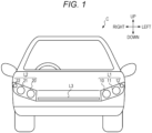
Fig. 1 is a view illustrating the outline of the front of a vehicle C; -
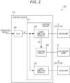
Fig. 2 is a diagram illustrating the outline of avehicle lamp 100; -
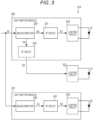
Fig. 3 is a diagram illustrating one example of the configuration of alighting device 210; -
Fig. 4 is a diagram illustrating one example of part of amicrocomputer 230 andIF circuits -
Fig. 5 is a chart for describing a signal S1; -
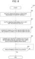
Fig. 6 is a flowchart illustrating one example of processing executed by acontrol device 110; and -
Fig. 7 is a graph for describing one example of a change in signals S1 to S3. - At least the following matters will be apparent from description of the present specification and illustration of the accompanying drawings.
-
Fig. 1 is a view illustrating the outline of the front of a vehicle C. Note that inFig. 1 , the vertical direction in the plane of paper will be defined as an up-down direction and the horizontal direction in the plane of paper will be defined as a left-right direction. In addition, the upper side in the plane of paper will be defined as "up" in the up-down direction and the right side in the plane of paper will be defined as "left" in the left-right direction. Further, the near side in the plane of paper will be referred to as "front" in a front-rear direction. Here, headlamps L1, L2 and an accessory lamp L3 are provided at the front of the vehicle C. - The headlamp L1 is a lamp attached to the front left of the vehicle C, and includes a
low beam lamp 10, ahigh beam lamp 11, and a lamp 12 (i.e., clearance lamp) for indicating the width of the vehicle C. - The headlamp L2 is a lamp attached to the front right of the vehicle C, and includes a
low beam lamp 20, ahigh beam lamp 21, and a lamp 22 (i.e., clearance lamp) for indicating the width of the vehicle C. Note that thelamps lamps lamp 22 is similar to thelamp 12. - The accessory lamp L3 is a lamp attached to the front center of the vehicle C to indicate the width of the vehicle C together with the
lamps -
Fig. 2 is a diagram illustrating one example of the configuration of avehicle lamp 100 provided in the vehicle C. Thevehicle lamp 100 includes the headlamps L1, L2, the accessory lamp L3, and acontrol device 110. - The
control device 110 is a device that controls lighting of the headlamps L1, L2 and the accessory lamp L3, and includes an electronic control unit (ECU) 200 and alighting device 210. - The
ECU 200 outputs an instruction signal SI corresponding to a user's operation result to thelighting device 210. Here, the "operation" is an operation for turning on at least one of the headlamps L1, L2 and the accessory lamp L3. The "operation" is not limited to an operation of a user operating part of the vehicle C (for example, an indicator for turning on or off the headlamp), and includes, for example, a keyless operation of the vehicle C and an operation of bringing a smart key close to the vehicle C. - Note that the "keyless" is, for example, a device capable of remotely unlocking and locking the door of the vehicle C. In addition, the "smart key" is, for example, a device that instructs the vehicle C to unlock the door of the vehicle C when the smart key is within a predetermined area from the vehicle C. Note that hereinafter, devices such as the keyless and the smart key may be simply referred to as "keyless etc."
- The
lighting device 210 is a device that turns on or off the headlamps L1, L2 and the accessory lamp L3 based on the instruction signal SI, and includeslight emitting modules lighting circuit 222. - The
light emitting module 220 turns on or off the headlamp L1 based on the instruction signal SI, and thelight emitting module 221 turns on or off the headlamp L2 based on the instruction signal SI. For example, when the ECU 200 outputs the instruction signal SI for turning on thelow beam lamps light emitting module 220 turns on thelamp 10, and thelight emitting module 221 turns on thelamp 20. - When the
ECU 200 outputs the instruction signal SI for turning off thelamps lamps light emitting module 220 turns off thelamp 10, and thelight emitting module 221 turns off thelamp 20. - Although details will be described later, the
light emitting module 220 outputs, to thelighting circuit 222, a signal S2 (described later) for turning on the accessory lamp L3 based on the instruction signal S1 for turning on the accessory lamp L3. - The
lighting circuit 222 turns on the accessory lamp L3 based on the signal S2. Note that "lighting/turning on" includes not only a case where the brightness of the lamp is immediately changed to a predetermined brightness, but also a case where the brightness of the lamp is gradually changed, for example. Further, a gradual increase in the brightness of the lamp (i.e., the light amount of the lamp is gradually increased) will be referred to as "gradual lighting/turning on." - Incidentally, the
lighting device 210 of the present embodiment gradually turns on theclearance lamps lamps lighting device 210 will be mainly described below. -
Fig. 3 is a diagram illustrating one example of the configurations of thelight emitting modules lamps lamps lamps light emitting modules - Each of the
lamps lamps - The
light emitting module 220 turns on thelamp 12 based on the instruction signal SI, and outputs the signal S2 (described later) for turning on the accessory lamp L3 to thelighting circuit 222. Thelight emitting module 220 includes amicrocomputer 230, interface (IF)circuits lighting circuit 233. -
Fig. 4 is a diagram illustrating one example of a partial configuration of themicrocomputer 230 and the configuration of theIF circuits microcomputer 230 generates signals Sa, Sb, which are pulse width modulation (PWM) signals, based on the instruction signal SI for gradually turning on the three lamps. - The
microcomputer 230 includes acontrol unit 300 andtransistors 310, 311. Thecontrol unit 300 is a functional block implemented by themicrocomputer 230 when an arithmetic circuit (not illustrated) of themicrocomputer 230 executes a program stored in a memory (not illustrated). Thecontrol unit 300 controls ON and OFF of thetransistors 310, 311 based on the instruction signal SI. - The
transistor 310 is an MOS transistor forming a so-called open drain circuit, and a drain terminal of thetransistor 310 is connected to aterminal 320 of themicrocomputer 230. The transistor 311 is also an MOS transistor forming an open drain circuit as in thetransistor 310. A drain terminal of the transistor 311 is connected to aterminal 321 of themicrocomputer 230. - The
IF circuit 231 is a circuit that outputs the signal S1 having the same logic level as the logic level of the signal Sa to thelighting circuit 233, and includes aresistor 500 and abuffer 501. A power supply voltage Vdd is applied to one end of theresistor 500, and the other end is connected to the terminal 320. Thus, theresistor 500 functions as a so-called pull-up resistor. - Thus, in the present embodiment, when the
control unit 300 turns on thetransistor 310, the signal Sa generated in the terminal 320 changes to a low level (hereinafter, L-level), and when thecontrol unit 300 turns off the transistor M1, the signal Sa changes to a high level (hereinafter, H-level). - The
buffer 501 outputs, to thelighting circuit 233, the signal S1 having the same logic level as that of the input signal Sa. Specifically, thebuffer 501 outputs the H-level signal S1 when the H-level signal Sa is input thereto, and outputs the L-level signal S1 when the L-level signal Sa is input thereto. -
Fig. 5 is a chart for describing one example of the signal S1. Thecontrol unit 300 of the present embodiment turns on and off thetransistor 310 to generate the pulse-width modulated signal Sa, S1. Here, the cycle of the signal S1, which is the PWM signal, is T0, and a period in which the signal S1 is at the H-level in each cycle T0 is T1, and a period in which the signal S1 is at the L-level in each cycle T0 is T2. In this case, a "duty ratio D (so-called on-duty ratio)" is expressed by Equation (1) below:
- The
IF circuit 232 is a circuit that outputs the signal S2 having the same logic level as the logic level of the signal Sb to thelighting circuit 222, and includes aresistor 510 and abuffer 511. Theresistor 510 and buffer 511 of theIF circuit 232 are similar to theresistor 500 and buffer 501 of theIF circuit 231, and for this reason, here, detailed description thereof will be omitted. - The
lighting circuit 233 performs PWM lighting (i.e., gradual lighting) of thelamp 12 in synchronization with the input signal S1. Specifically, thelighting circuit 233 supplies thelamp 12 with current which increases as the duty ratio D of the signal S1 increases. - Incidentally, the
lighting circuit 233 has a dead band in which the current cannot be supplied to thelamp 12 when the duty ratio D of the signal S1 is less than a predetermined value Da (for example, 3%). That is, when the duty ratio D of the signal S1 input to thelighting circuit 233 is less than the predetermined value Da, thelighting circuit 233 cannot turn on thelamp 12. - On the other hand, when the duty ratio D of the signal S1 reaches the predetermined value Da or more, the
lighting circuit 233 can supply the current to thelamp 12 to turn on thelamp 12. Then, thelighting circuit 233 increases the brightness of thelamp 12 according to the increase in the duty ratio D. Although details will be described later, in the present embodiment, themicrocomputer 230 needs to change the duty ratio D of the signal Sa not from 0% but from the predetermined value Da (for example, 3%) when turning on thelamp 12. - Note that in the present embodiment, the
lamp 12 is equivalent to a "first light source," the signal S1 is equivalent to a "first signal (or a first PWM signal)," and thelighting circuit 233 is equivalent to a "first lighting circuit." In addition, the duty ratio D of the signal S1 is equivalent to a "first duty ratio," and the duty ratio D of the signal S1 reaching the predetermined value Da or more is equivalent to "the state of the first signal satisfying a first condition for turning on the lamp 12 (first light source)." - The
light emitting module 221 ofFig. 3 is a module that turns on thelamp 22 based on the instruction signal SI as in thelight emitting module 220, and includes amicrocomputer 240, an IFcircuit 241, and alighting circuit 242. Here, although not illustrated, themicrocomputer 240 includes thecontrol unit 300 and thetransistor 310 in themicrocomputer 230 ofFig. 4 . TheIF circuit 241 is similar to theIF circuit 231, and thelighting circuit 242 is similar to thelighting circuit 233. - Thus, here, although detailed description of the
light emitting module 221 will be omitted, a signal Sc generated by themicrocomputer 240 and a signal S3 from theIF circuit 241 are PWM signals similar to the signals Sa, S1. Note that thelighting circuit 242 also has a dead band in which thelamp 22 cannot be turned on when the duty ratio D of the signal S3 is less than a predetermined value Da (for example, 3%), as in thelighting circuit 233. - Thus, when the duty ratio D of the signal S3 reaches the predetermined value Da or more, the
lighting circuit 242 can turn on thelamp 22 and increase the brightness of thelamp 22 according to the increase in the duty ratio D. - Note that here, the
lamp 22 is equivalent to a "third light source," the signal S3 is equivalent to a "third signal," and thelighting circuit 242 is equivalent to a "third lighting circuit." In addition, the duty ratio D of the signal S3 reaching the predetermined value Da or more is equivalent to "the state of the third signal satisfying a third condition for turning on the lamp 22 (third light source)." - The
lighting circuit 222 shown inFig. 3 performs PWM lighting of the accessory lamp L3 in synchronization with the input signal S2. Specifically, thelighting circuit 222 supplies the accessory lamp L3 with current which increases as the duty ratio D of the signal S2 increases. Thus, the accessory lamp L3 is gradually turned on according to the increase in the duty ratio D. - Incidentally, the
lighting circuit 222 has a dead band in which the accessory lamp L3 cannot be turned on when the duty ratio D of the signal S2 is less than a predetermined value Db (for example, 4%). Thus, when the duty ratio D of the signal S2 reaches the predetermined value Db or more, thelighting circuit 222 can turn on the accessory lamp L3 and increase the brightness of the accessory lamp L3 according to the increase in the duty ratio D. - Note that in the present embodiment, the accessory lamp L2 is equivalent to a "second light source," the signal S2 is equivalent to a "second signal (or a second PWM signal)," and the
lighting circuit 222 is equivalent to a "second lighting circuit." In addition, the duty ratio D of the signal S2 is equivalent to a "second duty ratio," and the duty ratio D of the signal S2 reaching the predetermined value Db or more is equivalent to "the state of the second signal satisfying a second condition for turning on the accessory lamp L2 (second light source)." - Here, the condition (second condition) for turning on the accessory lamp L3 by the
lighting circuit 222 is different from the condition (first condition) for turning on thelamp 12 by thelighting circuit 233. This is because, for example, circuits and elements forming each of thelighting circuits - In the present embodiment, the
microcomputer 230 and theIF circuits microcomputer 240 and theIF circuit 241 are equivalent to a "second output circuit." - Note that in the
light emitting module 220 ofFig. 3 , themicrocomputer 230 and theIF circuits microcomputer 230 may include theIF circuits microcomputer 230 is equivalent to the "first output circuit." - The
microcomputer 240 may also include theIF circuit 241. In this case, themicrocomputer 240 is equivalent to the "second output circuit." -
Fig. 6 is a flowchart illustrating one example of processing S10 executed by thecontrol device 110 when the door of the vehicle C is unlocked.Fig. 7 is a graph illustrating one example of a change in the duty ratios of the signals S1 to S3 generated by thelight emitting modules - Hereinafter, in the present embodiment, the above-described predetermined value Da is 3%, and the predetermined value Db is 4%. Thus, when the signal S1, S3 having a duty ratio D of 3% or more is input to the
lighting circuit lighting circuit lamp lighting circuit 222 turns on the accessory lamp L3 when the signal S2 having a duty ratio D of 4% or more is input thereto. - First, for example, when a user operates the keyless etc. to unlock the door of the vehicle C at a time point t0 in
Fig. 7 , theECU 200 inFig. 2 receives an operation result indicating unlocking of the door (S20). TheECU 200 outputs, to thelight emitting modules lamps - As a result, the
microcomputer 230 of thelight emitting module 220 starts generating the signals Sa, Sb, and themicrocomputer 240 of thelight emitting module 221 starts generating the signal Sc (S22 and a time point t1 inFig. 7 ). Here, in the processing S22, themicrocomputer 230 sets an initial value D1 of the duty ratio D of the signal Sa to 4% (value of the predetermined value Da or more), and sets an initial value D2 of the duty ratio D of the signal Sb to 4% (value of the predetermined value Db or more). - The
microcomputer 240 also sets an initial value D3 of the duty ratio D of the signal Sc to 4% (value of the predetermined value Da or more). As described above, the duty ratios D of the signals S1 to S3 are equal to the duty ratios D of the signals Sa to Sc. Thus, when the signals Sa to Sc are generated at the time point t1, thelighting circuits lamps lighting circuit 222 turns on the accessory lamp L3. - With this configuration, in the present embodiment, the
lamps lamps - For example, the initial value D1 of the signal Sa may be set to 3%, the initial value D2 of the signal Sb may be set to 4%, and the initial value D3 of the signal Sc may be set to 5%, which are different from each other. Note that the initial value D1 is equivalent to a "first initial value (or a first initial state)," and the initial value D2 is equivalent to a "second initial value (or a second initial state)." Further, the initial value D3 is equivalent to a "third initial state."
- Thereafter, the
microcomputers lamps - Specifically, the
microcomputer 230 increases the duty ratio D of the signal Sa to 30% and increases the duty ratio D of the signal Sb to 35% by the time point t2 (S23). As in the signal Sa of themicrocomputer 230, themicrocomputer 240 also increases the duty ratio D of the signal Sc to 30% by the time point t2. - As described above, the signals S1 to S3 change similarly to the respective signals Sa to Sc. As a result, the
lamps - Note that in the present embodiment, the
lamps lighting circuits lamps - On the other hand, the accessory lamp L3 is different from the
lamps lighting circuit 222 is also different from the configurations of thelighting circuits lamps - With this configuration, in the present embodiment, the brightness of each of the
lamps - The
microcomputers microcomputers - At the time point t3, the
microcomputers lamps lighting circuits lighting circuit 222 different from each other in an operating condition are used, it is possible to gradually turn on the lamps to the predetermined brightness A0 while suppressing the deviation in the lighting timing between the three lamps. - Note that in the processing S24, the
microcomputers microcomputers ECU 200. As a result, the three lamps may be turned off before the time point t3. - In the present embodiment, the lighting circuit such as the
lighting circuit 222 turns on the lamp when the duty ratio of the input PWM signal reaches the predetermined value, and brightens the lamp according to the increase in the duty ratio, but the present invention is not limited thereto. - For example, the lighting circuit may be a circuit that turns on a lamp when the level of input DC voltage reaches a predetermined value and brightens the lamp according to the increase in the level. Here, the lighting circuits X1 for turning on the
lamps - For example, the lighting circuit X1 turns on the
lamp 12 when the DC voltage level reaches 0.6 V, and sets thelamp 12 to the predetermined brightness A0 when the DC voltage level reaches 3.0 V The lighting circuit X2 turns on the accessory lamp L3 when the DC voltage level reaches 0.8 V, and sets the accessory lamp L3 to the predetermined brightness A0 when the DC voltage level reaches 3.5 V - In such a case, for example, if the
microcomputer 230 outputs the DC voltage changing from 0.6 V to 3.0 V to the lighting circuit X1 and outputs the DC voltage changing from 0.8 V to 3.5 V to the lighting circuit X2 in the period Ta based on the instruction signal SI, effects similar to those of the present embodiment can be obtained. - For example, the
lighting circuit 233 may be a circuit capable of setting a current value (i.e., current value to thelamp 12 when the duty ratio D of the signal S1 is 30%), which can be supplied to thelamp 12 by thelighting circuit 233, based on the duty ratio of the PWM signal different from that of the signal S1. - Note that even if the
lighting circuit 233 is such a circuit, it is necessary to input the signal S1 having a duty ratio D of the predetermined value Da or more to thelighting circuit 233 in order to turn on thelamp 12. - The
vehicle lamp 100 of the present embodiment has been described above. For example, thelighting circuit 233 andlighting circuit 222 of thelighting device 210 ofFig. 3 are different from each other in an operating condition for turning on the lamp. However, when turning on thelamp 12 and the accessory lamp L3, themicrocomputer 230 of the present embodiment generates the signals Sa, Sb enabling both the twolighting circuits lamp 12 and the accessory lamp L3. - The
lighting circuit 233 performs PWM lighting of the accessory lamp L3, and thelighting circuit 222 performs PWM lighting of thelamp 12. Note that thelighting circuits - The
lighting circuit 233 can gradually turn on the accessory lamp L3 according to the duty ratio of the signal S1, and thelighting circuit 222 can gradually turn on thelamp 12 according to the duty ratio of the signal S2. - The
microcomputer 230 also generates the signals Sa, Sb such that the brightnesses of thelamp 12 and the accessory lamp L3 reach the predetermined brightness A1 in the predetermined period Ta (seeFig. 7 ) after thelamp 12 and the accessory lamp L3 have been turned on. As a result, in the present embodiment, the change in brightness of thelamp 12 can be made substantially equal to the change in brightness of the accessory lamp L3. Thus, even in the period in which the brightness of each of thelamp 12 and the accessory lamp L3 changes, it is possible to suppress deviation in brightness between thelamp 12 and the accessory lamp L3. - The
lighting device 210 is provided with thelight emitting module 221 that turns on thelamp 22. Thus, in the present embodiment, it is possible to suppress the deviation in the timing of turning on thelamps - As illustrated in
Fig. 1 , the accessory lamp L3 is disposed between theleft lamp 12 and theright lamp 22 at the front of the vehicle C. In the present embodiment, it is possible to suppress deviation between the timing of turning on the accessory lamp L3 adjacent to thelamps lamps - The
microcomputer 230 gradually turns on thelamp 12 and the accessory lamp L3, for example, when the keyless etc. are operated to unlock the door of the vehicle C. Thus, the user of the vehicle C can safely access the vehicle C particularly during night. - The above-described embodiments are for the sake of easy understanding of the present invention, and are not intended to limit the present invention. In addition, the present invention can be changed or modified without departing from the gist thereof, and the present invention includes equivalents thereof, needless to say.
- The present international application claims priority based on
Japanese Patent Application No.2022-080878 filed on May 17, 2022 Japanese Patent Application No. 2022-080878 - The description of the specific embodiments of the present invention is presented for the purpose of illustration. The specific embodiments are not intended to be exhaustive or to limit the invention as it is in the form described. It is obvious to those skilled in the art that many modifications and alterations are possible in light of the contents of the description above.
-
- 10 to 12, 20 to 22
- Lamp
- 100
- Vehicle lamp
- 110
- Control device
- 200
- ECU
- 210
- Lighting device
- 220, 221
- Light emitting module
- 222, 233, 242
- Lighting circuit
- 230, 240
- Microcomputer
- 231, 232, 241
- IF circuit
- 300
- Control unit
- 310, 311
- Transistor
- 320, 321
- Terminal
- 500, 510
- Resistor
- Buffer
- 501, 511
- C
- Vehicle
- L1, L2
- Headlamp
- L3
- Accessory lamp
Claims (7)
- A lighting device comprising:a first lighting circuit that turns on a first light source when a state of a first signal satisfies a first condition and changes a brightness of the first light source according to the state of the first signal;a second lighting circuit that turns on a second light source when a state of a second signal satisfies a second condition different from the first condition and changes a brightness of the second light source according to the state of the second signal; anda first output circuit that outputs, to the first lighting circuit, the first signal whose state changes from a first initial state satisfying the first condition such that the first light source is turned on and is gradually brightened, and outputs, to the second lighting circuit, the second signal whose state changes from a second initial state satisfying the second condition such that the second light source is turned on and is gradually brightened, based on an instruction signal.
- The lighting device according to claim 1, whereinthe first lighting circuit performs PWM lighting of the first light source, andthe second lighting circuit performs PWM lighting of the second light source.
- The lighting device according to claim 2, whereinthe first output circuitoutputs, as the first signal, a first PWM signal whose first duty ratio changes from a first initial value satisfying the first condition, and outputs, as the second signal, a second PWM signal whose second duty ratio changes from a second initial value satisfying the second condition, based on the instruction signal,the first lighting circuitperforms the PWM lighting of the first light source in synchronization with the first PWM signal, and changes the brightness of the first light source according to the first duty ratio of the first PWM signal, andthe second lighting circuitperforms the PWM lighting of the second light source in synchronization with the second PWM signal, and changes the brightness of the second light source according to the second duty ratio of the second PWM signal.
- The lighting device according to claim 3, whereinthe first output circuitchanges the first duty ratio and the second duty ratio such that the brightness of each of the first light source and the second light source reaches a predetermined brightness in a predetermined period after each of the first light source and the second light source has been turned on.
- The lighting device according to any one of claims 1 to 4, further comprising:a third lighting circuit that turns on a third light source when a state of a third signal satisfies a third condition and changes a brightness of the third light source according to the state of the third signal; anda second output circuit that outputs, to the third lighting circuit, the third signal whose state changes from a third initial state satisfying the third condition such that the third light source is turned on and is gradually brightened based on the instruction signal.
- A vehicle lamp comprising:the lighting device according to claim 5; andthe first to third light sources arranged at a front of the vehicle,wherein the second light source is disposed between the first light source and the third light source.
- A lighting device for turning on a first light source and a second light source attached to a vehicle, comprising:a first lighting circuit that turns on the first light source when a state of a first signal satisfies a first condition and changes a brightness of the first light source according to the state of the first signal;a second lighting circuit that turns on the second light source when a state of a second signal satisfies a second condition different from the first condition and changes a brightness of the second light source according to the state of the second signal; anda first output circuit that outputs, to the first lighting circuit, the first signal whose state changes from a first initial state satisfying the first condition such that the first light source is turned on and is gradually brightened, and outputs, to the second lighting circuit, the second signal whose state changes from a second initial state satisfying the second condition such that the second light source is turned on and is gradually brightened, when a door of the vehicle is unlocked.
Applications Claiming Priority (2)
| Application Number | Priority Date | Filing Date | Title |
|---|---|---|---|
| JP2022080878A JP7773432B2 (en) | 2022-05-17 | 2022-05-17 | Lighting device, vehicle lighting fixture |
| PCT/JP2023/017120 WO2023223835A1 (en) | 2022-05-17 | 2023-05-02 | Lighting device and vehicle lamp |
Publications (2)
| Publication Number | Publication Date |
|---|---|
| EP4529359A1 true EP4529359A1 (en) | 2025-03-26 |
| EP4529359A4 EP4529359A4 (en) | 2025-05-14 |
Family
ID=88835149
Family Applications (1)
| Application Number | Title | Priority Date | Filing Date |
|---|---|---|---|
| EP23807442.1A Withdrawn EP4529359A4 (en) | 2022-05-17 | 2023-05-02 | VEHICLE LIGHTING DEVICE AND LAMP |
Country Status (4)
| Country | Link |
|---|---|
| EP (1) | EP4529359A4 (en) |
| JP (1) | JP7773432B2 (en) |
| CN (1) | CN119547567A (en) |
| WO (1) | WO2023223835A1 (en) |
Family Cites Families (11)
| Publication number | Priority date | Publication date | Assignee | Title |
|---|---|---|---|---|
| JPH05109490A (en) * | 1991-10-14 | 1993-04-30 | Fujitsu Ten Ltd | Panel illumination control device for on-vehicle apparatus |
| JP3873541B2 (en) * | 1999-09-27 | 2007-01-24 | 松下電工株式会社 | Dimmable lighting device |
| JP6295513B2 (en) * | 2013-03-11 | 2018-03-20 | コニカミノルタ株式会社 | Image reading apparatus and image forming apparatus |
| JP6307949B2 (en) * | 2014-03-12 | 2018-04-11 | 株式会社デンソー | Vehicle control system |
| JP2015171850A (en) * | 2014-03-12 | 2015-10-01 | 住友ゴム工業株式会社 | Pneumatic tire |
| WO2015170403A1 (en) | 2014-05-09 | 2015-11-12 | 市光工業株式会社 | Vehicular head lamp device |
| JP6697729B2 (en) | 2015-07-09 | 2020-05-27 | パナソニックIpマネジメント株式会社 | Lighting device, lighting device, and vehicle using the same |
| CN105578650B (en) * | 2016-01-13 | 2017-10-20 | 矽恩微电子(厦门)有限公司 | A kind of automobile reading lamp LED drive chip |
| JP2020055425A (en) | 2018-10-02 | 2020-04-09 | 市光工業株式会社 | Illumination device |
| JP7082586B2 (en) * | 2019-03-18 | 2022-06-08 | 本田技研工業株式会社 | Lighting control device and lighting control method |
| DE102020130402B4 (en) | 2020-11-18 | 2025-01-02 | Dr. Ing. H.C. F. Porsche Aktiengesellschaft | Flexible conductor element with length compensation section |
-
2022
- 2022-05-17 JP JP2022080878A patent/JP7773432B2/en active Active
-
2023
- 2023-05-02 EP EP23807442.1A patent/EP4529359A4/en not_active Withdrawn
- 2023-05-02 CN CN202380036369.5A patent/CN119547567A/en active Pending
- 2023-05-02 WO PCT/JP2023/017120 patent/WO2023223835A1/en not_active Ceased
Also Published As
| Publication number | Publication date |
|---|---|
| EP4529359A4 (en) | 2025-05-14 |
| CN119547567A (en) | 2025-02-28 |
| WO2023223835A1 (en) | 2023-11-23 |
| JP7773432B2 (en) | 2025-11-19 |
| JP2023169640A (en) | 2023-11-30 |
Similar Documents
| Publication | Publication Date | Title |
|---|---|---|
| US7323831B2 (en) | Illumination device | |
| EP3247173B1 (en) | Integrated circuit for driving a light emitting element | |
| US7064553B2 (en) | Open-circuit detecting circuit | |
| EP3785992A1 (en) | Rear turn lamp | |
| EP3202620B1 (en) | Light emitting element drive device, light emitting device, and vehicle | |
| US6958584B2 (en) | Lamp driving apparatus and method for driving lamp | |
| US9130546B2 (en) | Drive circuit for semiconductor device | |
| US10143055B2 (en) | Illuminating device for vehicles | |
| CA2504549C (en) | Illumination control apparatus and failure detecting apparatus | |
| US8098018B2 (en) | Pulse dimming circuit and the method thereof | |
| US6369513B1 (en) | Vehicle lamp lighting-driving apparatus | |
| US20170197545A1 (en) | Led driver chip for car reading light and state control method thereof | |
| WO2021106344A1 (en) | Light emission control system, light emission system, light emission control device, and light emission device | |
| US11865968B2 (en) | Vehicle lamp and lamp control module | |
| JP7773432B2 (en) | Lighting device, vehicle lighting fixture | |
| US6911790B2 (en) | Multiplexed high voltage DC-AC driver | |
| US20250042330A1 (en) | Lighting circuit | |
| WO2022133671A1 (en) | Light assembly for performing lighting functions with switching units in low side position | |
| WO2023106199A1 (en) | Lighting circuit and vehicle lamp | |
| US8154208B2 (en) | Method of supplying power to an automobile headlight lamp and headlight using that method | |
| US20100084978A1 (en) | System And Method For Driving LED Vehicle Lights | |
| US12058793B2 (en) | Display device, display system, and method of controlling display device | |
| CN121970493A (en) | Lighting circuit and vehicle lamp | |
| WO2025263263A1 (en) | Lighting circuit and vehicle lamp | |
| WO2025094580A1 (en) | Control device, vehicle lamp, and program |
Legal Events
| Date | Code | Title | Description |
|---|---|---|---|
| STAA | Information on the status of an ep patent application or granted ep patent |
Free format text: STATUS: THE INTERNATIONAL PUBLICATION HAS BEEN MADE |
|
| PUAI | Public reference made under article 153(3) epc to a published international application that has entered the european phase |
Free format text: ORIGINAL CODE: 0009012 |
|
| STAA | Information on the status of an ep patent application or granted ep patent |
Free format text: STATUS: REQUEST FOR EXAMINATION WAS MADE |
|
| 17P | Request for examination filed |
Effective date: 20241108 |
|
| AK | Designated contracting states |
Kind code of ref document: A1 Designated state(s): AL AT BE BG CH CY CZ DE DK EE ES FI FR GB GR HR HU IE IS IT LI LT LU LV MC ME MK MT NL NO PL PT RO RS SE SI SK SM TR |
|
| A4 | Supplementary search report drawn up and despatched |
Effective date: 20250414 |
|
| RIC1 | Information provided on ipc code assigned before grant |
Ipc: H05B 45/46 20200101ALI20250408BHEP Ipc: H05B 47/105 20200101ALI20250408BHEP Ipc: H05B 45/325 20200101ALI20250408BHEP Ipc: H05B 45/10 20200101ALI20250408BHEP Ipc: B60Q 1/50 20060101ALI20250408BHEP Ipc: B60Q 1/28 20060101ALI20250408BHEP Ipc: H05B 47/165 20200101AFI20250408BHEP |
|
| STAA | Information on the status of an ep patent application or granted ep patent |
Free format text: STATUS: THE APPLICATION HAS BEEN WITHDRAWN |
|
| 18W | Application withdrawn |
Effective date: 20250513 |