EP4529344A1 - Pdu-sitzungsmodifizierungsverfahren für industriellen verkehr - Google Patents
Pdu-sitzungsmodifizierungsverfahren für industriellen verkehr Download PDFInfo
- Publication number
- EP4529344A1 EP4529344A1 EP23835734.7A EP23835734A EP4529344A1 EP 4529344 A1 EP4529344 A1 EP 4529344A1 EP 23835734 A EP23835734 A EP 23835734A EP 4529344 A1 EP4529344 A1 EP 4529344A1
- Authority
- EP
- European Patent Office
- Prior art keywords
- pdu session
- session modification
- message
- network
- traffic
- Prior art date
- Legal status (The legal status is an assumption and is not a legal conclusion. Google has not performed a legal analysis and makes no representation as to the accuracy of the status listed.)
- Pending
Links
Images


Classifications
-
- H—ELECTRICITY
- H04—ELECTRIC COMMUNICATION TECHNIQUE
- H04W—WIRELESS COMMUNICATION NETWORKS
- H04W76/00—Connection management
- H04W76/10—Connection setup
- H04W76/18—Management of setup rejection or failure
-
- H—ELECTRICITY
- H04—ELECTRIC COMMUNICATION TECHNIQUE
- H04L—TRANSMISSION OF DIGITAL INFORMATION, e.g. TELEGRAPHIC COMMUNICATION
- H04L67/00—Network arrangements or protocols for supporting network services or applications
- H04L67/14—Session management
- H04L67/142—Managing session states for stateless protocols; Signalling session states; State transitions; Keeping-state mechanisms
-
- H—ELECTRICITY
- H04—ELECTRIC COMMUNICATION TECHNIQUE
- H04L—TRANSMISSION OF DIGITAL INFORMATION, e.g. TELEGRAPHIC COMMUNICATION
- H04L67/00—Network arrangements or protocols for supporting network services or applications
- H04L67/01—Protocols
- H04L67/12—Protocols specially adapted for proprietary or special-purpose networking environments, e.g. medical networks, sensor networks, networks in vehicles or remote metering networks
-
- H—ELECTRICITY
- H04—ELECTRIC COMMUNICATION TECHNIQUE
- H04L—TRANSMISSION OF DIGITAL INFORMATION, e.g. TELEGRAPHIC COMMUNICATION
- H04L67/00—Network arrangements or protocols for supporting network services or applications
- H04L67/14—Session management
-
- H—ELECTRICITY
- H04—ELECTRIC COMMUNICATION TECHNIQUE
- H04W—WIRELESS COMMUNICATION NETWORKS
- H04W4/00—Services specially adapted for wireless communication networks; Facilities therefor
- H04W4/70—Services for machine-to-machine communication [M2M] or machine type communication [MTC]
-
- H—ELECTRICITY
- H04—ELECTRIC COMMUNICATION TECHNIQUE
- H04W—WIRELESS COMMUNICATION NETWORKS
- H04W76/00—Connection management
- H04W76/20—Manipulation of established connections
-
- H—ELECTRICITY
- H04—ELECTRIC COMMUNICATION TECHNIQUE
- H04B—TRANSMISSION
- H04B7/00—Radio transmission systems, i.e. using radiation field
- H04B7/14—Relay systems
- H04B7/15—Active relay systems
- H04B7/185—Space-based or airborne stations; Stations for satellite systems
- H04B7/18502—Airborne stations
- H04B7/18504—Aircraft used as relay or high altitude atmospheric platform
-
- H—ELECTRICITY
- H04—ELECTRIC COMMUNICATION TECHNIQUE
- H04W—WIRELESS COMMUNICATION NETWORKS
- H04W56/00—Synchronisation arrangements
- H04W56/001—Synchronization between nodes
- H04W56/0015—Synchronization between nodes one node acting as a reference for the others
-
- H—ELECTRICITY
- H04—ELECTRIC COMMUNICATION TECHNIQUE
- H04W—WIRELESS COMMUNICATION NETWORKS
- H04W60/00—Affiliation to network, e.g. registration; Terminating affiliation with the network, e.g. de-registration
-
- H—ELECTRICITY
- H04—ELECTRIC COMMUNICATION TECHNIQUE
- H04W—WIRELESS COMMUNICATION NETWORKS
- H04W8/00—Network data management
- H04W8/22—Processing or transfer of terminal data, e.g. status or physical capabilities
- H04W8/24—Transfer of terminal data
Definitions
- the present disclosure relates to a mobile communication.
- LTE long term evolution
- LTE-A LTE-Advanced
- 5th generation also known as 5G
- the 5G mobile communication defined in the international telecommunication union (ITU) provides a data transfer rate of up to 20Gbps and a sensible transfer rate of at least 100Mbps anytime anywhere.
- 'IMT-2020' is a formal name, and aims to be commercialized in the year 2020 worldwide.
- the 5G mobile communication supports a plurality of numerologies or subcarrier spacing (SCS) for supporting various services. For example, when the SCS is 15 kHz, a wide area over conventional cellular bands is supported; in the case of 30 kHz/60 kHz, a dense urban area, lower latency, and wider carrier bandwidth is supported; and when the SCS is larger than 60 kHz or higher, bandwidth larger than 24.25 GHz is supported to overcome phase noise.
- SCS subcarrier spacing
- the NR frequency band is defined by two types (FR1, FR2) of frequency ranges.
- the FR1 ranges from 410 MHz to 7125 MHz
- the FR2 ranges from 24250 MHz to 52600 MHz, which may correspond to the millimeter wave (mmW) range.
- mmW millimeter wave
- the FR1 may indicate the "sub-6GHz range” while the FR2 may indicate the “above 6GHz range” and may be referred to as the millimeter wave (mmW).
- Table 1 Frequency Range designation Corresponding frequency range Subcarrier Spacing FR1 450MHz - 6000MHz 15, 30, 60kHz FR2 24250MHz - 52600MHz 60, 120, 240kHz
- the FR1 may include a frequency band ranging from 410 MHz to 7125 MHz as shown in Table 2.
- the FR1 may include a frequency band higher than 6 GHz (or 5850, 5900, or 5925 MHz).
- a frequency band higher than 6 GHz (or 5850, 5900, or 5925 MHz) included in the FR1 may include the unlicensed band.
- the unlicensed band may be utilized for various applications, which may include communication for vehicles (for example, autonomous driving).
- [Table 2] Frequency Range designation Corresponding frequency range Subcarrier Spacing FR1 410MHz - 7125MHz 15, 30, 60kHz FR2 24250MHz - 52600MHz 60, 120, 240kHz
- the ITU proposes three usage scenarios, e.g., eMBB(enhanced Mobile BroadBand), mMTC(massive Machine Type Communication), and URLLC(Ultra Reliable and Low Latency Communications).
- eMBB enhanced Mobile BroadBand
- mMTC massive Machine Type Communication
- URLLC Ultra Reliable and Low Latency Communications
- the URLLC relates to a usage scenario which requires a high reliability and a low latency.
- a service such as autonomous driving, factory automation, and augmented reality requires a high reliability and a low latency (e.g., a latency less than or equal to 1ms).
- a latency of 4G (LTE) is statistically 21-43ms (best 10%), 33-75ms (median). This is insufficient to support a service requiring the latency less than or equal to 1ms.
- an eMBB usage scenario relates to a usage scenario requiring a mobile ultra-wide band.
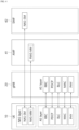
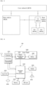
- FIG. 1 illustrates a structure of the next-generation mobile communication network.
- the 5G Core may include various constituting elements, and FIG. 1 shows Access and Mobility Management Function (AMF) 41, Session Management Function (SMF) 42, Policy Control Function (PCF) 43, User Plane Function (UPF) 44, Application Function (AF) 45, Unified Data Management (UDM) 46, and Non-3GPP InterWorking Function (N3IWF) 49, which correspond to part of the constituting elements.
- AMF Access and Mobility Management Function
- SMF Session Management Function
- PCF Policy Control Function
- UPF User Plane Function
- AF Application Function
- UDM Unified Data Management
- N3IWF Non-3GPP InterWorking Function
- the UE 10 is connected to the data network via the UPF 44 through the Next Generation Radio Access Network (NG-RAN).
- NG-RAN Next Generation Radio Access Network
- the UE 10 may receive a data service even through untrusted non-3rd Generation Partnership Project (3GPP) access, for example, Wireless Local Area Network (WLAN).
- 3GPP non-3rd Generation Partnership Project
- WLAN Wireless Local Area Network
- the N3IWF 49 may be deployed.
- FIG. 2 shows an example of an expected structure of next-generation mobile communication from a node perspective.
- a UE is coupled to a data network (DN) via a next generation radio access network (RAN).
- DN data network
- RAN next generation radio access network
- the illustrated control plane function (CPF) node performs the entirety or part of a mobility management entity (MME) function of 4G mobile communication and the entirety or part of a control plane function of an S-serving gateway (SG) and PDN gateway (P-GW).
- MME mobility management entity
- SG S-serving gateway
- P-GW PDN gateway
- the CPF node includes an access and mobility management function (AMF) and a session management function (SMF).
- AMF access and mobility management function
- SMF session management function
- the illustrated user plane function (UPF) node is a type of a gateway through which user data is transmitted/received.
- the UPF node may perform the entirety or part of a user plane function of an S-GW or P-GW of 4G mobile communication.
- PCF policy control function
- the illustrated application function is a server for providing several services to the UE.
- the illustrated unified data management is a type of a server which manages subscriber information, such as a home subscriber server (HSS) of 4G mobile communication.
- the UDM stores the subscriber information in a unified data repository (UDR) and manages it.
- UDR unified data repository
- the illustrated authentication server function (AUSF) authenticates and manages the UE.
- the illustrated network slice selection function (NSSF) is a node for network slicing as described below.
- the UE can simultaneously access two data networks by using multiple protocol data unit or packet data unit (PDU) sessions.
- PDU packet data unit
- FIG. 3 shows an example of an architecture for supporting simultaneous access to two data networks.
- a UE uses one PDU session to simultaneously access the two data networks.
- FIG. 4 illustrates another example of a structure of a radio interface protocol between a UE and a gNB.
- the radio interface protocol is based on the 3GPP radio access network specification.
- the radio interface protocol horizontally includes a physical layer, a data link layer, and a network layer; and is divided vertically into a user plane for data information transfer and a control plane for signaling transfer.
- the protocol layers may be divided into a first layer (L1), a second layer (L2), and a third layer (L3) based upon the lower three layers of the Open System Interconnection (OSI) reference model widely used for communication systems.
- OSI Open System Interconnection
- the physical layer namely the first layer, provides an information transfer service by using a physical channel.
- the physical layer is connected to a Medium Access Control (MAC) layer, namely, an upper layer of the physical layer, via a transport channel.
- MAC Medium Access Control
- Data is transferred between the MAC layer and the physical layer through the transport channel.
- data is transferred between different physical layers, namely, between physical layers of a transmitting side and a receiving side, through the physical channel.
- the second layer includes the MAC layer, a Radio Link Control (RLC) layer, and a Packet Data Convergence Protocol (PDCP) layer.
- RLC Radio Link Control
- PDCP Packet Data Convergence Protocol
- the third layer include a Radio Resource Control (hereinafter, simply referred to as RRC).
- RRC Radio Resource Control
- the RRC layer is defined only in the control plane and serves to control the logical channel, the transport channel, and the physical channel in association with configuration, re-configuration, and release of radio bearers (hereinafter, RBs for short).
- RB represents a service provided by the second layer for data transfer between the UE and the E-UTRAN.
- the Non-Access Stratum (NAS) layer performs a function such as connection management (session management) and mobility management.
- the NAS layer is divided into a NAS entity for Mobility Management (MM) and a NAS entity for Session Management (SM).
- MM Mobility Management
- SM Session Management
- an RRC layer, and RLC layer, a MAC layer, and a PHY layer located below the NAS layer are collectively called an access stratum (AS) layer.
- AS access stratum
- a network system for the next generation mobile communication (namely 5G) also supports non-3GPP access.
- Atypical example of the non-3GPP access is WLAN access.
- the WLAN access may include both trusted and untrusted WLANs.
- the AMF performs not only 3GPP access but also Registration Management (RM) and Connection Management (CM) for non-3GPP access.
- RM Registration Management
- CM Connection Management
- ultra reliable low latency communications networking technology for allowing people and things, online and offline, etc. to exchange and process information through organic connection therebetween has been emerging as an essential network infrastructure-based technology.
- TSN traffic time-sensitive networking
- TSN time-sensitive networking
- the present disclosure is intended to provide a method that may solve the aforementioned problem.
- the disclosure of this specification provides a method of operating in user equipment (UE).
- the method may include transmitting a Protocol Data Unit (PDU) Session Modification Request message; and receiving a PDU Session Modification Command message, a PDU Session Modification ACK message or a PDU Session Modification Reject message in response to the PDU Session Modification REQUEST message.
- the PDU Session Modification REQUEST message may include a PDU session type to indicate industrial traffic.
- the PDU Session Modification REJECT message may include a cause value indicating that a network does not support the PDU session type, upon receiving the PDU Session Modification REJECT message.
- the disclosure of this specification provides a chipset mounted to user equipment (UE).
- the chipset may include at least one processor; and at least one memory configured to store instructions and operably electrically connectable to the at least one processor.
- Operations performed based on the instructions executed by the at least one processor may include: transmitting a Protocol Data Unit (PDU) Session Modification Request message; and receiving a PDU Session Modification Command message, a PDU Session Modification ACK message or a PDU Session Modification Reject message in response to the PDU Session Modification REQUEST message.
- the PDU Session Modification REQUEST message may include a PDU session type to indicate industrial traffic.
- the PDU Session Modification REJECT message includes a cause value indicating that a network does not support the PDU session type, upon receiving the PDU Session Modification REJECT message.
- the apparatus may include a transceiver; at least one processor; and at least one memory configured to store instructions and operably electrically connectable to the at least one processor.
- Operations performed based on the instructions executed by the at least one processor may include: transmitting a Protocol Data Unit (PDU) Session Modification Request message; and receiving a PDU Session Modification Command message, a PDU Session Modification ACK message or a PDU Session Modification Reject message in response to the PDU Session Modification REQUEST message.
- the PDU Session Modification REQUEST message may include a PDU session type to indicate industrial traffic.
- the PDU Session Modification REJECT message includes a cause value indicating that a network does not support the PDU session type, upon receiving the PDU Session Modification REJECT message.
- the industrial traffic may include traffic for a Time Sensitive Network (TSN), Time-Sensitive Communication (TSC), Deterministic Networking (DetNet), Ultra Reliable and Low Latency Communications (URLLC) or Industrial Internet of Things (IIoT).
- TSN Time Sensitive Network
- TSC Time-Sensitive Communication
- DetNet Deterministic Networking
- URLLC Ultra Reliable and Low Latency Communications
- IIoT Industrial Internet of Things
- the PDU SESSION MODIFICATION REJECT message includes a back-off timer.
- the PDU SESSION MODIFICATION REJECT message includes a Re-attempt indicator.
- the Re-attempt indicator may indicate whether the UE is allowed to attempt a procedure related to a PDU session in an equivalent Public Land Mobile Network (PLMN) using the same the same data network name (DNN) and the same Single Network Slice Selection Assistance Information (S-NSSAI).
- PLMN Public Land Mobile Network
- DNN data network name
- S-NSSAI Single Network Slice Selection Assistance Information
- the PDU Session Modification Request message further includes capability information or indication related to the industrial traffic.
- the operations performed based on the execution by the method or the at least one processor may further include: transmitting a Registration Request message including capability information or the indication related to the industrial traffic.
- the operations performed based on the execution by the method or the at least one processor may further include: receiving a Registration Accept message including capability information or indication related to the industrial traffic.
- the operations performed based on the execution by the method or the at least one processor may further include: transmitting a UL Non-Access Stratum (NAS) TRANSPORT message including capability information or indication related to the industrial traffic.
- NAS Non-Access Stratum
- the operations performed based on the execution by the method or the at least one processor may further include: receiving a DL Non-Access Stratum (NAS) TRANSPORT message including capability information or indication related to the industrial traffic.
- NAS Non-Access Stratum
- the capability information or indication related to the industrial traffic may be configured in the UE or universal subscriber identity module (USIM) of the UE.
- USIM universal subscriber identity module
- the UE and the network can perform an efficient process by satisfying the service requirements for the industrial traffic (e.g., TSN traffic, TSC traffic, DetNet traffic, URLLC traffic, or IIoT traffic).
- TSN traffic, TSC traffic, DetNet traffic, URLLC traffic, or IIoT traffic unnecessary signaling overhead is reduced, thereby minimizing the battery and resource waste of the terminal and network.
- the term 'include' or 'have' may represent the existence of a feature, a number, a step, an operation, a component, a part or the combination thereof described in the specification, and may not exclude the existence or addition of another feature, another number, another step, another operation, another component, another part or the combination thereof.
- first' and 'second' are used for the purpose of explanation about various components, and the components are not limited to the terms 'first' and 'second'.
- the terms 'first' and 'second' are only used to distinguish one component from another component.
- a first component may be named as a second component without deviating from the scope of the present disclosure.
- a or B as used in the present disclosure may mean “only A”, “only B” or “both A and B”.
- a or B may be interpreted as “A and/or B” in the present disclosure.
- A, B or C may mean “only A”, “only B”, “only C” or "any combination of A, B and C”.
- the UE may extract and store allowed S-NSSAI and the mapped S-NSSAI, which are included in the registration accept message received from the network (namely, AMF) in the registration procedure of FIG. 5 . Therefore, the UE may transmit the PDU Session Establishment Request message by including both S-NSSAI based on the allowed NSSAI and the corresponding S-NSSAI based on the mapped NSSAI therein.
- the UE may generate a new PDU session ID.
- the AMF may determine default S-NSSAI on a PDU session requested according to UE subscription.
- the AMF may associate and store the PDU session ID with the SMF ID.
- the AMF may select SMF.
- the AMF may transmit an Nsmf_PDUSession_CreateSMContext request message or an Nsmf_PDUSession_UpdateSMContext request message to the selected SMF.
- the Nsmf_PDUSession_CreateSMContext request message is SUPI, DNN, S-NSSAI(s), PDU Session ID, AMF ID, Request Type, PCF ID, Priority Access, N1 SM container, User location information, Access Type, PEI, GPSI, UE presence in It may include LADN service area, Subscription For PDU Session Status Notification, DNN Selection Mode, and Trace Requirements.
- the SM container may include a PDU Session Establishment request message.
- the Nsmf_PDUSession_UpdateSMContext request message may include SUPI, DNN, S-NSSAI(s), SM Context ID, AMF ID, Request Type, N1 SM container, User location information, Access Type, RAT type, and PEI.
- the N1 SM container may include a PDU Session Establishment request message.
- the AMF ID is used to identify the AMF serving the UE.
- the N1 SM information may include a PDU session establishment request message received from the UE.
- SMF transmits a subscriber data request message to UDM.
- the subscriber data request message may include a subscriber permanent ID and DNN.
- UDM can transmit subscription data response message to SMF
- step 3 if the request type indicates "existing PDU session", the SMF determines that the request is due to handover between 3GPP access and non-3GPP access.
- the SMF can identify an existing PDU session based on the PDU session ID.
- the SMF may request subscription data.
- the subscription data may include information on an authenticated request type, an authenticated SSC mode, and a basic QoS profile.
- the SMF can check whether the UE request complies with the user subscription and local policy. Alternatively, the SMF rejects the UE request through NAS SM signaling (including the related SM rejection cause) delivered by the AMF, and the SMF informs the AMF that the PDU session ID should be considered to be released.
- NAS SM signaling including the related SM rejection cause
- the SMF transmits the Nsmf_PDUSession_CreateSMContext Response message or the Nsmf_PDUSession_UpdateSMContext Response message to the AMF.
- the Nsmf_PDUSession_CreateSMContext Response message may include Cause, SM Context ID, or N1 SM container.
- the N1 SM container may include a PDU Session Reject.
- step 3 when the SMF receives the Nsmf_PDUSession_CreateSMContext request message, and the SMF can process the PDU Session establishment request message, the SMF SM context is created and the SM context ID is transmitted to the AMF.
- the SMF selects the PCF.
- the SMF performs an SM policy association establishment procedure in order to establish an SM policy association with the PCF.
- step 3 If the request type of step 3 indicates "initial request", the SMF selects the SSC mode for the PDU session. If step 5 is not performed, the SMF may also select UPF. In case of request type IPv4 or IPv6, SMF can allocate IP address/prefix for PDU session.
- the SMF performs the SM policy association modification procedure, and provides information on the policy control request trigger and conditions.
- the request type indicates "initial request", and the SMF starts the N4 session establishment procedure using the selected UPF, otherwise it can start the N4 session modification procedure using the selected UPF.
- the SMF transmits an N4 session establishment/modification request message to the UPF.
- the SMF may provide a packet detection, enforcement and reporting rule to be installed in the UPF for the PDU session.
- CN tunnel information may be provided to the UPF.
- UPF can respond by sending an N4 session establishment/modification response message.
- CN tunnel information may be provided to the SMF.
- the SMF transmits a Namf_Communication_N1N2MessageTransfer message to the AMF.
- the Namf_Communication_N1N2MessageTransfer message may include a PDU Session ID, N2 SM information, and N1 SM container.
- the N2 SM information includes PDU Session ID, QFI (QoS Flow ID), QoS Profile(s), CN Tunnel Info, S-NSSAI from the Allowed NSSAI, Session-AMBR, PDU Session Type, User Plane Security Enforcement information, UE Integrity. May include Protection Maximum Data Rate.
- the N1 SM container may include a PDU session establishment acceptance message.
- the PDU session establishment acceptance message may include an authorized QoS rule, SSC mode, S-NSSAI, and an assigned IPv4 address.
- AMF transmits an N2 PDU session request message to the RAN.
- the message may include N2 SM information and NAS message.
- the NAS message may include a PDU session ID and a PDU session establishment acceptance message.
- the AMF may transmit a NAS message including a PDU session ID and a PDU session establishment acceptance message.
- the AMF includes the received N2 SM information from the SMF in the N2 PDU session request message and transmits it to the RAN.
- the RAN may exchange specific signaling with the UE related to the information received from the SMF.
- the RAN also allocates RAN N3 tunnel information for the PDU session.
- the RAN delivers the NAS message provided in step 10 to the UE.
- the NAS message may include PDU session ID and N1 SM information.
- the N1 SM information may include a PDU session establishment acceptance message.
- the RAN transmits a NAS message to the UE only when necessary RAN resources are set and allocation of RAN tunnel information is successful.
- the RAN transmits an N2 PDU session response message to the AMF.
- the message may include PDU session ID, cause, and N2 SM information.
- the N2 SM information may include a PDU session ID, (AN) tunnel information, and a list of allowed/rejected QoS profiles.
- -RAN tunnel information may correspond to an access network address of an N3 tunnel corresponding to a PDU session.
- the SMF may start the N4 session establishment procedure together with the UPF. Otherwise, the SMF can start the N4 session modification procedure using UPF.
- SMF may provide AN tunnel information and CN tunnel information. CN tunnel information may be provided only when the SMF selects CN tunnel information in step 8.
- the UPF may transmit an N4 session modification response message to the SMF.
- the SMF transmits an Nsmf_PDUSession_UpdateSMContext Response message to the AMF.
- the AMF can deliver the related event to the SMF.
- the SMF transmits an Nsmf_PDUSession_SMContextStatusNotify message.
- SMF transmits information to the UE through UPF.
- the SMF may generate an IPv6 Router Advertisement and transmit it to the UE through N4 and UPF.
- the SMF informs the AMF.
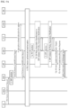
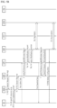
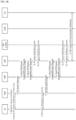
- FIGS. 6a and 6b illustrate a procedure for modifying a PDU session.
- the PDU Session Modification procedure may be initiated by the UE or by the network.
- the PDU Session Modification procedure may be initiated by the UE or by the network.
- the UE may initiate the PDU Session Modification procedure by transmitting an NAS message.
- the NAS message may include an N1 SM container.
- the N1 SM container may include a PDU Session Modification Request message, a PDU session ID, and information on integrity protection maximum data rate of the UE.
- the PDU Session Modification Request message may include a PDU session ID, a packet filter, information on requested QoS, 5GSM core network capability, and the number of packet filters.
- the integrity protection maximum data rate of the UE represents the maximum data rate allowed for the UE to support UP integrity protection.
- the number of packet filters represents the number of packet filters supported for a QoS rule.
- the NAS message is transmitted to an appropriate AMF via the RAN according to the location information of the UE. Then the AMF transmits Nsmf_PDUSession_UpdateSMContext message to the SMF.
- the message may include a Session Management (SM) context ID and an N1 SM container.
- the N1 SM container may include a PDU Session Modification Request message.
- the PCF may notify the SMF of a policy change by initiating an SM Policy Association Modification procedure.
- the UDM may update subscription data of the SMF by transmitting Nudm_SDM_Notification message.
- the SMF may update session management subscription data and transmit an ACK message to the UDM.
- the SMF may trigger a QoS update.
- the SMF may perform the PDU Session Modification procedure.
- the AN may notify the SMF of the resource release.
- the AN may transmit an N2 message to the AMF.
- the N2 message may include a PDU session ID and N2 SM information.
- the N2 SM information may include QFI, user location information, and an indication indicating release of a QoS flow.
- the AMF may transmit Nsmf_PDUSession_UpdateSMContext message.
- the message may include an SM context ID and N2 SM information.
- the SMF may transmit a report on a subscription event by performing an SM Policy Association Modification procedure. If the PDU Session Modification procedure is triggered by 1b to 1d cases, this step may be skipped. If dynamic PCC is not deployed over the network, the SMF may apply an internal policy to determine the change of the QoS profile.
- the steps 3 to 7 described below may not be performed when the PDU Session Modification procedure requires only the operation of the UPF.
- the SMF may respond to the AMF by transmitting Nsmf_PDUSession_UpdateSMContext message.
- the message may include N2 SM information and an N2 SM container.
- the N2 SM information may include a PDU session ID, QFI, a QoS profile, and a session-AMBR.
- the N1 SM container may include a PDU Session Modification command.
- the PDU Session Modification command may include a PDU session ID, a QoS rule, a QoS rule operation, QoS parameters at QoS flow level, and a session-AMBR.
- the N2 SM information may include information that the AM has to transmit to the AN.
- the N2 SM information may include QFI and a QoS profile to notify the AN that one or more QoS flows are added or modified. If PDU Session Modification is requested by a UE for which user plane resources are not configured, the N2 SM information to be transmitted to the AN may include information for establishment of user plane resources.
- the N1 SM container may include a PDU Session Modification command to be transmitted to the UE by the AMF.
- the PDU Session Modification command may include a QoS rule and QoS parameters at QoS flow level.
- the SMF may transmit Namf_Communication_N1N2MessageTransfer message.
- the message may include N2 SM information and an N1 SM container.
- the N2 SM information may include a PDU session ID, QFI, a QoS profile, and a session-AMBR.
- the N1 SM container may include a PDU Session Modification command.
- the PDU Session Modification command may include a PDU session ID, a QoS rule, and QoS parameters at QoS flow level.
- the AMF may skip steps 3 to 7 described below after updating and storing UE context based on the Namf_Communication_N1N2MessageTransfer message. If the UE enters a reachable state, namely, CM-CONNECTED state, the AMF may transmit an N1 message to synchronize the UE with the UE context.
- the AMF may transmit an N2 PDU Session Request message to the AN.
- the N2 PDU Session Request message may include the N2 SM information and the NAS message received from the SMF.
- the NAS message may include a PDU session ID and an N1 SM container.
- the N1 SM container may include a PDU Session Modification command.
- the AN performs AN signaling exchange with a UE associated with the information received from the SMF. For example, in the case of NG-RAN, to modify required AN resources associated with the PDU session, an RRC Connection Reconfiguration procedure may be performed in conjunction with the UE.
- the AN transmits an N2 PDU session ACK message in response to the received N2 PDU session request.
- the N2 PDU session ACK message may include N2 SM information and user location information.
- the N2 SM information may include a list of accepted / rejected QFI, AN tunnel information, and an PDU session ID.
- the AMF transmits the N2 SM information and the user location information received from the AN through Nsmf_PDUSession_UpdateSMContext message. Then the SMF transmits Nsmf_PDUSession_UpdateSMContext message to the AMF.
- the SMF transmits an N4 Session Modification Request message to the UPF to update the N4 session of the UPF included in the PDU Session Modification command.
- the SMF updates an UL packet detection rule of the new QoS flow together with the UPF.
- the UE transmits an NAS message in response to the reception of the PDU Session Modification command.
- the NAS message may include a PDU session ID and an N1 SM container.
- the N1 SM container may include a PDU Session Modification command ACK.
- the AN transmits the NAS message to the AMF.
- the AMF may transmit the N1 SM container and the user location information received from the AN to the SMF through Nsmf_PDUSession_UpdateSMContext message.
- the N1 SM container may include a PDU Session Modification command ACK.
- the SMF may transmit Nsmf_PDUSession_UpdateSMContext Response message to the AMF.
- the SMF transmits an N4 Session Modification Request message to the UPF to update the N4 session of the UPF included in the PDU Session Modification command.
- the message may include an N4 session ID.
- the SMF may notify the PCF of whether a PCC decision may be performed or not via the SM Policy Association Modification procedure.
- the SMF may notify an entity which has requested the user location information related to PDU Session Modification.
- the UE shall set the PDU session type IE in the PDU SESSION ESTABLISHMENT REQUEST message, based on its IP stack capabilities if the UE requests IP connectivity as follows:
- the UE If the UE wants to use DHCPv4 for IPv4 address assignment, it shall indicate that to the network within the Extended protocol configuration options IE in the PDU SESSION ESTABLISHMENT REQUEST.
- the network when allocating an IP address shall take into account the PDU session type IE, the operator's policies of the network, and the user's subscription data and:
- a PDU Session Modification procedure may be used to enable the UE to request PDU Session Modification.
- the UE shall create a PDU Session Modification Request message.
- the UE shall include the PDU session type IE in the PDU Session Modification Request message and shall set the PDU session type IE to the IP version capability.
- the UE should set the RQoS bit to "Reflective QoS supported" in the 5GSM capability IE of the PDU Session Modification Request message if the UE supports a reflective QoS,
- the SMF shall initiate the PDU Session Modification procedure requested by the network. To this end, the SMF shall create a PDU Session Modification Request message.
- the SMF shall set the selected PDU session type IE of the PDU Session Modification Request message to the selected PDU session type, i.e., the PDU session type of the PDU session.
- the SMF shall create a PDU Session Modification Reject message.
- the SMF shall set the 5GSM cause IE of the PDU Session Modification Reject message.
- the 5GSM cause IE indicates one of the following SM cause values.
- the SMF shall include the 5GSM cause value #28 "unknown PDU session type" in the 5GSM cause IE of the PDU Session Modification Reject message.
- the network may include a Back-off timer value IE in the PDU Session Modification Reject message.
- the UE shall ignore the Back-off timer value IE provided by the network.
- the UE shall evaluate the URSP rules if available.
- the UE shall not subsequently send another PDU Session Modification Request message for the same DNN and the same HPLMN S-NSSAI to obtain a PDU session type different from the one allowed by the network until any of the following conditions is fulfilled:
- the UE shall ignore the value of the RATC bit in the Re-attempt indicator IE provided by the network.
- ultra reliable low latency communications URLLC
- IIoT automation-centered industrial Internet of things
- the IEEE TSN technology refers to a kind of package technology, in which several existing IEEE standards are combined, and is regarded as the next-generation industrial network standards capable of covering most network applications extended from the standard Ethernet.
- 5G-TSN technology has been carrying forward standardization in earnest since Rel-16 to expand the vertical applications of 5G technology.
- the 5G-TSN technology is to integrate IEEE TSN technology into a 5G system (5GS), and refers to time-sensitive communications (TSC) that define and support various IIoT service requirements.
- TSC basically undergoes time synchronization between the 5GS and the TSN.
- TSC QoS Flow based on TSC assistance information (TSCAI) is supported.
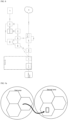
- FIG. 7 illustrates a network architecture of interworking with a TSN network.
- the 5GS may interwork with an external network through a TSN bridge.
- the logical TSN bridge may have TSN translator functionality to enable interaction between the 5GS and the TSN system for both the user plane and the control plane.
- the 5GS TSN translator functionality may include a device-side TSN translator (DS-TT) and a network-side TSN translator (NW-TT).
- DS-TT device-side TSN translator
- NW-TT network-side TSN translator
- the TSN AF is a part of the 5GC, and may provide control plane translator functionality to integrate the 5GS into the TSN. 5GS characteristic procedures, wireless communication links, etc. in the 5GC and RAN may not be shown in the TSN network.
- the 5GS provides TSN ingress and egress ports through the DS-TT and the NW-TT.
- the DS-TT may support a connection search and report of the link layer to find the Ethernet devices connected to the DS-TT.
- the NW-TT may support a connection search and report of the link layer to find the Ethernet devices connected to the NW-TT.
- the NW-TT may perform the connection search and report of the link layer on behalf of the DS-TT, thereby searching the Ethernet devices connected to the DS-TT.
- FIG. 8 illustrates an architecture of supporting time-sensitive communications and time synchronization services.
- the DS-TT, the NW-TT, and time sensitive communication and time synchronization function (TSCTSF) for supporting the time synchronization services for the Ethernet or IP type session are shown.
- the NEF provides the 5GS capability information to support the time synchronization service.
- the TSCTSF controls the DS-TT and the NW-TT.
- the UPF/NW-TT transmits a (g)PTP messages.
- the UPF supports one or more NW-TT
- the network instances may be considered to be separated logically.
- DetNet technology being developed by the IETF DetNet WG is a technology (Layer 3 technology) in which the application range of the Ethernet TSN technology (Layer 2 technology) is extended and integrated into IP- and MPLS-based networks.
- the DetNet technology refers to a technology that supports the extension of the Ethernet TSN technology (Layer 2 technology) to the IP technology (Layer 3 technology).
- the TSC framework extension technologies are reflected in the standards to support the IETF DetNet technology in the 5GS.
- IPv4, IPv6, IPv4v6, Ethernet (IEEE Std 802.3)
- unstructured types are supported.
- the UE configures one of IPv4, IPv6, IPv4v6, Ethernet (IEEE Std 802.3), and unstructured types and transmits in to the network as included in the PDU session type IE of the PDU Session Modification Request message.
- the disclosure of this specification proposes adding a new PDU session type for the industrial traffic and/or new capability information for the industrial traffic.
- the UE may configure the session type differently in order to recognize and distinguish the session for industrial traffic different from general traffic when transmitting the PDU Session Modification Request message to the network (i.e., SMF).
- the network i.e., SMF
- the network recognizes that the PDU session is for the industrial traffic other than the general traffic, and proceeds with the related QoS and session modification procedures by distinguishing that section from those for other traffics.
- the industrial traffic different from the general traffic refers to traffic for time-sensitive/deterministic or ultra-reliable low latency communication (URLLC) or industrial IoT (IIoT) or time-sensitive communication (TSC), or traffic of a related session.
- URLLC time-sensitive/deterministic or ultra-reliable low latency communication
- IIoT industrial IoT
- TSC time-sensitive communication
- the terminal (or user equipment (UE)) is receiving related communication service based on connection with a PDU session in an area where the industrial traffic is supported, and then moves to an area where the industrial traffic is not supported (or vice versa, i.e., it is receiving general communication service based on connection with the PDU session in the area where the industrial traffic is not supported, and then moves to the area where the industrial traffic is supported)
- CN 5G core network
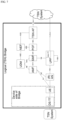
- FIG. 9a illustrate a scenario to which the disclosure of this specification is applied.
- FIG. 9a shows a first area and a second area.
- the first area may be an area for first industrial traffic, and the second area may be an area for second industrial traffic.
- the first area may be an area for a first TSN or first DetNet
- the second area may be an area for a second TSN or second DetNet.
- the first TSN and the second TSN may be different from each other.
- the first DetNet and the second DetNet may be different from each other.
- the first area may be an area for the first TSN or the second DetNet, but the second area may be an area where the TSN or DetNet is not supported.
- the first area may be an area where the TSN or DetNet is not supported, but the second area may be the area for the second TSN or second DetNet.
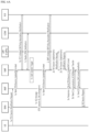
- FIG. 9b illustrates a procedure performed in the scenario illustrated in FIG. 9a , according to the disclosure of this specification.
- the UE may transmit the PDU Session Modification Request message that contains the PDU session type indicating the industrial traffic.
- the SMF may reject the PDU Session Modification request.
- the SMF creates and transmits a PDU Session Modification Reject message for the rejection.
- the PDU Session Modification Reject message may be delivered to the AMF through a Nsmf_PDUSession_UpdateSMContext response message.
- the AMF shall include the PDU Session Modification Reject message in the N2 message and transmit it to the RAN.
- the RAN shall transmit the PDU Session Modification Reject message to the UE as included in the PDU Session Modification instruction or PDU Session Modification ACK.
- a new cause value may be transmitted as included in the PDU Session Modification Reject message while rejecting the request of the UE.
- the UE that received the Reject message may transmit a PDU Session Modification Request message for configuring and requesting another PDU session type to the network.
- the industrial traffic different from the general traffic may refer to traffic for time-sensitive/deterministic or ultra-reliable low latency communication (URLLC) or industrial IoT (IIoT) or time-sensitive communication (TSC), or traffic of a related session.
- URLLC time-sensitive/deterministic or ultra-reliable low latency communication
- IIoT industrial IoT
- TSC time-sensitive communication
- the new cause value may be #xy: PDU Session Type TSN (or TSC, DetNet, IIoT, URLLC) only allowed.
- the UE i.e., terminal
- the UE may include PDU session type or capability information/indication in the PDU Session Modification Request message so that the network can recognize or distinguish the session for the industrial traffic, and transmit the PDU Session Modification Request message to the network (e.g., SMF). Then, the network (SMF) recognizes and distinguishes the session is for the industrial traffic and proceeds with a related QoS and session configuration procedure.
- the network e.g., SMF
- the new cause value may be #xy: PDU Session Type TSN (or TSC, DetNet, IIoT, URLLC) only allowed.
- the new PDU session type supported information for the industrial traffic may be transmitted as included in the 5GSM capability Information Element (IE) or Extended protocol configuration options IE.
- IE 5GSM capability Information Element
- IE Extended protocol configuration options
- the SMF shall create a message for indicating the rejection.
- the SMF shall set the 5GSM cause IE in the Reject message.
- the SMF shall include the 5GSM cause value #28 "unknown PDU session type" in the 5GSM cause IE of the Reject message.
- the network may include the Re-attempt indicator without the Back-off timer value to indicate whether the UE is allowed to attempt a PDU Session Modification procedure in an equivalent PLMN in N1 mode using the same PDU session type for the same DNN and the same S-NSSAI.
- the SMF shall send the Reject message.
- the UE shall receive the Reject message.
- the UE shall ignore the value of the RATC bit in the Re-attempt indicator IE provided by the network.
- FIG. 10 illustrates a procedure related to the disclosure of this specification.
- the terminal i.e., the UE may add the capability indication/information related to the industrial traffic separately from or together with the PDU session type indicating TSN (or TSC, DetNet, IIoT, URLLC) to the 5GSM capability Information Element (IE), Extended protocol configuration options IE or new IE of the PDU Session Modification Request message, and transmit it to the network.
- the PDU session type indicating TSN or TSC, DetNet, IIoT, URLLC
- IE 5GSM capability Information Element
- Extended protocol configuration options IE Extended protocol configuration options IE
- new IE new IE of the PDU Session Modification Request message
- the terminal i.e., the UE may add the capability indication/information related to the industrial traffic to the Additional Information Element (IE) or new IE of the UL NAS TRANSPORT message, and transmit it to the network.
- IE Additional Information Element
- the terminal i.e., the UE may add the capability indication/information related to the industrial traffic to the 5GMM capability Information Element (IE) or new IE of the Registration Request message, and transmit it to the network.
- IE 5GMM capability Information Element
- the industrial traffic different from the general traffic refers to traffic for time-sensitive/deterministic or ultra-reliable low latency communication (URLLC) or industrial IoT (IIoT) or time-sensitive communication (TSC), or traffic of a related session.
- URLLC time-sensitive/deterministic or ultra-reliable low latency communication
- IIoT industrial IoT
- TSC time-sensitive communication
- the capability, indication or configuration may refer to the capability, indication or configuration of the terminal, i.e., the UE to support/operate TSN (or DetNet), time-sensitive/deterministic, ultra-reliable low latency communication (URLLC), industrial IoT (IIoT) or time-sensitive communication (TSC).
- TSN or DetNet
- URLLC time-sensitive/deterministic, ultra-reliable low latency communication
- IIoT industrial IoT
- TSC time-sensitive communication
- the terminal i.e., the UE 100 configured with the TSN (or DetNet), time-sensitive/deterministic, ultra-reliable low latency communication (URLLC), industrial IoT (IIoT) or time-sensitive communication (TSC) or having that capability may perform/operate TSN (or DetNet), time-sensitive/deterministic, ultra-reliable low latency communication (URLLC), industrial IoT (IIoT) or time-sensitive communication (TSC), or transceive that service/traffic, and the terminal, i.e., UE configured as above or having that capability may be applied/operated according to the foregoing disclosure of this specification.
- TSN or DetNet
- URLLC time-sensitive/deterministic, ultra-reliable low latency communication
- IIoT industrial IoT
- TSC time-sensitive communication
- the terminal i.e., the UE 100 may be configured with TSN (or DetNet), time-sensitive/deterministic, ultra-reliable low latency communication (URLLC), industrial IoT (IIoT) or time-sensitive communication (TSC), or may have those capabilities.
- TSN or DetNet
- URLLC ultra-reliable low latency communication
- IIoT industrial IoT
- TSC time-sensitive communication
- the TSN (or DetNet), time-sensitive/deterministic, ultra-reliable low latency communication (URLLC), industrial IoT (IIoT) or time-sensitive communication (TSC) configuration, or the capability information may be pre-configured in the UE, i.e., UE (U)SIM, and may be provided and configured from the network (core network (CN)).
- the network (CN) may refer to an access and mobility management function (AMF) or session management function (SMF) of the 5G mobile communication network.
- AMF access and mobility management function
- SMF session management function
- the network may provide and configure the UE with the 5GS network feature support information element (IE) or new IE of the Registration Accept message in which the foregoing configuration or capability information/indication is included.
- IE 5GS network feature support information element
- the network may provide and configure the terminal, i.e., the UE with new information element (IE) of the Configuration Update Command message in which the foregoing configuration or capability information/indication is included.
- IE new information element
- the network may provide and configure the terminal, i.e., the UE with the Additional information element (IE) or new IE of the DL NAS TRANSPORT message in which the foregoing configuration or capability information/indication is included.
- the terminal i.e., the UE with the Additional information element (IE) or new IE of the DL NAS TRANSPORT message in which the foregoing configuration or capability information/indication is included.
- IE Additional information element
- new IE of the DL NAS TRANSPORT message in which the foregoing configuration or capability information/indication is included.
- the network may provide and configure the terminal, i.e., the UE with the management object (MO) in which the foregoing configuration or capability information/indication is included.
- the terminal i.e., the UE with the management object (MO) in which the foregoing configuration or capability information/indication is included.
- MO management object
- the extended protocol configuration option information element may be used for the following purposes:
- the extended protocol configuration option IE has a minimum length of 4 octets and a maximum length of 65538 octets.
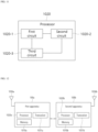
- FIG. 11 illustrates a block diagram of a processor in which the present disclosure is implemented.
- the processor 1020 in which the present disclosure is implemented may include a plurality of circuitry to implement functions, procedures and/or methods described in the present disclosure.
- the processor 1020 may include a first circuit 1020-1, a second circuit 1020-2, and a third circuit 1020-3.
- the processor 1020 may include more circuits. Each circuit may include a plurality of transistors.
- the processor 1020 may be called Application-Specific Integrated Circuit (ASIC) or Application Processor (AP) and may include at least one of a Digital Signal Processor (DSP), a Central Processing Unit (CPU), and a Graphics Processing Unit (GPU).
- ASIC Application-Specific Integrated Circuit
- AP Application Processor
- DSP Digital Signal Processor
- CPU Central Processing Unit
- GPU Graphics Processing Unit
- the processor may be equipped in the UE.
- FIG. 12 shows a wireless communication system according to an embodiment.
- a wireless communication system may include a first device 100a and a second device 100b.
- the first device 100a may be a terminal as described in the present disclosure.
- the first device 100a may be a base station, a network node, a transmitting terminal, a receiving terminal, a wireless device, a wireless communication device, a vehicle, a vehicle equipped with self-driving capability, a connected car, a drone (or an unmanned aerial vehicle (UAV)), an artificial intelligence (AI) module, a robot, an augmented reality (AR) device, a virtual reality (VR) device, a mixed reality (MR) device, a hologram device, a public safety device, an MTC device, an IoT device, a medical device, a FinTech device (or a financial device), a security device, a climate/environment device, a device related to a 5G service, or a device related to a field of the 4th industrial revolution.
- UAV unmanned aerial vehicle
- AI artificial intelligence
- AR augmented reality
- VR virtual reality
- MR mixed reality
- hologram device a public
- the second device 100b may be a network node (e.g., AMF or MME) as described in the present disclosure.
- the second device 100b may be a base station, a network node, a transmitting terminal, a receiving terminal, a wireless device, a wireless communication device, a vehicle, a vehicle equipped with self-driving capability, a connected car, a drone (or an unmanned aerial vehicle (UAV)), an artificial intelligence (AI) module, a robot, an augmented reality (AR) device, a virtual reality (VR) device, a mixed reality (MR) device, a hologram device, a public safety device, an MTC device, an IoT device, a medical device, a FinTech device (or a financial device), a security device, a climate/environment device, a device related to a 5G service, or a device related to a field of the 4th industrial revolution.
- a terminal may include a mobile phone, a smart phone, a laptop computer, a digital broadcasting terminal, a personal digital assistants (PDA), a portable multimedia player (PMP), a navigation, a slate PC, a table PC, an ultrabook, a wearable device (e.g., a smartwatch, a smart glass, a head mounted display (HMD)), or the like.
- the HMD may be a display device worn on a head.
- the HMD may be used to implement VR, AR, or MR.
- the drone may be an unmanned aerial vehicle which flies by using a radio control signal.
- the VR device may include a device for realizing an object, background, or the like of a virtual world.
- theR device may include a device for realizing an object or background of a virtual world by connecting with an object or background or the like of a real world.
- the MR device may include a device for realizing an object or background of a virtual world by merging an object, background, or the like of a real world.
- the hologram device may include a device for recording and reproducing stereoscopic information to realize a 360-degree stereoscopic image, by utilizing light interference which occurs when two laser beams called holography are met.
- the public safety device may include an image relay device or an image device or the like which can be worn on a user's body.
- the MTC device and the IoT device may be devices not requiring direct human intervention or manipulation.
- the MTC device and the IoT device may include a smart meter, a bending machine, a thermometer, a smart bulb, a door lock, or various sensors.
- the medical device may be a device used for diagnosing, curing, alleviating, treating, or preventing a disease.
- the medial device may be a device used for diagnosing, curing, alleviating or ameliorating an injury or disorder.
- the medial device may be a device used for inspecting, replacing, or modifying a structure or function.
- the medical device may be a device used for controlling pregnancy.
- the medical device may include a diagnostic device, a surgical device, a (in vitro) diagnostic device, a hearing aid, or a treatment device.
- the security device may be a device installed to prevent potential hazards and maintain security.
- the security device may be a camera, a CCTV, a recorder, or a black box.
- the Fin-Tech device may be a device capable of providing financial services such as mobile payment.
- the Fin-tech device may include a payment device or a point of sales (POS).
- the climate/environmental device may include a device for monitoring or predicting climates/environments.
- the first device 100a may include at least one processor such as a processor 1020a, at least one memory such as a memory 1010a, and at least one transceiver such as a transceiver 1031a.
- the processor 1020a may perform the aforementioned functions, procedures, and/or methods.
- the processor 1020a may perform one or more protocols.
- the processor 1020a may perform one or more layers of a radio interface protocol.
- the memory 1010a may be coupled to the processor 1020a, and may store various types of information and/or commands.
- the transceiver 1031a may be coupled to the processor 1020a, and may be controlled to transmit/receive a radio signal.
- the second device 100b may include at least one processor such as a processor 1020b, at least one memory such as a memory 1010b, and at least one transceiver such as a transceiver 1031b.
- the processor 1020b may perform the aforementioned functions, procedures, and/or methods.
- the processor 1020b may perform one or more protocols.
- the processor 1020b may perform one or more layers of a radio interface protocol.
- the memory 1010b may be coupled to the processor 1020b, and may store various types of information and/or commands.
- the transceiver 1031b may be coupled to the processor 1020b, and may be controlled to transmit/receive a radio signal.
- the memory 1010a and/or the memory 1010b may be connected internally or externally to the processor 1020a and/or the processor 1020b, respectively, or may be connected to other processors through various techniques such as wired or wireless connections.
- the first device 100a and/or the second device 100b may have one or more antennas.
- an antenna 1036a and/or an antenna 1036b may be configured to transmit/receive a radio signal.
- FIG. 13 is a block diagram of a network node according to an embodiment.
- FIG. 13 illustrates in detail the case where a base station is divided into a Central Unit (CU) and a Distributed Unit (DU).
- CU Central Unit
- DU Distributed Unit
- base stations W20 and W30 may be connected to a core network W10, and the base station W30 may be connected to the neighboring base station W20.
- NG an interface between the base stations W20 and W30 and the core network W10
- Xn an interface between the base station W30 and the neighboring base station W20
- the base station W30 may be divided into a CU W32 and DUs W34 and W36. That is, the base station W30 may be managed by being separated in a layered manner.
- the CU W32 may be connected to one or more DUs W34 and W36.
- an interface between the CU W32 and the DUs W34 and W36 may be referred to as F1.
- the CU W32 may perform a function of higher layers of the base station, and the DUs W34 and W36 may perform a function of lower layers of the base station.
- the CU W32 may be a logical node for hosting radio resource control (RRC), service data adaptation protocol (SDAP), and packet data convergence protocol (PDCP) layers of the base station (e.g., gNB), and the DUs W34 and W36 may be a logical node for hosting radio link control (RLC), media access control (MAC), and physical (PHY) layers of the base station.
- RRC radio resource control
- SDAP service data adaptation protocol
- PDCP packet data convergence protocol
- the DUs W34 and W36 may be a logical node for hosting radio link control (RLC), media access control (MAC), and physical (PHY) layers of the base station.
- RLC radio link control
- MAC media access control
- PHY physical
- the CU W32 may be a logical node for hosting RRC and PDCP layers of the base station (e.g., en-gNB).
- Operations of the DUs W34 and W36 may be partially controlled by the CU W32.
- One DU W34 or W36 may support one or more cells.
- One cell may be supported only by one DU W34 or W36.
- One DU W34 or W36 may be connected to one CU W32, and one DU W34 or W36 may be connected to a plurality of CUs by proper implementation.
- FIG. 14 is a block diagram showing a structure of a UE 100 according to an embodiment.
- FIG. 14 shows an example of the first device of FIG. 12 in greater detail.
- a terminal includes a memory 1010, a processor 1020, a transceiver 1031, a power management module 1091, a battery 1092, a display 1041, an input unit 1053, a speaker 1042, a microphone 1052, a subscriber identification module (SIM) card, and one or more antennas.
- SIM subscriber identification module
- the processor 1020 may be configured to implement the proposed functions, procedures, and/or methods described in the present specification. Layers of a radio interface protocol may be implemented in the processor 1020.
- the processor 1020 may include application-specific integrated circuits (ASICs), other chipsets, logic circuits, and/or data processing units.
- the processor 1020 may be an application processor (AP).
- the processor 1020 may include at least one of a digital signal processor (DSP), a central processing unit (CPU), a graphics processing unit (GPS), and a modulator and demodulator (modem).
- DSP digital signal processor
- CPU central processing unit
- GPS graphics processing unit
- modem modulator and demodulator
- processor 1020 may include an SNAPDRAGONTM series processor manufactured by Qualcomm ® , an EXYNOSTM series processor manufactured by Samsung ® , an A series processor manufactured by Apple ® , a HELIOTM series processor manufactured by MediaTek ® , an ATOMTM series processor manufactured by INTEL ® , or a corresponding next-generation processor.
- the power management module 1091 manages power for the processor 1020 and/or the transceiver 1031.
- the battery 1092 supplies power to the power management module 1091.
- the display 1041 outputs a result processed by the processor 1020.
- the input unit 1053 receives an input to be used by the processor 1020.
- the input unit 1053 may be displayed on the display 1041.
- the SIM card is an integrated circuit used to safely store an international mobile subscriber identity (IMSI) used to identify and authenticate a subscriber and a key related thereto in a portable phone and a portable phone device such as a computer. Contacts information may be stored in many SIM cards.
- IMSI international mobile subscriber identity
- the memory 1010 is operatively coupled to the processor 1020, and stores a variety of information for operating the processor 1020.
- the memory 1010 may include a read-only memory (ROM), a random access memory (RAM), a flash memory, a memory card, a storage medium, and/or other equivalent storage devices.
- ROM read-only memory
- RAM random access memory
- flash memory a non-transitory, persistent memory
- the module may be stored in the memory 1010 and may be performed by the processor 1020.
- the memory 1010 may be implemented inside the processor 1020. Alternatively, the memory 1010 may be implemented outside the processor 1020, and may be coupled to the processor 1020 in a communicable manner by using various well-known means.
- the transceiver 1031 is operatively coupled to the processor 1020, and transmits and/or receives a radio signal.
- the transceiver 1031 includes a transmitter and a receiver.
- the transceiver 1031 may include a baseband signal for processing a radio frequency signal.
- the transceiver controls one or more antennas to transmit and/or receive a radio signal.
- the processor 1020 transfers command information to the transceiver 1031, for example, to transmit a radio signal constituting voice communication data.
- the antenna serves to transmit and receive a radio signal.
- the transceiver 1031 may transfer a signal to be processed by the processor 1020, and may convert the signal into a baseband signal.
- the processed signal may be converted into audible or readable information which is output through the speaker 1042.
- the speaker 1042 outputs a result related to a sound processed by the processor 1020.
- the microphone 1052 receives a sound-related input to be used by the processor 1020.
- the processor 1020 receives the command information, and performs a proper function such as calling the phone number or the like. Operational data may be extracted from the SIM card or the memory 1010. In addition, the processor 1020 may display command information or operational information on the display 1041 for user's recognition and convenience.
- FIG. 15 is a detailed block diagram illustrating a transceiver of the first device shown in FIG. 12 or a transceiver of the UE shown in FIG. 14 .
- a transceiver 1031 includes a transmitter 1031-1 and a receiver 1031-2.
- the transmitter 1031-1 includes a Discrete Fourier Transform (DFT) unit 1031-11, a subcarrier mapper 1031-12, an IFFT unit 1031-13, a CP insertion unit 1031-14, a wireless transmitter 1031-15.
- the transceiver 1031 may further include a scramble unit (not shown), a modulation mapper (not shown), a layer mapper (not shown), and a layer permutator, and the transceiver 1031 may be disposed in front of the DFT unit 1031-11.
- the transmitter 1031-1 may transmit information to pass through the DFT unit 1031-11 before mapping a signal to a subcarrier.
- a signal spread (or pre-coded for the same meaning) by the DFT unit 1031-1 is subcarrier-mapped by the subcarrier mapper 1031-12, and then generated as a time domain signal by passing through the IFFT unit 1031-13.
- the DFT unit 1031-1 performs DFT on input symbols to output complex-valued symbols. For example, if Ntx symbols are input (here, Ntx is a natural number), a DFT size may be Ntx.
- the DFT unit 1031-11 may be called a transform precoder.
- the subcarrier mapper 1031-12 maps the complex-valued symbols to subcarriers of a frequency domain. The complex-valued symbols may be mapped to resource elements corresponding to a resource block allocated for data transmission.
- the subcarrier mapper 1031-12 may be called a resource element mapper.
- the IFFT unit 1031-3 may perform IFFT on input symbols to output a baseband signal for data, which is a time-domain signal.
- the CP inserter 1031-14 copies a rear portion of the baseband signal for data and inserts the copied portion into a front part of the baseband signal.
- the CP insertion prevents Inter-Symbol Interference (ISI) and Inter-Carrier Interference (ICI), and therefore, orthogonality may be maintained even in multi-path channels.
- ISI Inter-Symbol Interference
- ICI Inter-Carrier Interference
- the receiver 1031-2 includes a wireless receiver 1031-21, a CP remover 1031-22, an FFT unit 1031-23, and an equalizer 1031-24, and so on.
- the wireless receiver 1031-21, the CP remover 1031-22, and the FFT unit 1031-23 of the receiver 1031-2 performs functions inverse to functions of the wireless transmitter 1031-15, the CP inserter 1031-14, and the IFFT unit 1031-3 of the transmitter 1031-1.
- the receiver 1031-2 may further include a demodulator.
- FIG. 16 illustrates a communication system 1 to which the disclosure of this specification applies.
- the communication system 1 to which the disclosure of this specification applies includes a wireless device, a base station, and a network.
- a wireless device refers to a device that performs communication using wireless access technology (e.g., 5G NR (New RAT), LTE (Long Term Evolution)) and may be referred to as a communication/wireless/5G device.
- wireless devices include robots (100a), vehicles (100b-1, 100b-2), XR (eXtended Reality) devices (100c), hand-held devices (100d), and home appliances (100e). ), IoT (Internet of Thing) device (100f), and AI device/server
- vehicles may include vehicles equipped with wireless communication functions, autonomous vehicles, vehicles capable of inter-vehicle communication, etc.
- the vehicle may include an Unmanned Aerial Vehicle (UAV) (eg, a drone).
- UAV Unmanned Aerial Vehicle
- XR devices include AR (Augmented Reality)/VR (Virtual Reality)/MR (Mixed Reality) devices, HMD (Head-Mounted Device), HUD (Head-Up Display) installed in vehicles, televisions, smartphones, It can be implemented in the form of computers, wearable devices, home appliances, digital signage, vehicles, robots, etc.
- Portable devices may include smartphones, smart pads, wearable devices (e.g., smartwatches, smart glasses), and computers (e.g., laptops, etc.).
- Home appliances may include TVs, refrigerators, washing machines, etc.
- IoT devices may include sensors, smart meters, etc.
- a base station and network may also be implemented as wireless devices, and a specific wireless device 200a may operate as a base station/network node for other wireless devices.
- Wireless devices 100a to 100f may be connected to the network 300 through the base station 200.
- AI Artificial Intelligence
- the network 300 may be configured using a 3G network, 4G (eg, LTE) network, or 5G (eg, NR) network.
- Wireless devices 100a to 100f may communicate with each other through the base station 200/network 300, but may also communicate directly (e.g. sidelink communication) without going through the base station/network.
- vehicles 100b-1 and 100b-2 may communicate directly (e.g.
- V2V Vehicle to Vehicle
- V2X Vehicle to everything
- an IoT device eg, sensor
- another IoT device eg, sensor
- another wireless device 100a to 100f
- Wireless communication/connection may be established between the wireless devices (100a to 100f)/base station (200) and the base station (200)/base station (200).
- wireless communication/connection includes various wireless connections such as uplink/downlink communication (150a), sidelink communication (150b) (or D2D communication), and inter-base station communication (150c) (e.g. relay, IAB (Integrated Access Backhaul)).
- uplink/downlink communication 150a
- sidelink communication 150b
- inter-base station communication 150c
- This can be achieved through technology (e.g., 5G NR).
- a wireless device and a base station/wireless device, and a base station and a base station can transmit/receive wireless signals to each other.
- wireless communication/ connection 150a, 150b, 150c can transmit/receive signals through various physical channels.
- transmit/receive wireless signals At least some of various configuration information setting processes, various signal processing processes (e.g., channel encoding/decoding, modulation/demodulation, resource mapping/demapping, etc.), resource allocation processes, etc. may be performed.
Landscapes
- Engineering & Computer Science (AREA)
- Computer Networks & Wireless Communication (AREA)
- Signal Processing (AREA)
- Health & Medical Sciences (AREA)
- Computing Systems (AREA)
- General Health & Medical Sciences (AREA)
- Medical Informatics (AREA)
- Mobile Radio Communication Systems (AREA)
- Communication Control (AREA)
Applications Claiming Priority (3)
| Application Number | Priority Date | Filing Date | Title |
|---|---|---|---|
| KR20220083711 | 2022-07-07 | ||
| KR1020230078430A KR20240007067A (ko) | 2022-07-07 | 2023-06-19 | 산업용 트래픽을 위한 pdu 세션 수정 절차 |
| PCT/KR2023/008947 WO2024010267A1 (ko) | 2022-07-07 | 2023-06-27 | 산업용 트래픽을 위한 pdu 세션 수정 절차 |
Publications (1)
| Publication Number | Publication Date |
|---|---|
| EP4529344A1 true EP4529344A1 (de) | 2025-03-26 |
Family
ID=89453734
Family Applications (1)
| Application Number | Title | Priority Date | Filing Date |
|---|---|---|---|
| EP23835734.7A Pending EP4529344A1 (de) | 2022-07-07 | 2023-06-27 | Pdu-sitzungsmodifizierungsverfahren für industriellen verkehr |
Country Status (4)
| Country | Link |
|---|---|
| US (1) | US20250150510A1 (de) |
| EP (1) | EP4529344A1 (de) |
| CN (1) | CN119498020A (de) |
| WO (1) | WO2024010267A1 (de) |
Family Cites Families (5)
| Publication number | Priority date | Publication date | Assignee | Title |
|---|---|---|---|---|
| CN111200848B (zh) * | 2018-11-19 | 2022-03-25 | 华为技术有限公司 | 一种通信方法及装置 |
| US11792871B2 (en) * | 2019-01-08 | 2023-10-17 | Nec Corporation | Core network node and method for handling redundant URLLC connections |
| CN111490841B (zh) * | 2020-03-23 | 2024-05-31 | 腾讯科技(深圳)有限公司 | 用于实现时间同步的方法及相关设备 |
| KR20210143563A (ko) * | 2020-05-20 | 2021-11-29 | 삼성전자주식회사 | 이동통신 네트워크에서 단말에 Deterministic Communication을 지원하는 방법 및 장치 |
| US12010549B2 (en) * | 2020-10-08 | 2024-06-11 | Mediatek Inc. | Handling of 5GSM congestion timers |
-
2023
- 2023-06-27 EP EP23835734.7A patent/EP4529344A1/de active Pending
- 2023-06-27 WO PCT/KR2023/008947 patent/WO2024010267A1/ko not_active Ceased
- 2023-06-27 CN CN202380051989.6A patent/CN119498020A/zh active Pending
-
2025
- 2025-01-03 US US19/009,364 patent/US20250150510A1/en active Pending
Also Published As
| Publication number | Publication date |
|---|---|
| US20250150510A1 (en) | 2025-05-08 |
| CN119498020A (zh) | 2025-02-21 |
| WO2024010267A1 (ko) | 2024-01-11 |
Similar Documents
| Publication | Publication Date | Title |
|---|---|---|
| KR102701230B1 (ko) | 비구조화 트래픽을 중계하기 위한 방법 및 릴레이 ue | |
| US12200595B2 (en) | Path-switching between PC5 link and UU link | |
| CN114557031B (zh) | 用于将非3gpp上的pdu会话移动到3gpp接入的方法 | |
| CN114600504A (zh) | 用于将非3gpp上的ims语音会话移动到3gpp接入的方法 | |
| US12003549B2 (en) | Method and terminal for processing security policy for V2X | |
| EP4021138B1 (de) | Behandlung einer empfangenen rrc-verbindungsrekonfigurationsnachricht durch ein relais-ue | |
| CN115715473B (zh) | 通过改进nwdaf的功能使smf有效执行冗余传输的方法 | |
| KR102633032B1 (ko) | Nwdaf의 분석 정보를 이용하는 smf의 동작 방법 | |
| EP4117390A1 (de) | Schema zum auswählen eines smf-knotens | |
| EP4213523A1 (de) | Verfahren zur berücksichtigung der sicherheitsanwendungsrichtlinie zwischen pc5-verbindung und uu-verbindung in der prose-relais-kommunikation und vorrichtung zur unterstützung davon | |
| US20250126550A1 (en) | Pdu session establishment procedure for industrial traffic | |
| KR20230174728A (ko) | 산업용 트래픽을 위한 pdu 세션 수립 절차 | |
| EP4529344A1 (de) | Pdu-sitzungsmodifizierungsverfahren für industriellen verkehr | |
| EP4546877A1 (de) | Zugangskontrollmechanismus zur signalisierung oder daten für industriellen verkehr | |
| US20250193727A1 (en) | Efficient congestion control for industrial traffic in 3gpp 5gs | |
| KR20240007067A (ko) | 산업용 트래픽을 위한 pdu 세션 수정 절차 | |
| EP4496422A1 (de) | Verfahren zum umschalten zwischen uu und pc5 | |
| EP4568306A1 (de) | Lbo-modus-pdu-sitzung | |
| KR20250114639A (ko) | 무선 통신 시스템에서 서비스 지역을 고려한 네트워크 슬라이싱의 올웨이즈-온 pdu 세션 처리 방법 및 장치 | |
| KR20240007074A (ko) | 산업용 트래픽을 위한 시그널링 또는 데이터에 대한액세스 제어 메커니즘 | |
| KR20250084474A (ko) | 무선 통신 시스템에서 서비스 지역을 고려한 네트워크 슬라이싱의 올웨이즈-온(always-on) PDU(protocol data unit) 세션 처리 방법 및 장치 | |
| KR20250084473A (ko) | 무선 통신 시스템에서 서비스 지역을 고려한 네트워크 슬라이싱의 PDU(protocol data unit) 세션 처리 방법 및 장치 | |
| KR20250114638A (ko) | 무선 통신 시스템에서 서비스 지역을 고려한 네트워크 슬라이싱의 pdu 세션 처리 방법 및 장치 | |
| KR20250114636A (ko) | 무선 통신 시스템에서 네트워크 슬라이싱의 pdu 세션 처리 방법 및 장치 | |
| KR20250031379A (ko) | 무선 통신 시스템에서 네트워크 슬라이싱의 PDU(protocol data unit) 세션 처리 방법 및 장치 |
Legal Events
| Date | Code | Title | Description |
|---|---|---|---|
| STAA | Information on the status of an ep patent application or granted ep patent |
Free format text: STATUS: THE INTERNATIONAL PUBLICATION HAS BEEN MADE |
|
| PUAI | Public reference made under article 153(3) epc to a published international application that has entered the european phase |
Free format text: ORIGINAL CODE: 0009012 |
|
| STAA | Information on the status of an ep patent application or granted ep patent |
Free format text: STATUS: REQUEST FOR EXAMINATION WAS MADE |
|
| 17P | Request for examination filed |
Effective date: 20241218 |
|
| AK | Designated contracting states |
Kind code of ref document: A1 Designated state(s): AL AT BE BG CH CY CZ DE DK EE ES FI FR GB GR HR HU IE IS IT LI LT LU LV MC ME MK MT NL NO PL PT RO RS SE SI SK SM TR |
|
| DAV | Request for validation of the european patent (deleted) | ||
| DAX | Request for extension of the european patent (deleted) |