EP4529319A1 - Informationsübertragungsverfahren, kommunikationsknoten und speichermedium - Google Patents
Informationsübertragungsverfahren, kommunikationsknoten und speichermedium Download PDFInfo
- Publication number
- EP4529319A1 EP4529319A1 EP23819150.6A EP23819150A EP4529319A1 EP 4529319 A1 EP4529319 A1 EP 4529319A1 EP 23819150 A EP23819150 A EP 23819150A EP 4529319 A1 EP4529319 A1 EP 4529319A1
- Authority
- EP
- European Patent Office
- Prior art keywords
- communication node
- data packet
- location information
- pilots
- information
- Prior art date
- Legal status (The legal status is an assumption and is not a legal conclusion. Google has not performed a legal analysis and makes no representation as to the accuracy of the status listed.)
- Pending
Links
Images


Classifications
-
- H—ELECTRICITY
- H04—ELECTRIC COMMUNICATION TECHNIQUE
- H04W—WIRELESS COMMUNICATION NETWORKS
- H04W76/00—Connection management
- H04W76/20—Manipulation of established connections
- H04W76/27—Transitions between radio resource control [RRC] states
-
- H—ELECTRICITY
- H04—ELECTRIC COMMUNICATION TECHNIQUE
- H04W—WIRELESS COMMUNICATION NETWORKS
- H04W76/00—Connection management
- H04W76/10—Connection setup
- H04W76/11—Allocation or use of connection identifiers
-
- H—ELECTRICITY
- H04—ELECTRIC COMMUNICATION TECHNIQUE
- H04L—TRANSMISSION OF DIGITAL INFORMATION, e.g. TELEGRAPHIC COMMUNICATION
- H04L5/00—Arrangements affording multiple use of the transmission path
- H04L5/003—Arrangements for allocating sub-channels of the transmission path
- H04L5/0048—Allocation of pilot signals, i.e. of signals known to the receiver
- H04L5/0051—Allocation of pilot signals, i.e. of signals known to the receiver of dedicated pilots, i.e. pilots destined for a single user or terminal
-
- H—ELECTRICITY
- H04—ELECTRIC COMMUNICATION TECHNIQUE
- H04L—TRANSMISSION OF DIGITAL INFORMATION, e.g. TELEGRAPHIC COMMUNICATION
- H04L5/00—Arrangements affording multiple use of the transmission path
- H04L5/003—Arrangements for allocating sub-channels of the transmission path
- H04L5/0053—Allocation of signalling, i.e. of overhead other than pilot signals
-
- H—ELECTRICITY
- H04—ELECTRIC COMMUNICATION TECHNIQUE
- H04L—TRANSMISSION OF DIGITAL INFORMATION, e.g. TELEGRAPHIC COMMUNICATION
- H04L5/00—Arrangements affording multiple use of the transmission path
- H04L5/003—Arrangements for allocating sub-channels of the transmission path
- H04L5/0058—Allocation criteria
- H04L5/0069—Allocation based on distance or geographical location
-
- H—ELECTRICITY
- H04—ELECTRIC COMMUNICATION TECHNIQUE
- H04L—TRANSMISSION OF DIGITAL INFORMATION, e.g. TELEGRAPHIC COMMUNICATION
- H04L5/00—Arrangements affording multiple use of the transmission path
- H04L5/0091—Signalling for the administration of the divided path, e.g. signalling of configuration information
- H04L5/0094—Indication of how sub-channels of the path are allocated
-
- H—ELECTRICITY
- H04—ELECTRIC COMMUNICATION TECHNIQUE
- H04W—WIRELESS COMMUNICATION NETWORKS
- H04W4/00—Services specially adapted for wireless communication networks; Facilities therefor
- H04W4/02—Services making use of location information
-
- H—ELECTRICITY
- H04—ELECTRIC COMMUNICATION TECHNIQUE
- H04W—WIRELESS COMMUNICATION NETWORKS
- H04W4/00—Services specially adapted for wireless communication networks; Facilities therefor
- H04W4/80—Services using short range communication, e.g. near-field communication [NFC], radio-frequency identification [RFID] or low energy communication
-
- H—ELECTRICITY
- H04—ELECTRIC COMMUNICATION TECHNIQUE
- H04W—WIRELESS COMMUNICATION NETWORKS
- H04W64/00—Locating users or terminals or network equipment for network management purposes, e.g. mobility management
-
- H—ELECTRICITY
- H04—ELECTRIC COMMUNICATION TECHNIQUE
- H04W—WIRELESS COMMUNICATION NETWORKS
- H04W72/00—Local resource management
- H04W72/04—Wireless resource allocation
- H04W72/044—Wireless resource allocation based on the type of the allocated resource
-
- H—ELECTRICITY
- H04—ELECTRIC COMMUNICATION TECHNIQUE
- H04W—WIRELESS COMMUNICATION NETWORKS
- H04W64/00—Locating users or terminals or network equipment for network management purposes, e.g. mobility management
- H04W64/006—Locating users or terminals or network equipment for network management purposes, e.g. mobility management with additional information processing, e.g. for direction or speed determination
Definitions
- the present application relates to the field of communication technology, for example, an information transmission method, a communication node, and a storage medium.
- Integration of sensing and communication refers to the integration of two functions of communication and sensing so that future communication systems have such two functions. Future wireless communication systems will have needs for ISAC.
- an important scenario in future wireless communication systems is Internet of things (IoT) or Massive Machine-Type Communications (mMTC).
- IoT Internet of things
- mMTC Massive Machine-Type Communications
- an important type of service needs to acquire location information of User Equipment (UE).
- UE User Equipment
- the present application provides an information transmission method, a communication node, and a storage medium.
- Embodiments of the present application provide an information transmission method.
- the method is applied to a first communication node and includes the following.
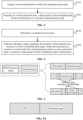
- a data packet including the location information is transmitted to a second communication node.
- Embodiments of the present application also provide an information transmission method.
- the method is applied to a second communication node and includes the following.
- a transmission resource is determined.
- the location of the transmission resource is indicated to a first communication node, where the transmission resource is used by the first communication node in a non-connected state to transmit a data packet including location information.
- An embodiment of the present application also provides a communication node.
- the communication node includes one or more processors and a storage apparatus configured to store one or more programs.
- the one or more programs When executed by the one or more processors, the one or more programs cause the one or more processors to perform the preceding information transmission method.
- An embodiment of the present application also provides a computer-readable storage medium.
- the computer-readable storage medium stores a computer program that, when executed by a processor, causes the processor to perform the preceding information transmission method.
- Procedures illustrated in flowcharts among the drawings may be executed by, for example, a computer system capable of executing a set of computer-executable instructions. Moreover, although logical sequences are illustrated in the flowcharts, the procedures illustrated or described may be performed in sequences different from those described herein in some cases.
- future wireless communication systems may include the following three requirements.
- systems achieve easier and more accurate multi-user pairing and scheduling, beamforming, energy saving of base stations, and other purposes.
- Monitoring of pedestrians, vehicle traffic, and other aspects is achieved to assist transportation and can also be used as information to assist public governance.
- Perceiving the number of terminals in a place is achieved, and then security functions are implemented by communication signals.
- Future wireless communication systems also have the requirement to better support IoT/mMTC. If the systems can acquire the location information of a large number of terminals, the systems can provide better IoT services, such as asset tracking, logistics management, and child/elderly/pet anti-lost services.
- FIG. 1A is a diagram illustrating the implementation of acquiring location information of a terminal according to an embodiment.
- 1 represents a base station
- 2 represents a building
- 3 represents a terminal.
- the base station 1 can acquire a large quantity of location information of the terminal 3 at different locations (such as location 1, location 2, ... location K) and can also acquire channel information (such as channel 1, channel 2, ... channel K) experienced by wireless signals transmitted by the terminals 3.
- FIG. 1B is a diagram illustrating the implementation of monitoring condition information of weather according to an embodiment. As shown in FIG. 1B , 4 represents rain and snow. The corresponding weather conditions of rain and snow can be sensed by the location information of terminal 3.
- FIG. 1C is a diagram illustrating the implementation of monitoring dust information according to an embodiment. As shown in FIG. 1C , 5 represents dust. The corresponding condition of dust can be sensed by the location information of terminal 3.
- the transmission of the location information of a terminal increases power consumption of the terminal. Therefore, most private users' terminals may resist the requirement of "transmitting your own location information". For example, if the function of "transmitting your own location information" is optional, many users may turn off this function. Alternatively, some terminals may use transmitting no location information as a point of attracting users. These conflicts greatly reduce the number of terminals that can provide location information and ultimately reduce the performance of related solutions that rely on "location information and corresponding wireless channel information thereof (wireless channel information is the channel information experienced by the wireless signal transmitted by a terminal)".
- related uplink information transmission or uplink data transmission first requires a terminal (that is, UE) to be in a connected state.
- the connected state may also be referred to as a radio resource control (RRC) connected state.
- RRC radio resource control
- a terminal in the connected state generally does not have a dedicated uplink transmission resource. Therefore, the terminal in the connected state needs to apply for an uplink transmission resource from a base station each time before transmitting data.
- the terminal After acquiring the grant of an uplink resource from the base station, the terminal can transmit data on a time-frequency resource designated by the base station. It can be seen that in order for the terminal to complete an uplink data transmission, many operations need to be completed in advance. If the terminal is required to transmit location information by a related uplink data transmission mechanism, power consumption of transmitting location information by the terminal is significantly increased, and signaling overheads of the system are also increased. More specific analysis is as follows.
- a terminal transmits location information at a very low frequency.
- location information is transmitted once every few seconds, tens of seconds, or even minutes.
- the terminal is generally in an idle state or an inactive state of deep sleep to save power.
- the terminal usually does not enter the connected state (that is, the terminal is not in the connected state).
- the terminal needs to perform some operations when accessing a connected state or maintaining a connected state, which increases the power consumption of the terminal, while these operations are not required when the terminal is in an unconnected state, that is, the idle state or the inactive state, which saves power.
- the terminal when the terminal does not need to transmit location information or has no other service, the terminal usually has no connection with the system (that is, disconnected), that is, the terminal is in an unconnected state (Non-connected state, non RRC connected state, connectionless state, connection-free state, or disconnected state can all represent unconnected state).
- the idle state or inactive state may be considered to be equivalent to an unconnected state or may be considered as an unconnected state.
- the terminal When the terminal is originally in an unconnected state (that is, the terminal has not entered the connected state or has not established a connection with the system), if the relevant uplink data transmission scheme is used, the terminal must establish a connection with the system before transmission to transmit the location information. After entering the connected state (also referred to as an active state), the terminal can then further apply for an uplink transmission resource from the system (such as a base station or an access point). Only after acquiring resource grant or resource scheduling of the system can the actual location information be transmitted. A random access process is required for the terminal to enter the connected state from the unconnected state. This random access process requires multiple interactions between the terminal and the base station.
- the terminal sends a preamble, the base station makes a random access response (RAR), the terminal sends layer2 (L2) or layer3 (L3) control information, and the base station sends a message 4.
- RAR random access response
- L2 layer2
- L3 layer3
- the preceding related uplink data transmission scheme is used, and if a large number of terminals that need to transmit location information are required and a large number of terminals need to enter the connected state before transmitting location information, a large number of terminals will have a random access process and then apply for the grunt of uplink resources. A large number of terminals indicate that random access processes will have a high probability of collision or blocking. As a result, many terminals need multiple access attempts to succeed. The final result is that the energy and signaling consumed by the terminals to complete the task of transmitting location information further significantly increases. It can be seen that the preceding related uplink data transmission scheme is not suitable for the application scenario where a large number of terminals transmit location information.
- another mode of related uplink data transmission may be semi-persistent scheduling (SPS).
- SPS aims to reduce the physical control signaling overheads and latency of small data packet services and is very suitable for periodic services, such as voice over IP (VoIP).
- VoIP voice over IP
- the data rate of VoIP is basically constant during a talkspurt, and a voice packet is generated every 20 ms. Each talkspurt lasts an average of 1-2 seconds, including 50-100 voice packets.
- the small-scale fading during this period is compensated by closed-loop power control to ensure that the signal-to-noise ratio (SNR) of a signal on the receiving side is basically constant.
- SNR signal-to-noise ratio
- SPS modulation and coding scheme
- SPS may be considered as an enhanced form of semi-static configuration, mainly used for periodic small-packet services with constant packet size. SPS generally works in the connected state (RRC Connected), that is, the terminal has completed the initial access process.
- RRC Connected the connected state
- the frequency of scheduling is far lower than the frequency at which a data packet arrives, the scheduling is basically non-competitive, and different users do not have resource collisions, such as reference signal/pilot collisions.
- the evolved SPS may be used in an ultra-reliable and low latency communications (URLLC) scenario, which ensures high reliability on the one hand and reduces the latency on the user plane on the other hand.
- SPS may also be referred to as configured grant, that is, pre-configured resource grant.
- Configured grant is also considered a special grant-free mode or scheduling-free mode because configured grant can avoid the "dynamic grant application” or “dynamic scheduling application” for each data transmission.
- configured grant is "dynamic grant-free” or “dynamic scheduling-free”.
- the pre-configured scheduling-free mode such as SPS or configured grant can reduce the overheads of physical control signaling for uplink transmission, the spectral efficiency of the system is still very low if SPS is still used to report location information of a large number of users.
- the reason is as follows: If a terminal applies for a periodic transmission resource in a cell for a period of time, but the terminal performs handoff during this process, the terminal needs to apply for a new pre-configured transmission resource from the cell entered by the terminal and meanwhile notify the cell the terminal leaves to release the pre-configured resource previously allocated to the terminal. It is a complicated process for the terminal to reapply for a transmission resource from the newly entered cell.
- a random access process is also required in the newly entered multiple cells, which significantly increases power consumption of the terminal and signaling overheads of the system.
- the terminal does not transmit the location information too frequently to save power, that is, the terminal sends the location information once after a relatively long interval. Therefore, to improve efficiency, the interval between pre-configured resources is usually relatively long, indicating that adverse effects caused by handoff are significantly increased. In this manner, spectral efficiency of the system is significantly reduced, and system complexity is increased. Even if different terminals or nodes are fixed, the environment around the terminals or nodes is very likely to change over a long period of time, leading to handoff, especially for terminals or nodes at the edge of a cell.
- the SPS pre-configuration mechanism can implement scheduling-free transmission or grant-free transmission, the SPS pre-configuration mechanism is not suitable for the application scenario where a large number of terminals transmit location information.
- a specific signal that is, a data packet at least including location information in a non-connected state
- a terminal can meet the needs of the preceding ISAC and IoT/mMTC.
- power consumption of the terminal can be reduced, the problem of power consumption caused by the terminal transmitting location information is greatly alleviated, and the user's concerns about the power consumption caused by transmitting location information are reduced.
- the function of "transmitting your own location information" can be made a mandatory function of the terminal or can be made an obligatory or mandatory function of the terminal.
- each terminal needs to have this function to pass the authentication when authenticated for network access, and this function cannot be turned off to prevent the terminal from turning off this function after passing the authentication.
- this function cannot be turned off to prevent the terminal from turning off this function after passing the authentication.
- the number of terminals that can provide location information can be greatly increased, thereby improving performance of various solutions based on "location information" or "location information and wireless channel information corresponding to the location information”.
- FIG. 2 is a flowchart of an information transmission method according to an embodiment. As shown in FIG. 2 , the method provided in this embodiment may be applied to a first communication node (that is, UE) and includes S110 and S120.
- a first communication node that is, UE
- the first communication node may be considered as a terminal device (that is, UE).
- the location information may be understood as information representing the current location (such as a geographical location) of the first communication node.
- the first communication node may acquire its current location information. No limitation is imposed herein on how to acquire the location information of the first communication node.
- the first communication node may acquire and position the current location information of the first communication node by a positioning module set up by the first communication node.
- the first communication node may receive the location information from another place.
- a base station transmits the calculated location information of the first communication node to the first communication node, and the first communication node receives the location information.
- a data packet at least including the location information is transmitted to a second communication node.
- the non-connected state may be considered as the unconnected state mentioned above, and the non-connected state may also be referred to as an idle state or an inactive state.
- the data packet may be understood as a data unit used for transmitting data in a communication process.
- the data packet includes data to be transmitted.
- the data packet including location information may also include identity-related information corresponding to the first communication node or may not include identity-related information corresponding to the first communication node.
- the identity-related information may be understood as information that represents the identity of the first communication node.
- the identity-related information may uniquely identify the first communication node and may be considered as a label of the first communication node. It should be noted that operations such as acquisition, storage, use, and processing of identity-related information in the present application comply with the relevant provisions of national laws and regulations.
- the first communication node may transmit, in a non-connected state, the data packet at least including location information to the second communication node.
- the signaling indicating the location of the transmission resource and transmitted by the second communication node may be received to transmit the data packet based on a time-frequency resource in the indicated transmission resource.
- the location information of the first communication node is transmitted.
- the first communication node does not need to establish a connection with the second communication node in advance, nor does the first communication node need to request the second communication node to allocate a dedicated resource for uplink transmission of data to the first communication node, thereby avoiding the power consumption of the first communication node in establishing a connection.
- the first communication node does not need to release the corresponding connection at this time, which further avoids the increase in power consumption. Therefore, in this embodiment, the acquired location information of the first communication node is transmitted to the corresponding second communication node in the non-connected state so that the increase in power consumption caused by repeated interaction in establishing a connection with the second communication node can be avoided.
- the method also includes the following.
- a target signaling is acquired.
- a transmission resource configured or defined by the second communication node is determined, where the transmission resource is used by the first communication node in a non-connected state to transmit the data packet at least including location information.
- the target signaling may be understood as a signaling that is used to configure or define the location of a transmission resource.
- the transmission resource may be understood as a common time-frequency resource used by the first communication node in a non-connected state to transmit the data packet at least including location information, that is, the transmission resource may include multiple time-frequency resources.
- the transmission resource may be a common resource defined or configured by the second communication node.
- the target signaling may be a broadcast signaling defined by the second communication node to indicate the location of the transmission resource. Based on this, the first communication node may acquire a target signaling transmitted by the second communication node, and determine, based on the target signaling, a transmission resource configured or defined by the second communication node.
- transmitting the data packet at least including the location information to the second communication node includes the following.
- a time-frequency resource is selected in the transmission resource.
- the data packet at least including the location information is transmitted to the second communication node on the time-frequency resource.
- the first communication node selects a time-frequency resource in the transmission resource to transmit, on the time-frequency resource, the data packet at least including the location information to the corresponding second communication node.
- the first communication node selects a time-frequency resource in the transmission resource.
- the first communication node may designate, as required, a time-frequency resource in the transmission resource for transmitting the location information.
- transmitting the data packet at least including the location information to the second communication node includes the following.
- the data packet at least including the location information and the W pilots are transmitted to the second communication node together; where W is greater than 1.
- wireless communications generally need to insert a pilot into a transmitted signal or transmitted data packet so that the receiver (that is, the second communication node) first estimates, by the pilot, a channel and a time frequency offset experienced by the transmitted signal or the transmitted data packet, thereby implementing the demodulation of data symbols in the data packet.
- the pilot included in the transmitted signal or transmitted data packet may also be referred to as a pilot signal, a reference signal (RS), or a demodulation reference signal (DMRS).
- RS reference signal
- DMRS demodulation reference signal
- the pilot is usually a sequence or a string of symbols, so the pilot may also be referred to as a pilot sequence.
- the first communication node may first determine W pilots (W is greater than 1, which means that at least two pilots are determined first). Based on this, the data packet at least including the location information and the W pilots may be transmitted to the corresponding second communication node together.
- the pilots are not specifically limited herein.
- the pilots may be extremely sparse pilots or independent multi-pilots.
- the position of the pilots may be contained in the data packet (such as in the middle of the data packet) or outside the data packet (such as in front of or behind the data packet), which is not limited herein.
- the first communication node may autonomously select a pilot or autonomously generate a pilot.
- the first communication node in a non-connected state, transmits the data packet at least including the location information of the first communication node to the second communication node.
- the first communication node since the first communication node does not enter a connected state during transmission, the first communication node cannot acquire the pilots specified by the second communication node (such as a base station or an access point), so the pilots used when the first communication node transmits the data packet may be selected or generated by the first communication node autonomously.
- Selecting pilots may indicate that the first communication node selects the pilots from a preset pilot set.
- Generating pilots may indicate that the first communication node generates the pilots according to a preset rule or formula.
- pilots generated according to the preset rule or formula herein also constitute a preset pilot set, so it can be understood that generating pilots according to a preset rule or formula is equivalent to selecting pilots in a preset pilot set, and the two may be understood as the same thing.
- the selection of pilots in a preset pilot set is used as an example for explanation. It can be learned that the autonomous pilot selection may indicate that the terminal (that is, the first communication node) may decide how to select pilots from a preset pilot set without the need for signaling instructions or arrangements from the second communication node (that is, the base station or access point) to determine the pilots to be transmitted in a non-connected state.
- the terminal transmits, in a non-connected state, the data packet at least including the location information of the terminal to the base station or the access point, and the pilots included in the transmission may be selected autonomously by the terminal, that is, the pilots included in the transmission are determined autonomously by the terminal.
- the W pilots are independent and unrelated.
- the determined W pilots are independent and unrelated. That is, it may be understood that no correlation exists between the W pilots or the W pilots are unrelated to each other.
- the determined W pilots are independent and unrelated, indicating that even after the base station knows one of the pilots, the base station cannot infer other (W-1) pilots from the pilot.
- the W pilots are determined according to information in the transmitted data packet.
- the W pilots may be determined according to information in the data packet transmitted together. No specific limitation is imposed herein on how to determine W pilots using the information in the transmitted data packet.
- the information in the transmitted data packet may also include information for determining W pilots, for example, information such as index numbers of the W pilots in a pilot set, the initial state of generated pilots, or information in the transmitted data packet reused to indicate the index numbers of the W pilots in a pilot set or the initial state of generated pilots.
- the corresponding W pilots may be determined according to information such as index numbers of the W pilots in a pilot set or the initial state of generated pilots.
- the related information for determining the W pilots is included in the transmitted data packet to determine the W pilots by the related information included in the data packet. Therefore, an additional piece of information used to indicate the W pilots does not need to be added in the transmission process.
- the related information may be the original information in the data packet, and the original information is reused to indicate the index numbers of the W pilots, the initial state of generated pilots, or other pieces of information identifying the pilots. In this manner, once the data packet of a terminal is successfully decoded, the information of all the pilots used by the terminal in this transmission can be known, and then all the pilots can be reconstructed. Thus, the interference of the pilot signals can be eliminated.
- the W pilots are determined according to one or more bits in the transmitted data packet.
- one or more bits are required to determine each pilot, and these bits may be the original bits in the transmitted data packet, that is, the original bits in the transmitted data packet are reused to indicate the index numbers of the W pilots, the initial state of generated pilots, or other pieces of information identifying the pilots.
- bits representing location information may be used to indicate the index numbers of the W pilots, the initial state of generated pilots, or other pieces of information identifying the pilots.
- the W pilots may be determined according to one or more bits in the transmitted data packet. It can be understood that each pilot may be determined according to one or more bits. No specific limitation is imposed herein on how to determine W pilots by one or more bits in the transmitted data packet. For example, one or more bits corresponding to each pilot may be used as an index to select a corresponding pilot from a pilot set.
- W pilots are independent and unrelated
- bits required by each pilot are also independent and unrelated. That is, if bits in the transmitted data packet are originally independent and unrelated, different pilots can be determined according to different bits in the transmitted data packet so that the generated W pilots are independent and unrelated.
- each pilot is from a pilot set including M pilots, and each pilot is determined from the pilot set according to log 2 (M) bits in the transmitted data packet.
- log function a function with power (antilogarithm) as an independent variable, exponent as a dependent variable, and base as a constant
- Log 2 (M) may be understood as the logarithm of M with base 2. For example, if M is 8, log 2 (M) is 3, and if M is 64, log 2 (M) is 6.
- Each pilot is from a pilot set including M pilots. The specific value of M is not limited herein but may be set as required. Each pilot may be determined from a corresponding pilot set according to log 2 (M) bits in the transmitted data packet.
- At least two pilots of the W pilots are from different pilot sets.
- At least two pilots of the W pilots have different lengths.
- only U symbols in each pilot of the W pilots are non-zero values, where U is greater than 0 and less than 5.
- the reference signals can be used to estimate the wireless multi-path channel (that is, the frequency-selective channel) in the entire transmission bandwidth and the timing offset and frequency offset in the transmission time, but the interval of the reference signals of the sparse pilot is larger, that is, the signals are sparse. It can be seen that the task or responsibility of the traditional sparse pilot is actually the same as that of a non-sparse pilot. That is, the reference signals are needed to estimate the frequency-selective channel, timing offset, and frequency offset of the entire transmission channel. Therefore, although the reference signals may be sparse, the reference signals still need a certain density, that is, the reference signals need to cover the entire transmission bandwidth and time.
- extremely sparse pilots may indicate that each pilot in a pilot set is the sparsest in the entire transmission bandwidth and time. This is because the task of an extremely sparse pilot in channel estimation is to estimate only one channel value, and therefore, one extremely sparse pilot may have only one adjacent symbol in the time domain and the frequency domain. For example, an extremely sparse pilot may have only one non-zero element (that is, a non-zero symbol); an extremely sparse pilot may have only one adjacent pair of non-zero elements, that is, 2 adjacent non-zero elements; or an extremely sparse pilot may have only one group of 4 adjacent non-zero elements.
- transmitting the data packet at least including the location information to the second communication node includes the following.
- the data packet at least including the location information and 1 pilot are transmitted to the second communication node together.
- the pilot may be considered to be an extremely sparse pilot.
- the time interval for transmitting the data packet is at least greater than a set threshold.
- the time interval for transmitting the data packet may be understood as the frequency for transmitting the data packet.
- the set threshold may be understood as a preset time interval threshold. The specific value of the set threshold is not limited herein. For example, the set threshold may be tens of seconds, minutes, or an hour.
- the transmission frequency of the data packet may not be made excessively frequent. Therefore, the time interval for transmitting the data packet may be configured to be at least greater than a set threshold.
- the set threshold is in seconds or minutes.
- transmitting the data packet at least including the location information to the second communication node includes the following.
- the data packet at least including location information is coded and modulated to form a modulation symbol; through a spreading sequence, the modulation symbol is spread to obtain spread symbols.
- the spread symbols are transmitted to the second communication node.
- a base station that is, the second communication node
- transmission of these large number of data packets is competitive, which may cause resource collisions.
- modulation performance of the data packets may be optimized. For example, each data packet at least including location information may be first coded and modulated to form a corresponding modulation symbol. Then, each modulation symbol is spread to obtain spread symbols through a spreading sequence. For example, each modulation symbol may be spread to a symbol of length L through a spreading sequence of length L. No specific limitation is imposed herein on how to perform extension.
- the n-th modulation symbol before extension is s n
- the spreading sequence of L length is that [c 1 , c 2 , ... c L ].
- Spreading s n may be multiplying s n with each element of the spreading sequence to obtain L symbols after expansion, that is, [s n *c 1 , s n *c 2 , ... s n *c L ].
- the spread symbols may be transmitted to the corresponding second communication node.
- the spreading sequence is determined according to information in the transmitted data packet.
- the spreading sequence may be determined according to information in the data packet transmitted together. No specific limitation is imposed herein on how to determine the spreading sequence through the information in the transmitted data packet.
- the information in the transmitted data packet may also include information such as a spreading sequence or related information used for indicating the spreading sequence.
- information in the transmitted data packet is reused to indicate information such as a spreading sequence or related information used for indicating the spreading sequence. In this manner, related information used for indicating the spreading sequence may not need to be added additionally.
- the corresponding spreading sequence may be determined based on information such as a spreading sequence or related information used for indicating the spreading sequence.
- the content included in the data packet at least including location information according to the present application is not specifically limited, as long as location information can be included.
- the determination of the pilot and the spreading sequence may be indicated by the information in the data packet. That is, the information in the data packet is used to determine the pilot and the spreading sequence in addition to representing the original meaning.
- the number of bits included in the information for determining the pilot and the spreading sequence in the data packet may be the same or different.
- the position of the information for determining the pilot and the spreading sequence may be the same or different in the data packet.
- the spreading sequence is from a set including V spreading sequences, and the spreading sequence is determined from the set including V spreading sequences by log2 (V) bits in the transmitted data packet.
- log 2 (V) may be understood as a logarithm of V with base 2. For example, if V is 8, log 2 (V) is 3.
- the spreading sequence comes from a set including V spreading sequences. The specific value of V is not limited herein and may be set as required.
- the spreading sequence may be determined from a corresponding set of spreading sequences by log 2 (V) bits in the transmitted data packet. No specific limitation is imposed herein on how to determine the spreading sequence from a set of the spreading sequences by log 2 (V) bits in the transmitted data packet.
- the location information includes one or more of the following: location information of a global positioning system; location information of the BeiDou positioning system; location information of a cellular positioning system; location information of a positioning system based on a positioning tag; location information based on a wireless router positioning system; location information based on a Bluetooth positioning system; or location information based on an ultra-wideband positioning system.
- the location information of the global positioning system may be understood as the location information of the first communication node determined by the global positioning system.
- the location information of the BeiDou positioning system may be understood as the location information of the first communication node determined by the BeiDou positioning system.
- the location information of the cellular positioning system may be understood as location information of the first communication node determined by the cellular positioning system.
- the cellular positioning system may be a positioning system using cellular network technology.
- the location information of a positioning system based on a positioning tag may be understood as the location information of the first communication node determined by a positioning system based on a positioning tag.
- the positioning tag for example, a positioning tag based on the radio-frequency identification (RFID) technology or a positioning tag based on the backscatter technology, may be understood as a preset tag for assisting in the positioning of the first communication node.
- RFID radio-frequency identification
- information such as the communication time or the distance between the first communication node and the positioning tag may be used to determine the location information of the first communication node.
- the location information based on the wireless router positioning system may be understood as the location information of the first communication node determined according to the relevant information of a wireless router. Because the location system of the Wi-Fi router can be learned, the location information of the terminal can be inferred once the information of the Wi-Fi router seen and reported by the terminal is received.
- the location information based on the Bluetooth positioning system may be understood as the location information of the first communication node determined by a Bluetooth access point.
- the location information based on the ultra-wideband positioning system may be understood as the location information of the first communication node determined by an access point of the ultra-wideband technology.
- the data packet including location information includes information related to the identity of the first communication node.
- Such a solution may be applied to Internet of things applications based on location information, such as asset tracking, logistics management, and loss prevention for the elderly, children, and pets.
- location information such as asset tracking, logistics management, and loss prevention for the elderly, children, and pets.
- the acquisition and use of location information generally require prior permission from users.
- the data packet including location information does not include information related to the identity of the first communication node.
- Such a solution may be applied to environment sensing applications based on location information. These applications only need to know the channels that electromagnetic wave signals transmitted by certain locations pass through when reaching a base station and do not need to know who transmits the electromagnetic wave signals.
- the data packet including the location information does not include information related to the identity of the first communication node.
- An important advantage follows, that is, privacy or ethical issues can be avoided.
- the data packet including location information also includes information related to the identity of the first communication node, a series of privacy or ethical problems issues arise. Most private user terminals may resist the requirement of "transmitting your own location information" because they do not want others to know the information of "where you are”.
- this embodiment can avoid privacy or ethical issues caused by the terminal transmitting location information and reduce users' concerns. Therefore, the number of terminals that can provide location information can be greatly increased, thereby improving the performance of various solutions based on "location and corresponding wireless channel information".
- FIG. 3 is a flowchart of another information transmission method according to an embodiment. As shown in FIG. 3 , the method provided in this embodiment may be applied to a second communication node (such as a base station) and includes S210 and S220. It should be noted that for technical details not described in detail in this embodiment, reference may be made to any one of the preceding embodiments.
- a second communication node such as a base station
- a transmission resource is determined.
- the location of the transmission resource is indicated to a first communication node, where the transmission resource is used by the first communication node in a non-connected state to transmit a data packet at least including location information.
- the target signaling may be understood as a signaling used to configure or define the location of a transmission resource. By the target signaling, the location of the transmission resource can be indicated to the first communication node.
- the target signaling may be a broadcast signaling defined by the second communication node.
- a transmission resource is determined, and then the transmission resource is transmitted to the first communication node by defining a target signaling.
- the location of the transmission resource can be indicated to the first communication node so that the first communication node can transmit, in a non-connected state, a data packet at least including location information based on the transmission resource. In this manner, increased power consumption caused by the first communication node repeatedly interacting with the second communication node to establish a connection for transmitting the data packet is avoided.
- the data packet including location information includes information related to the identity of the first communication node.
- the data packet including location information does not include information related to the identity of the first communication node.
- determining the transmission resource includes defining or configuring the transmission resource.
- the second communication node may define or configure a common resource as a transmission resource.
- the defined or configured transmission resource may be used by multiple first communication nodes to transmit, in a non-connected state, data packets at least including location information.
- the method also includes receiving the data packet transmitted by the first communication node and at least including the location information.
- the first communication node determines a transmission resource according to the target signaling transmitted by the second communication node, selects a time-frequency resource in the transmission resource, and transmits, on the time-frequency resource, the data packet at least including the location information to the second communication node.
- the second communication node receives the data packet at least including the location information transmitted by the first communication node.
- the data packet is transmitted on the transmission resource.
- receiving the data packet transmitted by the first communication node and at least including the location information includes receiving the data packet transmitted by the first communication node and at least including the location information and W pilots transmitted together with the data packet, where W is greater than 1.
- the first communication node acquires the corresponding location information, determines W pilots, and transmits the data packet at least including the location information and the W pilots to the second communication node together.
- the second communication node receives the data packet at least including the location information transmitted by the first communication node and the W pilots transmitted together with the data packet.
- the W pilots are independent and unrelated.
- the W pilots are determined according to information in the transmitted data packet.
- the W pilots are determined according to one or more bits in the transmitted data packet.
- each pilot is from a pilot set including M pilots, and each pilot is determined from the pilot set according to log 2 (M) bits in the transmitted data packet.
- At least two pilots of the W pilots are from different pilot sets.
- At least two pilots of the W pilots have different lengths.
- only U symbols in each pilot of the W pilots are non-zero values, where U is greater than 0 and less than 5.
- the value of W is 2.
- receiving the data packet transmitted by the first communication node and at least including the location information includes receiving the data packet transmitted by the first communication node and at least including the location information and 1 pilot transmitted together with the data packet.
- the time interval for transmitting the location information is at least greater than a set threshold.
- the set threshold is in seconds or minutes.
- the method also includes the following.
- Spread symbols transmitted by the first communication node are received; the spread symbols are symbols obtained by spreading a modulation symbol through a spreading sequence, and the modulation symbol is a symbol obtained by coding and modulating the data packet at least including the location information.
- the first communication node codes and modulates the data packet at least including location information to form a modulation symbol, that is, the modulation symbol may be understood as a symbol obtained after the data packet at least including location information is coded and modulated; each modulation symbol is spread through a spreading sequence to obtain spread symbols, that is, the spread symbols may be understood as a symbol after the modulation symbol is spread through the spreading sequence; then the spread symbols are transmitted to the second communication node.
- the second communication node receives the spread symbols transmitted by the first communication node.
- the spreading sequence is determined according to information in the transmitted data packet.
- the spreading sequence is from a set including V spreading sequences, and the spreading sequence is determined from the set including V spreading sequences by log 2 (V) bits in the transmitted data packet.
- the location information includes one or more of the following: location information of a global positioning system; location information of the BeiDou positioning system; location information of a cellular positioning system; location information of a positioning system based on a positioning tag; location information based on a wireless router positioning system; location information based on a Bluetooth positioning system; or location information based on an ultra-wideband positioning system.
- the information transmission method is exemplarily described below by different embodiments.
- the terminal may always be in a non-connected state when no transmission task exists, that is, the terminal may always be in an RRC idle state or inactive state. In this manner, the terminal may sleep deeply and shut down all transmission-related circuits.
- the terminal in the non-connected state, RRC idle state, or inactive state may directly initiate the transmission of location information autonomously (that is, the terminal in the non-connected state transmits a data packet at least including location information to the second communication node) without establishing a connection with the system in advance or requesting a base station or an access node (that is, a second communication node) to allocate a resource for uplink transmission (that is, without acquiring the grant and scheduling of a resource for uplink transmission).
- the terminal Since the terminal completes transmission in the non-connected state, after the transmission is completed, the terminal does not need to release the connection and can immediately enter a non-connected state or an idle state (deep-sleep state) that is almost equivalent to the device being shut down. In this manner, extremely simplified transmission of location information in a non-connected state can be implemented, and spectrum efficiency of the system and power consumption of the terminal can be effectively reduced.
- the terminal in the non-connected state may determine when to transmit the location information of the terminal autonomously and then directly transmit the location information without notifying the base station or system before transmission or applying for a transmission resource from the base station.
- This also means that the base station or the system does not need to arrange a dedicated time-frequency resource or a UE-specific time-frequency resource for transmitting the location information of each terminal, or the base station or the system does not need to arrange different time-frequency resources for transmitting the location information of each terminal.
- the base station or the system only needs to configure a common channel (that is, a common transmission resource). For example, the base station or the system configures such a common channel by broadcasting information and notifies all terminals to transmit their location information on this common channel.
- the base station cannot control or know which terminals and how many terminals are involved in each transmission.
- the base station can only decode the information (that is, a data packet at least including location information) transmitted by each terminal from the received signals through multi-user detection technology to acquire the location information. Further, the base station can estimate the wireless channels experienced by each user signal from the received signals (the received signals may be understood as data packets at least including location information transmitted by the terminals) so that each piece of location information and corresponding wireless channel information can be obtained.
- the base station may receive, on the same time-frequency resource, data packets at least including location information autonomously sent by many different terminals.
- the transmission of these data packets may be contention-based, so resource collisions exist.
- the user load is very high, and the collision may be very serious. Separating these data packets is a great challenge for the base station.
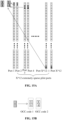
- the modulation symbol after the location information is coded and modulated may be transmitted using the symbol extension technology.
- each modulation symbol is spread to generate L symbols through a spreading sequence of L length (that is, L may represent the length of the spreading sequence).
- L may represent the length of the spreading sequence.
- each modulation symbol is spread by the spreading sequence to obtain spread symbols.
- the transmission information (that is, the transmitted data packet) has a total of N modulation symbols in the transmission if the symbol extension technology is not applied; the transmission information becomes N*L symbols when the symbol extension technology is used and the length of the spreading sequence is L. In this manner, the multi-user separation capability of the code domain can be provided. In addition, each symbol undergoes symbol extension. If the spread symbols are transmitted in the frequency domain, the modulation symbols can have better diversity effects. If transmission is a power-limited scenario and spread symbols are transmitted in the time domain, each modulation symbol may have L times of energy accumulation, and the signal-to-noise ratio may increase by L times.
- reference signals may be autonomously selected by users. Therefore, different users may select the same reference signals, that is, reference signal collision occurs. However, when overload is high, that is, when many users exist, the probability of reference signal collision is very high. Once reference signals collide, it is difficult for the base station to separate two users through the reference signals. To reduce collision and pollution of reference signals and to estimate channels, timing offset, and frequency offset, the reference signals, the sequence, and the overheads need to be doubled, and the detection complexity increases quadratically. In the sparse pilot scheme, the number of pilots is significantly increased without increasing pilot resource overheads, thus significantly reducing the probability of pilot collisions.
- the base station extracts channel information from data symbols so that the pressure of the sparse pilots can be relieved, that is, only partial, not all information of the wireless channels is required to be estimated from the sparse pilots.
- the independent multi-pilot technology refers to the inclusion of 2 or more pilots in one transmission (that is, determining W pilots; transmitting the data packet at least including the location information and the W pilots to the second communication node together; W is greater than 1), and the pilots are unrelated or independent (that is, the W pilots are independent and unrelated). In this manner, under the same pilot overheads, the probability of W independent pilots of different users colliding at the same time is much smaller than that of a single pilot.
- the base station may use an iterative receiver to decode corresponding users in each round through the pilots that have not collided, then reconstruct data and pilots of the corresponding users, and eliminate the data and pilots from the received signals. This iteration is repeated until all solvable users are solved. Since the probability of simultaneous collision between independent multi-pilots is much smaller than that of a single pilot, the transmission scheme using independent multi-pilots can support high user load in the case of competitive non-connected transmission (or contention-based scheduling-free transmission). In this embodiment, the independent multi-pilot technology and the sparse pilot technology may be combined, that is, multiple independent and unrelated sparse pilots are used to further reduce the collision of user pilots and further increase the user load.
- the frequency at which a terminal transmits the location information should not be too frequent, that is, the terminal preferably transmits the location information once at a relatively long time interval (that is, the time interval for transmitting the data packet is at least greater than a set threshold).
- the unit of the set threshold is seconds or minutes.
- the terminal autonomously reports one piece of location information every several minutes on average (or several seconds on average).
- the time interval between two transmissions of each terminal is preferably different or even random, which can be achieved by the terminal randomly determining the transmission time.
- the terminal autonomously determines a time-frequency resource for transmission. For example, the terminal autonomously determines the location of the time-frequency resource according to a random number generator.
- the structures of the random number generators of different terminals are different, or the initial seeds are different so that a certain degree of randomness can be achieved.
- the system defines or configures a common channel (that is, a transmission resource) for a terminal in a non-connected state/RRC idle state/inactive state to transmit location information on this channel.
- a broadcast signaling that is, target signaling
- the base station notifies, by the broadcast signaling, the terminal of the location of the time-frequency resource for information transmission (that is, through a target signaling, the second communication node indicates the location of the transmission resource to the first communication node).
- a terminal in a non-connected state/RRC idle state/inactive state directly transmits the data packet at least including location information of the terminal to a base station/access point (before transmission, the connected state is not required to be entered, and it is not required to apply for a resource from the base station).
- the terminal autonomously determines a transmission resource for transmission, that is, the terminal selects a time-frequency resource from the common transmission resource.
- the terminal usually autonomously determines one of the common time-frequency resources (that is, the transmission resource, including many transmission resources) defined by the system for transmitting the data packet (that is, selecting a time-frequency resource in the transmission resource; and transmitting, on the time-frequency resource, the data packet at least including the location information to the second communication node).
- the frequency of transmitting location information by the terminal is very sparse. For example, transmission is performed once every tens of seconds on average, once every few minutes, or no more than 100 times per hour on average (that is, the time interval for transmitting the location information is at least greater than a set threshold, and the set threshold is in seconds or minutes).
- the data packet at least including the location information is transmitted by the symbol extension technology.
- each modulation symbol is spread into L symbols by a spreading sequence of L length (that is, coding and modulating the data packet at least including the location information to form a modulation symbol; spreading, through a spreading sequence, the modulation symbol to obtain spread symbols; and transmitting the spread symbols to the second communication node).
- the location information includes location information of the global positioning system (GPS); location information of the BeiDou positioning system; location information of a cellular positioning system; location information of a positioning system based on a positioning tag; location information based on a wireless router (Wi-Fi router) positioning system; location information based on a Bluetooth positioning system; or location information based on an ultra-wideband positioning system.
- GPS global positioning system
- the location information based on the Wi-Fi router, the location information based on the Bluetooth positioning system, and the location information based on the ultra-wideband positioning system are more conducive to acquiring the location information of the terminal in a room.
- the independent multi-pilot is used as an example for explanation.
- the first communication node transmits, in a non-connected state, the data packet at least including location information. Since no central node exists to coordinately arrange the pilots used by different terminals, different terminals may choose the same pilot when autonomously selecting pilots from a preset pilot set with a limited number of pilots. This is the so-called problem of pilot collision. However, in a high-overload scenario, that is, in a scenario where many access terminals exist, the probability of pilot collision is high. Once pilots of different terminals collide, it is difficult for a base station to demodulate data packets of these terminals by pilots. Therefore, if the pilot collision is not handled well, the performance of transmitting location information in a non-connected state deteriorates seriously. If the related pilot scheme is still used to achieve the transmission of location information in a non-connected state, the probability of pilot collision is relatively high.
- FIG. 4 is a diagram illustrating the implementation of transmitting a data packet based on a pilot scheme according to an embodiment.
- one transmission may include a pilot/reference signal and a data packet; the pilot or reference signal may also be considered as a preamble or a demodulation reference signal (DMRS); the pilot may be located in front of the data packet (that is, payload/message in FIG. 4 ) or in the middle of the data packet.
- DMRS demodulation reference signal
- the pilot scheme has an obvious feature.
- Each transmission may include only one or one type of pilot or reference signal.
- the one or one type may mean that the pilot is composed of a sequence or multiple related sequences.
- the preamble is used for illustration.
- Transmission may include one preamble sequence or multiple associated preamble sequences.
- Such a preamble scheme may be used for timing offset and frequency offset estimation.
- FIG. 5A is a diagram illustrating the implementation of a pilot scheme according to an embodiment. As shown in FIG. 5A , the transmission may include one pilot formed by a preamble sequence.
- FIG. 5B is a diagram illustrating the implementation of another pilot scheme according to an embodiment.
- the transmission may include two preambles [P1, P2].
- OCC orthogonal cover code
- the transmission may include two preambles [P1, P2].
- Such a preamble scheme can further increase the number of preambles, but may destroy the orthogonality of the preambles.
- the DMRS is used as an example.
- the transmission may include one DMRS or multiple associated DMRSs.
- the transmission may include two DMRSs [P1, P2].
- the preamble and DMRS are available at the same time.
- the preamble and DMRS may have the preceding features.
- the preamble and DMRS are related. Generally, when a preamble is determined, the corresponding DMRS is also determined.
- one or one type of pilot/reference signal exists in the related scheme.
- the data packet at least including location information of the first communication node is transmitted to the second communication node.
- One transmission includes two or more pilots, and the pilots are independent/unassociated/unrelated.
- the pilot signal of one transmission is composed of two or more independent/unassociated/unrelated pilot sequences (that is, determining W pilots; transmitting the data packet at least including the location information and the W pilots to the second communication node together; W is greater than 1; the W pilots are independent and unrelated).
- FIG. 6A is a diagram illustrating the implementation of transmitting a data packet based on pilots according to an embodiment.
- the data packet at least including the location information of the first communication node is transmitted to the second communication node.
- the pilot signal for one transmission is composed of 2 independent/unassociated/unrelated pilot sequences (that is, preambles P1 and P2).
- FIG. 6B is another diagram illustrating the implementation of transmitting a data packet based on pilots according to an embodiment.
- the data packet at least including location information of the first communication node is transmitted to the second communication node.
- the pilot signal for one transmission is composed of W independent/unassociated/unrelated pilot sequences (that is, preambles P1, P2, ... Pw).
- the data packet including location information of the first communication node transmitted together with the pilots includes information about multiple independent and unrelated pilots.
- the data packet may include the index numbers of these pilots in a pilot set or the initial state of generated pilots.
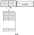
- FIG. 7 is a diagram illustrating the implementation of yet another pilot scheme according to an embodiment.
- P1 and P2 are both selected from a pilot set Z including M pilot sequences (that is, each pilot is from a pilot set including M pilots, and each pilot is determined from the pilot set according to log 2 (M) bits in the transmitted data packet).
- the pilot set Z includes z 1 , z 2 , ... z M , that is, a total of M pilot sequences.
- the first communication node selects P1 and P2 from Z.
- P1 and P2 may be determined separately by two groups of bits where each group has m bits in the data packet (that is, W pilots are determined according to one or more bits in the transmitted data packet). In this manner, once the data packet of a terminal is decoded correctly, the receiver (that is, the second communication node) can know P1 and P2 used by the terminal so that the interference of the pilot signals can be eliminated.
- P1 and P2 are determined according to 2m bits of the data packet.
- the terminal may generate 6 bits or a value of [1, 64], that is, an integer in the range of 1 to 64, from a number of bits in the data packet according to a certain rule to determine P1; the terminal may also generate 6 bits or a value of [1, 64], that is, an integer in the range of 1 to 64, from a number of bits in the data packet according to a certain rule to determine P2. In this manner, it is also not necessary to add additional information indicating the preamble sequences in the data packet, thereby saving overhead.
- P1 and P2 may be generated by additional 2m bits, but the additional 2m bits need to be put into the data packet. As a result, the data packet has an additional 2m bits, reducing the transmission efficiency.
- the system defines a sequence generation method for generating M preamble sequences.
- M preamble sequences are generated by a Zadoff-Chu sequence (ZC sequence) generation formula.
- ZC sequence Zadoff-Chu sequence
- M preamble sequences are generated by setting the two variables of the "root” value and the "cyclic shift" value in the ZC sequence formula.
- the "cyclic shift" of generating P1 is independent of the "cyclic shift" of generating P2.
- the "root" and “cyclic shift" of generating P1 are independent of the "root” and “cyclic shift” of generating P2.
- the system defines a sequence generation method for generating N preamble sequences by a shift register sequence generator.
- the N sequences are generated by setting different "initial states" of the shift register sequence generator. Then the "initial states" of P1 and P2 may be independent and unrelated.
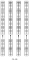
- FIG. 8 is a diagram illustrating the implementation of yet another pilot scheme according to an embodiment.
- the system defines a sequence generation method for generating M1 preamble sequences and another sequence generation method for generating M2 preamble sequences;
- the pilot set/pilot pool including M1 pilot sequences is set to Z1, and Z1 includes z 1 , z 2 , ... z M1 , with a total of M1 preamble sequences;
- the pilot set/pilot pool including M2 pilot sequences is set to Z2, and Z2 includes z 1 , z 2 , ... z M2 , with a total of M2 preamble sequences.
- P1 and P2 are generated by these two sequence generation methods respectively, but the generation of P1 and P2 is independent and unrelated (that is, at least 2 pilots of the W pilots are from different pilot sets).
- the system defines a sequence generation method for generating M1 preamble sequences by a ZC sequence formula (that is, formula1), and the system defines a sequence generation method for generating M2 preamble sequences by another ZC sequence formula (that is, formula2).
- a sequence generation method for generating M1 preamble sequences by a ZC sequence formula that is, formula1
- the system defines a sequence generation method for generating M2 preamble sequences by another ZC sequence formula (that is, formula2).
- different sequences are generated by setting two different variables of "root” and "cyclic shift" in the ZC sequence formula.
- the system defines a sequence generation method for generating M1 preamble sequences by using a shift register sequence generator 1, and the system defines a sequence generation method for generating M2 preamble sequences by a shift register sequence generator 2.
- different sequences are generated by setting different "initial states" of the shift register sequence generators.
- the system defines a sequence set 1 including M1 preamble sequences and a sequence set 2 including M2 preamble sequences.
- P1 is selected from sequence set 1.
- P2 is selected from sequence set 2.
- the index value 1 for selecting P1 from sequence set 1 and the index value 2 for selecting P2 from sequence set 2 are independent and unrelated.
- the length of the pilots in sequence set 1 including M1 preamble sequences and the length of the pilots in sequence set 2 including M2 preamble sequences may be the same or different (at least 2 pilots of the W pilots have different lengths).
- the data packet at least including location information of the first communication node is transmitted to the second communication node.
- W pilots are independent/unassociated/unrelated.
- the W pilots may be one of the following: W preamble sequences transmitted in a physical random-access channel (PRACH) defined by the long-term evolution (LTE) standard; W PRACH preamble sequences defined by the New Radio (NR) standard; W DMRS sequences defined by the LTE standard; W DMRS sequences defined by the NR standard; W maximum length shift register (MLSR) sequences; W discrete Fourier transform DFT) sequences; or W Walsh-Hadamard sequences.
- PRACH physical random-access channel
- LTE long-term evolution
- NR New Radio
- W DMRS sequences defined by the LTE standard
- W DMRS sequences defined by the NR standard W maximum length shift register (MLSR) sequences
- W discrete Fourier transform DFT discrete Fourier transform DFT
- the receiver may perform channel estimation using the second non-colliding preamble sequences to demodulate the data packets of terminal 1 and terminal 2.
- the independent multi-pilot technology means that two or more pilots are included in one transmission, and the pilots are independent, unrelated, and unassociated. In this manner, under the same pilot overheads, the probability of simultaneous collision of independent multi-pilots of different terminals is much smaller than that of a single pilot.
- the base station may use an iterative receiver to decode data packets of corresponding terminals in each round through non-colliding pilots, then reconstruct data and pilots of the corresponding terminals, and eliminate the data and pilots from the received signals. This iteration is repeated until all the decodable data packets of the terminals are decoded. Since the probability of simultaneous collision between independent multi-pilots is much smaller than that of a single pilot, the transmission scheme using independent multi-pilots can support high user load in the case of non-connected transmission.
- the sparse pilot is used as an example for description.
- each reference signal needs to occupy sufficient resources, and reference signals need to be throughout the entire transmission bandwidth and time.
- each reference signal cannot be too sparse in the entire transmission bandwidth and time, and a specific density is required so that the wireless multi-path channel (that is, the frequency-selective channel) in the entire transmission bandwidth and the frequency offset in the transmission time can be estimated. Therefore, to ensure the transmission performance in a non-connected state and still use the relevant pilot scheme, the overheads occupied by pilots increase exponentially, and the detection complexity also increases significantly.
- a demodulation reference signal (DMRS) set is defined, including 12 reference signals.
- a demodulation reference signal may also be referred to as a demodulation reference signal port (DMRS port), that is, a set of 12 DMRS ports is defined.
- DMRS port demodulation reference signal port
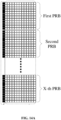
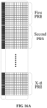
- FIG. 10A is a diagram illustrating the implementation of defining a physical resource block according to an embodiment.
- a defined physical resource block includes 14 orthogonal frequency-division multiplexing (OFDM) (or Discrete Fourier Transform-Spread-Orthogonal Frequency-Division Multiplexing (DFT-S-OFDM) or single-carrier frequency-division multiple access (SC-FDMA)) symbols in the time domain and 12 subcarriers in the frequency domain.
- OFDM orthogonal frequency-division multiplexing
- DFT-S-OFDM Discrete Fourier Transform-Spread-Orthogonal Frequency-Division Multiplexing
- SC-FDMA single-carrier frequency-division multiple access
- This type of DMRS uses the first two OFDM symbols to carry the demodulation reference signal, that is, the first two OFDM symbols are used as a DMRS area.
- resource overheads occupied by the DMRS are 1/7.
- the area other than the DMRS area is a data symbol area.
- FIG. 10B is a diagram illustrating the implementation of defining demodulation reference signals according to an embodiment.
- demodulation reference signals may be divided into three groups according to the position of the occupied resource units (REs); the non-zero symbols (non-zero signals or useful signals) (that is, the symbols are non-zero values) of the first group of the DMRSs are carried on the REs of the pattern shown in FIG. 10A , and the first group of 4 DMRS ports are distinguished by OCC codes; the non-zero symbols of the second group of the DMRSs are carried on the REs of the pattern shown in FIG.
- REs occupied resource units
- Each demodulation reference signal takes a value of 0 on the RE of the blank unfilled pattern as shown in FIG. 10B , or no signal exists. It can be seen that for each demodulation reference signal, not all REs in the demodulation reference signal area have signals. However, for a terminal, as long as the terminal uses a certain reference signal/ a certain reference signal port, the terminal usually cannot use these REs to transmit data although the reference signal port has no signal on some REs in the DMRS area. From this perspective, the resource overheads occupied by a reference signal/a reference signal port are also 1/7.
- Non-zero symbols of each group of demodulation reference signals are carried on the same resource element (RE), and different reference signals can only be distinguished by non-zero symbols of different values.
- different reference signal ports can be distinguished by the time domain OCC code and the frequency domain OCC code.
- FIG. 10C is another diagram illustrating the implementation of defining demodulation reference signals according to an embodiment. As shown in FIG. 10C , four demodulation reference signals in the first group in FIG. 10B are used as an example.
- demodulation reference signal ports are separated by jointly using long-two (that is, the length is 2) OCC codes of [1, 1] and [1, -1] in the time domain and long-two (that is, the length is 2) OCC codes of [1, 1] and [1, -1] in the frequency domain. That is, in each group of DMRS ports, different DMRS ports are generated by carrying different OCC codes on patterned REs. The situation of the four reference signals in the second and third groups in FIG. 10B is similar. In this manner, a total of 12 demodulation reference signals of the defined demodulation reference signal (DMRS) set, that is, 12 demodulation reference signal ports, can be obtained.
- DMRS defined demodulation reference signal
- FIG. 11A is a diagram illustrating the implementation of defining demodulation reference signals using an OCC according to an embodiment. As shown in FIG. 11A , for four demodulation reference signals in the first group in FIG. 10B , four demodulation reference signal ports are separated by jointly using long-two OCC codes of [1, 1] and [1, -1] in the time domain and long-two OCC codes of [1, 1] and [1, -1] in the frequency domain.
- FIG. 11B is another diagram illustrating the implementation of defining demodulation reference signals using an OCC according to an embodiment. As shown in FIG. 11B , for four demodulation reference signals in the second group in FIG. 10B , four demodulation reference signal ports are separated by jointly using long-two OCC codes of [1, 1] and [1, -1] in the time domain and long-two OCC codes of [1, 1] and [1, -1] in the frequency domain.
- FIG. 11C is yet another diagram illustrating the implementation of defining demodulation reference signals using an OCC according to an embodiment.
- 8 represents a first reference signal unit
- 9 represents a second reference signal unit; for four demodulation reference signals in the third group in FIG. 10B , four demodulation reference signal ports are separated by jointly using long-two OCC codes of [1, 1] and [1, -1] in the time domain and long-two OCC codes of [1, 1] and [1, -1] in the frequency domain.
- a reference signal carried on several adjacent resource elements (REs) in the time domain and frequency domains may be referred to as a reference signal element (RSE).
- RSE reference signal element
- FIGS. 10A to 10C and 11A to 11C a reference signal carried on four consecutive REs in the time and frequency domains are referred to as an RSE.
- the reference signal on the "grid" filled with a pattern is an RSE.
- an RSE From the perspective of the channel estimation function, in addition to the characteristic of being composed of adjacent resource elements in the time and frequency domains, an RSE has another characteristic, that is, when applying a reference signal for channel estimation, each RSE may estimate a channel value.
- each reference signal has 2 RSEs within 1 PRB bandwidth, so the channel value at 2 points within a PRB bandwidth (that is, within a bandwidth of 12 subcarriers) can be estimated.
- the channel values of 12 subcarriers within a PRB bandwidth need to be obtained by interpolation of estimation values of these reference signal units.
- FIG. 12A is a diagram illustrating the implementation of transmission based on a PRB according to an embodiment.
- the 12 demodulation reference signals (or 12 demodulation reference signal ports) of this reference signal set are shown in FIG. 12A , and each reference signal has 2*X RSEs.
- the channel values at 2*X equally spaced locations within the entire transmission bandwidth can be estimated, and then the channel values of all 12*X subcarriers within the transmission bandwidth are obtained by interpolation.
- the 12 DMRSs can be divided into three groups according to the occupied positions of REs.
- FIG. 12B is yet another diagram illustrating the implementation of defining demodulation reference signals according to an embodiment. As shown in FIG. 12B , the four demodulation reference signals of the first group are distinguished by the OCC code.
- FIG. 12C is yet another diagram illustrating the implementation of defining demodulation reference signals according to an embodiment. As shown in FIG. 12C , the four demodulation reference signals of the second group are distinguished by the OCC code.
- FIG. 12D is yet another diagram illustrating the implementation of defining demodulation reference signals according to an embodiment. As shown in FIG. 12D , the four demodulation reference signals of the third group are distinguished by the OCC code.
- the demodulation reference signal (or pilot) occupies a relatively large amount of resources, or the demodulation reference signal needs a certain density in the entire transmission bandwidth and cannot be too sparse.
- the density of this demodulation reference signal in the entire transmission bandwidth is 2 reference signals per PRB or 2 reference signal units (RSE) per PRB.
- the overheads of the reference signals are 1/7, that is, 1/7 resources paid by the system can only design 12 demodulation reference signals.
- the collision probability of any two terminals autonomously selecting reference signals is 1/12, which is still very high. Therefore, the demodulation reference signal severely limits the number of terminals transmitting data in the non-connected transmission state.
- the resources occupied by each reference signal need to be further increased, or the density of each reference signal in the transmission signal needs to be further encrypted. For example, repetition is performed once in the timing domain to estimate the frequency offset. In this manner, the resources occupied by the reference signal double, that is, the overheads are 2/7. That is, the system pays 2/7 of the resources and can only design 12 demodulation reference signals to estimate the frequency-selective channel and frequency offset. If the system further needs to cope with a certain timing offset, the resources occupied by the reference signal need to be further increased. For example, 3/7 or even 4/7 of the overheads are required to design 12 demodulation reference signals. With such large overheads, only a small number of reference signal sets (or a small number of reference signal ports) can be obtained, and the probability of collision in the non-connected state is very high.
- each demodulation reference signal has three reference signal units (for example, 3 grids exists in a figurative sense) in each PRB bandwidth. In this manner, each PRB may have 3 estimated values, X PRBs have 3*X estimated values, and then the channels of all subcarriers of X PRBs are obtained by linear interpolation.
- This reference signal still accounts for 1/7 overheads of the transmission resource, but only 8 demodulation reference signals (8 demodulation reference signal ports) can be separated, less than that of the definition above. It can be seen that the channel estimation capability is usually inversely proportional to the number of reference signals.
- reference signals are needed to estimate the frequency selection channel, timing offset, and frequency offset of the entire transmission channel and are also needed to identify terminal users, so reference signals need to occupy more time-frequency resources to complete such heavy tasks. This leads to a serious shortage of reference signals under certain resources.
- the number of terminals supporting transmission in a non-connected state is limited by the number of reference signals.
- the main starting point of the present application is to greatly reduce the tasks of reference signals, so the resources occupied by each reference signal can be minimized, or each reference signal can be the sparsest.
- the number of reference signals can be maximized, and finally, both pre-configured scheduling-free and contention-based scheduling-free can support more terminals.
- FIG. 13A is a diagram of a BPSK symbol according to an embodiment. As shown in FIG. 13A , the constellation diagram of a binary phase shift keying (BPSK) symbol transmitted by the terminal may be considered as a standard BPSK constellation diagram.
- BPSK binary phase shift keying
- FIG. 13B is another diagram of a BPSK symbol according to an embodiment.
- FIG. 13C is yet another diagram of a BPSK symbol according to an embodiment.
- the BPSK symbol is no longer the standard BPSK constellation diagram shown in FIG13A but is imposed a weighting coefficient by the wireless channel, that is, a rotation plus a scaling change and the receiver's additive white Gaussian noise (AWGN) results in symbol scatter points.
- FIG. 13B shows the scatter points corresponding to the symbols after channel weighting.
- the channel weighting can be estimated using the geometric shape of the symbol scatter points.
- the constellation diagram of a low-order modulation signal such as BPSK after rotation and scaling (that is, channel weighting) still has strong geometric characteristics, so channel estimation and equalization can use the geometric characteristics of this constellation diagram to estimate the rotation amount and scaling amount, and then the constellation diagram can be reversely rotated back so that the equalization is completed. That is, the symbol scatter points after signal equalization are obtained, as shown in FIG. 13C .
- the scatter points corresponding to the symbol received by the base station can still be seen as two groups of separated scatter points. The base station only needs to add up the circular scatter points and the triangular scatter points separately to obtain two scatter point centers.
- the base station rotates the scatter point center corresponding to the triangular scatter points by 180° and adds up the scatter point center corresponding to the circular scatter points to obtain the channel weighting expressed in complex form on the final BPSK symbol and also obtain the rotation amount and scaling amount.
- the angle of the complex number is the rotation amount
- the modulus of the complex number is the scaling amount.
- the task of the reference signal is much smaller than that of the related scheme, so each reference signal occupies much fewer resources than that of the related solution.
- the number of reference signals in the present application is much more than that of the related solution.
- the base station when the base station has multiple receiving antennas, such as R receiving antennas, the base station can theoretically provide a very powerful spatial capability to improve the performance of multi-terminal access.
- the receiver uses the spatially merged data symbol s k to estimate the channel of the entire transmission bandwidth experienced by the signal of terminal k and to estimate the timing offset and frequency offset. Then, the spatially merged data symbol s k is compensated for the timing offset and frequency offset. Finally, the data symbol compensated for the timing offset and frequency offset is demodulated and decoded.
- FIG. 14A is a diagram illustrating the implementation of defining a reference signal according to an embodiment.
- the reference signal proposed by the present application occupies one OFDM symbol.
- One transmission includes X PRB time-frequency resources.
- One physical resource block (PRB) includes 14 OFDM (DFT-S-OFDM or SC-FDMA) symbols in the time domain and 12 subcarriers in the frequency domain.
- the first OFDM symbol is used to carry a demodulation reference signal, that is, the first OFDM symbol is used as the extremely sparse pilot area, and 1/14 of the resources are used to transmit the reference signal. That is, 12*X REs are used to transmit the reference signal.
- the area other than the extremely sparse pilot area is the data symbol area.
- FIG. 14B is another diagram illustrating the implementation of defining a reference signal according to an embodiment. As shown in FIG. 14B , each reference signal defined by the system has a non-zero symbol (a non-zero signal or a useful signal) on only one RE, and no signal exists in other places (or the value of other places is 0).
- the reference signal area occupying 1/14 of the overheads can be divided into 12*X reference signals in total.
- FIG. 15A is yet another diagram illustrating the implementation of defining a reference signal according to an embodiment.
- each reference signal defined by the system has non-zero symbols (non-zero signals or useful signals) only on 2 REs. Every 2 REs are divided into 2 reference signals through a length-two OCC, and no signal exists in other places (or the value of other places is 0).
- the reference signal area occupying 1/14 of the overheads can also be divided into 12*X reference signals in total.
- the number of extremely sparse pilots is proportional to the number of PRBs.
- FIG. 15B is a diagram illustrating the implementation of generating DMRS ports according to an embodiment. As shown in FIG. 15B , different OCC codes (such as OCC code 1 and OCC code 2) are carried on two patterned REs to generate different DMRS ports.
- OCC codes such as OCC code 1 and OCC code 2
- FIG. 16A is yet another diagram illustrating the implementation of defining a reference signal according to an embodiment. As shown in FIG. 16A , the reference signal defined by the system occupies 2 OFDM symbols.
- FIG. 16B is yet another diagram illustrating the implementation of defining a reference signal according to an embodiment. As shown in FIG. 16B , each reference signal defined by the system has non-zero symbols (non-zero signals or useful signals) only on a group of adjacent 4 REs, but 4 reference signals exist and reuse a group of adjacent 4 REs. The four reference signals reusing the same group of four adjacent REs are distinguished by OCC codes.
- the reference signal area that accounts for 1/7 of the overheads can be divided into a total of 24*X reference signals.
- the numerical values shown in the embodiment of the present application are only exemplary descriptions and are not specifically limited. The values may be adjusted adaptively according to actual situations. It can be learned that sparse pilots actually indicate that each pilot in a pilot set has very few non-zero elements. For example, only 1-4 non-zero elements exist. This can significantly increase the number of pilots without increasing overheads of pilot resources, thus significantly reducing the probability of pilot collisions.
- the base station estimates part of the information about the wireless channel from the sparse pilots, but does not need to estimate all the information about the wireless channel from the sparse pilots. The base station further extracts channel information from the data symbols and then uses this channel information to complete the equalization of the data symbols.
- pilots are only used for spatial merging, but not for channel equalization, and the pilots can be considered as spatial merging reference signals.
- the extremely sparse reference signals shown in FIG. 14A , FIG. 14B , FIG. 15A, and FIG. 15B are all located 1 or 2 symbols in front of the transmission resource, the present application does not limit the location of the extremely sparse reference signals.
- the location of the extremely sparse reference signals may also be located in the middle symbol of the transmission resource.
- the preceding independent multi-pilot technology and extremely sparse pilot technology may be combined to further reduce collisions of terminal pilots and further improve the terminal load.
- FIG. 17 is a diagram illustrating the implementation of an information transmission method according to an embodiment.
- transmission of the data packet including location information includes W extremely sparse reference signals
- the data packet includes information about the W extremely sparse reference signals, such as the index numbers of the W extremely sparse reference signals.
- FIG. 18 is a diagram illustrating the structure of an information transmission apparatus according to an embodiment. As shown in FIG. 18 , the information transmission apparatus may be configured in a first communication node and includes an acquisition module 310 and a transmission module 320.
- the acquisition module 310 is configured to acquire location information of the first communication node.
- the transmission module 320 is configured to transmit, in a non-connected state, a data packet at least including the location information to a second communication node.
- the acquired location information of the first communication node is transmitted to the corresponding second communication node in the non-connected state so that the increase in power consumption caused by repeated interaction in establishing a connection with the second communication node can be avoided.
- the apparatus also includes a signaling acquisition module and a resource determination module.
- the signaling acquisition module is configured to acquire a target signaling.
- the resource determination module is configured to determine, based on the target signaling, a transmission resource configured or defined by the second communication node, where the transmission resource is used by the first communication node in a non-connected state to transmit the data packet at least including location information.
- the transmission module 320 includes a selection unit and a transmission unit.
- the selection unit is configured to select a time-frequency resource in the transmission resource.
- the transmission unit is configured to transmit the data packet at least including the location information to the second communication node on the time-frequency resource.
- the transmission module 320 includes a first determination unit and a first transmission unit.
- the first determination unit is configured to determine W pilots.
- the first transmission unit is configured to transmit the data packet at least including the location information and the W pilots to the second communication node together; where W is greater than 1.
- the W pilots are independent and unrelated.
- the W pilots are determined according to information in the transmitted data packet.
- the W pilots are determined according to one or more bits in the transmitted data packet.
- each pilot is from a pilot set including M pilots, and each pilot is determined from the pilot set according to log 2 (M) bits in the transmitted data packet.
- At least two pilots of the W pilots are from different pilot sets.
- At least two pilots of the W pilots have different lengths.
- only U symbols in each pilot of the W pilots are non-zero values, where U is greater than 0 and less than 5.
- the value of W is 2.
- the transmission module 320 includes a second determination unit and a second transmission unit.
- the second determination unit is configured to determine a pilot, where only U symbols in the pilot are non-zero values, and U is greater than 0 and less than 5.
- the second transmission unit is configured to transmit the data packet at least including the location information and the 1 pilot to the second communication node together.
- the time interval for transmitting the data packet is at least greater than a set threshold.
- the set threshold is in seconds or minutes.
- the transmission module 320 includes a modulation unit and a third transmission unit.
- the modulation unit is configured to spread, through a spreading sequence, a modulation symbol formed by coding and modulating the data packet at least including location information to obtain spread symbols.
- the third transmission unit is configured to transmit the spread symbols to the second communication node.
- the spreading sequence is determined according to information in the transmitted data packet.
- the spreading sequence is from a set including V spreading sequences, and the spreading sequence is determined from the set including V spreading sequences by log 2 (V) bits in the transmitted data packet.
- the location information includes one or more of the following: location information of a global positioning system; location information of the BeiDou positioning system; location information of a cellular positioning system; location information of a positioning system based on a positioning tag; location information based on a wireless router positioning system; location information based on a Bluetooth positioning system; or location information based on an ultra-wideband positioning system.
- the data packet including location information includes information related to the identity of the first communication node.
- the data packet including location information does not include information related to the identity of the first communication node.
- the information transmission apparatus provided in this embodiment and the information transmission method provided in the preceding embodiments belong to the same inventive concept. For technical details not described in detail in this embodiment, reference may be made to any one of the preceding embodiments.
- the embodiment has the same beneficial effects as the applied information transmission method.
- FIG. 19 is a diagram illustrating the structure of an information transmission apparatus according to an embodiment.
- the information transmission apparatus may be configured in a second communication node and includes a determination module 410 and an indication module 420.
- the determination module 410 is configured to determine a transmission resource.
- the indication module 420 is configured to indicate, through a target signaling, the location of the transmission resource to a first communication node, where the transmission resource is used by the first communication node in a non-connected state to transmit a data packet at least including location information.
- a transmission resource is determined, and then the transmission resource is transmitted to the first communication node by defining a target signaling.
- the location of the transmission resource can be indicated to the first communication node so that the first communication node can transmit, in a non-connected state, a data packet at least including location information based on the transmission resource. In this manner, increased power consumption caused by the first communication node repeatedly interacting with the second communication node to establish a connection for transmitting the data packet is avoided.
- the determination module 410 includes a definition unit.
- the definition unit is configured to define or configure the transmission resource.
- the apparatus also includes a receiving module.
- the receiving module is configured to receive the data packet transmitted by the first communication node and at least including the location information.
- the data packet is transmitted on the transmission resource.
- the receiving module includes a first receiving unit.
- the first receiving unit is configured to receive the data packet transmitted by the first communication node and at least including the location information and W pilots transmitted together with the data packet, where W is greater than 1.
- the W pilots are independent and unrelated.
- the W pilots are determined according to information in the transmitted data packet.
- the W pilots are determined according to one or more bits in the transmitted data packet.
- each pilot is from a pilot set including M pilots, and each pilot is determined from the pilot set according to log 2 (M) bits in the transmitted data packet.
- At least two pilots of the W pilots are from different pilot sets.
- At least two pilots of the W pilots have different lengths.
- only U symbols in each pilot of the W pilots are non-zero values, where U is greater than 0 and less than 5.
- the value of W is 2.
- the time interval for transmitting the data packet is at least greater than a set threshold.
- the set threshold is in seconds or minutes.
- the apparatus also includes a second receiving unit.
- the second receiving unit is configured to receive spread symbols transmitted by the first communication node; the spread symbols are symbols obtained by spreading a modulation symbol through a spreading sequence, and the modulation symbol is a symbol obtained by coding and modulating the data packet at least including the location information.
- the spreading sequence is determined according to information in the transmitted data packet.
- the spreading sequence is from a set including V spreading sequences, and the spreading sequence is determined from the set including V spreading sequences by log 2 (V) bits in the transmitted data packet.
- the location information includes one or more of the following: location information of a global positioning system; location information of the BeiDou positioning system; location information of a cellular positioning system; location information of a positioning system based on a positioning tag; location information based on a wireless router; location information based on a Bluetooth positioning system; or location information based on an ultra-wideband positioning system.
- the receiving module includes a third receiving unit.
- the third receiving unit is configured to receive the data packet transmitted by the first communication node and at least including the location information and 1 pilot transmitted together with the data packet.
- the data packet including location information includes information related to the identity of the first communication node.
- the data packet including location information does not include information related to the identity of the first communication node.
- the information transmission apparatus provided in this embodiment and the information transmission method provided in the preceding embodiments belong to the same inventive concept. For technical details not described in detail in this embodiment, reference may be made to any one of the preceding embodiments.
- the embodiment has the same beneficial effects as the applied information transmission method.
- FIG. 20 is a diagram illustrating the structure of hardware of a communication node according to an embodiment.
- the communication node provided by this application includes a storage apparatus 520, a processor 510, and a computer program stored on the storage apparatus and runnable on the processor.
- the processor 510 when executing the program, implements the preceding information transmission method.
- the communication node may also include the storage apparatus 520.
- One or more processors 510 may be provided in the communication node, and one processor 510 is used as an example in FIG. 20 .
- the storage apparatus 520 is configured to store one or more programs that, when executed by the one or more processors 510, cause the one or more processors 510 to implement the information transmission method in embodiments of the present application.
- the communication node also includes a communication apparatus 530, an input apparatus 540, and an output apparatus 550.
- the one or more processors 510, the storage apparatus 520, the communication apparatus 530, the input apparatus 540, and the output apparatus 550 in the communication node may be connected via a bus or other means, with connection via the bus as an example in FIG. 20 .
- the input apparatus 540 may be configured to receive input digital or character information and generate key signal input related to user settings and function control of the communication node.
- the output apparatus 550 may include a display device, for example, a display screen.
- the communication apparatus 530 may include a receiver and a sender.
- the communication apparatus 530 is configured to perform information transceiving and communication under the control of the one or more processors 510.
- the storage apparatus 520 may be configured to store software programs, computer-executable programs, and modules, such as program instructions/modules (for example, the acquisition module 310 and the transmission module 320 in the information transmission apparatus; or the determination module 410 and the indication module 420 in the information transmission apparatus) corresponding to the information transmission method according to embodiments of the present application.
- the storage apparatus 520 may include a program storage region and a data storage region, where the program storage region may store an operating system and an application program required by at least one function while the data storage region may store data created depending on use of the communication node.
- the storage apparatus 520 may include a high-speed random-access memory and may also include a non-volatile memory, such as at least one magnetic disk memory, a flash memory, or another non-volatile solid-state memory.
- the storage apparatus 520 may also include memories which are remotely disposed with respect to the processor 510. These remote memories may be connected to the communication node via a network. Examples of the preceding network include but are not limited to, the Internet, an intranet, a local area network, a mobile communication network, and a combination thereof.
- An embodiment of the present application provides a storage medium.
- the storage medium stores a computer program that, when executed by a processor, causes the processor to perform the information transmission method according to any embodiment of the present application.
- the information transmission method is applied to a first communication node and includes the following: location information of the first communication node is acquired. In a non-connected state, a data packet at least including the location information is transmitted to a second communication node.
- the information transmission method is applied to a second communication node and includes the following: a transmission resource is determined. Through a target signaling, the location of the transmission resource is indicated to a first communication node, where the transmission resource is used by the first communication node in a non-connected state to transmit a data packet at least including location information.
- a computer storage medium in this embodiment of the present application may adopt any combination of one or more computer-readable media.
- the computer-readable medium may be a computer-readable signal medium or a computer-readable storage medium.
- the computer-readable storage medium may be, for example, but is not limited to, an electrical, magnetic, optical, electromagnetic, infrared, or semiconductor system, apparatus, or device, or any combination thereof.
- Examples (a non-exhaustive list) of the computer-readable storage medium include an electrical connection having one or more wires, a portable computer magnetic disk, a hard disk, a random-access memory (RAM), a read-only memory (ROM), an erasable programmable read-only memory (EPROM), a flash memory, an optical fiber, a portable compact disc read-only memory (CD-ROM), an optical memory device, a magnetic memory device, or any suitable combination thereof.
- the computer-readable storage medium may be any tangible medium including or storing a program. The program may be used by or used in conjunction with an instruction execution system, apparatus, or device.
- the computer-readable signal medium may include a data signal propagated in a baseband or as part of a carrier.
- the data signal carries computer-readable program codes.
- the data signal propagated in this manner may be in multiple forms and includes, but is not limited to, an electromagnetic signal, an optical signal, or any suitable combination thereof.
- the computer-readable signal medium may also be any computer-readable medium other than the computer-readable storage medium.
- the computer-readable medium may send, propagate, or transmit a program used by or used in conjunction with an instruction execution system, apparatus, or device.
- the program codes included on the computer-readable medium may be transmitted on any suitable medium including, but not limited to, a wireless medium, a wire, an optical cable, a radio frequency (RF), or any suitable combination thereof.
- a wireless medium including, but not limited to, a wireless medium, a wire, an optical cable, a radio frequency (RF), or any suitable combination thereof.
- RF radio frequency
- Computer program codes for performing the operations of the present application may be written in one or more programming languages or a combination of multiple programming languages.
- the programming languages include object-oriented programming languages such as Java, Smalltalk, and C++ and may also include conventional procedural programming languages such as "C" or similar programming languages.
- the program codes may be executed entirely on a user computer, partly on a user computer, as a stand-alone software package, partly on a user computer and partly on a remote computer, or entirely on a remote computer or a server.
- the remote computer may be connected to the user computer via any type of network including a local area network (LAN) or a wide area network (WAN) or may be connected to an external computer (for example, via the Internet by an Internet service provider).
- LAN local area network
- WAN wide area network
- Internet service provider for example, via the Internet by an Internet service provider
- user terminal encompasses any suitable type of wireless user device, for example, a mobile phone, a portable data processing apparatus, a portable web browser, or a vehicle-mounted mobile station.
- various embodiments of the present application may be implemented in hardware or special-purpose circuits, software, logic, or any combination thereof.
- some aspects may be implemented in hardware while other aspects may be implemented in firmware or software executable by a controller, a microprocessor, or another calculation apparatus, though the present application is not limited thereto.
- Embodiments of the present application may be implemented through the execution of computer program instructions by a data processor of a mobile apparatus, for example, implemented in a processor entity, by hardware, or by a combination of software and hardware.
- the computer program instructions may be assembly instructions, instruction set architecture (ISA) instructions, machine instructions, machine-related instructions, microcodes, firmware instructions, state setting data, or source or object codes written in any combination of one or more programming languages.
- ISA instruction set architecture
- a block diagram of any logic flow among the drawings of the present application may represent program procedures, may represent interconnected logic circuits, modules, and functions, or may represent a combination of program procedures with logic circuits, modules, and functions.
- Computer programs may be stored in a memory.
- the memory may be of any type suitable for a local technical environment and may be implemented using any suitable data storage technology, such as, but not limited to, a read-only memory (ROM), a random-access memory (RAM), and an optical memory apparatus and system (a digital video disc (DVD) or a compact disk (CD)).
- Computer-readable medium may include a non-transitory storage medium.
- the data processor may be of any type suitable for a local technical environment, such as, but not limited to, a general-purpose computer, a special-purpose computer, a microprocessor, a digital signal processor (DSP), an application-specific integrated circuit (ASIC), a field-programmable gate array (FPGA), and a processor based on a multi-core processor architecture.
- a general-purpose computer such as, but not limited to, a general-purpose computer, a special-purpose computer, a microprocessor, a digital signal processor (DSP), an application-specific integrated circuit (ASIC), a field-programmable gate array (FPGA), and a processor based on a multi-core processor architecture.
- DSP digital signal processor
- ASIC application-specific integrated circuit
- FPGA field-programmable gate array
Landscapes
- Engineering & Computer Science (AREA)
- Signal Processing (AREA)
- Computer Networks & Wireless Communication (AREA)
- Mobile Radio Communication Systems (AREA)
Applications Claiming Priority (2)
| Application Number | Priority Date | Filing Date | Title |
|---|---|---|---|
| CN202210647872.1A CN117241350A (zh) | 2022-06-08 | 2022-06-08 | 一种信息传输方法、通信节点及存储介质 |
| PCT/CN2023/098836 WO2023236985A1 (zh) | 2022-06-08 | 2023-06-07 | 一种信息传输方法、通信节点及存储介质 |
Publications (1)
| Publication Number | Publication Date |
|---|---|
| EP4529319A1 true EP4529319A1 (de) | 2025-03-26 |
Family
ID=89081335
Family Applications (1)
| Application Number | Title | Priority Date | Filing Date |
|---|---|---|---|
| EP23819150.6A Pending EP4529319A1 (de) | 2022-06-08 | 2023-06-07 | Informationsübertragungsverfahren, kommunikationsknoten und speichermedium |
Country Status (4)
| Country | Link |
|---|---|
| US (1) | US20250365786A1 (de) |
| EP (1) | EP4529319A1 (de) |
| CN (1) | CN117241350A (de) |
| WO (1) | WO2023236985A1 (de) |
Families Citing this family (1)
| Publication number | Priority date | Publication date | Assignee | Title |
|---|---|---|---|---|
| CN120111523A (zh) * | 2024-08-16 | 2025-06-06 | 中兴通讯股份有限公司 | 一种通信方法、装置、存储介质及程序产品 |
Family Cites Families (6)
| Publication number | Priority date | Publication date | Assignee | Title |
|---|---|---|---|---|
| CN110856276B (zh) * | 2019-11-15 | 2022-03-22 | 展讯通信(上海)有限公司 | 非连接态ue的数据传输、接收方法及装置、终端、基站 |
| CN113259071B (zh) * | 2020-02-07 | 2022-12-13 | 大唐移动通信设备有限公司 | 信号传输方法及装置 |
| CN111901855A (zh) * | 2020-07-22 | 2020-11-06 | 中兴通讯股份有限公司 | 数据传输方法、装置、设备和存储介质 |
| CN114285532A (zh) * | 2020-09-27 | 2022-04-05 | 展讯半导体(南京)有限公司 | 数据传输方法及装置、存储介质、终端、基站 |
| WO2022061872A1 (zh) * | 2020-09-28 | 2022-03-31 | Oppo广东移动通信有限公司 | 一种小数据传输方法及装置、终端设备 |
| CN115777224B (zh) * | 2020-09-30 | 2025-08-01 | Oppo广东移动通信有限公司 | 数据传输方法、装置、设备及存储介质 |
-
2022
- 2022-06-08 CN CN202210647872.1A patent/CN117241350A/zh active Pending
-
2023
- 2023-06-07 EP EP23819150.6A patent/EP4529319A1/de active Pending
- 2023-06-07 WO PCT/CN2023/098836 patent/WO2023236985A1/zh not_active Ceased
- 2023-06-07 US US18/872,456 patent/US20250365786A1/en active Pending
Also Published As
| Publication number | Publication date |
|---|---|
| US20250365786A1 (en) | 2025-11-27 |
| CN117241350A (zh) | 2023-12-15 |
| WO2023236985A1 (zh) | 2023-12-14 |
Similar Documents
| Publication | Publication Date | Title |
|---|---|---|
| EP3975651B1 (de) | Verfahren, benutzergerät und basisstation für den zufallszugriff in einem drahtlosen kommunikationssystem | |
| EP3888409B1 (de) | Verfahren und vorrichtung zum senden und empfangen eines signals in einem drahtloskommunikationssystem | |
| EP4529286A1 (de) | Informationsübertragungsverfahren, kommunikationsknoten und speichermedium | |
| US10736152B2 (en) | Method for resolving resource collision in V2X communication environment and mobile device therefor | |
| US20240292464A1 (en) | Method and device for transmitting random access signal, and computer readable medium | |
| CN110086582A (zh) | 一种信道测量方法和系统、第一通信节点及第二通信节点 | |
| US11196474B2 (en) | Methods for multi-antenna transmission in vehicular communications | |
| EP4529319A1 (de) | Informationsübertragungsverfahren, kommunikationsknoten und speichermedium | |
| Tseng et al. | A cross-layer scheme for solving hidden device problem in IEEE 802.15. 4 wireless sensor networks | |
| CN117956621A (zh) | 信号检测方法、信号发送方法、装置及存储介质 | |
| EP4525489A1 (de) | Informationsübertragungsverfahren und -vorrichtung | |
| EP4525525A1 (de) | Informationsübertragungsverfahren und -vorrichtung sowie speichermedium | |
| Mostafa et al. | Aggregate preamble sequence design for massive machine-type communications in 5G networks | |
| US20250274233A1 (en) | Orthogonal time domain reference signal transmission | |
| US9960934B2 (en) | Channel estimation for FBMC modulation | |
| CN117955614A (zh) | 参考信号的配置方法、通信装置及存储介质 | |
| Watanabe et al. | Poster: A scheduling method for V2V networks using successive interference cancellation | |
| CN118945023A (zh) | 一种通信方法及装置 | |
| Zhang et al. | Hybrid ORA and NORA schemes for machine‐to‐machine communication in long‐term evolution networks | |
| Al-Imari | A method for resolving users' collision in random access schemes in 5G systems | |
| CN103326964A (zh) | 一种实现数据解调的方法、装置和系统 | |
| Hadjadj‐Aoul et al. | Using Reinforcement Learning to Manage Massive Access in NB‐IoT Networks | |
| WO2025163628A1 (en) | On-demand sib1 transmission | |
| Roy | SURVEY OF THE INTERFERENCE SOURCES IN SEVERAL IOT TECHNOLOGIES | |
| CN121940856A (zh) | 一种通信方法及装置 |
Legal Events
| Date | Code | Title | Description |
|---|---|---|---|
| STAA | Information on the status of an ep patent application or granted ep patent |
Free format text: STATUS: THE INTERNATIONAL PUBLICATION HAS BEEN MADE |
|
| PUAI | Public reference made under article 153(3) epc to a published international application that has entered the european phase |
Free format text: ORIGINAL CODE: 0009012 |
|
| STAA | Information on the status of an ep patent application or granted ep patent |
Free format text: STATUS: REQUEST FOR EXAMINATION WAS MADE |
|
| 17P | Request for examination filed |
Effective date: 20241219 |
|
| AK | Designated contracting states |
Kind code of ref document: A1 Designated state(s): AL AT BE BG CH CY CZ DE DK EE ES FI FR GB GR HR HU IE IS IT LI LT LU LV MC ME MK MT NL NO PL PT RO RS SE SI SK SM TR |
|
| DAV | Request for validation of the european patent (deleted) | ||
| DAX | Request for extension of the european patent (deleted) |