EP4529247A2 - Verbesserter adressenwechsel für drahtlose netzwerksysteme - Google Patents
Verbesserter adressenwechsel für drahtlose netzwerksysteme Download PDFInfo
- Publication number
- EP4529247A2 EP4529247A2 EP25156875.4A EP25156875A EP4529247A2 EP 4529247 A2 EP4529247 A2 EP 4529247A2 EP 25156875 A EP25156875 A EP 25156875A EP 4529247 A2 EP4529247 A2 EP 4529247A2
- Authority
- EP
- European Patent Office
- Prior art keywords
- mld
- address
- addresses
- sta
- links
- Prior art date
- Legal status (The legal status is an assumption and is not a legal conclusion. Google has not performed a legal analysis and makes no representation as to the accuracy of the status listed.)
- Pending
Links
Images










Classifications
-
- H—ELECTRICITY
- H04—ELECTRIC COMMUNICATION TECHNIQUE
- H04W—WIRELESS COMMUNICATION NETWORKS
- H04W8/00—Network data management
- H04W8/26—Network addressing or numbering for mobility support
-
- H—ELECTRICITY
- H04—ELECTRIC COMMUNICATION TECHNIQUE
- H04W—WIRELESS COMMUNICATION NETWORKS
- H04W76/00—Connection management
- H04W76/10—Connection setup
- H04W76/11—Allocation or use of connection identifiers
-
- H—ELECTRICITY
- H04—ELECTRIC COMMUNICATION TECHNIQUE
- H04L—TRANSMISSION OF DIGITAL INFORMATION, e.g. TELEGRAPHIC COMMUNICATION
- H04L61/00—Network arrangements, protocols or services for addressing or naming
- H04L61/50—Address allocation
- H04L61/5038—Address allocation for local use, e.g. in LAN or USB networks, or in a controller area network [CAN]
-
- H—ELECTRICITY
- H04—ELECTRIC COMMUNICATION TECHNIQUE
- H04W—WIRELESS COMMUNICATION NETWORKS
- H04W28/00—Network traffic management; Network resource management
- H04W28/02—Traffic management, e.g. flow control or congestion control
- H04W28/0278—Traffic management, e.g. flow control or congestion control using buffer status reports
-
- H—ELECTRICITY
- H04—ELECTRIC COMMUNICATION TECHNIQUE
- H04W—WIRELESS COMMUNICATION NETWORKS
- H04W52/00—Power management, e.g. Transmission Power Control [TPC] or power classes
- H04W52/02—Power saving arrangements
- H04W52/0209—Power saving arrangements in terminal devices
- H04W52/0225—Power saving arrangements in terminal devices using monitoring of external events, e.g. the presence of a signal
- H04W52/0248—Power saving arrangements in terminal devices using monitoring of external events, e.g. the presence of a signal dependent on the time of the day, e.g. according to expected transmission activity
-
- H—ELECTRICITY
- H04—ELECTRIC COMMUNICATION TECHNIQUE
- H04W—WIRELESS COMMUNICATION NETWORKS
- H04W52/00—Power management, e.g. Transmission Power Control [TPC] or power classes
- H04W52/02—Power saving arrangements
- H04W52/0209—Power saving arrangements in terminal devices
- H04W52/0251—Power saving arrangements in terminal devices using monitoring of local events, e.g. events related to user activity
- H04W52/0258—Power saving arrangements in terminal devices using monitoring of local events, e.g. events related to user activity controlling an operation mode according to history or models of usage information, e.g. activity schedule or time of day
-
- H—ELECTRICITY
- H04—ELECTRIC COMMUNICATION TECHNIQUE
- H04W—WIRELESS COMMUNICATION NETWORKS
- H04W52/00—Power management, e.g. Transmission Power Control [TPC] or power classes
- H04W52/04—Transmission power control [TPC]
- H04W52/30—Transmission power control [TPC] using constraints in the total amount of available transmission power
- H04W52/36—Transmission power control [TPC] using constraints in the total amount of available transmission power with a discrete range or set of values, e.g. step size, ramping or offsets
- H04W52/367—Power values between minimum and maximum limits, e.g. dynamic range
-
- H—ELECTRICITY
- H04—ELECTRIC COMMUNICATION TECHNIQUE
- H04W—WIRELESS COMMUNICATION NETWORKS
- H04W76/00—Connection management
- H04W76/10—Connection setup
- H04W76/15—Setup of multiple wireless link connections
-
- H—ELECTRICITY
- H04—ELECTRIC COMMUNICATION TECHNIQUE
- H04W—WIRELESS COMMUNICATION NETWORKS
- H04W76/00—Connection management
- H04W76/20—Manipulation of established connections
- H04W76/25—Maintenance of established connections
-
- H—ELECTRICITY
- H04—ELECTRIC COMMUNICATION TECHNIQUE
- H04W—WIRELESS COMMUNICATION NETWORKS
- H04W76/00—Connection management
- H04W76/20—Manipulation of established connections
- H04W76/27—Transitions between radio resource control [RRC] states
-
- H—ELECTRICITY
- H04—ELECTRIC COMMUNICATION TECHNIQUE
- H04W—WIRELESS COMMUNICATION NETWORKS
- H04W80/00—Wireless network protocols or protocol adaptations to wireless operation
- H04W80/02—Data link layer protocols
-
- H—ELECTRICITY
- H04—ELECTRIC COMMUNICATION TECHNIQUE
- H04W—WIRELESS COMMUNICATION NETWORKS
- H04W84/00—Network topologies
- H04W84/02—Hierarchically pre-organised networks, e.g. paging networks, cellular networks, WLAN [Wireless Local Area Network] or WLL [Wireless Local Loop]
- H04W84/10—Small scale networks; Flat hierarchical networks
- H04W84/12—WLAN [Wireless Local Area Networks]
-
- H—ELECTRICITY
- H04—ELECTRIC COMMUNICATION TECHNIQUE
- H04L—TRANSMISSION OF DIGITAL INFORMATION, e.g. TELEGRAPHIC COMMUNICATION
- H04L2101/00—Indexing scheme associated with group H04L61/00
- H04L2101/60—Types of network addresses
- H04L2101/618—Details of network addresses
- H04L2101/622—Layer-2 addresses, e.g. medium access control [MAC] addresses
-
- H—ELECTRICITY
- H04—ELECTRIC COMMUNICATION TECHNIQUE
- H04L—TRANSMISSION OF DIGITAL INFORMATION, e.g. TELEGRAPHIC COMMUNICATION
- H04L61/00—Network arrangements, protocols or services for addressing or naming
- H04L61/50—Address allocation
- H04L61/5092—Address allocation by self-assignment, e.g. picking addresses at random and testing if they are already in use
-
- H—ELECTRICITY
- H04—ELECTRIC COMMUNICATION TECHNIQUE
- H04W—WIRELESS COMMUNICATION NETWORKS
- H04W12/00—Security arrangements; Authentication; Protecting privacy or anonymity
- H04W12/06—Authentication
-
- H—ELECTRICITY
- H04—ELECTRIC COMMUNICATION TECHNIQUE
- H04W—WIRELESS COMMUNICATION NETWORKS
- H04W84/00—Network topologies
- H04W84/02—Hierarchically pre-organised networks, e.g. paging networks, cellular networks, WLAN [Wireless Local Area Network] or WLL [Wireless Local Loop]
- H04W84/10—Small scale networks; Flat hierarchical networks
- H04W84/14—WLL [Wireless Local Loop]; RLL [Radio Local Loop]
-
- Y—GENERAL TAGGING OF NEW TECHNOLOGICAL DEVELOPMENTS; GENERAL TAGGING OF CROSS-SECTIONAL TECHNOLOGIES SPANNING OVER SEVERAL SECTIONS OF THE IPC; TECHNICAL SUBJECTS COVERED BY FORMER USPC CROSS-REFERENCE ART COLLECTIONS [XRACs] AND DIGESTS
- Y02—TECHNOLOGIES OR APPLICATIONS FOR MITIGATION OR ADAPTATION AGAINST CLIMATE CHANGE
- Y02D—CLIMATE CHANGE MITIGATION TECHNOLOGIES IN INFORMATION AND COMMUNICATION TECHNOLOGIES [ICT], I.E. INFORMATION AND COMMUNICATION TECHNOLOGIES AIMING AT THE REDUCTION OF THEIR OWN ENERGY USE
- Y02D30/00—Reducing energy consumption in communication networks
- Y02D30/70—Reducing energy consumption in communication networks in wireless communication networks
Definitions
- the memory medium may be located in a first computer system in which the programs are executed, or may be located in a second different computer system which connects to the first computer system over a network, such as the Internet. In the latter instance, the second computer system may provide program instructions to the first computer for execution.
- the term "memory medium" may include two or more memory mediums which may reside in different locations, e.g., in different computer systems that are connected over a network.
- the memory medium may store program instructions (e.g., embodied as computer programs) that may be executed by one or more processors.
- Wireless Device any of various types of computer systems devices which performs wireless communications using WLAN communications.
- the term "wireless device” may refer to a mobile device, as defined above, or to a stationary device, such as a stationary wireless client or a wireless base station.
- a wireless device may be any type of wireless station of an 802.11 system, such as an access point (AP) or a client station (STA or UE).
- AP access point
- STA client station
- Further examples include televisions, media players (e.g., AppleTV TM , Roku TM , Amazon FireTV TM , Google Chromecast TM , etc.), refrigerators, laundry machines, thermostats, and so forth.
- Processing Element - refers to various implementations of digital circuitry that perform a function in a computer system. Additionally, processing element may refer to various implementations of analog or mixed-signal (combination of analog and digital) circuitry that perform a function (and/or functions) in a computer or computer system. Processing elements include, for example, circuits such as an integrated circuit (IC), ASIC (Application Specific Integrated Circuit), portions or circuits of individual processor cores, entire processor cores, individual processors, programmable hardware devices such as a field programmable gate array (FPGA), and/or larger portions of systems that include multiple processors.
- IC integrated circuit
- ASIC Application Specific Integrated Circuit
- FPGA field programmable gate array
- Concurrent - refers to parallel execution or performance, where tasks, processes, signaling, messaging, or programs are performed in an at least partially overlapping manner.
- concurrency may be implemented using "strong” or strict parallelism, where tasks are performed (at least partially) in parallel on respective computational elements, or using "weak parallelism", where the tasks are performed in an interleaved manner, e.g., by time multiplexing of execution threads.
- Each of the wireless devices 102 and 104 may include wireless communication circuitry configured to facilitate the performance of wireless communication, which may include various digital and/or analog radio frequency (RF) components, a processor that is configured to execute program instructions stored in memory, a programmable hardware element such as a field-programmable gate array (FPGA), and/or any of various other components.
- RF radio frequency
- the wireless device 102 and/or the wireless device 104 may perform any of the method embodiments described herein, or any portion of any of the method embodiments described herein, using any or all of such components.
- Each of the wireless devices 102 and 104 may include one or more antennas for communicating using one or more wireless communication protocols.
- one or more parts of a receive and/or transmit chain may be shared between multiple wireless communication standards; for example, a device might be configured to communicate using either of Bluetooth or Wi-Fi using partially or entirely shared wireless communication circuitry (e.g., using a shared radio or at least shared radio components).
- the shared communication circuitry may include a single antenna, or may include multiple antennas (e.g., for MIMO) for performing wireless communications.
- a device may include separate transmit and/or receive chains (e.g., including separate antennas and other radio components) for each wireless communication protocol with which it is configured to communicate.
- a wireless device e.g., either of wireless devices 102 or 104 may be configured to perform methods for robust discovery of a new access point (AP) in AP MLD, robust link addition to an AP MLD association, AP beaconing modes when the AP is added or deleted to/from an AP MLD, and robust BSS transition management (BTM) signaling to steer a non-AP MLD to a best AP MLD and to most suitable APs, as well as privacy improvements for associated non-AP MLD.
- AP new access point
- BTM BSS transition management
- Figure 6 illustrates an exemplary wireless device 100 (e.g., corresponding to wireless devices 102 and/or 104) that may be configured for use in conjunction with various aspects of the present disclosure.
- the device 100 may be any of a variety of types of devices and may be configured to perform any of a variety of types of functionality.
- the device 100 may be a substantially portable device or may be a substantially stationary device, potentially including any of a variety of types of devices.
- the device 100 may be configured to perform one or more ranging wireless communication techniques or features, such as any of the techniques or features illustrated and/or described subsequently herein with respect to any or all of the Figures.
- the device 100 may additionally include any of a variety of other components (not shown) for implementing device functionality, depending on the intended functionality of the device 100, which may include further processing and/or memory elements (e.g., audio processing circuitry), one or more power supply elements (which may rely on battery power and/or an external power source) user interface elements (e.g., display, speaker, microphone, camera, keyboard, mouse, touchscreen, etc.), and/or any of various other components.
- further processing and/or memory elements e.g., audio processing circuitry
- one or more power supply elements which may rely on battery power and/or an external power source
- user interface elements e.g., display, speaker, microphone, camera, keyboard, mouse, touchscreen, etc.
- FIG. 3 illustrates an example WLAN system according to some embodiments.
- the exemplary WLAN system includes a plurality of wireless client stations or devices (e.g., STAs or user equipment (UEs)), 106 that are configured to communicate over a wireless communication channel 142 with an Access Point (AP) 112.
- the AP 112 may be a Wi-Fi access point.
- the AP 112 may communicate via a wired and/or a wireless communication channel 150 with one or more other electronic devices (not shown) and/or another network 152, such as the Internet. Additional electronic devices, such as the remote device 154, may communicate with components of the WLAN system via the network 152.
- the remote device 154 may be another wireless client station, a server associated with an application executing on one of the STAs 106, etc.
- the WLAN system may be configured to operate according to any of various communications standards, such as the various IEEE 802.11 standards.
- at least one wireless device 106 is configured to communicate directly with one or more neighboring mobile devices, without use of the access point 112.
- a wireless device 106 (which may be an exemplary implementation of device 100) may be configured to perform methods for robust discovery of a new access point (AP) in AP MLD, robust link addition to an AP MLD association, AP beaconing modes when the AP is added or deleted to/from an AP MLD, and robust BSS transition management (BTM) signaling to steer a non-AP MLD to a best AP MLD and to most suitable APs, as well as privacy improvements for associated non-AP MLD.
- AP new access point
- BTM BSS transition management
- FIG 4 illustrates an exemplary block diagram of an access point (AP) 112, which may be one possible exemplary implementation of the device 100 illustrated in Figure 4 .
- the block diagram of the AP of Figure 4 is only one example of a possible system.
- the AP 112 may include processor(s) 204 which may execute program instructions for the AP 112.
- the processor(s) 204 may also be coupled (directly or indirectly) to memory management unit (MMU) 240, which may be configured to receive addresses from the processor(s) 204 and to translate those addresses to locations in memory (e.g., memory 260 and read only memory (ROM) 250) or to other circuits or devices.
- MMU memory management unit
- the AP 112 may include at least one network port 270.
- the network port 270 may be configured to couple to a wired network and provide a plurality of devices, such as mobile devices 106, access to the Internet.
- the network port 270 (and/or an additional network port) may be configured to couple to a local network, such as a home network or an enterprise network.
- port 270 may be an Ethernet port.
- the local network may provide connectivity to additional networks, such as the Internet.
- the AP 112 may include at least one antenna 234, which may be configured to operate as a wireless transceiver and may be further configured to communicate with mobile device 106 via wireless communication circuitry 230.
- the antenna 234 communicates with the wireless communication circuitry 230 via communication chain 232.
- Communication chain 232 may include one or more receive chains, one or more transmit chains or both.
- the wireless communication circuitry 230 may be configured to communicate via Wi-Fi or WLAN, e.g., 802.11.
- the wireless communication circuitry 230 may also, or alternatively, be configured to communicate via various other wireless communication technologies, including, but not limited to, Long-Term Evolution (LTE), LTE Advanced (LTE-A), Wideband Code Division Multiple Access (WCDMA), etc., for example when the AP is co-located with a base station in case of a small cell, or in other instances when it may be desirable for the AP 112 to communicate via various different wireless communication technologies.
- LTE Long-Term Evolution
- LTE-A LTE Advanced
- WCDMA Wideband Code Division Multiple Access
- AP 112 may be configured to perform methods for robust discovery of a new access point (AP) in AP MLD, robust link addition to an AP MLD association, AP beaconing modes when the AP is added or deleted to/from an AP MLD, and robust BSS transition management (BTM) signaling to steer a non-AP MLD to a best AP MLD and to most suitable APs, as well as privacy improvements for associated non-AP MLD.
- AP new access point
- BTM BSS transition management
- FIG. 5 illustrates an example simplified block diagram of a client station 106, which may be one possible exemplary implementation of the device 100 illustrated in Figure 4 .
- client station 106 may be a user equipment (UE) device, a mobile device or mobile station, and/or a wireless device or wireless station.
- the client station 106 may include a system on chip (SOC) 300, which may include portions for various purposes.
- SOC 300 may be coupled to various other circuits of the client station 106.
- the client station 106 may include various types of memory (e.g., including NAND flash 310), a connector interface (I/F) (and/or dock) 320 (e.g., for coupling to a computer system, dock, charging station, etc.), the display 360, cellular communication circuitry (e.g., cellular radio) 330 such as for 5G NR, LTE, etc., and short to medium range wireless communication circuitry (e.g., Bluetooth TM /WLAN radio) 329 (e.g., Bluetooth TM and WLAN circuitry).
- the client station 106 may further include one or more smart cards 315 that incorporate SIM (Subscriber Identity Module) functionality, such as one or more UICC(s) (Universal Integrated Circuit Card(s)).
- SIM Subscriber Identity Module
- UICC(s) Universal Integrated Circuit Card(s)
- the cellular communication circuitry 330 may couple to one or more antennas, such as antennas 335 and 336 as shown.
- the short to medium range wireless communication circuitry 329 may also couple to one or more antennas, such as antennas 337 and 338 as shown.
- the short to medium range wireless communication circuitry 329 may couple to the antennas 335 and 336 in addition to, or instead of, coupling to the antennas 337 and 338.
- the short to medium range wireless communication circuitry 329 may include multiple receive chains and/or multiple transmit chains for receiving and/or transmitting multiple spatial streams, such as in a multiple-input multiple output (MIMO) configuration.
- MIMO multiple-input multiple output
- the SOC 300 may include processor(s) 302, which may execute program instructions for the client station 106 and display circuitry 304, which may perform graphics processing and provide display signals to the display 360.
- the SOC 300 may also include motion sensing circuitry 370 which may detect motion of the client station 106, for example using a gyroscope, accelerometer, and/or any of various other motion sensing components.
- the processor(s) 302 may also be coupled to memory management unit (MMU) 340, which may be configured to receive addresses from the processor(s) 302 and translate those addresses to locations in memory (e.g., memory 306, read only memory (ROM) 350, NAND flash memory 310) and/or to other circuits or devices, such as the display circuitry 304, cellular communication circuitry 330, short range wireless communication circuitry 329, connector interface (I/F) 320, and/or display 360.
- the MMU 340 may be configured to perform memory protection and page table translation or set up. In some embodiments, the MMU 340 may be included as a portion of the processor(s) 302.
- the client station 106 may be configured to communicate wirelessly directly with one or more neighboring client stations.
- the client station 106 may be configured to communicate according to a WLAN RAT for communication in a WLAN network, such as that shown in Figure 3 or for ranging as shown in Figure 1 .
- the client station 106 may include hardware and software components for implementing the features described herein.
- the processor 302 of the client station 106 may be configured to implement part or all of the features described herein, e.g., by executing program instructions stored on a memory medium (e.g., a non-transitory computer-readable memory medium).
- processor 302 may be configured as a programmable hardware element, such as an FPGA (Field Programmable Gate Array), or as an ASIC (Application Specific Integrated Circuit).
- the processor 302 of the UE 106 in conjunction with one or more of the other components 300, 304, 306, 310, 315, 320,329, 330, 335, 336, 337, 338, 340, 350, 360, 370 may be configured to implement part or all of the features described herein.
- processor 302 may include one or more processing elements.
- processor 302 may include one or more integrated circuits (ICs) that are configured to perform the functions of processor 302.
- each integrated circuit may include circuitry (e.g., first circuitry, second circuitry, etc.) configured to perform the functions of processor(s) 204.
- cellular communication circuitry 330 and short-range wireless communication circuitry 329 may each include one or more processing elements.
- one or more processing elements may be included in cellular communication circuitry 330 and also in short range wireless communication circuitry 329.
- each of cellular communication circuitry 330 and short-range wireless communication circuitry 329 may include one or more integrated circuits (ICs) that are configured to perform the functions of cellular communication circuitry 330 and short-range wireless communication circuitry 329, respectively.
- each integrated circuit may include circuitry (e.g., first circuitry, second circuitry, etc.) configured to perform the functions of cellular communication circuitry 330 and short-range wireless communication circuitry 329.
- FIG. 6 illustrates one possible block diagram of a wireless node 107, which may be one possible exemplary implementation of the device 100 illustrated in Figure 6 .
- the wireless node 107 may include a system on chip (SOC) 400, which may include portions for various purposes.
- the SOC 400 may include processor(s) 402 which may execute program instructions for the wireless node 107, and display circuitry 404 which may perform graphics processing and provide display signals to the display 460.
- the SOC 400 may also include motion sensing circuitry 470 which may detect motion of the wireless node 107, for example using a gyroscope, accelerometer, and/or any of various other motion sensing components.
- the processor(s) 402 may also be coupled to memory management unit (MMU) 440, which may be configured to receive addresses from the processor(s) 402 and translate those addresses to locations in memory (e.g., memory 406, read only memory (ROM) 450, flash memory 410).
- MMU memory management unit
- the MMU 440 may be configured to perform memory protection and page table translation or set up.
- the MMU 440 may be included as a portion of the processor(s) 402.
- the SOC 400 may be coupled to various other circuits of the wireless node 107.
- the wireless node 107 may include various types of memory (e.g., including NAND flash 410), a connector interface 420 (e.g., for coupling to a computer system, dock, charging station, etc.), the display 460, and wireless communication circuitry 430 (e.g., for 5G NR, LTE, LTE-A, Bluetooth, Wi-Fi, NFC, GPS, etc.).
- the wireless node 107 may include at least one antenna, and in some embodiments, multiple antennas 435 and 436, for performing wireless communication with base stations and/or other devices. For example, the wireless node 107 may use antennas 435 and 436 to perform the wireless communication. As noted above, the wireless node 107 may in some embodiments be configured to communicate wirelessly using a plurality of wireless communication standards or radio access technologies (RATs).
- RATs radio access technologies
- the wireless communication circuitry 430 may include Wi-Fi Logic 432, a Cellular Modem 434, and Bluetooth Logic 439.
- the Wi-Fi Logic 432 is for enabling the wireless node 107 to perform Wi-Fi communications, e.g., on an 802.11 network.
- the Bluetooth Logic 439 is for enabling the wireless node 107 to perform Bluetooth communications.
- the cellular modem 434 may be capable of performing cellular communication according to one or more cellular communication technologies. Some or all components of the wireless communication circuitry 430 may be used for ranging communications, e.g., using WLAN, Bluetooth, and/or cellular communications.
- wireless node 107 may include hardware and software components for implementing embodiments of this disclosure.
- one or more components of the wireless communication circuitry 430 (e.g., Wi-Fi Logic 432) of the wireless node 107 may be configured to implement part or all of the methods described herein, e.g., by a processor executing program instructions stored on a memory medium (e.g., a non-transitory computer-readable memory medium), a processor configured as an FPGA (Field Programmable Gate Array), and/or using dedicated hardware components, which may include an ASIC (Application Specific Integrated Circuit).
- a memory medium e.g., a non-transitory computer-readable memory medium
- FPGA Field Programmable Gate Array
- dedicated hardware components which may include an ASIC (Application Specific Integrated Circuit).
- IEEE 802.11bi may include Multi-link Device (MLD) capabilities.
- an access point (AP) MLD node may manage its affiliated APs.
- an AP MLD node may modify, add, and/or subtract affiliated APs to increase capacity, manage Basic Service Sets (BSSs) interference and coverage, include switching APs to operate in channels with less interference, and/or steer associated non-AP MLD nodes to operate on better performing APs and/or AP MLD nodes.
- BSSs Basic Service Sets
- Figure 7 illustrates an AP MLD 112, according to some embodiments.
- the AP MLD may operate any number of affiliated APs, e.g., APs 712a, 712b, 712c, and 712d in the illustrated example.
- the affiliated APs may operate on any of various frequency bands.
- affiliated APs may operate on different frequency ranges (e.g., channels) of the same band or on different frequency bands.
- the AP MLD may provide the affiliated APs from a single physical device (e.g., a single shared housing and potentially using the same antenna(s)).
- the AP MLD may provide the APs from multiple distinct devices (e.g., a first device may provide one or more APs and a second device may provide one or more different APs, etc.).
- various affiliated APs may be separated spatially (e.g., using beams in different directions, using different antennas with a shared housing (e.g., antennas of a same physical device), and/or of different devices, etc.).
- spatially separated affiliated APs may operate on a same (or overlapping) channel(s).
- FIG 8 illustrates an AP MLD 112 in communication with a non-AP MLD 106, according to some embodiments.
- the AP MLD 112 may operate three affiliated APs.
- AP 812a may operate in a 2.4 GHz band
- AP 812b may operate in a 5 GHz band
- AP 812c may operate in a 6 GHz band.
- any number of affiliated APs may be used in any combination of bands.
- the AP MLD may operate multiple affiliated APs in one band and/or may not operate any affiliated APs in a band.
- the affiliated APs may include various layers such as media access control (MAC) and/or physical (PHY) layers, among various possibilities.
- the affiliated APs may use different basic service sets (BSS) and/or different BSS identifiers (BSSID) such as BSSIDs 1-3 illustrated in Figure 8 .
- BSS basic service sets
- BSSID BSS identifiers
- the non-AP MLD 106 may operate three affiliated STAs corresponding to the three affiliated APs.
- STA 806a may operate in the 2.4 GHz band
- STA 806b may operate in a 5 GHz band
- STA 806c may operate in a 6 GHz band.
- the STAs may communicate with corresponding APs (e.g., STA 806a may communicate with AP 812a, STA 806b may communicate with AP 812b, etc.).
- any number of affiliated STAs may be used in any combination of bands.
- the non-AP MLD may operate multiple affiliated STAs in one band and/or may not operate any affiliated STAs in a band.
- the non-AP MLD may operate STAs corresponding to some, none, or all of the APs of the AP MLD.
- the affiliated STAs may include various layers such as PHY and/or MAC layers, among various possibilities.
- the affiliated STAs may use different addresses such as Addr 1-3 illustrated in Figure 8 .
- the non-AP MLD may provide the affiliated STAs from a single physical device(e.g., a single shared housing and potentially using the same antenna(s)).
- the non-AP MLD may provide the STAs from multiple distinct devices (e.g., a first device may provide one or more STAs and/or a second device may provide one or more different one or more STAs, etc.).
- various affiliated STAs may be separated spatially (e.g., using beams in different directions, using different antennas with a shared housing (e.g., antennas of a same physical device), and/or of different devices, etc.).
- the various affiliated STAs and APs may communicate concurrently / simultaneously.
- STA 806a may exchange uplink and/or downlink data with AP 812a on a first link while STA 806b exchanges uplink and/or downlink data with AP 812b on a second link, etc.
- concurrent communication may include different data being exchanged at the same time, overlapping times, and/or different times on different links.
- data between the AP MLD and non-AP MLD may be routed over the first available link and/or a link selected based on other criteria (e.g., lowest energy use, etc.).
- a first packet or portion of data may be sent over a first link and concurrently a second packet or portion of data may be sent over a second link.
- the AP MLD and non-AP MLD may include respective multi-link (ML) entities.
- An ML entity may provide upper MAC functionality that controls the separate APs and/or STAs and may additionally or alternatively control traffic delivery through available links (e.g. between the various APs and STAs).
- the respective MLDs e.g., AP and non-AP
- the ML entity may also manage transmission buffering (e.g., bookkeeping and link selection in the transmitter) and data re-order buffering in reception (e.g., combination of the data that is transmitted in different links).
- the AP MLD 112 and non-AP MLD 106 may exchange information about their respective operations, operating parameters, and/or capabilities.
- the non-AP MLD may have various capabilities for operating a STA in a particular band. The capabilities may be different for different bands.
- the capabilities in a band may be associated with one or more maximum (e.g., fastest, most flexible, most powerful, highest throughput, etc.) parameter values that a STA of the non-AP MLD may use.
- Operations or operating parameters may describe the parameter values that are currently in use or may be planned to be in use at a future time.
- the parameters may include an applicable physical (PHY) version and its associated parameters.
- the parameters may describe supported services and transmission formats that are available. Additionally or alternatively, the parameters may describe available resources, bandwidths and number of spatial streams.
- the parameters may describe power save support parameters which may enable low power transmissions. For instance, an AP may support Target Wake Time (TWT) power save operations or functionality.
- TWT Target Wake Time
- the links may be located so closely (e.g., spatially and/or in frequency) that non-AP STA may not operate them independently (e.g., due to limits of the device and/or to manage resources or performance). Additionally, some APs may support STAs (e.g., non-AP MLDs) that are not capable of simultaneously transmitting and receiving on the link pair, according to some embodiments.
- the non-AP MLD may operate STAs communicating with multiple AP-MLDs. For example, a first STA may communicate with a first AP MLD and a second STA may communicate with a second AP MLD. Similarly, an AP MLD may communicate with multiple STAs. For example, one affiliated AP may communicate with multiple STAs.
- the non-AP MLD operates a number of STAs equal to the number of APs provided by the AP MLD.
- the AP MLD may provide more APs than the number of STAs operated by the non-AP MLD or vice versa.
- the number of APs and/or number of STAs may change over time.
- CPE client privacy enhanced
- STAs client privacy enhanced stations
- clients may change or adjust certain parameters used for performing communications with an AP.
- CPE client privacy enhanced stations
- eavesdroppers e.g., cybercriminals, hackers, etc.
- clients may seek to perform more secure communications between the CPE STAs and APs using various techniques involving address changing or related parameter adjustments.
- a CPE Client when reassociating from one CPE AP to another CPE AP, it may be beneficial for a CPE Client to change its own over-the-air (OTA) media access control (MAC) address used for communicating with an AP . Additionally or alternatively, it may be beneficial for a CPE Client to initiate changing its own OTA MAC address used with a CPE AP in an associated state (e.g., STA State 4) without any loss of connection. In some embodiments, it may be further beneficial for a CPE Client to initiate changing the OTA MAC addresses of all associated CPE Client's in the base station system (BSS) (e.g., those CPE Clients in associated STA State 4) simultaneously without any loss of connection.
- BSS base station system
- a CPE client and CPE AP may change the transmitted sequence number (SN), packet number (PN) and transaction identifier (TID) to an uncorrelated new value on downlink and uplink to new values in an associated STA State 4, without any loss of connection, according to some embodiments.
- SN transmitted sequence number
- PN packet number
- TID transaction identifier
- CPE Client and CPE AP may change the CPE Client's association identifier (AID) to an uncorrelated new value in an associated STA State 4, without any loss of connection.
- FIGS 9-10 Example Client Privacy Enhanced (CPE) AP MLD and STA MLD Architectures for Address Changing
- Figure 9 illustrates an example communication architecture of a CPE AP MLD 902 and a CPE STA MLD 916. More specifically, Figure 9 illustrates that the CPE AP MLD 902 may be associated with a service set identifier (SSID) such as a "coffee shop" with a corresponding AP MLD address. Moreover, the CPE AP MLD 902 may have various APs (e.g., in the coffee shop) such as AP1 904, AP2 906, and AP3 908 with corresponding and respective OTA MAC addresses shown as OTA MAC address 1 (for AP1 904), OTA MAC address 2 (for AP2 906), and OTA MAC address 3 (for AP3 908).
- SSID service set identifier
- the CPE AP MLD may be in communication with a CPE STA MLD 916 corresponding to multiple STAs (e.g., STA 1 910, STA 2 912, and STA 3 914), a STA authentication address, and a STA MAC SAP address.
- AP1 904 may communicate with a corresponding STA1 910 corresponding to OTA MAC address 1 via Link 1
- AP2 906 may communicate with a corresponding STA2 912 corresponding to OTA MAC address 2 via Link 2
- AP3 908 may communicate with a corresponding STA3 914 corresponding to OTA MAC address 3 via Link 3.
- some APs may be able to maintain or support legacy STA OTA MAC address associations as shown between 918 and AP3 908.
- Figure 10 illustrates example 802.11bi AP types, their associated addresses, as well as the effects of changing, randomizing, or encrypting said addresses. More specifically, Figure 10 illustrates that a CPE AP may have at least one of an AP MLD address corresponding to one address or an affiliated AP OTA address corresponding to one address per AP. Regarding the AP MLD address, the address may not be encrypted or changed and therefore the AP MLD address would be associated with the MAC SAP AP authentication and association address of the STA (e.g., STA 916), according to some embodiments. Additionally or alternatively, regarding the affiliated AP OTA address, the AP OTA address would correspond to a link specific AP address as shown in Figure 9 . According to some embodiments, a legacy STA may correspond to an AP authentication and association address as shown between 918 and AP3 908.
- Figure 10 illustrates that a CPE STA may have at least one of an authentication address or MAC SAP address each corresponding to one address or STA OTA address corresponding to one address per STA.
- the authentication address it may be encrypted but without changes to the address and therefore it may correspond to a STA MLD address in authentication and association, according to some embodiments.
- the MAC SAP address the address may also be encrypted but not changed and therefore the STA MAC SAP address may be bound with the internet protocol (IP) address.
- IP internet protocol
- the STA OTA address (e.g., STAs 1-3 of Figure 9 ) may be changed and randomized, according to some embodiments.
- the AP MLD and STA MLD communication architecture may include a legacy compatible CPE AP MLD.
- some CPE AP MLDs may support Wi-Fi 7 / 802.11be MLD architectures. Additionally or alternatively, some CPE APs may associate with CPE STAs, Wi-Fi 7 compatible STA MLDs and/or other legacy STAs.
- CPE APs and CPE STAs may have privacy improvements for individually addressed data and management frames. For example, some addresses may be changed in a post-association mode, according to some embodiments. Additionally or alternatively, MAP SAP address and authentication addresses may have the same value, according to some embodiments.
- link specific offset address changes may involve the STA and/or AP modifying a frame after encryption for each link.
- the OTA addresses of different links may be changed at different times and the duration of the address changes may to correspond to specified durations in time or utilize configured timers, according to some embodiments. Accordingly, these link address transitions at different times may allow for easier and faster address changes.
- the AP and STA may agree on a joint schedule to change OTA addresses and calculate new address values for each address change, according to some embodiments.
- the transmitter and receiver may need the capability to modify encrypted frames because for link specific address changes (offset in time), the encrypted packets are changed before they are transmitted OTA.
- an eavesdropper would likely not be able to combine STAs in the links to be part of the same MLD in order to intercept or extract communications between the STA and AP.
- the OTA MAC addresses may be changed on all links at the same time, according to some embodiments.
- the OTA MAC address may be capable of being changed on all links by reusing the association mechanism such that main operations of the transmitter and receiver are not significantly impacted.
- the AP and STA may agree on a joint schedule to change all of the OTA addresses and calculate new address values for each address change, according to some embodiments.
- the duration of the address changes may to correspond to specified lengths of time or utilize configured timers, according to some embodiments.
- the change of OTA addresses of all links may take a longer time than changing the OTA addresses of different links at different times (as previously described).
- Figure 11 is a communication flow diagram illustrating an example method of address changing by MLDs, according to some embodiments. More specifically, Figure 11 illustrates an embodiment directed toward systems, methods, and mechanisms for non-AP MLDs to perform address changing of one or more transmission (TX) links during a power conservation mode. Such techniques may aid in providing reduced latency, reduced power consumption, and/or improved security.
- TX transmission
- Non-AP MLD e.g., non-AP MLD 106
- AP MLD e.g., AP MLD 112
- the AP MLD and/or non-AP MLD may be as illustrated in and described with respect to various ones of the Figures herein, or more generally in conjunction with any of the computer circuitry, systems, devices, elements, or components shown in the above Figures, among others, as desired.
- a processor (and/or other hardware) of such a device may be configured to cause the device to perform any combination of the illustrated method elements and/or other method elements.
- processors may cause a wireless device, STA, UE, non-AP MLD, and/or AP MLD, or other device to perform such method elements.
- the methods shown may be used in conjunction with any of the systems, methods, or devices shown in the Figures, among other devices. In various embodiments, some of the method elements shown may be performed concurrently, in a different order than shown, or may be omitted. Additional method elements may also be performed as desired. As shown, this method may operate as follows.
- a non-AP MLD may transmit, using one or more respective transmission (TX) links in an active mode, one or more uplink frames to an AP MLD using one or more respective addresses corresponding to one or more respective reception (RX) links of the AP MLD.
- TX transmission
- RX reception
- a STA may be in communication with an AP and be transmitting frames using currently configured addresses, according to some embodiments.
- the non-AP MLD may configure the one or more respective TX links to a mode corresponding to power conservation (e.g., a power save mode).
- the STA may configure the TX links such that they move from an active mode or state (e.g., transmitting) to a power save mode corresponding to reduced or minimal transmissions of frames, according to some embodiments.
- the non-AP MLD may configure the one or more respective TX links with one or more new respective addresses corresponding to the one or more respective RX links.
- the STA may, while they are in a power save mode, configure the TX links with new addresses with which to perform subsequent transmissions to the AP, according to some embodiments.
- the non-AP MLD may reconfigure the one or more respective TX links back to the active mode.
- a STA may, having configured the TX links with new addresses during the power save mode, reconfigure them out of the power conservation mode and back to the active mode or state such that they can once again be used to perform subsequent transmissions with the AP, according to some embodiments.
- the non-AP MLD may transmit, to the AP MLD, one or more additional uplink frames using the one or more new respective addresses. For example, having configured the appropriate TX links with the new addresses, the STA may continue or resume transmissions to the AP using the newly configured addresses, according to some embodiments.
- the non-AP MLD may be configured to select a time to concurrently configure the one or more respective TX links to the mode corresponding to power conservation. Additionally or alternatively, the non-AP MLD may be configured to select a time to concurrently configure the one or more respective TX links with the one or more new respective addresses corresponding to the one or more respective RX links.
- the non-AP MLD may receive, before or while configured for the mode corresponding to power conservation, one or more frames from the AP MLD corresponding to the one or more respective addresses of the one or more respective RX links. Additionally or alternatively, the non-AP MLD may buffer the one or more frames and configure them with the one or more new respective addresses. Accordingly, the non-AP MLD may then transmit, to the AP MLD, the one or more frames using the one or more new respective addresses, according to some embodiments.
- the one or more addresses and one or more new addresses may be media access control (MAC) addresses. Additionally or alternatively, the one or more new addresses may be generated using one or more randomized identifiers.
- MAC media access control
- the non-AP MLD may be configured to transmit an Addresses Configure Request to the AP MLD.
- the Addresses Configure Request may include at least one of uplink salt values, link information, or address change times, according to some embodiments.
- salt values may be characterized as randomly generated values that may be added to the input of one or more hash functions to create one or more distinct or unique hashes (e.g., hash functions).
- a salt e.g., a salt value
- the non-AP MLD may be configured to receive an Addresses Configure Response from the AP-MLD.
- the Addresses Configure Response may include at least one of downlink salt values, link information, or an approval or indication of address changes.
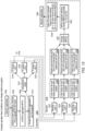
- Figure 11 may further correspond to the example of address set changes before encryption as shown in Figure 12 , according to some embodiments.
- Figure 12 illustrates different unicast link address sets such as Link 1 unicast address set (corresponding to Link 1, address set 1, Link 1, address set 2, Link 1, address set 3, and Link 1, Address set 4).
- Link 1 unicast address set corresponds to Link 1, address set 1, Link 1, address set 2, Link 1, address set 3, and Link 1, Address set 4
- Link 2 unicast address set corresponds to Link 2
- Address sets 1-4 corresponds to Link 3 Address sets 1-4 as shown in Figure 12 .
- the method of Figure 11 may further correspond to the example flow chart of an address change before encryption as shown in Figure 13 , according to some embodiments.
- a transmitter 1302 e.g., a STA or non-AP MI,D
- an application or internet browser 1304 which sets the current address, sequence number (SN) and packet number (PN) for a frame in 1306 as signaled by the application/internet 1304.
- the aggregated MAC-level Service Data Unit may aggregate the corresponding MAC-level Protocol Data Units (MPDUs) of the frame in 1308 and further encrypt the A-MSDU aggregation and the payload in 1310, according to some embodiments.
- MPDUs MAC-level Protocol Data Units
- the transmission buffer 1312 may then receive the encrypted frame and/or payload and A-MSDU and enter TX queue link 1 (e.g., 1314), TX queue link 2 (e.g., 1316), and TX queue link 3 (e.g., 1318) for transmission over the air to the receiver 1320.
- TX queue link 1 e.g., 1314
- TX queue link 2 e.g., 1316
- TX queue link 3 e.g., 1318
- the receiver 1320 may receive the transmissions of the TX links via receiver link 1 (e.g., 1322), receiver link 2 (e.g., 1324), and receiver link 3 (e.g., 1326).
- the receiver 1320 may then respectively verify in 1328, 1330, and 1332 (for the respective receiver links 1322, 1324, and 1326) that it has received appropriately addressed frames by verifying the received MAC headers of the frames.
- the receiver 1320 may then prepare and send respective block acknowledgements (ACKs) using the respective OTA received MAC addresses and SNs in 1334, 1336, and 1338 to indicate to the transmitter that it has performed successful reception.
- ACKs block acknowledgements
- the receiver 1320 may then decrypt the received MPDUs at 1340 as well as perform detection of duplicate MPDUs and reordering of said MPDUs according to the transaction identifiers (TIDs) and SNs in 1342, according to some embodiments.
- TIDs transaction identifiers
- SNs SNs
- the receiver 1320 may then check or verify the PN order of packets at 1344. For example, the receiver may verify for each packet that the sender address (SA) and destination address (DA) and has been received from a secure A-MSDU, according to some embodiments. Accordingly, once these have been verified, the packets may be delivered to the Internet / application 1346 from the receiver side.
- SA sender address
- DA destination address
- the method of Figure 11 may further involve an example of over-the-air (OTA) unicast address set randomization as described in Figure 14 , according to some embodiments.
- Figure 14 illustrates the number of randomized identifiers in individually addressed frames, according to some embodiments.
- a STA identifier type such as a STA link address unicast may correspond to one identifier per link as opposed to a STA association identifier (AID) of the same type which may correspond to just one identifier, according to some embodiments.
- a STA identifier type such as a STA link address unicast and a STA AID of the same type may correspond to one identifier per STA.
- identifier types such as encryption parameters
- UL or DL PN Offset unicast identifiers may correspond to one identifier per TID.
- identifier types such as reception parameters
- UL or DL SN Offset (TID) unicast as well as UL or DL TID offset identifiers may correspond to one identifier per TID.
- the physical (PHY) preamble identifiers UL and DL scrambler seeds may be associated with a number of identifiers which are reset on a per-STA basis.
- randomizing STA OTA MAC addresses may not be enough to deter or stop eavesdroppers since they may be able track the CPE STA from a scrambler seed, SN, and/or PN due to these values steadily increasing as a function of transmitted frames.
- each direction e.g., UL and DL
- Figure 15 illustrates how a STA may perform address set changes on all of its appropriate links at approximately the same time.
- a STA MLD may have two links STA_Link1 and STA_Link2 which are operating in an active mode corresponding to transmissions of frames to an AP MLD, according to some embodiments.
- the STA MLD may be configured to set all of its TX links to a power save or power conservation mode.
- a power management (PM) mode or parameter of the STA may correspond to certain values or bit values.
- the STA MLD and/or AP MLD may have previously determined or agreed upon a joint or concurrent address transition (e.g., an address change) time such that all the TX links corresponding address changes occur at a time during which the TX links (e.g., STA_Link1 and STA_Link2) are in power save mode.
- the STA may configure the TX links to resume transmitting (and using the new or updated addresses) in an active mode or state.
- a STA may be able to change or transition all its addresses at the same time by selecting a time when it does not have buffered UL frames with old addresses and setting all of its TX links to power save mode.
- the STA may buffer the frames and transmit the frames with new addresses after the address change.
- the newly received frames from the AP may include internet protocol (IP) addresses, user datagram / transmission control protocols (UDP/TCP) in addition to payloads.
- IP internet protocol
- UDP/TCP user datagram / transmission control protocols
- the STA may return to transmitting frames only with new addresses (as opposed to ones with the old addresses).
- the AP may only send frames with new addresses to the STA.
- Figure 16 illustrates an example of changing address sets on multiple links at different times. More specifically, Figure 16 illustrates how a STA may simplify the address change process by flexibly configuring different transmission links for power saving modes and active modes.
- the STA may keep certain link (e.g., STA_Link1) specific transmission UL buffers empty at or near a determined address change time (e.g., a Target OTA MAC Time (TOMAT) such as TOMAT_Link1) and further set the address changing link into power save mode.
- the STA may use other links (such as STA_Link2) to continue to facilitate the UL and DL frame transmissions.
- link e.g., STA_Link1
- TOMAT Target OTA MAC Time
- the STA may configure STA_Link1 with new addresses and to enter an active mode. Accordingly, STA_Link1 may be once again operating in the active mode and may be further allowed to immediately begin using the newly configured addresses for subsequent transmissions.
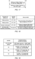
- Figures 17-19 illustrate example aspects and characteristics of signaling of new address set values, according to some embodiments.
- the signaling illustrated in Figures 17, 18 , and/or 19 may applicable to the method of Figure 11 (e.g., involving changing the address sets of all its links at the same time) and/or the technique illustrated in Figure 16 (e.g., involving changing address sets on multiple links at different times).
- Figure 17 illustrates an example communication flow diagram between an AP and a STA related to address configuration.
- the STA may transmit an Addresses Configure Request in 1702 to the AP corresponding to UL salt values, specified links, and specifying change times, according to some embodiments.
- the AP may transmit an Addresses Configure Response in 1704 including at least one of an indication of approval (e.g., "OK") or ACK as well as specifying links and providing DL salt value(s), according to some embodiments.
- the new parameter values for address changing may be calculated.
- a new salt value (e.g., in the Addresses Configure Request or Response) may allow the transmitter and receiver to calculate the new address, SN, PN and TID values.
- the UL and DL may have different link specific salt values since the STA defines UL values and the AP defines DL values.
- the AP and STA may setup individual address sets in association due to the new address sets being configured using the Addressed Configure Request and Addressed Configure Response and the new parameter values being calculated using them.
- Figure 18 illustrates various parameters that may be calculated based on information provided by the signaling devices.
- profiles start and end time parameters for the address set for the AP and STA may correspond to a value being calculated or provided (or be initiated by the STA or AP) that specifies start and end times of the address, according to some embodiments.
- the number of salt values may be used to determine a value or number of configured offset values or alternative addresses within the address set.
- a salt values table e.g., a lookup table corresponding to the number of salt values
- identifiers may be able to be calculated by the AP and STA using functions and received or previously calculated identifiers.
- the STA OTA MAC address identifier may use the function "F ( MAC Header random bits, Address Key, Salt) Mod (2 ⁇ 24 ) " to calculate the number of bits in the MAC header, according to some embodiments.
- the STA or AP may calculate the SN Offset using the SN and the function "F ( TA random bits, TID, Address key, Salt ) Mod(4096)".
- the PN and TID Offsets may be calculated using the functions F ( TA random bits, TID, Address key, Salt) Mod (2 ⁇ 46) or F ( TA random bits, Address key, Salt) Mod (2 ⁇ 46) respectively, according to some embodiments.
- an Address Change Request frame may include STA specific parameters such as OTA MAC Change interval, Max Random time and Max OTA MAC address change time (MOMAT) values. These values may be changed by re-associating or through a new protected management frameFor example, if an address change is performed through a re-association, the AP may need the STA to re-associate through a new management frame.
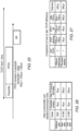
- the enhanced scheduling illustrated in Figure 20 may be used with the method of Figure 11 such that the address change before encryption changes addresses of all the TX links at the same time (e.g., the change time is the same for all links). Additionally or alternatively, the enhanced scheduling illustrated in Figure 20 may be used with the link offset mechanism such that the addresses for the links are separately updated for each link and at different times (e.g., as illustrated in Figure 16 ).
- randomization windows or random times for OTA address changes may be used with the TOMATs and MOMATs to further refine or define the OTA address changes.
- OTA MAC intervals such as X*, (X+1)*, (X+2)*, and (X+3)* ... (X+N)* may be used to define periods of time between a MOMAT and a subsequent TOMAT.
- the randomization window may be approximately two minutes while the OMA interval may be approximate ten minutes.
- TIDs and direction may be used to change the address sets in transmission at different times.
- the method of Figure 11 may utilize direction specific or TID specific transmissions to trigger an address change, according to some embodiments.
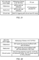
- Figure 21 illustrates an example scenario in which a STA or non-AP MLD may be transmitting old addresses and at some point the STA may receive a TOMAT. The STA may then receive a TID (e.g., TID 7) on a link (e.g., Link 1) corresponding to a new address set and subsequently configure the link for the new address set associated with TID 7.
- TID e.g., TID 7
- the STA may receive an additional TID (e.g., TID 3) after TID 7 and before a MOMAT and once again configure the link for the new address set associated with TID 3. Accordingly, and following the MOMAT, the STA (e.g., non-AP MLD) may then perform subsequent transmissions using the newly configured address set.
- the direction (UL or DL) of the TID may also be used for determining whether or not to perform an address change.
- the STA may be configured to perform an address change corresponding to received UL TIDs, according to some embodiments.
- the STA may be configured to perform an address change corresponding to received DL TIDs, according to some embodiments.
- an enhanced distributed channel access may be used to enable application client (AC) specific transmissions and quality of service (QoS) frameworks such that the direction specific or TID specific transmissions can be used to trigger an address change.
- each link may have link specific address change times. For example, with regard to Figure 11 involving address change before encryption, the old addresses may be buffered to link specific transmission buffers. This may cause each link to switch to new address at different times.
- each link when performing address changing after encryption, each link may have a different offset and therefore each link switches to new addresses at different times, according to some embodiments.
- Figure 22 is a communication flow diagram illustrating an example method of direction and TID specific OTA MAC address changing, according to some embodiments. More specifically, Figure 22 illustrates an embodiment directed toward systems, methods, and mechanisms for non-AP MLDs to perform address changing of one or more transmission (TX) links using received TIDs. Such techniques may aid in reduced latency, reduced power consumption, and/or improved security.
- TX transmission
- Non-AP MLD e.g., non-AP MLD 106
- AP MLD e.g., AP MLD 112
- the AP MLD and/or non-AP MLD may be as illustrated in and described with respect to various ones of the Figures herein, or more generally in conjunction with any of the computer circuitry, systems, devices, elements, or components shown in the above Figures, among others, as desired.
- a processor (and/or other hardware) of such a device may be configured to cause the device to perform any combination of the illustrated method elements and/or other method elements.
- processors may cause a wireless device, STA, UE, non-AP MLD, and/or AP MLD, or other device to perform such method elements.
- the methods shown may be used in conjunction with any of the systems, methods, or devices shown in the Figures, among other devices. In various embodiments, some of the method elements shown may be performed concurrently, in a different order than shown, or may be omitted. Additional method elements may also be performed as desired. As shown, this method may operate as follows.
- a non-AP MLD may transmit, using one or more respective transmission (TX) links, one or more uplink frames to an AP MLD using one or more respective addresses corresponding to one or more respective reception (RX) links of the AP MLD.
- TX transmission
- RX reception
- a STA may be in communication with an AP and be transmitting frames using currently configured addresses, according to some embodiments.
- the non-AP MLD may receive, one or more downlink frames including one or more transaction identifiers (TIDs) and an Address Change Request frame, according to some embodiments.
- the Address Change Request frame may include information corresponding to one or more target over-the-air media access control address change times (TOMATs) and one or more maximum over-the-air media access control address change times (MOMATs), according to some embodiments.
- the one or more TIDs may be associated with one or more new addresses corresponding to the one or more respective RX links of the AP-MLD.
- a STA may receive information from the AP related to the timing or scheduling of performing an address change. Additionally or alternatively, the information may include new addresses to be used by the STA for subsequent transmissions, according to some embodiments.
- the non-AP MLD may configure, based on the one or more TIDs and during a time interval defined by the one or more TOMATs and the one or more MOMATs, the one or more respective TX links with the one or more new addresses, according to some embodiments.
- the TOMAT may correspond to a target time for the STA to initiate or perform an address change for one or more TX links.
- the MOMAT may correspond to a maximum time at which the STA should have already performed an address change, according to some embodiments.
- the non-AP MLD may transmit, to the AP MLD, one or more additional frames using the one or more respective new addresses, according to some embodiments. For example, having configured the appropriate TX links during the specified time window and using the new addresses indicated in the TIDs, the STA may continue or resume transmissions to the AP using the newly configured addresses.
- MOMATs or TOMATs may be altered or changed by re-associating or via a protected management frame.
- various parameters of the MOMATs or TOMATs may be configured to such that the scheduling of the address change can be flexibly change.
- the target time e.g., TOMAT
- the TOMAT may be decreased such that the address change is performed quickly after entering the power save mode.
- the MOMAT may be decreased such that the address change is performed before a maximum allowed time has elapsed.
- the MOMAT may be increased so as to allow the non-AP MLD additional time to perform the address change or other procedures under various scenarios. For example, large amounts of data traffic may correspond to longer address change times, according to some embodiments.
- new addresses may be calculated by the AP MLD or the non-AP MLD using one or more salt values.
- the AP MLD or non-AP MLD may generate salt values corresponding to a various randomly generated values and lengths.
- the salt value may be used as an input in a function for hashing data. Accordingly, utilizing the hashed values and salt values may provide a way to generate more secure and/or random addresses to be used for address changes.
- the salt values may be usable by the AP MLD or non-AP MLD to calculate one or more sequence numbers (SNs), one or more packet numbers (PNs), or one or more transaction identifiers (TIDs) of various frames.
- SNs sequence numbers
- PNs packet numbers
- TIDs transaction identifiers
- uplink salt values may correspond to the respective TX links of the non-AP MLD and downlink salt values may correspond to the one or more respective RX links of the AP MLD.
- an address change time e.g., TOMAT
- TOMAT address change time
- the AP and STA may not have exchanged any frames related to the address change, according to some embodiments.
- FIGS 23-24 illustrate example aspects of address changing by controlling the old and new address assignments for the packet, according to some embodiments.
- transmitters may have a large quantity of low priority traffic to buffer.
- the transmitter starts to use the new addresses for all TIDs at the same time, it could result in lower priority TIDs (e.g., corresponding to a low priority AC) frames with old addresses taking a longer time to transmit than higher priority TIDs.
- this scenario may occur more frequently when there are large amounts of data traffic being transmitted in bursts with ACs of differing priorities. Accordingly, it may be beneficial for the transmitter to minimize address handling complexity as well as reducing the chance of eavesdroppers detecting the address change by shortening the time when some TIDs use old addresses and other TIDs use new addresses.
- a STA may be transmitting frames using old address and receive multiple TIDs (e.g., TID 0 and TID 7) before a TOMAT. These multiple TIDs may be received at different times and be further associated with new addresses. Accordingly, after the TOMAT, the STA may configure one or more of its TX links with the new addresses associated with the TIDs at a specific transition time. For example, the transition time may be specified such the address change occurs before the MOMAT. Furthermore, the STA may be configured to transmit all of the OTA frames with the new addresses of the TIDs during a specific target time. For example, the transmitter may seek to perform the transmission of the OTA frames just after the TOMAT. Accordingly, after these transmissions and the MOMAT, the STA may subsequently use the new addresses for future transmissions.
- TID 0 and TID 7 may be transmitted at different times and be further associated with new addresses.
- the STA may configure one or more of its TX links with the new addresses associated with the TIDs at a specific transition time. For example
- Figure 24 more specifically illustrates how a transmitter may use new addresses for each TID at different times.
- a new frame to be transmitted at 2402 it may be associated with TIDs of varying priorities.
- TID 0 may correspond to a lower priority AC which had changed to a new address set before TID 7 (corresponding to a higher priority AC).
- the STA may use the new addresses 2404 in TID specific transmission buffers.
- the STA may use a buffered frame with the new address set for TID 0 followed by buffered frames with the old address set for TID 0, according to some embodiments.
- Figures 25-27 illustrate example aspects optimizing transmission efficiency during address changes, according to some embodiments.
- the total time for the TXOP would be 390 ⁇ s as compared to the 540 ⁇ s for two TXOPs corresponding to different addresses.
- Figure 30 illustrates example aspects of frame transmission techniques that can be applied at the resource unit (RU) level.
- RU resource unit
- a new AID in a trigger frame it may be used to trigger the STA such that the STA may be able to transmit frames with new addresses quickly, according to some embodiments. Accordingly, this quick transition may make it difficult for eavesdroppers to intercept communications or determine that an address change has occurred.
- the AP may be capable of receiving old or new addressed frames in a high efficiency trigger based physical protocol data unit (HE TB PPDU). Accordingly, the STA may allocate frames from old or new addresses and further transmit the old addresses first. However, an old address transmitted with a new AID may alert or inform eavesdroppers of a potential address change.
- HE TB PPDU high efficiency trigger based physical protocol data unit
- the MPDUs of the frames in the HE TB PDDUs may be addressed using the new current addresses and the STA may transmit on the corresponding allocated RU.
- the AP may separately trigger old frames and new frames by using the respective AID such that the AID Old triggers frames with old/previous addresses and the AID new triggers frames with new or current addresses.
- the trigger frame includes old and new AIDs, a technique using multi-RU triggering with the old and new AID values may be utilized, as further discussed below with regard to Figures 33-34 .
- Figure 33 illustrates example aspects and information bits of a buffer status report and the content or information that may be used for address changing operations, according to some embodiments.
- the BSR may include an ACI Bitmap which may be used to signal or indicate the ACs to which the report is provided.
- the BSR may include a Delta TID and a ACI Bitmap used for signaling or indicating the TIDs in which the STA has buffered traffic.
- the BSR may include information bits corresponding to an ACI High parameter which can be used to signal or indicate the highest AC in which the STA has buffered traffic.
- the BSR may include information bits corresponding to a Scaling Factor which can be used to signal or indicate a scaling factor for queue size counters.
- Wi-Fi 7 may support multi-RU DL MU PPDU such that the AP may allocate two RUs in DL MU PPDU for the same STA, according to some embodiments.
- Wi-Fi 8 may support Multiple-RU triggering such that the AP may allocate two separate RUs in trigger frame transmissions by using the AID of the STA.
- the AP may allocate RUs with old and the new AID. Additionally, this may provide some security benefits or protection regarding the transmitted payload since, for an eavesdropper to receive the payload, they would combine both received RUs.
- the STA may use either new or old addresses if the AP allocates RUs with old and new AIDs to the STA, according to some embodiments.
- triggered HE TB PPDU or MU PPDU may only have a few combinations for two RU allocations, so the protection of the transmission may be lessened in this scenario.
- processors may cause a wireless device, STA, UE, non-AP MLD, and/or AP MLD, or other device to perform such method elements.
- the methods shown may be used in conjunction with any of the systems, methods, or devices shown in the Figures, among other devices. In various embodiments, some of the method elements shown may be performed concurrently, in a different order than shown, or may be omitted. Additional method elements may also be performed as desired. As shown, this method may operate as follows.
- the non-AP MLD may configure, based on the reception of the trigger frame including the one or more new AIDs, the one or more respective TX links with the one or more respective new addresses and the one or more new AIDs, according to some embodiments.
- the STA may configure the TX links to utilize the new AIDs and addresses for subsequent communications or transmissions to the AP, according to some embodiments.
- the non-AP MLD may transmit, to the AP MLD, one or more additional frames using the one or more respective new addresses and the one or more new AIDs.
- the STA may continue or resume transmissions to the AP using the newly configured addresses and AIDs, according to some embodiments.
- the trigger frame may include a buffer status report poll (BSRP). Additionally or alternatively, the non-AP MLD may transmit, in response to receiving the trigger frame including the BSRP, a buffer status report (BSR) to the AP MLD.
- BSR buffer status report
- the BSR may indicate the amount of buffered traffic for at least one of the one or more respective addresses or one or more respective new addresses.
- the address configuration may need to be performed quickly in response to a trigger frame.
- the trigger frame may solicit frames with new addresses and it may be beneficial for these frames to be transmitted quickly (e.g., on the order of or approximately 16 ⁇ s) after the trigger frame. This fast address change and resumption of transmissions may allow for more seamless communication and efficient data transfers between the STA and AP.
- the DL frames transmitter, receiver, and/or base service set identifier (BSSID) addresses may be used to indicate whether the new addresses or old addresses are in use.
- the receiver STA may not be able to detect or determine from a recommended or received AID field value in a trigger frame whether or not the AP request frames being transmitted are using old or new addresses, according to some embodiments. This may be at least partly based on the AID values having offset (e.g., overlapping) values, according to some embodiments. Accordingly, regardless of the recommended or received AID value in the trigger frame, the STA may select the TID that it transmits to the AP, according to some embodiments.
- the address in a trigger frame and/or the AID values may be used to identify the triggered devices, according to some embodiments.
- the BSSID and MAC addresses may be used to identify the triggered devices, according to some embodiments.
- personally identifiable information should follow privacy policies and practices that are generally recognized as meeting or exceeding industry or governmental requirements for maintaining the privacy of users.
- personally identifiable information data should be managed and handled so as to minimize risks of unintentional or unauthorized access or use, and the nature of authorized use should be clearly indicated to users.
- Embodiments of the present disclosure may be realized in any of various forms. For example, some embodiments may be realized as a computer-implemented method, a computer-readable memory medium, or a computer system. Other embodiments may be realized using one or more custom-designed hardware devices such as ASICs. Other embodiments may be realized using one or more programmable hardware elements such as FPGAs.
- a non-transitory computer-readable memory medium may be configured so that it stores program instructions and/or data, where the program instructions, if executed by a computer system, cause the computer system to perform a method, e.g., any of the method embodiments described herein, or, any combination of the method embodiments described herein, or, any subset of any of the method embodiments described herein, or, any combination of such subsets.
- a wireless device may be configured to include a processor (and/or a set of processors) and a memory medium, where the memory medium stores program instructions, where the processor is configured to read and execute the program instructions from the memory medium, where the program instructions are executable to cause the wireless device to implement any of the various method embodiments described herein (or, any combination of the method embodiments described herein, or, any subset of any of the method embodiments described herein, or, any combination of such subsets).
- the device may be realized in any of various forms.
Landscapes
- Engineering & Computer Science (AREA)
- Computer Networks & Wireless Communication (AREA)
- Signal Processing (AREA)
- Databases & Information Systems (AREA)
- Mobile Radio Communication Systems (AREA)
Applications Claiming Priority (3)
| Application Number | Priority Date | Filing Date | Title |
|---|---|---|---|
| US202263357949P | 2022-07-01 | 2022-07-01 | |
| US18/324,089 US20240007846A1 (en) | 2022-07-01 | 2023-05-25 | Enhanced Address Changing for Wireless Networking Systems |
| EP23182089.5A EP4307825B1 (de) | 2022-07-01 | 2023-06-28 | Verbesserter adressenwechsel für drahtlose netzwerksysteme |
Related Parent Applications (2)
| Application Number | Title | Priority Date | Filing Date |
|---|---|---|---|
| EP23182089.5A Division EP4307825B1 (de) | 2022-07-01 | 2023-06-28 | Verbesserter adressenwechsel für drahtlose netzwerksysteme |
| EP23182089.5A Division-Into EP4307825B1 (de) | 2022-07-01 | 2023-06-28 | Verbesserter adressenwechsel für drahtlose netzwerksysteme |
Publications (2)
| Publication Number | Publication Date |
|---|---|
| EP4529247A2 true EP4529247A2 (de) | 2025-03-26 |
| EP4529247A3 EP4529247A3 (de) | 2025-06-18 |
Family
ID=87036792
Family Applications (2)
| Application Number | Title | Priority Date | Filing Date |
|---|---|---|---|
| EP25156875.4A Pending EP4529247A3 (de) | 2022-07-01 | 2023-06-28 | Verbesserter adressenwechsel für drahtlose netzwerksysteme |
| EP23182089.5A Active EP4307825B1 (de) | 2022-07-01 | 2023-06-28 | Verbesserter adressenwechsel für drahtlose netzwerksysteme |
Family Applications After (1)
| Application Number | Title | Priority Date | Filing Date |
|---|---|---|---|
| EP23182089.5A Active EP4307825B1 (de) | 2022-07-01 | 2023-06-28 | Verbesserter adressenwechsel für drahtlose netzwerksysteme |
Country Status (3)
| Country | Link |
|---|---|
| US (1) | US20240007846A1 (de) |
| EP (2) | EP4529247A3 (de) |
| KR (1) | KR20240003733A (de) |
Families Citing this family (6)
| Publication number | Priority date | Publication date | Assignee | Title |
|---|---|---|---|---|
| CN110536386B (zh) * | 2019-08-09 | 2023-04-25 | 中兴通讯股份有限公司 | 唤醒信号的传输方法、装置和存储介质 |
| US20230345299A1 (en) * | 2022-04-22 | 2023-10-26 | Meta Platforms Technologies, Llc | Systems and methods of requesting buffer status for wireless p2p traffic |
| US12563547B2 (en) * | 2022-11-11 | 2026-02-24 | Cisco Technology, Inc. | AP controlled peer-to-peer multi-link operations signaling |
| EP4676125A1 (de) * | 2023-02-27 | 2026-01-07 | LG Electronics Inc. | Verfahren und vorrichtung für gerätebasiertes roaming mit mehreren verbindungen in einem wlan-system |
| US20250106182A1 (en) * | 2023-09-23 | 2025-03-27 | Cisco Technology, Inc. | Epoch scheme for station privacy |
| USD1116895S1 (en) * | 2024-01-26 | 2026-03-10 | Samsung Electronics Co., Ltd. | Smart watch band |
Family Cites Families (7)
| Publication number | Priority date | Publication date | Assignee | Title |
|---|---|---|---|---|
| CN104955038B (zh) * | 2014-03-25 | 2019-06-11 | 华为终端有限公司 | 分配寻址标识的方法及接入点、站点和通信系统 |
| SG10202000280YA (en) * | 2020-01-10 | 2021-08-30 | Panasonic Ip Corp America | Communication apparatus and communication method for multi-link secured retransmissions |
| US11924823B2 (en) * | 2020-02-22 | 2024-03-05 | Nxp Usa, Inc. | Multi-link device association and reassociation |
| US11973679B2 (en) * | 2020-08-03 | 2024-04-30 | Intel Corporation | Enhanced frame exchange and multi-link device messaging for secure communications |
| US20220124856A1 (en) * | 2020-10-21 | 2022-04-21 | Qualcomm Incorporated | Direct link communications in multi-link operations |
| US11832325B2 (en) * | 2020-10-29 | 2023-11-28 | Lg Electronics Inc. | Allocation of link ID for transmitting multi-link information |
| US12016067B2 (en) * | 2020-12-24 | 2024-06-18 | Intel Corporation | Association identification re-assignment |
-
2023
- 2023-05-25 US US18/324,089 patent/US20240007846A1/en active Pending
- 2023-06-28 EP EP25156875.4A patent/EP4529247A3/de active Pending
- 2023-06-28 EP EP23182089.5A patent/EP4307825B1/de active Active
- 2023-06-29 KR KR1020230084186A patent/KR20240003733A/ko active Pending
Also Published As
| Publication number | Publication date |
|---|---|
| US20240007846A1 (en) | 2024-01-04 |
| EP4307825A1 (de) | 2024-01-17 |
| EP4529247A3 (de) | 2025-06-18 |
| KR20240003733A (ko) | 2024-01-09 |
| EP4307825B1 (de) | 2025-03-26 |
Similar Documents
| Publication | Publication Date | Title |
|---|---|---|
| EP4002899B1 (de) | Multilink-vorrichtung-datenschutz und -funktionsverbesserungen | |
| EP4307825B1 (de) | Verbesserter adressenwechsel für drahtlose netzwerksysteme | |
| US12284560B2 (en) | Channel switching | |
| US20250240685A1 (en) | Channel Switching | |
| EP4554148B1 (de) | Verschlüsselung und schutz von mac kopfteilen und steuerrahmen | |
| CN117336901A (zh) | 用于无线联网系统的增强地址改变 | |
| WO2022272003A1 (en) | Channel switching and operating channel validation | |
| US20240155605A1 (en) | Frequency Domain Partial Transmission | |
| US20230319722A1 (en) | Multi-link single radio suspension and operating parameters | |
| US12507229B2 (en) | WLAN enhancements for co-existence | |
| EP4531466A2 (de) | Verbesserungen an abtastungs- und zugangspunktauswahl für drahtlose netzwerksysteme | |
| US11997673B2 (en) | Negative-block ACK based Wi-Fi MAC protocol | |
| US20250150904A1 (en) | Data path control in seamless roaming | |
| US20240306062A1 (en) | Enhanced Roaming | |
| EP4354961A1 (de) | Unterstütztes roaming | |
| EP4329421A1 (de) | Rekonfigurierte triggerrahmenantwort | |
| US20240107504A1 (en) | Transmission Methods for Low Latency IEEE 802.11bx Communications | |
| CN116896790A (zh) | 针对共存的wlan增强 | |
| EP4489460B1 (de) | Verbesserter integritätsschutz für drahtlose netzwerksysteme | |
| CN117896795A (zh) | 辅助漫游 | |
| US20260129638A1 (en) | Methods for Enhanced Low Latency Transmissions in 802.11 | |
| EP4608056A1 (de) | Verbesserte leistungsverwaltungstechniken für mehrverbindungsbetrieb | |
| EP4738984A1 (de) | Verfahren für erweiterte übertragungen mit niedriger latenz in 802.11 | |
| EP4531487A1 (de) | Koordinierter kanalzugriff in drahtlosen kommunikationssystemen | |
| CN122002258A (zh) | 用于802.11中的增强型低时延发送的方法 |
Legal Events
| Date | Code | Title | Description |
|---|---|---|---|
| PUAI | Public reference made under article 153(3) epc to a published international application that has entered the european phase |
Free format text: ORIGINAL CODE: 0009012 |
|
| STAA | Information on the status of an ep patent application or granted ep patent |
Free format text: STATUS: REQUEST FOR EXAMINATION WAS MADE |
|
| 17P | Request for examination filed |
Effective date: 20250210 |
|
| AC | Divisional application: reference to earlier application |
Ref document number: 4307825 Country of ref document: EP Kind code of ref document: P |
|
| AK | Designated contracting states |
Kind code of ref document: A2 Designated state(s): AL AT BE BG CH CY CZ DE DK EE ES FI FR GB GR HR HU IE IS IT LI LT LU LV MC ME MK MT NL NO PL PT RO RS SE SI SK SM TR |
|
| REG | Reference to a national code |
Ref country code: DE Ref legal event code: R079 Free format text: PREVIOUS MAIN CLASS: H04W0012000000 Ipc: H04W0076110000 |
|
| PUAL | Search report despatched |
Free format text: ORIGINAL CODE: 0009013 |
|
| AK | Designated contracting states |
Kind code of ref document: A3 Designated state(s): AL AT BE BG CH CY CZ DE DK EE ES FI FR GB GR HR HU IE IS IT LI LT LU LV MC ME MK MT NL NO PL PT RO RS SE SI SK SM TR |
|
| RIC1 | Information provided on ipc code assigned before grant |
Ipc: H04L 101/622 20220101ALN20250514BHEP Ipc: H04W 12/06 20210101ALN20250514BHEP Ipc: H04W 84/12 20090101ALN20250514BHEP Ipc: H04W 76/15 20180101ALN20250514BHEP Ipc: H04L 61/5038 20220101ALI20250514BHEP Ipc: H04W 76/11 20180101AFI20250514BHEP |