EP4529152A1 - Schaltervorrichtung, steuerungsverfahren und bildgebungssystem - Google Patents
Schaltervorrichtung, steuerungsverfahren und bildgebungssystem Download PDFInfo
- Publication number
- EP4529152A1 EP4529152A1 EP23807370.4A EP23807370A EP4529152A1 EP 4529152 A1 EP4529152 A1 EP 4529152A1 EP 23807370 A EP23807370 A EP 23807370A EP 4529152 A1 EP4529152 A1 EP 4529152A1
- Authority
- EP
- European Patent Office
- Prior art keywords
- video
- video data
- camera
- switching
- switch unit
- Prior art date
- Legal status (The legal status is an assumption and is not a legal conclusion. Google has not performed a legal analysis and makes no representation as to the accuracy of the status listed.)
- Pending
Links
Images


Classifications
-
- H—ELECTRICITY
- H04—ELECTRIC COMMUNICATION TECHNIQUE
- H04N—PICTORIAL COMMUNICATION, e.g. TELEVISION
- H04N5/00—Details of television systems
- H04N5/222—Studio circuitry; Studio devices; Studio equipment
- H04N5/262—Studio circuits, e.g. for mixing, switching-over, change of character of image, other special effects ; Cameras specially adapted for the electronic generation of special effects
- H04N5/268—Signal distribution or switching
-
- G—PHYSICS
- G06—COMPUTING OR CALCULATING; COUNTING
- G06F—ELECTRIC DIGITAL DATA PROCESSING
- G06F3/00—Input arrangements for transferring data to be processed into a form capable of being handled by the computer; Output arrangements for transferring data from processing unit to output unit, e.g. interface arrangements
- G06F3/14—Digital output to display device ; Cooperation and interconnection of the display device with other functional units
- G06F3/1423—Digital output to display device ; Cooperation and interconnection of the display device with other functional units controlling a plurality of local displays, e.g. CRT and flat panel display
- G06F3/1446—Digital output to display device ; Cooperation and interconnection of the display device with other functional units controlling a plurality of local displays, e.g. CRT and flat panel display display composed of modules, e.g. video walls
-
- H—ELECTRICITY
- H04—ELECTRIC COMMUNICATION TECHNIQUE
- H04N—PICTORIAL COMMUNICATION, e.g. TELEVISION
- H04N23/00—Cameras or camera modules comprising electronic image sensors; Control thereof
- H04N23/60—Control of cameras or camera modules
-
- H—ELECTRICITY
- H04—ELECTRIC COMMUNICATION TECHNIQUE
- H04N—PICTORIAL COMMUNICATION, e.g. TELEVISION
- H04N23/00—Cameras or camera modules comprising electronic image sensors; Control thereof
- H04N23/60—Control of cameras or camera modules
- H04N23/667—Camera operation mode switching, e.g. between still and video, sport and normal or high- and low-resolution modes
-
- H—ELECTRICITY
- H04—ELECTRIC COMMUNICATION TECHNIQUE
- H04N—PICTORIAL COMMUNICATION, e.g. TELEVISION
- H04N23/00—Cameras or camera modules comprising electronic image sensors; Control thereof
- H04N23/90—Arrangement of cameras or camera modules, e.g. multiple cameras in TV studios or sports stadiums
-
- H—ELECTRICITY
- H04—ELECTRIC COMMUNICATION TECHNIQUE
- H04N—PICTORIAL COMMUNICATION, e.g. TELEVISION
- H04N5/00—Details of television systems
- H04N5/222—Studio circuitry; Studio devices; Studio equipment
- H04N5/2224—Studio circuitry; Studio devices; Studio equipment related to virtual studio applications
-
- H—ELECTRICITY
- H04—ELECTRIC COMMUNICATION TECHNIQUE
- H04N—PICTORIAL COMMUNICATION, e.g. TELEVISION
- H04N5/00—Details of television systems
- H04N5/222—Studio circuitry; Studio devices; Studio equipment
- H04N5/262—Studio circuits, e.g. for mixing, switching-over, change of character of image, other special effects ; Cameras specially adapted for the electronic generation of special effects
- H04N5/265—Mixing
Definitions
- the present technology relates to a switcher device for video data, a method for controlling a switcher device, and an imaging system including a switcher device.
- a technology is known in which a performer performs acting with what is called a green back and then a background video is synthesized.
- an imaging system in which, in a studio provided with a large display, a background video is displayed on the display, and a performer performs acting in front thereof, whereby the performer and the background can be imaged, and the imaging system is known as what is called virtual production, in-camera VFX, or light emitting diode (LED) wall virtual production.
- virtual production in-camera VFX, or light emitting diode (LED) wall virtual production.
- Patent Document 1 discloses a technology of a system that images a performer acting in front of a background video.
- Patent Document 1 US Patent Application Publication No. 2020/0145644 A
- the appearance of the background should be different according to the position of the camera with respect to the display and the imaging direction.
- the background video at least the video in the range within the angle of view of the camera in the display
- the present disclosure proposes a technique for obtaining an appropriate video in a system in which a video displayed on a display is captured by a plurality of cameras and a main line video is switched by a switcher.
- a switcher device includes: a first switch unit that receives, as video data to be displayed on a display, a plurality of pieces of video data including video content corresponding to each of a plurality of cameras as input, selects one of the plurality of pieces of video data, and outputs the selected video data; a second switch unit that receives a plurality of pieces of video data obtained by capturing a video displayed on the display by the plurality of cameras as input, selects one of the plurality of pieces of video data, and outputs the selected video data; and a control unit that performs control to cause the first switch unit to execute switching of video data in response to a trigger of video switching, and, after a predetermined switching delay time elapses, to cause the second switch unit to execute switching to video data by a camera corresponding to the video data after the switching in the first switch unit.
- a background video or the like with video content corresponding to the position and viewing direction of each camera is prepared, and selectively supplied to the display via the switcher device to be displayed.
- Each camera captures a video of the display, and the second switch unit selects and outputs the video.
- the second switch unit is switched after a predetermined switching delay time.
- video or “image” includes both a still image and a moving image.
- video refers not only to a state in which the video is displayed on a display, but also video data in a state in which the video data is not displayed on a display may be comprehensively referred to as "video”.
- a background video before being displayed on a display, a video captured by a camera, and a background video or a captured video switched by a switcher are not a video actually being displayed but video data.
- video data is referred to as "background video”, “captured video”, or the like for convenience.
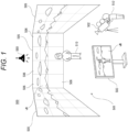
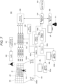
- Fig. 1 schematically illustrates an imaging system 500.
- the imaging system 500 is a system that performs imaging as virtual production, and a part of equipment arranged in an imaging studio is illustrated in the drawing.
- a performance area 501 in which a performer 510 performs performance such as acting is provided.
- a large display device is arranged on at least the back surface, the left and right side surfaces, and the upper surface of the performance area 501.
- the device type of the display device is not limited, the drawing illustrates an example in which an LED wall 505 is used as an example of the large display device.
- One LED wall 505 forms a large panel by vertically and horizontally connecting and arranging a plurality of LED panels 506.
- the size of the LED wall 505 is not particularly limited, but only needs to be a size that is necessary or sufficient as a size for displaying a background when the performer 510 is imaged.
- a necessary number of lights 580 are arranged at necessary positions such as above or on the side of the performance area 501 to illuminate the performance area 501.
- a camera 502 for imaging a movie or other video content is arranged.
- a camera operator 512 can move the position of the camera 502, and can perform an operation of an imaging direction, an angle of view, or the like.
- movement, angle of view operation, or the like of the camera 502 is performed by remote control.
- the camera 502 may automatically or autonomously move or change the angle of view. For this reason, the camera 502 may be mounted on a camera platform or a mobile body.
- the camera 502 collectively captures the performer 510 in the performance area 501 and the video displayed on the LED wall 505. For example, by displaying a scene as a background video vB on the LED wall 505, it is possible to capture a video similar to that in a case where the performer 510 actually exists and performs acting at the place of the scene.
- An output monitor 503 is arranged near the performance area 501.
- the video being captured by the camera 502 is displayed on the output monitor 503 in real time as a monitor video vM.
- a director and staff who produce a video content can check the captured video.
- the imaging system 500 that images performance of the performer 510 in the background of the LED wall 505 in the imaging studio has various advantages as compared with the green back shooting.
- the performer 510 can easily perform acting, and the quality of acting is improved. Furthermore, it is easy for the director and other staff members to determine whether or not the acting of the performer 510 matches the background or the situation of the scene.
- a chroma key composition may be unnecessary or color correction or reflection composition may be unnecessary.
- the background screen does not need to be added, which is also helpful to improve efficiency.
- the hue of the green increases on the performer's body, dress, and objects, and thus correction thereof is necessary. Furthermore, in the case of the green back shooting, in a case where there is an object in which a surrounding scene is reflected, such as glass, a mirror, or a snowdome, it is necessary to generate and synthesize an image of the reflection, but this is troublesome work.
- the hue of the green does not increase, and thus the correction is unnecessary. Furthermore, by displaying the background video vB, the reflection on the actual article such as glass is naturally obtained and captured, and thus, it is also unnecessary to synthesize the reflection video.
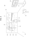
- the background video vB will be described with reference to Figs. 2 and 3 . Even if the background video vB is displayed on the LED wall 505 and captured together with the performer 510, the background of the captured video becomes unnatural only by simply displaying the background video vB. This is because a background that is three-dimensional and has depth is actually used as the background video vB in a planar manner.
- the camera 502 can image the performer 510 in the performance area 501 from various directions, and can also perform a zoom operation.
- the performer 510 also does not stop at one place. Then, the actual appearance of the background of the performer 510 should change according to the position, the imaging direction, the angle of view, and the like of the camera 502, but such a change cannot be obtained in the background video vB as the planar video. Accordingly, the background video vB is changed so that the background is similar to the actual appearance including a parallax.
- Fig. 2 illustrates a state in which the camera 502 is imaging the performer 510 from a position on the left side of the drawing
- Fig. 3 illustrates a state in which the camera 502 is imaging the performer 510 from a position on the right side of the drawing.
- a capturing region video vBC is illustrated in the background video vB.
- the background video vB described here indicates the entire video displayed as the background including the capturing region video vBC (inner frustum).
- the range of the capturing region video vBC corresponds to a range actually imaged by the camera 502 in the display surface of the LED wall 505.
- the capturing region video vBC is a video that is transformed so as to express a scene that is actually viewed when the position of the camera 502 is set as a viewpoint according to the position, the imaging direction, the angle of view, and the like of the camera 502.
- 3D background data that is a 3D model as a background is prepared, and the capturing region video vBC is sequentially rendered on the basis of the viewpoint position of the camera 502 with respect to the 3D background data in real time.
- the range of the capturing region video vBC is actually a range slightly wider than the range imaged by the camera 502 at the time point. This is to prevent the video of the outer frustum from being reflected due to a drawing delay and to avoid the influence of the diffracted light from the video of the outer frustum when the range of imaging is slightly changed by panning, tilting, zooming, or the like of the camera 502.
- the video of the capturing region video vBC rendered in real time in this manner is synthesized with the video of the outer frustum.
- the video of the outer frustum used in the background video vB is rendered in advance on the basis of the 3D background data, and the video is incorporated as the capturing region video vBC rendered in real time into a part of the video of the outer frustum to generate the entire background video vB.
- the background of the range imaged together with the performer 510 is captured as a video corresponding to the viewpoint position change accompanying the actual movement of the camera 502.
- the monitor video vM including the performer 510 and the background is displayed on the output monitor 503, and this is the captured video.
- the background of the monitor video vM is the capturing region video vBC. That is, the background included in the captured video is a real-time rendered video.
- the background video vB including the capturing region video vBC is changed in real time so that not only the background video vB is simply displayed in a planar manner but also a video similar to that in a case of actually imaging on location can be captured.
- a processing load of the system is also reduced by rendering only the capturing region video vBC as a range reflected by the camera 502 in real time instead of the entire background video vB displayed on the LED wall 505.
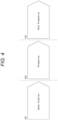
- the video content producing step is roughly divided into three stages.
- the stages are asset creation ST1, production ST2, and post-production ST3.
- the asset creation ST1 is a step of producing 3D background data for displaying the background video vB.
- the background video vB is generated by performing rendering in real time using the 3D background data at the time of imaging.
- 3D background data as a 3D model is produced in advance.
- Examples of a method of producing the 3D background data include full computer graphics (CG), point cloud data (Point Cloud) scan, and photogrammetry.
- the full CG is a method of producing a 3D model with computer graphics.
- the full CG requires the most man-hours and time, but is preferably used in a case where an unrealistic video, a video that is difficult to capture in practice, or the like is desired to be the background video vB.
- the point cloud data scanning is a method of generating a 3D model based on the point cloud data by performing distance measurement from a certain position using, for example, LiDAR, capturing an image of 360 degrees by a camera from the same position, and placing color data captured by the camera on a point measured by the LiDAR.
- a 3D model can be produced in a short time. Furthermore, it is easy to produce a 3D model with higher definition than that of the photogrammetry.
- the photogrammetry is a photogrammetry technology for analyzing parallax information from two-dimensional images obtained by capturing an object from a plurality of viewpoints to obtain the dimensions and the shape.
- 3D model production can be performed in a short time.
- the point cloud information acquired by the LiDAR may be used in the 3D data generation by the photogrammetry.
- a 3D model to be 3D background data is produced using these methods.
- the above methods may be used in combination.
- a part of a 3D model produced by the point cloud data scanning or the photogrammetry is produced by CG and synthesized or the like.
- the production ST2 is a step of performing imaging in the imaging studio as illustrated in Fig. 1 .
- Element technologies in this case include real-time rendering, background display, camera tracking, illumination control, and the like.
- the real-time rendering is rendering processing for obtaining the capturing region video vBC at each time point (each frame of the background video vB) as described with reference to Figs. 2 and 3 . This is to render the 3D background data produced in the asset creation ST1 from a viewpoint corresponding to the position of the camera 502 or the like at each time point.
- the real-time rendering is performed to generate the background video vB of each frame including the capturing region video vBC, and the background video vB is displayed on the LED wall 505.
- the camera tracking is performed to obtain imaging information by the camera 502, and tracks position information, the imaging direction, the angle of view, and the like at each time point of the camera 502.
- the imaging information is information linked with or associated with a video as metadata.
- the imaging information includes position information of the camera 502 at each frame timing, a direction of the camera, an angle of view, a focal length, an F value (aperture value), a shutter speed, lens information, and the like.
- the illumination control is to control the state of illumination in the imaging system 500, and specifically, to control the light amount, emission color, illumination direction, and the like of the light 580.
- the illumination control is performed according to time setting, place setting, and the like of a scene to be imaged.
- the post-production ST3 indicates various processing performed after imaging. For example, video correction, video adjustment, clip editing, video effect, and the like are performed.
- a synthesis of a CG video or a special effect video or the like may be performed.
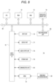
- the sync generator 540 generates a synchronization signal for synchronizing frame timings of display videos by the LED panels 506 and a frame timing of imaging by the camera 502, and supplies the synchronization signal to the respective LED processors 570 and the camera 502. However, this does not prevent output from the sync generator 540 from being supplied to the rendering engine 520.
- the camera tracker 560 generates imaging information by the camera 502 at each frame timing and supplies the imaging information to the rendering engine 520. For example, the camera tracker 560 detects the position information of the camera 502 relative to the position of the LED wall 505 or a predetermined reference position and the imaging direction of the camera 502 as one piece of the imaging information, and supplies them to the rendering engine 520.
- the camera tracker 560 As a specific detection method by the camera tracker 560, there is a method of randomly arranging reflectors on the ceiling and detecting a position from reflected light of infrared light emitted from the camera tracker 560 to the reflectors, the camera tracker 560 being assembled to the camera 502. Furthermore, as a detection method, there is also a method of estimating the self-position of the camera 502 by information of a gyro mounted on the camera platform of the camera 502 or the main body of the camera 502, or image recognition of a video captured by the camera 502.
- an angle of view, a focal length, an F value, a shutter speed, lens information, and the like may be supplied from the camera 502 to the rendering engine 520 as the imaging information.
- the asset server 530 is a server that can store a 3D model produced in the asset creation ST1, that is, 3D background data on a recording medium and read the 3D model as necessary. That is, the asset server 530 functions as a data base (DB) of 3D background data.
- DB data base
- the rendering engine 520 performs processing of generating the background video vB to be displayed on the LED wall 505. For this reason, the rendering engine 520 reads necessary 3D background data from the asset server 530. Then, the rendering engine 520 generates a video of the outer frustum used in the background video vB as a video obtained by rendering the 3D background data in a form of being viewed from spatial coordinates designated in advance.
- the rendering engine 520 specifies the viewpoint position and the like with respect to the 3D background data using the imaging information supplied from the camera tracker 560 or the camera 502, and renders the capturing region video vBC (inner frustum).
- the rendering engine 520 synthesizes the outer frustum generated in advance with the capturing region video vBC rendered for each frame to generate the background video vB as the video data of one frame. Then, the rendering engine 520 transmits the generated video data of one frame to the display controller 590.
- the display controller 590 generates divided video signals nD obtained by dividing the video data of one frame into video portions to be displayed on the respective LED panels 506, and transmits the divided video signals nD to the respective LED panels 506. At this time, the display controller 590 may perform calibration according to individual differences of color development or the like, manufacturing errors, and the like between display units.
- the display controller 590 may not be provided, and the rendering engine 520 may perform these pieces of processing. That is, the rendering engine 520 may generate the divided video signals nD, perform calibration, and transmit the divided video signals nD to the respective LED panels 506.
- the background video vB includes the capturing region video vBC rendered according to the position of the camera 502 or the like at the time point.
- the camera 502 can capture performance of the performer 510 including the background video vB displayed on the LED wall 505 in this manner.
- the video obtained by imaging by the camera 502 is recorded on a recording medium in the camera 502 or an external recording device (not illustrated), and is supplied to the output monitor 503 in real time and displayed as the monitor video vM.
- the operation monitor 550 displays an operation image vOP for controlling the rendering engine 520.
- An engineer 511 can perform necessary settings and operations regarding rendering of the background video vB while viewing the operation image vOP.
- the lighting controller 581 controls emission intensity, emission color, irradiation direction, and the like of the light 580.
- the lighting controller 581 may control the light 580 asynchronously with the rendering engine 520, or may perform control in synchronization with the imaging information and the rendering processing. Therefore, the lighting controller 581 may perform light emission control in accordance with an instruction from the rendering engine 520, a master controller (not illustrated), or the like.
- Fig. 6 illustrates a process example of the rendering engine 520 in the imaging system 500 having such a configuration.
- step S10 the rendering engine 520 reads the 3D background data to be used this time from the asset server 530, and develops the 3D background data in an internal work area.
- the rendering engine 520 repeats the processing from step S30 to step S60 at each frame timing of the background video vB until it is determined in step S20 that the display of the background video vB based on the read 3D background data is ended.
- step S30 the rendering engine 520 acquires the imaging information from the camera tracker 560 and the camera 502. As a result, the position and state of the camera 502 to be reflected in the current frame are checked.
- step S40 the rendering engine 520 performs rendering on the basis of the imaging information. That is, the viewpoint position with respect to the 3D background data is specified on the basis of the position, the imaging direction, the angle of view, or the like of the camera 502 to be reflected in the current frame, and rendering is performed. At this time, video processing reflecting the focal length, the F value, the shutter speed, the lens information, and the like can also be performed. By this rendering, video data as the capturing region video vBC can be obtained.
- step S50 the rendering engine 520 performs processing of synthesizing the outer frustum, which is the entire background video, and the video reflecting the viewpoint position of the camera 502, that is, the capturing region video vBC.
- the processing is to synthesize a video of the entire background rendered at a specific reference viewpoint with a video generated by reflecting the viewpoint of the camera 502.
- the background video vB of one frame displayed on the LED wall 505, that is, the background video vB including the capturing region video vBC is generated.
- step S60 The processing in step S60 is performed by the rendering engine 520 or the display controller 590.
- the rendering engine 520 or the display controller 590 generates the divided video signals nD obtained by dividing the background video vB of one frame into videos to be displayed on the individual LED panels 506. Calibration may be performed. Then, each divided video signals nD are transmitted to the respective LED processors 570.
- the background video vB including the capturing region video vBC captured by the camera 502 is displayed on the LED wall 505 at each frame timing.
- FIG. 5 illustrates a configuration example in a case where a plurality of cameras 502a and 502b is used.
- the cameras 502a and 502b can independently perform imaging in the performance area 501.
- synchronization between the cameras 502a and 502b and the respective LED processors 570 is maintained by the sync generator 540.
- Output monitors 503a and 503b are provided corresponding to the cameras 502a and 502b, and are configured to display the videos captured by the corresponding cameras 502a and 502b as monitor videos vMa and vMb, respectively.
- camera trackers 560a and 560b are provided corresponding to the cameras 502a and 502b, respectively, and detect the positions and imaging directions of the corresponding cameras 502a and 502b, respectively.
- the imaging information from the camera 502a and the camera tracker 560a and the imaging information from the camera 502b and the camera tracker 560b are transmitted to the rendering engine 520.
- the rendering engine 520 can perform rendering to obtain the background video vB of each frame using the imaging information of either the camera 502a side or the camera 502b side.
- FIG. 7 illustrates an example using the two cameras 502a and 502b, it is also possible to perform imaging using three or more cameras 502.
- the capturing region video vBC corresponding to each camera 502 interferes.
- the capturing region video vBC corresponding to the camera 502a is illustrated, but in a case where the video of the camera 502b is used, the capturing region video vBC corresponding to the camera 502b is also necessary.
- the capturing region video vBC corresponding to each of the cameras 502a and 502b is simply displayed, they interfere with each other. Therefore, it is necessary to contrive the display of the capturing region video vBC.
- the information processing device 70 is a device capable of performing information processing, particularly video processing, such as a computer device. Specifically, a personal computer, a workstation, a portable terminal device such as a smartphone and a tablet, a video editing device, and the like are assumed as the information processing device 70. Furthermore, the information processing device 70 may be a computer device configured as a server device or an arithmetic device in cloud computing.
- the information processing device 70 can function as a 3D model production device that produces a 3D model in the asset creation ST1.
- the information processing device 70 can also function as the rendering engine 520 and the asset server 530 constituting the imaging system 500 used in the production ST2.
- the information processing device 70 can also function as a video editing device that performs various types of video processing in the post-production ST3.
- the information processing device 70 is also used as a switcher 600 described later with reference to Fig. 10 and the like.
- the switcher 600 includes not only a switching circuit of a signal by hardware but also a function of the information processing device 70 to perform control and calculation.
- a CPU 71 of the information processing device 70 illustrated in Fig. 8 executes various types of processing in accordance with a program stored in a nonvolatile memory unit 74 such as a ROM 72 or, for example, an electrically erasable programmable read-only memory (EEP-ROM), or a program loaded from a storage unit 79 to a RAM 73.
- the RAM 73 also appropriately stores data and the like necessary for the CPU 71 to execute various types of processing.
- a video processing unit 85 is configured as a processor that performs various types of video processing.
- the video processing unit 85 is a processor capable of performing any one of 3D model generation processing, rendering, DB processing, video editing processing, video analysis/detection processing, and the like, or a plurality of types of processing.
- the video processing unit 85 can be implemented by, for example, a CPU, a graphics processing unit (GPU), general-purpose computing on graphics processing units (GPGPU), an artificial intelligence (AI) processor, or the like that is separate from the CPU 71.
- a CPU graphics processing unit
- GPU graphics processing unit
- GPU general-purpose computing on graphics processing units
- AI artificial intelligence
- the video processing unit 85 may be provided as a function in the CPU 71.
- the CPU 71, the ROM 72, the RAM 73, the nonvolatile memory unit 74, and the video processing unit 85 are connected to one another via a bus 83.
- An input/output interface 75 is also connected to the bus 83.
- An input unit 76 including an operator and an operation device is connected to the input/output interface 75.
- various operation elements and operation devices including a keyboard, a mouse, a key, a dial, a touch panel, a touchpad, a remote controller, and the like are assumed.
- a user operation is detected by the input unit 76, and a signal corresponding to the input operation is interpreted by the CPU 71.
- the display unit 77 is a display unit that performs various displays, and includes, for example, a display device provided in the housing of the information processing device 70, a separate display device connected to the information processing device 70, and the like.
- the display unit 77 displays various images, operation menus, icons, messages, and the like, that is, displays as a graphical user interface (GUI), on the display screen on the basis of the instruction from the CPU 71.
- GUI graphical user interface
- the communication unit 80 can access the DB as the asset server 530, and receive imaging information from the camera 502 or the camera tracker 560.
- the communication unit 80 can access the DB as the asset server 530 or the like.
- a drive 81 is also connected to the input/output interface 75 as necessary, and a removable recording medium 82 such as a magnetic disk, an optical disk, a magneto-optical disk, a semiconductor memory, or the like is appropriately mounted.
- a removable recording medium 82 such as a magnetic disk, an optical disk, a magneto-optical disk, a semiconductor memory, or the like is appropriately mounted.
- software for the processing of the present embodiment can be installed via network communication by the communication unit 80 or the removable recording medium 82.
- the software may be stored in advance in the ROM 72, the storage unit 79, or the like.
- the captured videos vC of the plurality of systems obtained by capturing the LED wall 505, the performer 510, and the like by the plurality of cameras 502 are selectively switched by the switcher 600 described later, and are output as what is called a main line video. Note that, of course, each of the captured videos vC may be recorded or transmitted separately from the main line video.
- the background video vB captured by the camera 502 is not the entire background video vB displayed on the LED wall 505, but is the range of the capturing region video vBC (hereinafter also referred to as "inner frustum vBC").
- the video content of the inner frustum vBC is rendered by the rendering engine 520 according to the position and imaging direction of the camera 502 for each frame, incorporated into the entire body of the background video vB, and displayed on the LED wall 505. Therefore, the range and content of the inner frustum vBC of the background video vB are different according to the camera position and the like for each frame as described with reference to Figs. 2 and 3 . Furthermore, the inner frustum vBC is displayed corresponding to each camera 502.
- the inner frustums vBCa and vBCb corresponding to the respective cameras 502a and 502b are displayed on the LED wall 505.
- the inner frustums vBCa and vBCb may overlap as illustrated in Fig. 9 .
- a method is considered in which the background video vB for each camera 502 is interleaved in the time axis direction and displayed on the LED wall 505, and the shutter phase/angle is adjusted so that the necessary video can be captured on the camera 502 side to be captured.
- a background video vB of the camera 502a, a background video vB of the camera 502b, a background video vB of the camera 502c, and a background video vB of the camera 502d are displayed on the LED wall 505 every 1/4 of a period of one frame, and each of the cameras 502a, 502b, 502c, and 502d performs exposure in synchronization therewith.
- the camera 502a performs exposure during a period in which the inner frustum vBC of the camera 502a is displayed.
- the exposure time is 1/2 in the case of two cameras and 1/4 in the case of four cameras, the exposure amount decreases, the gain of the captured video vC is required to be increased, and noise increases. Alternatively, excessive illumination is required to perform sufficient exposure, and at the same time, it is also necessary to increase the luminance of the LED wall 505.
- the inner frustum vBC for one specific camera 502 is always displayed on the LED wall 505.
- the background video vB including the inner frustum vBC corresponding to the camera 502 serving as the main line video is displayed.
- the background video vB is also switched accordingly. That is, the background video vB including the inner frustum vBC for the camera 502 after the switching is displayed.
- the switching timing of the background video vB and the switching timing of the main line video are controlled so that the state in which the video vC captured by a certain camera 502 includes the background video vB of a different camera 502 is not output as the main line video.
- FIG. 10 A configuration example for this is illustrated in Fig. 10 .
- Fig. 10 is obtained by adding the switcher 600 and an output device 610 that switch the captured video vC on the premise of the configuration in Fig. 7 .
- the constituent parts described in Fig. 5 or Fig. 7 are denoted by the same reference numerals, and redundant description is avoided.
- camera signal processing units 515a and 515b that perform signal processing of captured video signals are illustrated. Although omitted in Figs. 5 and 7 , the camera signal processing units 515a and 515b may be formed by a processor or the like in the cameras 502a and 502b, or may be provided as a device of a separate unit from the cameras 502a and 502b.
- the video signal captured by the camera 502a is subjected to development processing, resizing processing, and the like by the camera signal processing unit 515a, and is input to the switcher 600 as a captured video vCa.
- the video signal captured by the camera 502b is subjected to development processing, resizing processing, and the like by the camera signal processing unit 515b, and is input to the switcher 600 as a captured video vCb.
- the imaging information including the camera positions, the imaging directions, and the like by the camera trackers 560a and 560b is supplied to the rendering engine 520.
- the angle of view, the focal length, the f-number, the shutter speed, the lens information, and the like of the cameras 502a and 502b are also included in the imaging information and supplied to the rendering engine 520.
- the rendering engine 520 includes one or a plurality of information processing devices 70.
- the rendering engine 520 is configured to have a plurality of rendering functions as rendering units 21 and 22, and is configured to be able to simultaneously execute rendering corresponding to at least the cameras 502a or 502b.
- the rendering unit 21 performs rendering of the inner frustum vBCa corresponding to the camera 502a on the basis of the imaging information regarding the camera 502a, incorporates the inner frustum vBCa into the entire background, and outputs the background video vBa matching the camera 502a.
- the rendering unit 22 performs rendering of the inner frustum vBCb corresponding to the camera 502b on the basis of the imaging information regarding the camera 502b, incorporates the inner frustum vBCb into the entire background, and outputs the background video vBb matching the camera 502b.
- the switcher 600 is provided with a switch unit 11, and the switch unit 11 receives the background videos vBa and vBb as input, selects one of the background videos vBa and vBb, and outputs the selected video.
- the background video vBa or vBb selected by the switch unit 11 is the background video vB supplied to the LED wall 505.
- the background video vB is processed by the display controller 590 and distributed to the plurality of LED processors 570, and each LED panel 506 (not illustrated in Fig. 10 ) constituting the LED wall 505 is driven by the LED processor 570. As a result, the background video vB is displayed on the LED wall 505.
- the cameras 502a and 502b capture the background video vB of the LED wall 505 and the performer 510.
- the videos vCa and vCb captured by the cameras 502a and 502b are input to the switcher 600.
- the switcher 600 is provided with a switch unit 12 for inputting the captured videos vCa and vCb.
- the switch unit 12 selects one of the captured videos vCa and vCb, and outputs the selected video as a main line video vCm.
- the main line video vCm is supplied to the output device 610.
- the output device 610 may be a recording device that records the main line video vCm on a recording medium, or may be a video transmission device that broadcasts and transmits the main line video vCm. Furthermore, the output device 610 may be a web server or the like that distributes the main line video vCm.
- the switcher 600 includes the switch unit 11, which selects the background video vB, and the switch unit 12, which selects the main line video vCm, as described above, and includes a switcher controller (hereinafter referred to as "SW controller") 10 as a control unit that controls the switch units 11 and 12.
- SW controller switcher controller
- the SW controller 10 can be configured by the information processing device 70 as illustrated in Fig. 8 .
- the SW controller 10 only needs to have a configuration including at least the CPU71, the ROM72, the RAM73, the nonvolatile memory unit 74, and the input/output interface 75 in Fig. 8 .
- the SW controller 10 performs switching control of the switch units 11 and 12 according to the generation of a switching trigger KP.
- the SW controller 10 generates a control signal C1 to control switching of the switch unit 11. Furthermore, the SW controller 10 controls switching of the switch unit 12 by the control signal C2.
- the switcher 600 is provided with a switcher panel (not illustrated) as an interface device that enables the user to perform various operations and performs various displays for the user, and a controller in the switcher panel may perform switching control of the switch units 11 and 12. That is, the SW controller 10 described below may be processing of the controller in the switcher panel.
- the switching trigger KP is, for example, a trigger generated by the switching operation of the main line video vCm by the operator (the switching operation of the camera 502 for the main line video vCm).
- an automatic switching trigger KP may be generated.
- the switching trigger KP is generated by automatic switching control according to a predetermined sequence.
- the switching trigger KP is generated by AI control for substituting for the operator.
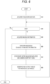
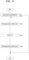
- Fig. 11 illustrates the switching control of the switch units 11 and 12 by the SW controller 10.
- the SW controller 10 proceeds from step S101 to step S102, and performs the switching control of the switch unit 11 by the control signal C1. That is, the switch unit 11 is immediately switched according to the generation of the switching trigger KP.
- the SW controller 10 waits for a predetermined time set as a switching delay time Tdl in step S103.
- the SW controller 10 When the time as the switching delay time Tdl elapsed, the SW controller 10 performs the switching control of the switch unit 12 by the control signal C2 in step S104. That is, in a case where the SW controller 10 causes the switch unit 11 to select the background video vBa in step S102, the SW controller 10 causes the switch unit 12 to select the captured video vCa in step S104. Similarly, in a case where the SW controller 10 causes the switch unit 11 to select the background video vBb in step S102, the SW controller 10 causes the switch unit 12 to select the captured video vCb in step S104.
- the SW controller 10 first causes the switch unit 11 to execute switching of in response to the switching trigger KP, and causes the switch unit 12 to execute switching after the switching delay time Tdl elapses.
- the switching delay time Tdl will be described.
- the switching delay time Tdl is a time corresponding to a time lag, for example, from when the background video vBb for the camera 502b is selected by the switch unit 11 to when the captured video vCb obtained by capturing the background video vBb by the camera 502b is input to the switch unit 12.
- LED-side operation mode As the setting of the operation mode on the LED panel 506 side (hereinafter also referred to as "LED-side operation mode"), there are setting of the frame rate and setting of various types of signal processing performed by the display controller 590 and the LED processor 570, so that a delay time until display switching occurs according to these LED-side operation modes.
- the delay time from the switching of the switch unit 12 to the switching of the display differs depending on the resizing processing of the video according to the LED wall 505 (LED panel 506) side or the like.
- the setting of the operation mode related to imaging by the camera is also related to the time lag.
- the operation mode related to imaging by the camera is an operation mode in the camera 502 or the camera signal processing unit 515.
- the operation mode related to imaging by the camera is also referred to as a "camera-side operation mode". For example, a delay occurs due to a frame rate, a shutter speed, a reading region from the image sensor, processing contents of the camera signal processing unit 515, and the like as settings of the camera 502.
- Fig. 12 illustrates an example of a reading range from an image sensor 30. It is assumed that a solid line indicates the entire pixel region of the image sensor 30. Reading of a photoelectric conversion signal to be an imaging signal from the image sensor 30 may be performed in the entire pixel region indicated by a solid line in some cases, or may be performed in various cases according to a reading mode, such as a range indicated by a dotted line, a range indicated by a broken line, and a range indicated by an alternate long and short dash line. The delay time varies according to the difference between these reading ranges. Furthermore, there is also a delay due to signal processing or resizing processing on the captured video vC.
- a time lag occurs from when the background video vBb displayed on the LED wall 505 is captured (exposed) by the camera 502b until the captured video vCb is input to the switch unit 12.
- the switching delay time Tdl is set according to the LED-side operation mode and the camera-side operation mode.
- the switch unit 12 is switched at the timing when the captured video vCb obtained by capturing the background video vBb by the camera 502b is input to the switch unit 12, and the main line video vCm can be set to the video vCb captured by the camera 502b.
- the switching timing of the switch unit 12 is early, the captured video vCb captured by the camera 502b at the time when the background video vBa is displayed becomes the main line video vCm. This means that the video with the incorrect background is included in the main line video vCm.
- an appropriate switching delay time Tdl is set, and the switching timing is controlled as illustrated in Fig. 11 .
- the switch unit 12 by switching the switch unit 12 at the timing when the background video vB after the switching is input to the switch unit 12, the main line video vCm does not become a video with incorrect background.
- Fig. 10 the case where imaging is performed by the two cameras 502a and 502b is exemplified, but when imaging is performed by three or more cameras 502, the process in Fig. 11 is similarly performed, so that a video with appropriate background can be set as the main line video vCm.
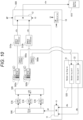
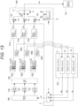
- Fig. 13 illustrates a case where imaging is performed by the three cameras 502a, 502b, and 502c.
- the videos vCa, vCb, and vCc captured by the respective cameras 502 are input to the switch unit 12.
- the background videos vBa, vBb, and vBc are generated by the corresponding rendering units 21,22, and 23, respectively, and are selected by the switch unit 11.
- the SW controller 10 causes the switch unit 12 to execute switching after the switching delay time Tdl elapses.
- the SW controller 10 causes the switch unit 12 to select the captured video vCa in step S104.
- the SW controller 10 causes the switch unit 12 to select the captured video vCb in step S104.
- the SW controller 10 causes the switch unit 12 to select the captured video vCc in step S104.
- step S104 the SW controller 10 performs control to cause the switch unit 12 to execute switching to the video vC captured by the camera 502 corresponding to the background video vB after the switching by the switch unit 11.
- delay buffers 15a, 15b, and 15c are illustrated in the switcher 600.
- the delay time due to the camera-side operation mode is not different among the cameras 502a, 502b, and 502c, for example, in a case where the cameras 502a, 502b, and 502c are of the same model, the delay buffers 15a, 15b, and 15c are usually unnecessary.
- the delay times of the plurality of cameras 502 may be different for some reasons.
- the delay buffers 15a, 15b, and 15c are provided to make the delay times of the captured videos vCa, vCb, and vCc captured by the respective cameras 502 uniform, and the captured videos vCa, vCb, and vCc are input to the switch unit 12.
- the delay buffers 15a, 15b, and 15c provide buffer delay times DTa, DTb, and DTc for the captured videos vCa, vCb, and vCc, respectively.
- t1, t2, and t3 are times from the input (exposure) of light to the image sensor to the input to the switch unit 12 of the captured videos vCa, vCb, and vCc, respectively. Then, it is assumed that the time t3 is the longest.
- the time until the input of the captured videos vCa, vCb, and vCc to the switch unit 12 is made uniform. Then, by setting the switching delay time Tdl described above on the basis of the uniformized time, it is possible to output the main line video vCm with the correct background from the switching time point of the switch unit 12.
- the switch units 11 and 12 are configured in one switcher 600, a switcher having the switch unit 11 and a switcher having the switch unit 12 may be separate devices.
- the SW controller 10 provided in any switcher or in a separate device only needs to be able to control the switching timing of the switch units 11 and 12 by performing the control in Fig. 11 .
- the SW controller 10 stores the switching delay time Tdl as a fixed value.
- the switching delay time Tdl is determined by the LED-side operation mode and the camera-side operation mode, but the LED-side operation mode and the camera-side operation mode are normally not changed during imaging.
- the operator may input a value of the switching delay time Tdl and store the value in the internal memory of the SW controller 10 or the like.
- the operator sets the switching delay time Tdl as initial setting or the like, and inputs the switching delay time Tdl at the preparation stage before imaging.
- the operator sets an appropriate switching delay time Tdl and inputs the switching delay time Tdl at the preparation stage before imaging.
- the operator inputs information of the LED-side operation mode or the camera-side operation mode to be set at the preparation stage of imaging.
- the SW controller 10 can acquire the delay time by inputting the current operation mode by storing the information of the delay time according to the operation mode as table data or the like, and thereby can calculate the switching delay time Tdl.
- a delay management table for managing a delay time corresponding to various operation modes is registered in advance in the switcher 600.
- the delay management table is stored in a memory in the SW controller 10 or a memory provided separately from the SW controller 10 in the switcher 600.
- the SW controller 10 can inquire of the display controller 590, the LED processor 570, and the LED panel 506 about model information and various setting values. Similarly, it is assumed that the SW controller 10 can inquire each camera 502 and the camera signal processing unit 515 about model information and various setting values.
- the SW controller 10 performs the process in Fig. 14 at the time of preparing for imaging.
- step S201 the SW controller 10 acquires information of the model names and the operation modes of the LED panels and the like connected thereto (the display controller 590, the LED processor 570, the LED panel 506) by communication with these LED panels and the like connected thereto.
- step S202 the SW controller 10 obtains the delay time from the signal input to the light emission of the background video vB by referring to the delay management table using the information acquired from the LED panel or the like.
- step S203 the SW controller 10 acquires information of the model names and the operation modes of the connected cameras and the like (the camera 502, the camera signal processing unit 515) by communication with these cameras and the like.
- step S204 the SW controller 10 obtains the delay time from the light reception to the output of the signal of the captured video vC to the switch unit 12 by referring to the delay management table using the information acquired from the camera or the like.
- step S205 the SW controller 10 adds the respective delay times obtained in steps S202 and S204 to set the switching delay time Tdl.
- the switching delay time Tdl is automatically set by the above process, and is used as the switching delay time Tdl in step S103 in Fig. 11 during the subsequent imaging.
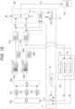
- the configuration illustrated in Fig. 15 is adopted.
- the switcher 600 is provided with a video generator 16 and a video detector 17.
- the video generator 16 can input a video signal for displaying a specific measurement video to the switch unit 11.
- the switch unit 11 selects and outputs the background videos vBa and vBb and the measurement video. Note that the video generator 16 only needs to output a specific measurement video, and only needs to be actually configured by a frame memory that stores a video signal as the measurement video.
- the video detector 17 receives outputs of the camera signal processing units 515a and 515b, that is, the captured videos vCa and vCb, which are video signals input to the switch unit 12, as input, and detects the video contents. Specifically, the video detector 17 only needs to be able to detect at least whether or not the captured videos vCa and vCb are the measurement videos.
- the switcher 600 can output the measurement video, and can detect whether or not the input captured video vC is the measurement video.
- the SW controller 10 performs the process in Fig. 16 , for example, at the time of preparing for imaging.
- step S221 the SW controller 10 causes the LED panel 506 to display the measurement video, for example, as the entire blue. That is, the SW controller 10 causes the video generator 16 to output the measurement video of the entire blue, and causes the switch unit 11 to select the measurement video.
- step S222 the SW controller 10 waits until the input captured video vC becomes the entire blue video. That is, the SW controller 10 waits for the timing at which the video detector 17 detects the captured video vC of the entire blue.
- the SW controller 10 When the video detector 17 detects the captured video vC of the entire blue, the SW controller 10 causes the LED panel 506 to display the measurement video as, for example, the entire red in step S223. That is, the SW controller 10 causes the video generator 16 to output the measurement video of the entire red. The SW controller 10 causes the switch unit 11 to continue the selected state of the measurement video from the video generator 16.
- step S224 the SW controller 10 waits for one frame period to acquire information on the color of the screen detected by the video detector 17, and checks whether the color is blue or red in step S225.
- the SW controller 10 waits for one frame period again, and checks information on the color of the screen detected by the video detector 17.
- the SW controller 10 proceeds to step S226, counts the number of frames until the color is switched from blue to red, and sets the switching delay time Tdl accordingly. For example, in a case where a period of three frames is required for the color being switched from blue to red, the switching delay time Tdl is a time corresponding to three frames.
- the switching delay time Tdl is automatically set by the above process, and is used as the switching delay time Tdl in step S103 in Fig. 11 during the subsequent imaging.
- the video detector 17 may detect the color of the captured video vC of any camera 502.
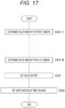
- Fig. 17 illustrates an example of a case where the delay buffers 15a, 15b, and 15c are provided as illustrated in Fig. 13 on the assumption that the delay times of the plurality of cameras 502 are different from each other.
- step S231-1 in Fig. 17 the SW controller 10 performs the processing from step S221 to step S226 in Fig. 16 on the first camera 502.
- the captured video vCa captured is checked by the video detector 17, the number of frames is counted, and the switching delay time Tdl for the camera 502a is calculated.
- Such processing is also performed on the other cameras 502b and 502c.
- Step S231-N indicates that the process in Fig. 16 is similarly performed on the last camera 502 (for example, the camera 502c in the case of three cameras).
- N switching delay times Tdl are calculated by performing the process in Fig. 16 for each of the N cameras.
- step S233 the SW controller 10 sets the delay buffer 15.
- the buffer delay times DTa, DTb, and DTc of the respective delay buffers 15a, 15b, and 15c are set.
- the buffer delay times DTa, DTb, and DTc are set so as to match the delay times from the other cameras 502 with the camera 502 having the longest delay time.
- step S234 the SW controller 10 determines the switching delay time Tdl used in the process in Fig. 11 in consideration of the buffer delay times DTa, DTb, and DTc.
- a value obtained by adding the buffer delay time for the camera 502 to the maximum switching delay time Tdl among the switching delay times Tdl obtained in steps S231-1 to S231-N is set as the switching delay time Tdl to be used.
- the switching delay time Tdl is set by reflecting the buffer delay time.
- the switching delay time Tdl measured for the camera 502 having the maximum delay time is determined to be the switching delay time Tdl to be used.
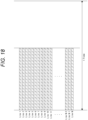
- each camera 502 performs exposure/reading by a global shutter system.
- Fig. 18 schematically illustrates exposure in the global shutter system
- Fig. 19 schematically illustrates exposure in a rolling shutter system.
- a hatched bar indicates an exposure period of each horizontal line.
- Fig. 20 illustrates each period of frames FR0, FR1, FR2, and FR3 displayed on the LED wall 505 as "LED light emission”.
- a state of the exposure and the output of the captured video vC in the camera 502 with the rolling shutter system is schematically illustrated, and a video of one frame is exposed over two preceding and following frames.
- This is not a problem unless switching is particularly performed, but when switching is performed in the switcher 600 in a certain frame, the video content becomes incorrect in the first frame after the switching. That is, the first frame after the switching is mixed with the video of the immediately preceding frame. This means that the videos of the inner frustum vBC not corresponding to the camera 502 for the main line video after switching are mixed.
- a state of the exposure and the output of the captured video vC in the camera 502 with the global shutter system is also schematically illustrated, and, in this case, the exposure of one frame is completed in one frame period. Therefore, even when switching is performed in the switcher 600, different videos before and after the switching are not mixed.
- each camera 502 of the present embodiment uses a camera with the global shutter system.
- a camera with the rolling shutter system is used, if the shutter speed is increased, it is possible to avoid mixing of the images of the preceding and following frames.
- each camera 502 may be a camera capable of switching between the rolling shutter system and the global shutter system.
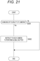
- control device in the imaging system 500 performs the process in Fig. 21 .
- step S301 the control device determines whether or not the imaging system 500 is in a state of performing imaging by the plurality of cameras 502. In the case of imaging by one camera 502, no preliminary control is particularly performed.
- control device when detecting that the plurality of cameras 502 is connected to the imaging system 500 to perform imaging, the control device outputs an instruction to each camera 502 to perform exposure by the global shutter system in step S302.
- control device that performs the process in Fig. 21 only needs to be the information processing device 70 in the imaging system 500, and, for example, to be the rendering engine 520 or the SW controller 10.
- the switcher 600 of the embodiment includes the switch unit 11 (first switch unit) that receives, as video data to be displayed on the LED wall 505 (LED panel 506), a plurality of pieces of video data (for example, background video vBa and vBb) including video content corresponding to each of the plurality of cameras 502 as input, selects one of the plurality of pieces of video data, and outputs the selected video data.
- the switch unit 11 first switch unit
- the switcher 600 includes the switch unit 12 (second switch unit) that receives a plurality of pieces of video data (for example, the captured video vCa, vCb) obtained by capturing the video displayed on the LED wall 505 by the plurality of cameras 502 as input, selects one of the plurality of pieces of video data, and outputs the selected video data. Furthermore, the switcher 600 includes the SW controller 10 that performs control to cause the switch unit 11 to execute switching of the video data in response to the trigger of the video switching, and, after a predetermined switching delay time Tdl elapses, to cause the switch unit 12 to execute switching to the video data by the camera corresponding to the video data after switching in the switch unit 11.
- a predetermined switching delay time Tdl elapses
- the switch unit 11 switches the background video vBa to the background video vBb including the inner frustum vBC of the camera 502b, and the switch unit 12 performs switching to the captured video vC2 when the captured video vC2 is input to the switcher 600.
- the captured video vC2 to be the main line video vCm output from the switch unit 12 becomes a video including the inner frustum vBC correctly corresponding to the camera 502b at this point of time.
- the background videos vBa and vBb corresponding to the plurality of cameras 502 are always rendered, selected by the switcher 600, and supplied to the LED wall 505, the inner frustum vBC does not overlap on the LED wall 505 at the time of imaging by the plurality of cameras. Therefore, the captured video vC is not mixed with the video of the inner frustum vBC of the other camera 502.
- the background videos vBa and vBb corresponding to the respective cameras 502 are always generated and output to the switcher 600. That is, the rendering of the background video vB corresponding to the newly selected camera 502 is not started at the camera switching timing.
- the switching delay time Tdl does not include a rendering delay. Therefore, the switching delay time Tdl does not become long, and the main line video vCm is switched in a short delay time after the trigger of the camera switching.
- Each of the plurality of pieces of video data input to the switch unit 11 of the switcher 600 of the embodiment are the background video vB including the video content rendered according to the position and imaging direction of the corresponding camera 502 with respect to the LED wall 505.
- the background videos vBa and vBb rendered by the rendering units 21 and 22 are input to the switcher 600. That is, the background videos vBa and vBb are images each including the inner frustum vBC rendered according to the positions and imaging directions of the cameras 502a and 502b, respectively. This enables appropriate imaging as a virtual production in which the background is displayed on the LED wall 505 and imaged by the plurality of cameras 502.
- the plurality of pieces of video data input to the switch unit 12 of the embodiment is the captured video vC obtained by capturing the video on the LED wall 505 and the object (the performer 510 and the like) as the foreground by each of the plurality of cameras 502.
- the captured videos vC1 and vC2 obtained by capturing the LED wall 505 and the foreground object with the cameras 502a and 502b are input to the switch unit 12 of the switcher 600, and one of the captured videos vC1 and vC2 is selected as the main line video vCm by the switch unit 12.
- the SW controller 10 sets the switching delay time Tdl on the basis of the LED-side operation mode and the camera-side operation mode.
- the appropriate switching delay time Tdl is a time obtained by adding a time until the background video vB output from the switch unit 11 is displayed on the LED wall 505 and a time until the display is captured by the camera 502 and the captured video vC subjected to the signal processing is input to the switch unit 12. Therefore, these times are calculated from the operation mode regarding the display on the LED wall 505 and the operation mode regarding the imaging and signal processing of the camera 502, and are set as the switching delay time Tdl. As a result, switching of the switch unit 12 at an accurate timing is realized after switching of the switch unit 11.
- the SW controller 10 acquires the LED-side operation mode and the camera-side operation mode by the operation input of the operator.
- an operator or the like inputs information of an operation mode related to the LED wall 505 of the imaging system 500 or an operation mode related to the camera 502, and the SW controller 10 of the switcher 600 performs calculation according to the input to set the switching delay time Tdl.
- the operator or the like inputs the display on the LED wall 505 and the setting state of imaging by the camera 502, whereby the appropriate switching delay time Tdl is set.
- the switcher 600 communicates with the display controller 590, the LED processor 570, or the LED panel 506 to acquire an operation mode related to display on the LED wall 505. Furthermore, the switcher 600 communicates with the camera 502 and the camera signal processing unit 515 to acquire the operation mode information of the camera and the signal processing. As a result, it is possible to automatically set an appropriate switching delay time Tdl by intra-system communication.
- the SW controller 10 sets the switching delay time Tdl on the basis of the measurement of the time until the video output from the switch unit 11 is input to the switch unit 12 (see Fig. 16 ).
- the switcher 600 counting the time until the video actually output from the switch unit 11 is input to the switch unit 12, the delay until the display on the LED wall 505 and the delay time of the video due to the processing of the camera 502 and the like can be known. Therefore, it is possible to set an appropriate switching delay time Tdl on the basis of this measurement.
- the appropriate switching delay time Tdl is always the same.
- the SW controller 10 only needs to store the switching delay time Tdl as a fixed value.
- the switching delay time Tdl is a fixed value
- a plurality of fixed values is stored, and the switching delay time Tdl can be switched by an operation input. As a result, it is possible to cope with a change in system settings and the like.
- the captured videos vC1, vC2, and vC3 are input to the switch unit 12 via the delay buffers 15a, 15b, and 15c, respectively.
- the input timings to the switch unit 12 can be made simultaneously by the buffer delay times DTa, DTb, and DTc in the delay buffers 15a, 15b, and 15c. That is, even in a case where the appropriate switching delay time Tdl is different in each camera 502 due to different models of cameras or the like, switching can be performed at an appropriate timing by aligning the delay times by the delay buffers 15a, 15b, and 15c.
- the buffer delay times DTa, DTb, and DTc may be a part of the switching delay time Tdl. Therefore, by setting the switching delay time Tdl according to the settings of the buffer delay times DTa, DTb, and DTc, the switching of the switch unit 12 is performed at an accurate timing.
- Each of the plurality of cameras 502 of the embodiment is a camera that performs exposure by the global shutter system.
- the control device such as the SW controller 10 instructs the switchable camera to perform exposure of the global shutter system (see Fig. 21 ).
- control is performed such that imaging is executed by the global shutter system.
- a camera capable of switching between the exposure of the global shutter system and the exposure of the rolling shutter system is used, it is possible to prevent videos between the preceding and following frames from being mixed at the time of switching of the switch unit 12.
- a program of the embodiments is a program for causing a processor, for example, a CPU, a DSP, or the like, or a device including the processor to execute the process as illustrated in Figs. 11 , 14 , 16 , and 17 described above.
- the program of the embodiment is a program for causing the information processing device 70 to execute processing of causing the switch unit 11 to execute switching of the video data in response to the trigger of the video switching, and, after the predetermined switching delay time Tdl elapses, causing the switch unit 12 to execute switching to the video data by the camera 502 corresponding to the video data after the switching in the switch unit 11.
- the program is a program to be executed by the SW controller 10 of the switcher 600.
- the information processing device 70 that executes the above-described correction processing can be implemented by various computer apparatuses.
- Such a program can be recorded in advance in an HDD as a recording medium built in a device such as a computer device, a ROM in a microcomputer having a CPU, or the like. Furthermore, such a program can be temporarily or permanently stored (recorded) in a removable recording medium such as a flexible disk, a compact disc read only memory (CD-ROM), a magneto optical (MO) disk, a digital versatile disc (DVD), a Blu-ray Disc (registered trademark), a magnetic disk, a semiconductor memory, or a memory card.
- a removable recording medium can be provided as what is called package software.
- Such a program can be installed from the removable recording medium into a personal computer and the like, or can be downloaded from a download site through a network such as a local area network (LAN) or the Internet.
- LAN local area network
- Such a program is suitable for providing the information processing device 70 and the switcher 600 of the embodiment in a wide range.
- a program is suitable for providing the information processing device 70 and the switcher 600 of the embodiment in a wide range.
- a personal computer a communication device
- a portable terminal device such as a smartphone or a tablet
- a mobile phone a game device
- a video device a personal digital assistant (PDA)
- PDA personal digital assistant
Landscapes
- Engineering & Computer Science (AREA)
- Multimedia (AREA)
- Signal Processing (AREA)
- Theoretical Computer Science (AREA)
- Human Computer Interaction (AREA)
- Physics & Mathematics (AREA)
- General Engineering & Computer Science (AREA)
- General Physics & Mathematics (AREA)
- Studio Devices (AREA)
Applications Claiming Priority (2)
| Application Number | Priority Date | Filing Date | Title |
|---|---|---|---|
| JP2022083040 | 2022-05-20 | ||
| PCT/JP2023/015647 WO2023223758A1 (ja) | 2022-05-20 | 2023-04-19 | スイッチャー装置、制御方法、撮影システム |
Publications (2)
| Publication Number | Publication Date |
|---|---|
| EP4529152A1 true EP4529152A1 (de) | 2025-03-26 |
| EP4529152A4 EP4529152A4 (de) | 2025-08-20 |
Family
ID=88834968
Family Applications (1)
| Application Number | Title | Priority Date | Filing Date |
|---|---|---|---|
| EP23807370.4A Pending EP4529152A4 (de) | 2022-05-20 | 2023-04-19 | Schaltervorrichtung, steuerungsverfahren und bildgebungssystem |
Country Status (5)
| Country | Link |
|---|---|
| US (1) | US20250301100A1 (de) |
| EP (1) | EP4529152A4 (de) |
| JP (1) | JPWO2023223758A1 (de) |
| CN (1) | CN119183658A (de) |
| WO (1) | WO2023223758A1 (de) |
Family Cites Families (7)
| Publication number | Priority date | Publication date | Assignee | Title |
|---|---|---|---|---|
| JP4505559B2 (ja) * | 2000-12-26 | 2010-07-21 | 株式会社Tbsテレビ | スタジオセット用遠見パネルおよびこれを用いたスタジオセット |
| JP4039610B2 (ja) * | 2002-04-04 | 2008-01-30 | 日本放送協会 | 画像合成装置およびその方法ならびに画像表示装置およびその方法 |
| GB2437575A (en) * | 2006-04-27 | 2007-10-31 | Andrew Peter Phelan | Audience-specific image display |
| JP2008092120A (ja) * | 2006-09-29 | 2008-04-17 | Fujifilm Corp | 画像合成システム |
| EP3355586A1 (de) * | 2017-01-27 | 2018-08-01 | LANE GmbH | Verfahren und system zur übertragung von alternativem bildinhalt einer physikalischen anzeige an unterschiedliche zuschauer |
| CN112689992B (zh) * | 2018-09-13 | 2023-04-14 | 阿帕里奥全球咨询股份有限公司 | 使数码摄影相机与物理显示器上所示的替换图像内容同步的方法和装置 |
| GB2593833B (en) | 2018-11-06 | 2022-09-14 | Lucasfilm Entertainment Co Ltd | Immersive content production system |
-
2023
- 2023-04-19 JP JP2024521626A patent/JPWO2023223758A1/ja active Pending
- 2023-04-19 US US18/861,600 patent/US20250301100A1/en active Pending
- 2023-04-19 EP EP23807370.4A patent/EP4529152A4/de active Pending
- 2023-04-19 WO PCT/JP2023/015647 patent/WO2023223758A1/ja not_active Ceased
- 2023-04-19 CN CN202380040143.2A patent/CN119183658A/zh active Pending
Also Published As
| Publication number | Publication date |
|---|---|
| JPWO2023223758A1 (de) | 2023-11-23 |
| US20250301100A1 (en) | 2025-09-25 |
| CN119183658A (zh) | 2024-12-24 |
| WO2023223758A1 (ja) | 2023-11-23 |
| EP4529152A4 (de) | 2025-08-20 |
Similar Documents
| Publication | Publication Date | Title |
|---|---|---|
| EP4380143A1 (de) | Informationsverarbeitungsvorrichtung, videoverarbeitungsverfahren und programm | |
| EP4539448A1 (de) | Informationsverarbeitungsvorrichtung, informationsverarbeitungsverfahren, programm und informationsverarbeitungssystem | |
| US20240406338A1 (en) | Information processing device, video processing method, and program | |
| EP4407977A1 (de) | Informationsverarbeitungsvorrichtung, bildverarbeitungsverfahren und programm | |
| JP7632405B2 (ja) | 情報処理装置、情報処理方法、プログラム | |
| EP4496303A1 (de) | Informationsverarbeitungsvorrichtung, informationsverarbeitungsverfahren und programm | |
| EP4583504A1 (de) | Informationsverarbeitungsvorrichtung, informationsverarbeitungsverfahren und programm | |
| EP4407974A1 (de) | Informationsverarbeitungsvorrichtung, bildverarbeitungsverfahren und programm | |
| EP4529152A1 (de) | Schaltervorrichtung, steuerungsverfahren und bildgebungssystem | |
| US20240414290A1 (en) | Information processing device and information processing method | |
| EP4529202A1 (de) | Informationsverarbeitungsvorrichtung, informationsverarbeitungsverfahren und bildgebungssystem | |
| JP2024098589A (ja) | 撮像装置、プログラム | |
| EP4601283A1 (de) | Informationsverarbeitungsvorrichtung und -programm | |
| WO2025177810A1 (ja) | 情報処理装置、および情報処理方法、並びにプログラム | |
| WO2025084116A1 (ja) | 情報処理装置、情報処理システム、情報処理方法 |
Legal Events
| Date | Code | Title | Description |
|---|---|---|---|
| STAA | Information on the status of an ep patent application or granted ep patent |
Free format text: STATUS: THE INTERNATIONAL PUBLICATION HAS BEEN MADE |
|
| PUAI | Public reference made under article 153(3) epc to a published international application that has entered the european phase |
Free format text: ORIGINAL CODE: 0009012 |
|
| STAA | Information on the status of an ep patent application or granted ep patent |
Free format text: STATUS: REQUEST FOR EXAMINATION WAS MADE |
|
| 17P | Request for examination filed |
Effective date: 20241129 |
|
| AK | Designated contracting states |
Kind code of ref document: A1 Designated state(s): AL AT BE BG CH CY CZ DE DK EE ES FI FR GB GR HR HU IE IS IT LI LT LU LV MC ME MK MT NL NO PL PT RO RS SE SI SK SM TR |
|
| RAP3 | Party data changed (applicant data changed or rights of an application transferred) |
Owner name: SONY GROUP CORPORATION |
|
| A4 | Supplementary search report drawn up and despatched |
Effective date: 20250722 |
|
| RIC1 | Information provided on ipc code assigned before grant |
Ipc: H04N 5/222 20060101AFI20250716BHEP Ipc: H04N 5/268 20060101ALI20250716BHEP Ipc: H04N 23/667 20230101ALI20250716BHEP Ipc: H04N 23/90 20230101ALI20250716BHEP Ipc: G06F 3/14 20060101ALI20250716BHEP Ipc: G09F 9/302 20060101ALI20250716BHEP Ipc: G09F 9/33 20060101ALI20250716BHEP Ipc: H04N 5/265 20060101ALI20250716BHEP |
|
| DAV | Request for validation of the european patent (deleted) | ||
| DAX | Request for extension of the european patent (deleted) |