EP4528757A1 - Insulated covered soft magnetic metal powder, magnetic dust core, electronic element, electronic device, electric motor and power generator - Google Patents
Insulated covered soft magnetic metal powder, magnetic dust core, electronic element, electronic device, electric motor and power generator Download PDFInfo
- Publication number
- EP4528757A1 EP4528757A1 EP23807433.0A EP23807433A EP4528757A1 EP 4528757 A1 EP4528757 A1 EP 4528757A1 EP 23807433 A EP23807433 A EP 23807433A EP 4528757 A1 EP4528757 A1 EP 4528757A1
- Authority
- EP
- European Patent Office
- Prior art keywords
- soft magnetic
- magnetic metal
- dust core
- peak
- metal powder
- Prior art date
- Legal status (The legal status is an assumption and is not a legal conclusion. Google has not performed a legal analysis and makes no representation as to the accuracy of the status listed.)
- Pending
Links
Images






Classifications
-
- B—PERFORMING OPERATIONS; TRANSPORTING
- B22—CASTING; POWDER METALLURGY
- B22F—WORKING METALLIC POWDER; MANUFACTURE OF ARTICLES FROM METALLIC POWDER; MAKING METALLIC POWDER; APPARATUS OR DEVICES SPECIALLY ADAPTED FOR METALLIC POWDER
- B22F1/00—Metallic powder; Treatment of metallic powder, e.g. to facilitate working or to improve properties
- B22F1/05—Metallic powder characterised by the size or surface area of the particles
-
- B—PERFORMING OPERATIONS; TRANSPORTING
- B22—CASTING; POWDER METALLURGY
- B22F—WORKING METALLIC POWDER; MANUFACTURE OF ARTICLES FROM METALLIC POWDER; MAKING METALLIC POWDER; APPARATUS OR DEVICES SPECIALLY ADAPTED FOR METALLIC POWDER
- B22F1/00—Metallic powder; Treatment of metallic powder, e.g. to facilitate working or to improve properties
- B22F1/14—Treatment of metallic powder
- B22F1/142—Thermal or thermo-mechanical treatment
-
- B—PERFORMING OPERATIONS; TRANSPORTING
- B22—CASTING; POWDER METALLURGY
- B22F—WORKING METALLIC POWDER; MANUFACTURE OF ARTICLES FROM METALLIC POWDER; MAKING METALLIC POWDER; APPARATUS OR DEVICES SPECIALLY ADAPTED FOR METALLIC POWDER
- B22F1/00—Metallic powder; Treatment of metallic powder, e.g. to facilitate working or to improve properties
- B22F1/14—Treatment of metallic powder
- B22F1/145—Chemical treatment, e.g. passivation or decarburisation
-
- B—PERFORMING OPERATIONS; TRANSPORTING
- B22—CASTING; POWDER METALLURGY
- B22F—WORKING METALLIC POWDER; MANUFACTURE OF ARTICLES FROM METALLIC POWDER; MAKING METALLIC POWDER; APPARATUS OR DEVICES SPECIALLY ADAPTED FOR METALLIC POWDER
- B22F1/00—Metallic powder; Treatment of metallic powder, e.g. to facilitate working or to improve properties
- B22F1/16—Metallic particles coated with a non-metal
-
- B—PERFORMING OPERATIONS; TRANSPORTING
- B22—CASTING; POWDER METALLURGY
- B22F—WORKING METALLIC POWDER; MANUFACTURE OF ARTICLES FROM METALLIC POWDER; MAKING METALLIC POWDER; APPARATUS OR DEVICES SPECIALLY ADAPTED FOR METALLIC POWDER
- B22F1/00—Metallic powder; Treatment of metallic powder, e.g. to facilitate working or to improve properties
- B22F1/17—Metallic particles coated with metal
-
- B—PERFORMING OPERATIONS; TRANSPORTING
- B22—CASTING; POWDER METALLURGY
- B22F—WORKING METALLIC POWDER; MANUFACTURE OF ARTICLES FROM METALLIC POWDER; MAKING METALLIC POWDER; APPARATUS OR DEVICES SPECIALLY ADAPTED FOR METALLIC POWDER
- B22F3/00—Manufacture of workpieces or articles from metallic powder characterised by the manner of compacting or sintering; Apparatus specially adapted therefor ; Presses and furnaces
- B22F3/02—Compacting only
-
- B—PERFORMING OPERATIONS; TRANSPORTING
- B22—CASTING; POWDER METALLURGY
- B22F—WORKING METALLIC POWDER; MANUFACTURE OF ARTICLES FROM METALLIC POWDER; MAKING METALLIC POWDER; APPARATUS OR DEVICES SPECIALLY ADAPTED FOR METALLIC POWDER
- B22F3/00—Manufacture of workpieces or articles from metallic powder characterised by the manner of compacting or sintering; Apparatus specially adapted therefor ; Presses and furnaces
- B22F3/02—Compacting only
- B22F3/03—Press-moulding apparatus therefor
-
- B—PERFORMING OPERATIONS; TRANSPORTING
- B22—CASTING; POWDER METALLURGY
- B22F—WORKING METALLIC POWDER; MANUFACTURE OF ARTICLES FROM METALLIC POWDER; MAKING METALLIC POWDER; APPARATUS OR DEVICES SPECIALLY ADAPTED FOR METALLIC POWDER
- B22F3/00—Manufacture of workpieces or articles from metallic powder characterised by the manner of compacting or sintering; Apparatus specially adapted therefor ; Presses and furnaces
- B22F3/24—After-treatment of workpieces or articles
-
- B—PERFORMING OPERATIONS; TRANSPORTING
- B22—CASTING; POWDER METALLURGY
- B22F—WORKING METALLIC POWDER; MANUFACTURE OF ARTICLES FROM METALLIC POWDER; MAKING METALLIC POWDER; APPARATUS OR DEVICES SPECIALLY ADAPTED FOR METALLIC POWDER
- B22F5/00—Manufacture of workpieces or articles from metallic powder characterised by the special shape of the product
- B22F5/10—Manufacture of workpieces or articles from metallic powder characterised by the special shape of the product of articles with cavities or holes, not otherwise provided for in the preceding subgroups
- B22F5/106—Tube or ring forms
-
- C—CHEMISTRY; METALLURGY
- C22—METALLURGY; FERROUS OR NON-FERROUS ALLOYS; TREATMENT OF ALLOYS OR NON-FERROUS METALS
- C22C—ALLOYS
- C22C38/00—Ferrous alloys, e.g. steel alloys
-
- C—CHEMISTRY; METALLURGY
- C22—METALLURGY; FERROUS OR NON-FERROUS ALLOYS; TREATMENT OF ALLOYS OR NON-FERROUS METALS
- C22C—ALLOYS
- C22C38/00—Ferrous alloys, e.g. steel alloys
- C22C38/02—Ferrous alloys, e.g. steel alloys containing silicon
-
- H—ELECTRICITY
- H01—ELECTRIC ELEMENTS
- H01F—MAGNETS; INDUCTANCES; TRANSFORMERS; SELECTION OF MATERIALS FOR THEIR MAGNETIC PROPERTIES
- H01F1/00—Magnets or magnetic bodies characterised by the magnetic materials therefor; Selection of materials for their magnetic properties
- H01F1/01—Magnets or magnetic bodies characterised by the magnetic materials therefor; Selection of materials for their magnetic properties of inorganic materials
- H01F1/03—Magnets or magnetic bodies characterised by the magnetic materials therefor; Selection of materials for their magnetic properties of inorganic materials characterised by their coercivity
- H01F1/12—Magnets or magnetic bodies characterised by the magnetic materials therefor; Selection of materials for their magnetic properties of inorganic materials characterised by their coercivity of soft-magnetic materials
- H01F1/14—Magnets or magnetic bodies characterised by the magnetic materials therefor; Selection of materials for their magnetic properties of inorganic materials characterised by their coercivity of soft-magnetic materials metals or alloys
- H01F1/20—Magnets or magnetic bodies characterised by the magnetic materials therefor; Selection of materials for their magnetic properties of inorganic materials characterised by their coercivity of soft-magnetic materials metals or alloys in the form of particles, e.g. powder
- H01F1/22—Magnets or magnetic bodies characterised by the magnetic materials therefor; Selection of materials for their magnetic properties of inorganic materials characterised by their coercivity of soft-magnetic materials metals or alloys in the form of particles, e.g. powder pressed, sintered, or bound together
- H01F1/24—Magnets or magnetic bodies characterised by the magnetic materials therefor; Selection of materials for their magnetic properties of inorganic materials characterised by their coercivity of soft-magnetic materials metals or alloys in the form of particles, e.g. powder pressed, sintered, or bound together the particles being insulated
-
- H—ELECTRICITY
- H01—ELECTRIC ELEMENTS
- H01F—MAGNETS; INDUCTANCES; TRANSFORMERS; SELECTION OF MATERIALS FOR THEIR MAGNETIC PROPERTIES
- H01F1/00—Magnets or magnetic bodies characterised by the magnetic materials therefor; Selection of materials for their magnetic properties
- H01F1/01—Magnets or magnetic bodies characterised by the magnetic materials therefor; Selection of materials for their magnetic properties of inorganic materials
- H01F1/03—Magnets or magnetic bodies characterised by the magnetic materials therefor; Selection of materials for their magnetic properties of inorganic materials characterised by their coercivity
- H01F1/12—Magnets or magnetic bodies characterised by the magnetic materials therefor; Selection of materials for their magnetic properties of inorganic materials characterised by their coercivity of soft-magnetic materials
- H01F1/33—Magnets or magnetic bodies characterised by the magnetic materials therefor; Selection of materials for their magnetic properties of inorganic materials characterised by their coercivity of soft-magnetic materials mixtures of metallic and non-metallic particles; metallic particles having oxide skin
-
- H—ELECTRICITY
- H01—ELECTRIC ELEMENTS
- H01F—MAGNETS; INDUCTANCES; TRANSFORMERS; SELECTION OF MATERIALS FOR THEIR MAGNETIC PROPERTIES
- H01F27/00—Details of transformers or inductances, in general
- H01F27/24—Magnetic cores
- H01F27/255—Magnetic cores made from particles
-
- H—ELECTRICITY
- H01—ELECTRIC ELEMENTS
- H01F—MAGNETS; INDUCTANCES; TRANSFORMERS; SELECTION OF MATERIALS FOR THEIR MAGNETIC PROPERTIES
- H01F3/00—Cores, Yokes, or armatures
- H01F3/08—Cores, Yokes, or armatures made from powder
-
- H—ELECTRICITY
- H02—GENERATION; CONVERSION OR DISTRIBUTION OF ELECTRIC POWER
- H02K—DYNAMO-ELECTRIC MACHINES
- H02K1/00—Details of the magnetic circuit
- H02K1/02—Details of the magnetic circuit characterised by the magnetic material
-
- B—PERFORMING OPERATIONS; TRANSPORTING
- B22—CASTING; POWDER METALLURGY
- B22F—WORKING METALLIC POWDER; MANUFACTURE OF ARTICLES FROM METALLIC POWDER; MAKING METALLIC POWDER; APPARATUS OR DEVICES SPECIALLY ADAPTED FOR METALLIC POWDER
- B22F3/00—Manufacture of workpieces or articles from metallic powder characterised by the manner of compacting or sintering; Apparatus specially adapted therefor ; Presses and furnaces
- B22F3/24—After-treatment of workpieces or articles
- B22F2003/248—Thermal after-treatment
-
- B—PERFORMING OPERATIONS; TRANSPORTING
- B22—CASTING; POWDER METALLURGY
- B22F—WORKING METALLIC POWDER; MANUFACTURE OF ARTICLES FROM METALLIC POWDER; MAKING METALLIC POWDER; APPARATUS OR DEVICES SPECIALLY ADAPTED FOR METALLIC POWDER
- B22F2201/00—Treatment under specific atmosphere
- B22F2201/02—Nitrogen
-
- B—PERFORMING OPERATIONS; TRANSPORTING
- B22—CASTING; POWDER METALLURGY
- B22F—WORKING METALLIC POWDER; MANUFACTURE OF ARTICLES FROM METALLIC POWDER; MAKING METALLIC POWDER; APPARATUS OR DEVICES SPECIALLY ADAPTED FOR METALLIC POWDER
- B22F2301/00—Metallic composition of the powder or its coating
- B22F2301/35—Iron
-
- B—PERFORMING OPERATIONS; TRANSPORTING
- B22—CASTING; POWDER METALLURGY
- B22F—WORKING METALLIC POWDER; MANUFACTURE OF ARTICLES FROM METALLIC POWDER; MAKING METALLIC POWDER; APPARATUS OR DEVICES SPECIALLY ADAPTED FOR METALLIC POWDER
- B22F2302/00—Metal Compound, non-Metallic compound or non-metal composition of the powder or its coating
- B22F2302/25—Oxide
-
- B—PERFORMING OPERATIONS; TRANSPORTING
- B22—CASTING; POWDER METALLURGY
- B22F—WORKING METALLIC POWDER; MANUFACTURE OF ARTICLES FROM METALLIC POWDER; MAKING METALLIC POWDER; APPARATUS OR DEVICES SPECIALLY ADAPTED FOR METALLIC POWDER
- B22F2304/00—Physical aspects of the powder
- B22F2304/10—Micron size particles, i.e. above 1 micrometer up to 500 micrometer
-
- B—PERFORMING OPERATIONS; TRANSPORTING
- B22—CASTING; POWDER METALLURGY
- B22F—WORKING METALLIC POWDER; MANUFACTURE OF ARTICLES FROM METALLIC POWDER; MAKING METALLIC POWDER; APPARATUS OR DEVICES SPECIALLY ADAPTED FOR METALLIC POWDER
- B22F2998/00—Supplementary information concerning processes or compositions relating to powder metallurgy
- B22F2998/10—Processes characterised by the sequence of their steps
-
- B—PERFORMING OPERATIONS; TRANSPORTING
- B22—CASTING; POWDER METALLURGY
- B22F—WORKING METALLIC POWDER; MANUFACTURE OF ARTICLES FROM METALLIC POWDER; MAKING METALLIC POWDER; APPARATUS OR DEVICES SPECIALLY ADAPTED FOR METALLIC POWDER
- B22F2999/00—Aspects linked to processes or compositions used in powder metallurgy
-
- C—CHEMISTRY; METALLURGY
- C22—METALLURGY; FERROUS OR NON-FERROUS ALLOYS; TREATMENT OF ALLOYS OR NON-FERROUS METALS
- C22C—ALLOYS
- C22C1/00—Making non-ferrous alloys
- C22C1/04—Making non-ferrous alloys by powder metallurgy
- C22C1/0433—Nickel- or cobalt-based alloys
-
- C—CHEMISTRY; METALLURGY
- C22—METALLURGY; FERROUS OR NON-FERROUS ALLOYS; TREATMENT OF ALLOYS OR NON-FERROUS METALS
- C22C—ALLOYS
- C22C2202/00—Physical properties
- C22C2202/02—Magnetic
-
- C—CHEMISTRY; METALLURGY
- C22—METALLURGY; FERROUS OR NON-FERROUS ALLOYS; TREATMENT OF ALLOYS OR NON-FERROUS METALS
- C22C—ALLOYS
- C22C33/00—Making ferrous alloys
- C22C33/02—Making ferrous alloys by powder metallurgy
Definitions
- the present disclosure relates to an insulation-coated soft magnetic metal powder, a dust core, an electronic element, an electronic device, an electric motor, and a generator.
- Patent Document 1 discloses ferromagnetic powder for a dust core in which 0.1 to 10 vol% of a ZrO 2 sol is added to an atomized iron powder.
- Patent Document 2 describes an insulation-coated soft magnetic metal powder in which zirconium oxide is used.
- the present disclosure has been made in view of the above circumstances.
- An object of the present disclosure is to achieve loss reduction of an insulation-coated soft magnetic metal powder.
- the present disclosure can be realized in the following form.
- loss reduction of the insulation-coated soft magnetic metal powder can be achieved.
- An insulation-coated soft magnetic metal powder 1 includes: soft magnetic metal particles 2 having an average equivalent circle diameter of 10 ⁇ m to 100 ⁇ m; and an insulation layer 3 formed on a surface of each of the soft magnetic metal particles 2.
- the insulation layer 3 contains an oxide including Zr element.
- the oxide is measured at 25°C by XRD (X-ray diffraction)
- the strongest peak is a cubic peak or a tetragonal peak, and the intensity of a monoclinic peak is not greater than one-tenth of the intensity of the strongest peak.
- the soft magnetic metal particles 2 are not limited in particular as long as they are metal particles being soft magnetic, and a wide range of such metal particles can be used.
- the soft magnetic metal particles 2 a wide range of particles, such as those of pure iron and those of an iron-based alloy that are soft magnetic, can be used.
- an iron-based alloy an Fe-Si alloy, an Fe-Si-Cr alloy, an Fe-Si-Al alloy (sendust), an Ni-Fe alloy (permalloy), an Ni-Fe-Mo alloy (supermalloy), an Fe-based amorphous alloy, an Fe-Co alloy, or the like can be appropriately used.
- an Fe-Si alloy, an Fe-Si-Cr alloy, an Fe-Si-Al alloy (sendust), an Ni-Fe alloy (permalloy), and an Ni-Fe-Mo alloy (supermalloy) are preferable from the viewpoint of magnetic permeability, coercive force, and frequency characteristics.
- an alloy having a composition composed of, for example, 0.1 mass% to 10 mass% of Si, and Fe and inevitable impurities as the remainder, can be used.
- an alloy having a composition composed of, for example, 0.1 mass% to 10 mass% of Si, 10 mass% to 20 mass% of Cr, and Fe and inevitable impurities as the remainder, can be used.
- the average equivalent circle diameter of the soft magnetic metal particles 2 is 10 ⁇ m or more and 100 ⁇ m or less, preferably 25 ⁇ m or more and 100 ⁇ m or less, and more preferably 50 ⁇ m or more and 100 m or less.
- the average equivalent circle diameter of the soft magnetic metal particles 2 can be changed as appropriate depending on the frequency band that is used. In particular, when it is assumed to be used in a high frequency band exceeding 100 kHz, the average equivalent circle diameter is more preferably 10 ⁇ m or more and 25 ⁇ m or less.
- the average equivalent circle diameter of the soft magnetic metal particles 2 can be obtained by calculating an area-equivalent circle diameter from each particle area obtained through observation of a cross section by an FE-SEM.
- an area-equivalent circle diameter is calculated from each particle area obtained through observation of a cross section of the dust core 10 by an FE-SEM, and the area-equivalent circle diameter is used for the average equivalent circle diameter. More specifically, the average equivalent circle diameter is obtained as follows.
- a predetermined observation field of view e.g. 200 ⁇ m ⁇ 200 ⁇ m
- multiple soft magnetic metal particles 2 that can be observed without missing parts are focused on.
- the diameter of an ideal circle (perfect circle) having an area equal to the area (projected area) of each particle image of the soft magnetic metal particles 2 is calculated as an equivalent circle diameter of each particle.
- the respective equivalent circle diameters of the particles are arithmetically averaged, whereby the average equivalent circle diameter is obtained.
- the equivalent circle diameter of each particle and the average equivalent circle diameter can be obtained by using general image analysis software.
- the average equivalent circle diameter of the particles forming the insulation layer 3 is not limited in particular. From the viewpoint of reducing eddy current loss, the average equivalent circle diameter of the particles forming the insulation layer 3 is preferably 20 nm or more and 50 nm or less. The average equivalent circle diameter of the particles forming the insulation layer 3 can be controlled by adjusting the particle diameter of the raw material of the insulation layer 3.
- the above oxide may be stabilized zirconia or partially stabilized zirconia that contains calcia (CaO).
- the amount of magnesia in stabilized zirconia or partially stabilized zirconia is preferably 4 mol% or more, more preferably 7 mol% or more, and further preferably 10 mol% or more.
- the amount of magnesia in stabilized zirconia or partially stabilized zirconia is preferably 20 mol% or less.
- the amount of magnesia in stabilized zirconia or partially stabilized zirconia is preferably 4 mol% or more and 20 mol% or less, and more preferably 7 mol% or more and 20 mol% or less.
- peaks derived from the soft magnetic metal particles 2, a measurement cell, etc. are excluded, and a peak derived from the oxide including Zr element is obtained.
- the peak is specified as the strongest peak.
- the peak having the highest intensity out of the multiple peaks is specified as the strongest peak.
- the reason why loss can be reduced in the insulation-coated soft magnetic metal powder 1 (the dust core 10) is not certain, but can be inferred as follows.
- the heat treatment condition is changed as appropriate according to the types of the soft magnetic metal powder and the oxide that are used.
- a reactor 50 shown in Fig. 9 is an example of the electronic element of the present disclosure.
- the reactor 50 includes a dust core 51 and a coil 53.
- the dust core 51 has a configuration similar to that of the dust core 10.
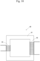
- a transformer 60 shown in Fig. 10 is an example of the electronic element of the present disclosure.
- the transformer 60 includes a dust core 61 and a pair of coils 63, 65.
- the dust core 61 has a configuration similar to that of the dust core 10 above.
- the dust core 10 above is suitably used in an electronic device.
- the electronic device includes an electronic element.
- Examples of the electronic element include the electronic elements described above.
- the dust core 10 above is suitably used in an electric motor.
- the electric motor include a motor, a linear actuator, and the like.
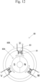
- a motor 80 shown in Fig. 12 is an example of an electric motor of the present disclosure.
- the motor 80 includes a rotor 80A and a stator 80B.
- the stator 80B has a dust core 81 and a coil 83.
- the dust core 81 has a configuration similar to that of the dust core 10 above.
- a generator 90 shown in Fig. 13 is an example of a generator of the present disclosure.
- the generator 90 includes a rotor 90A and a stator 90B.
- the stator 90B has a dust core 91 and a coil 93.
- the dust core 91 has a configuration similar to that of the dust core 10 above.
- a suspension including zirconia particles, yttrium acetate, a small amount of an organic component, and a solvent was mixed with pure iron particles, and the mixture was dried and subjected to heat treatment.
- the concentration of oxide particles in the suspension was set to 0.1 mass% to 2 mass% with respect to the entire suspension.
- the amount of the suspension that was mixed with soft magnetic metal particles was set such that the entire amount of the contained oxide particles was 6 volume% with respect to the soft magnetic metal particles.
- the amount of yttrium acetate was set such that Zr element was 84 mol% and Y element was 16 mol% (8 mol% in terms of Y 2 O 3 ).
- the conditions of the heat treatment (first heat treatment) were a heat treatment temperature of 900°C and in nitrogen. The heat treatment was performed for the purpose of removing the organic component in the insulation layer and advancing solid solution reaction of the oxide. In this manner, an insulation-coated soft magnetic metal powder of Example 1 was obtained.
- the obtained insulation-coated soft magnetic metal powder was put in a mold and subjected to press molding at a molding pressure of 1.7 GPa, whereby a press molded body having a diameter of 10 mm or a toroidal shape (outer diameter: 8 mm, inner diameter: 4.5 mm, height: 1.5 mm) was obtained.
- This molded body was subjected to heat treatment (second heat treatment).
- the conditions of the heat treatment were a heat treatment temperature of 600°C to 1200°C, a temperature increase rate in a range of 350°C to 600°C of 3°C/min to 10°C/min, and in nitrogen. In this manner, a dust core of Example 1 was obtained.
- a dust core of Example 2 was obtained in the same manner as that in Example 1 except that Fe-3.5 mass% Si alloy particles were used instead of the pure iron particles.
- a dust core of Comparative Example 1 was obtained in the same manner as that in Example 1 except that yttrium acetate was not added.
- a dust core of Comparative Example 2 was obtained in the same manner as that in Example 2 except that yttrium acetate was not added.
- Table 1 collectively shows characteristics of the soft magnetic metal particles, the insulation layer, and the eddy current loss of Examples and Comparative Examples.
- the column of "Crystal phase of strongest peak” indicates the crystal phase of the strongest peak specified by the method described in the embodiment.
- the intensity of the monoclinic peak is not greater than one-tenth of the intensity of the strongest peak.
- the intensity of the monoclinic peak is greater than one-tenth of the intensity of the strongest peak.
- Crystal phase of strongest peak is cubic or tetragonal, and "Intensity of monoclinic peak relative to intensity of strongest peak” is not greater than 1/10.
- Crystal phase of strongest peak is not cubic or tetragonal, or "Intensity of monoclinic peak relative to intensity of strongest peak” is greater than 1/10.
- Soft magnetic metal particle Insulation layer Eddy current loss (kW/m 3 ) Composition Crystal phase of strongest peak Intensity of monoclinic peak relative to intensity of strongest peak Satisfaction of requirement about intensity of monoclinic peak
- Eddy current loss (kW/m 3 ) of the obtained dust core was measured under conditions of a frequency of 10 kHz and a magnetic flux density of 0.1 T. The measurement results are also shown in Table 1.
- Examples 1, 2 satisfy requirements (a), (b), (c), (d) below.
- Comparative Examples 1, 2 do not satisfy requirement (d).
- Example 1 in which the composition of the soft magnetic metal particles was pure iron, had a low eddy current loss as compared with that of Comparative Example 1 having the same composition.
- Example 2 in which the composition of the soft magnetic metal particles was an Fe-3.5 mass% Si alloy, had a low eddy current loss as compared with that of Comparative Example 2 having the same composition. From these results, it was suggested that the composition of the soft magnetic metal particles is not limited in particular and that a wide range of the soft magnetic metal particles is applicable.
- loss reduction of the insulation-coated soft magnetic metal powder can be achieved.
- the dust core of the present disclosure is particularly suitably used for usages as a motor, a transformer, a reactor, an inductor, a noise filter, and the like.
Landscapes
- Engineering & Computer Science (AREA)
- Chemical & Material Sciences (AREA)
- Power Engineering (AREA)
- Mechanical Engineering (AREA)
- Manufacturing & Machinery (AREA)
- Metallurgy (AREA)
- Materials Engineering (AREA)
- Organic Chemistry (AREA)
- Dispersion Chemistry (AREA)
- Physics & Mathematics (AREA)
- Thermal Sciences (AREA)
- Chemical Kinetics & Catalysis (AREA)
- General Chemical & Material Sciences (AREA)
- Soft Magnetic Materials (AREA)
- Powder Metallurgy (AREA)
Abstract
Description
- The present disclosure relates to an insulation-coated soft magnetic metal powder, a dust core, an electronic element, an electronic device, an electric motor, and a generator.
-
Patent Document 1 discloses ferromagnetic powder for a dust core in which 0.1 to 10 vol% of a ZrO2 sol is added to an atomized iron powder. In addition,Patent Document 2 describes an insulation-coated soft magnetic metal powder in which zirconium oxide is used. -
- Patent Document 1:
Japanese Patent Application Laid-Open (kokai) No. H10-335128 - Patent Document 2:
Japanese Patent Application Laid-Open (kokai) No. 2019-192868 - In an insulation-coated soft magnetic metal powder, loss reduction has been attempted by coating a soft magnetic metal particle with an insulation layer. However, there has been a problem that insulation property decreases when the temperature is increased to a predetermined temperature or higher during the production of an insulation-coated soft magnetic metal powder.
- The present disclosure has been made in view of the above circumstances. An object of the present disclosure is to achieve loss reduction of an insulation-coated soft magnetic metal powder. The present disclosure can be realized in the following form.
-
- [1] An insulation-coated soft magnetic metal powder including:
- soft magnetic metal particles having an average equivalent circle diameter of 10 µm to 100 µm; and
- an insulation layer formed on a surface of each of the soft magnetic metal particles, wherein
- the insulation layer contains an oxide including Zr element; and
- when the oxide is measured at 25°C by XRD,
- a strongest peak is a cubic peak or a tetragonal peak, and
- an intensity of a monoclinic peak is not greater than one-tenth of an intensity of the strongest peak.
- According to the present disclosure, loss reduction of the insulation-coated soft magnetic metal powder can be achieved.
-
- [
Fig. 1 ] Cross-sectional view schematically showing a cross section of a dust core. - [
Fig. 2 ] Equilibrium diagram of Y2O3-ZrO2. - [
Fig. 3 ] Equilibrium diagram of CaO-ZrO2. - [
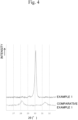
Fig. 4 ] Diagram showing results of measurements of oxides of Example 1 and Comparative Example 1 by XRD. - [
Fig. 5 ] Schematic diagram of an inductor in which the dust core is used. - [
Fig. 6 ] Schematic diagram of an inductor in which the dust core is used. - [
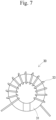
Fig. 7 ] Schematic diagram of an inductor in which the dust core is used. - [
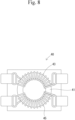
Fig. 8 ] Schematic diagram of a noise filter in which the dust core is used. - [
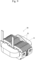
Fig. 9 ] Schematic diagram of a reactor in which the dust core is used. - [
Fig. 10 ] Schematic diagram of a transformer in which the dust core is used. - [
Fig. 11 ] Circuit diagram of a noise filter in which the dust core is used. - [
Fig. 12 ] Schematic diagram of a motor in which the dust core is used. - [
Fig. 13 ] Schematic diagram of a generator in which the dust core is used. - Here, desirable examples of the present disclosure are shown.
- [2] The insulation-coated soft magnetic metal powder according to [1], wherein the oxide is stabilized zirconia or partially stabilized zirconia.
- [3] A dust core including the insulation-coated soft magnetic metal powder according to [1] or [2].
- [4] An electronic element including the dust core according to [3].
- [5] The electronic element according to [4], including the dust core and a coil.
- [6] An electronic device including the electronic element according to [4].
- [7] An electric motor including the dust core according to [3].
- [8] A generator including the dust core according to [3].
- Hereinafter, the present disclosure will be described in detail. In the description herein, when "to" is used to describe a numerical value range, the lower limit value and the upper limit value are included unless otherwise specified. For example, when "10 to 20" is described, "10" as the lower limit value and "20" as the upper limit value are both included. That is, "10 to 20" is equivalent to "10 or more and 20 or less".
- An insulation-coated soft
magnetic metal powder 1 includes: softmagnetic metal particles 2 having an average equivalent circle diameter of 10 µm to 100 µm; and aninsulation layer 3 formed on a surface of each of the softmagnetic metal particles 2. Theinsulation layer 3 contains an oxide including Zr element. With respect to the insulation-coated softmagnetic metal powder 1, when the oxide is measured at 25°C by XRD (X-ray diffraction), the strongest peak is a cubic peak or a tetragonal peak, and the intensity of a monoclinic peak is not greater than one-tenth of the intensity of the strongest peak. - The soft
magnetic metal particles 2 are not limited in particular as long as they are metal particles being soft magnetic, and a wide range of such metal particles can be used. As the softmagnetic metal particles 2, a wide range of particles, such as those of pure iron and those of an iron-based alloy that are soft magnetic, can be used. As the iron-based alloy, an Fe-Si alloy, an Fe-Si-Cr alloy, an Fe-Si-Al alloy (sendust), an Ni-Fe alloy (permalloy), an Ni-Fe-Mo alloy (supermalloy), an Fe-based amorphous alloy, an Fe-Co alloy, or the like can be appropriately used. Among these, an Fe-Si alloy, an Fe-Si-Cr alloy, an Fe-Si-Al alloy (sendust), an Ni-Fe alloy (permalloy), and an Ni-Fe-Mo alloy (supermalloy) are preferable from the viewpoint of magnetic permeability, coercive force, and frequency characteristics. - When an Fe-Si alloy is used, an alloy having a composition composed of, for example, 0.1 mass% to 10 mass% of Si, and Fe and inevitable impurities as the remainder, can be used.
- When an Fe-Si-Cr alloy is used, an alloy having a composition composed of, for example, 0.1 mass% to 10 mass% of Si, 10 mass% to 20 mass% of Cr, and Fe and inevitable impurities as the remainder, can be used.
- The average equivalent circle diameter of the soft
magnetic metal particles 2 is 10 µm or more and 100 µm or less, preferably 25 µm or more and 100 µm or less, and more preferably 50 µm or more and 100 m or less. The average equivalent circle diameter of the softmagnetic metal particles 2 can be changed as appropriate depending on the frequency band that is used. In particular, when it is assumed to be used in a high frequency band exceeding 100 kHz, the average equivalent circle diameter is more preferably 10 µm or more and 25 µm or less. - The average equivalent circle diameter of the soft
magnetic metal particles 2 can be obtained by calculating an area-equivalent circle diameter from each particle area obtained through observation of a cross section by an FE-SEM. For example, in a case of adust core 10, thedust core 10 including the insulation-coated softmagnetic metal powder 1 is molded, and a cross section of thedust core 10 is observed to obtain the average equivalent circle diameter (seeFig. 1 ). Specifically, an area-equivalent circle diameter is calculated from each particle area obtained through observation of a cross section of thedust core 10 by an FE-SEM, and the area-equivalent circle diameter is used for the average equivalent circle diameter. More specifically, the average equivalent circle diameter is obtained as follows. In a predetermined observation field of view (e.g., 200 µm × 200 µm), multiple softmagnetic metal particles 2 that can be observed without missing parts are focused on. The diameter of an ideal circle (perfect circle) having an area equal to the area (projected area) of each particle image of the soft magnetic metal particles 2 (area-equivalent circle diameter) is calculated as an equivalent circle diameter of each particle. Then, the respective equivalent circle diameters of the particles are arithmetically averaged, whereby the average equivalent circle diameter is obtained. The equivalent circle diameter of each particle and the average equivalent circle diameter can be obtained by using general image analysis software. - The
insulation layer 3 contains an oxide including Zr (zirconium) element. When theinsulation layer 3 is observed by a TEM (transmission electron microscope), particles forming theinsulation layer 3 are confirmed. At least a part of the particles is formed by a crystal of the above oxide. - The average equivalent circle diameter of the particles forming the
insulation layer 3 is not limited in particular. From the viewpoint of reducing eddy current loss, the average equivalent circle diameter of the particles forming theinsulation layer 3 is preferably 20 nm or more and 50 nm or less. The average equivalent circle diameter of the particles forming theinsulation layer 3 can be controlled by adjusting the particle diameter of the raw material of theinsulation layer 3. - The average equivalent circle diameter of the particles forming the
insulation layer 3 can be obtained by calculating an area-equivalent circle diameter from each particle area obtained through observation of a cross section by a TEM. For example, in a case of thedust core 10, thedust core 10 including the insulation-coated softmagnetic metal powder 1 is molded, and a cross section of thedust core 10 is observed to obtain the average equivalent circle diameter. Specifically, an area-equivalent circle diameter is calculated from each particle area obtained through observation of a cross section of thedust core 10 by a TEM, and the area-equivalent circle diameter is used for the average equivalent circle diameter. More specifically, the average equivalent circle diameter is obtained as follows. In observation fields of view of five squares each being 300 nm × 300 nm, multiple particles that can be observed without missing parts are focused on. The diameter of an ideal circle (perfect circle) having an area equal to the area (projected area) of each particle image (area-equivalent circle diameter) is calculated as an equivalent circle diameter of each particle. Then, the respective equivalent circle diameters of the particles are arithmetically averaged, whereby the average equivalent circle diameter is obtained. The equivalent circle diameter of each particle and the average equivalent circle diameter can be obtained by using general image analysis software. - The above oxide is preferably stabilized zirconia or partially stabilized zirconia from the viewpoint of appropriate loss reduction of the insulation-coated soft
magnetic metal powder 1. Stabilized zirconia is zirconia obtained by solid-solving a stabilizer in ZrO2 (zirconia) such that cubic crystals are stably present at room temperature (25°C). Stabilized zirconia can have a cubic fluorite structure. Partially stabilized zirconia is zirconia obtained by solid-solving a stabilizer by a smaller amount than that for stabilized zirconia in ZrO2, and in general, cubic crystals and tetragonal crystals are present in a dispersed manner at room temperature. - Examples of the stabilizer include at least one type of an oxide of Y (yttrium), Ca (calcium), Mg (magnesium), and other rare earth elements. Examples of the other rare earth elements include La (lanthanum), Ce (cerium), Nd (neodymium), Sm (samarium), Gd (gadolinium), Dy (dysprosium), Er (erbium), and Yb (ytterbium).
- The above oxide is preferably stabilized zirconia or partially stabilized zirconia that contains yttria (Y2O3). When producing stabilized zirconia or partially stabilized zirconia, Ca is heated to 1100°C or higher and then reacted with ZrO2, or Mg is heated to 1300°C or higher and then reacted with ZrO2. Meanwhile, Y reacts with ZrO2 even at 1000°C or lower, and thus, stabilized zirconia or partially stabilized zirconia that contains yttria can be easily and inexpensively produced. In addition, Y is inexpensive as compared with the other rare earth elements and is advantageous in terms of cost.
-
Fig. 2 is an equilibrium diagram of Y2O3-ZrO2 cited from "Fig.Zr-150" of "AcerS - NIST Phase Equilibria Diagrams", which is a database of equilibrium diagrams. InFig. 2 , "Tet ss I" represents a lower temperature tetragonal polymorph, "Tet ss II" represents a higher temperature tetragonal polymorph, and "Mon ss" represents a monoclinic polymorph. - From the viewpoint of inhibiting generation of monoclinic ZrO2, the amount of yttria in stabilized zirconia or partially stabilized zirconia is preferably 2 mol% or more, and more preferably 7 mol% or more. From the viewpoint of inhibiting generation of a Zr3Y4O12 phase, the amount of yttria in stabilized zirconia or partially stabilized zirconia is preferably 20 mol% or more. From these viewpoints, the amount of yttria in stabilized zirconia or partially stabilized zirconia is preferably 2 mol% or more and 20 mol% or less, and more preferably 7 mol% or more and 20 mol% or less. The amount of yttria in stabilized zirconia or partially stabilized zirconia may be 15 mol% or less, may be 12 mol% or less, or may be 10 mol% or less.
- The above oxide may be stabilized zirconia or partially stabilized zirconia that contains calcia (CaO).
-
Fig. 3 is an equilibrium diagram of CaO-ZrO2 cited from "Fig.Zr-058" of "AcerS - NIST Phase Equilibria Diagrams", which is a database of equilibrium diagrams. InFig. 3 , "Cub" represents cubic, "Mon" represents monoclinic, and "Tet" represents tetragonal. - From the viewpoint of inhibiting generation of monoclinic ZrO2, the amount of calcia in stabilized zirconia or partially stabilized zirconia is preferably 3 mol% or more, more preferably 7 mol% or more, and further preferably 10 mol% or more. From the viewpoint of inhibiting generation of a CaZr4O9 phase or a CaZrO3 phase, the amount of calcia in stabilized zirconia or partially stabilized zirconia is preferably 20 mol% or less. From these viewpoints, the amount of calcia in stabilized zirconia or partially stabilized zirconia is preferably 3 mol% or more and 20 mol% or less, and more preferably 7 mol% or more and 20 mol% or less.
- The above oxide may be stabilized zirconia or partially stabilized zirconia that contains magnesia (MgO).
- From the viewpoint of inhibiting generation of monoclinic ZrO2, the amount of magnesia in stabilized zirconia or partially stabilized zirconia is preferably 4 mol% or more, more preferably 7 mol% or more, and further preferably 10 mol% or more. From the viewpoint of inhibiting generation of an MgO phase, the amount of magnesia in stabilized zirconia or partially stabilized zirconia is preferably 20 mol% or less. From these viewpoints, the amount of magnesia in stabilized zirconia or partially stabilized zirconia is preferably 4 mol% or more and 20 mol% or less, and more preferably 7 mol% or more and 20 mol% or less.
- With respect to the insulation-coated soft
magnetic metal powder 1, when the oxide is measured at 25°C by XRD, the strongest peak is a cubic peak or a tetragonal peak, and the intensity of a monoclinic peak is not greater than one-tenth of the intensity of the strongest peak. When multiple monoclinic peaks are observed, the peak having the highest intensity out of the multiple monoclinic peaks is specified as the monoclinic peak. When the strongest peak is a cubic peak or a tetragonal peak, and no monoclinic peak is observed, the intensity of the monoclinic peak is 0, and thus, is not greater than one-tenth of the intensity of the strongest peak. - A fact that the strongest peak is a cubic peak or a tetragonal peak, and the intensity of a monoclinic peak is not greater than one-tenth of the intensity of the strongest peak serves as one index indicating that, in the oxide, the amount of monoclinic ZrO2 is small and a large amount of ZrO2 is present as being cubic or tetragonal. In XRD, the peak of tetragonal ZrO2 and the peak of cubic ZrO2 overlap each other and are difficult to be separated from each other, and thus, a fact that the strongest peak is a cubic peak or tetragonal peak is set as one of the present requirements. From the viewpoint of reducing eddy current loss, ZrO2 is preferably present as cubic ZrO2. That is, it is preferable that, when the oxide is measured at 25°C by XRD, a peak of cubic ZrO2 is detected.
- The crystal phase showing the strongest peak of the oxide including Zr element can be controlled, for example, through addition of a stabilizer and the concentration of the stabilizer, adjustment of the particle diameter of the raw material of the
insulation layer 3, adjustment of a heat treatment condition and the like in a production method described later, and the like. - The strongest peak of the oxide including Zr element can be obtained through XRD measurement of the
dust core 10 including the insulation-coated softmagnetic metal powder 1. The XRD measurement is performed under the following conditions, for example. - · Apparatus: Rigaku SmartLab
- · X-ray: CuKα1
- · Tube voltage: 40 kV
- · Tube current: 30 mA
- · Scan speed: 5°/min
- · Sampling width: 0.02°
- · Measurement range (2θ): 10° to 80°
- · Entrance slit: 1/2°
- · Light-receiving slit 1: 15.000 mm
- · Light-receiving slit 2: 20.000 mm
- In the diffraction pattern of the
dust core 10 obtained in the XRD measurement, peaks derived from the softmagnetic metal particles 2, a measurement cell, etc., are excluded, and a peak derived from the oxide including Zr element is obtained. When the number of peaks derived from the oxide including Zr element is one, the peak is specified as the strongest peak. When there are multiple peaks derived from the oxide including Zr element, the peak having the highest intensity out of the multiple peaks is specified as the strongest peak. - More specific description will be given below with reference to
Fig. 4 . The upper one inFig. 4 is a diffraction pattern of an oxide of Example 1 described later. The strongest peak of the oxide of Example 1 is a peak of tetragonal ZrO2 (1,0,1) or cubic ZrO2 (1,1,1) that appears near 2θ≈30.1°. The lower one inFig. 4 is a diffraction pattern of an oxide of Comparative Example 1 described later. The strongest peak of the oxide of Comparative Example 1 is a peak of monoclinic ZrO2 (-1,1,1) that appears near 2θ≈28.2°. In Comparative Example 1, near 2θ≈31.4°, a peak of monoclinic ZrO2 (1,1,1) is observed. Details of each peak are as follows. - · Monoclinic ZrO2
- (hkl) of strongest peak: (-1,1,1)
- d value of strongest peak: 3.140 to 3.220
- 2θ of strongest peak (λ=1.54059): 27.68° to 28.40°
- · Tetragonal ZrO2
- (hkl) of strongest peak: (1,0,1)
- d value of strongest peak: 2.930 to 3.000
- 2θ of strongest peak (λ=1.54059): 29.76° to 30.48°
- · Cubic ZrO2
- (hkl) of strongest peak: (1,1,1)
- d value of strongest peak: 2.920 to 3.000
- 2θ of strongest peak (λ=1.54059): 29.76° to 30.59°
- In the present embodiment, the reason why loss can be reduced in the insulation-coated soft magnetic metal powder 1 (the dust core 10) is not certain, but can be inferred as follows.
- Usually, pure ZrO2 is present as being monoclinic at normal temperature. Monoclinic ZrO2 undergoes phase transformation from monoclinic to tetragonal during increase in temperature, and at this time, undergoes 4% volume shrinkage. Conversely, during decrease in temperature, Monoclinic ZrO2 undergoes volume expansion. In a case where a predetermined amount or more of monoclinic ZrO2 is included as the oxide, shrinkage and expansion are caused when annealing, etc., are performed for the purpose of removing strain of metal (reducing hysteresis loss), and there is a concern that eddy current loss due to breakage of the
insulation layer 3 caused by the shrinkage and the expansion may increase. The temperature at which this phase transformation occurs is 1170°C according to an equilibrium diagram. When ZrO2 is nanoparticles, the temperature at which the phase transformation occurs is lowered, and the phase transformation may occur even at 750°C. - In the present embodiment, cubic ZrO2 in a high temperature phase is stabilized even at room temperature through, for example, addition of a stabilizer (e.g., yttrium), so that annealing can be performed at a high temperature without causing the phase transformation of ZrO2. As a result, it is inferred that, while increase in eddy current loss due to breakage of the
insulation layer 3 is suppressed, hysteresis loss can be sufficiently reduced by annealing, and loss reduction of the insulation-coated soft magnetic metal powder 1 (the dust core 10) can be achieved. - The above insulation-coated soft
magnetic metal powder 1 is useful as a material of a dust core. That is, thedust core 10 preferably includes the insulation-coated softmagnetic metal powder 1. In the description of thedust core 10, regarding similar points, the description of the insulation-coated softmagnetic metal powder 1 above will be referred to. - The production method for the insulation-coated soft
magnetic metal powder 1 and thedust core 10 is not limited in particular. An example is described below. - A suspension including zirconia particles, yttrium acetate, and a small amount of an organic component is mixed with a soft magnetic metal powder, and the mixture is dried. The soft magnetic metal powder is not limited in particular as long as it is metal particles being soft magnetic, and a wide range of such metal particles can be used. The source of yttrium may be an oxide of yttrium or a nitrate other than yttrium acetate. The obtained dry powder is subjected to heat treatment to obtain the insulation-coated soft
magnetic metal powder 1. The condition for this heat treatment is not limited in particular. As the heat treatment condition, for example, conditions of heat treatment temperature of 750°C to 1200°C and an inert atmosphere (N2 atmosphere, Ar atmosphere) are appropriately adopted. - The insulation-coated soft
magnetic metal powder 1 is put in a mold and subjected to press molding at a molding pressure of 1.0 GPa to 1.7 GPa, to obtain a molded body. - The obtained molded body is subjected to heat treatment (annealing) to obtain the
dust core 10. As the heat treatment condition, for example, conditions of: heat treatment temperature of 600°C to 1200°C; a temperature increase rate at 350°C to 600°C of 3°C/min or more; a holding time of 10 minutes to 120 minutes; and an inert atmosphere (N2 atmosphere, Ar atmosphere) are appropriately adopted. - The heat treatment condition is changed as appropriate according to the types of the soft magnetic metal powder and the oxide that are used.
- The
dust core 10 above is suitably used in an electronic element. Examples of the electronic element include an inductor, a choking coil, a noise filter, a reactor, and a transformer. The electronic element includes thedust core 10 and a coil, for example. -
Inductors Fig. 5 to Fig. 7 are examples of the electronic element of the present disclosure. Theinductor 100 shown inFig. 5 includes adust core 11 and acoil 13. Theinductor 20 shown inFig. 6 includes adust core 21 and acoil 23. Theinductor 30 shown inFig. 7 includes adust core 31 and acoil 33. Thedust cores dust core 10. - A
noise filter 40 shown inFig. 8 is an example of the electronic element of the present disclosure. Thenoise filter 40 includes adust core 41 and a pair ofcoils dust core 41 has a configuration similar to that of thedust core 10. - A
reactor 50 shown inFig. 9 is an example of the electronic element of the present disclosure. Thereactor 50 includes adust core 51 and acoil 53. Thedust core 51 has a configuration similar to that of thedust core 10. - A
transformer 60 shown inFig. 10 is an example of the electronic element of the present disclosure. Thetransformer 60 includes adust core 61 and a pair ofcoils dust core 61 has a configuration similar to that of thedust core 10 above. - The
dust core 10 above is suitably used in an electronic device. The electronic device includes an electronic element. Examples of the electronic element include the electronic elements described above. - A
noise filter 70 shown inFig. 11 is an example of the electronic device of the present disclosure. Thenoise filter 70 includes anelement 71 andcapacitors element 71 corresponds to an example of an "electronic element" of the present disclosure. Theelement 71 is an element having a configuration similar to that of thenoise filter 40 shown inFig. 8 , for example. - The
dust core 10 above is suitably used in an electric motor. Examples of the electric motor include a motor, a linear actuator, and the like. - A
motor 80 shown inFig. 12 is an example of an electric motor of the present disclosure. Themotor 80 includes arotor 80A and astator 80B. Thestator 80B has adust core 81 and acoil 83. Thedust core 81 has a configuration similar to that of thedust core 10 above. - A
generator 90 shown inFig. 13 is an example of a generator of the present disclosure. Thegenerator 90 includes arotor 90A and astator 90B. Thestator 90B has adust core 91 and acoil 93. Thedust core 91 has a configuration similar to that of thedust core 10 above. - Hereinafter, the present disclosure will be further specifically described with reference to Examples.
- A suspension including zirconia particles, yttrium acetate, a small amount of an organic component, and a solvent was mixed with pure iron particles, and the mixture was dried and subjected to heat treatment. The concentration of oxide particles in the suspension was set to 0.1 mass% to 2 mass% with respect to the entire suspension. The amount of the suspension that was mixed with soft magnetic metal particles was set such that the entire amount of the contained oxide particles was 6 volume% with respect to the soft magnetic metal particles. The amount of yttrium acetate was set such that Zr element was 84 mol% and Y element was 16 mol% (8 mol% in terms of Y2O3). The conditions of the heat treatment (first heat treatment) were a heat treatment temperature of 900°C and in nitrogen. The heat treatment was performed for the purpose of removing the organic component in the insulation layer and advancing solid solution reaction of the oxide. In this manner, an insulation-coated soft magnetic metal powder of Example 1 was obtained.
- The obtained insulation-coated soft magnetic metal powder was put in a mold and subjected to press molding at a molding pressure of 1.7 GPa, whereby a press molded body having a diameter of 10 mm or a toroidal shape (outer diameter: 8 mm, inner diameter: 4.5 mm, height: 1.5 mm) was obtained. This molded body was subjected to heat treatment (second heat treatment). The conditions of the heat treatment were a heat treatment temperature of 600°C to 1200°C, a temperature increase rate in a range of 350°C to 600°C of 3°C/min to 10°C/min, and in nitrogen. In this manner, a dust core of Example 1 was obtained.
- A dust core of Example 2 was obtained in the same manner as that in Example 1 except that Fe-3.5 mass% Si alloy particles were used instead of the pure iron particles.
- A dust core of Comparative Example 1 was obtained in the same manner as that in Example 1 except that yttrium acetate was not added.
- A dust core of Comparative Example 2 was obtained in the same manner as that in Example 2 except that yttrium acetate was not added.
- Table 1 collectively shows characteristics of the soft magnetic metal particles, the insulation layer, and the eddy current loss of Examples and Comparative Examples.
- The column of "Crystal phase of strongest peak" indicates the crystal phase of the strongest peak specified by the method described in the embodiment.
- In the column of "Intensity of monoclinic peak relative to intensity of strongest peak", evaluation was performed, with respect to the intensity of the strongest peak and the intensity of the monoclinic peak specified by the method described in the embodiment, according to the criteria below. When the crystal phase of the intensity of the strongest peak is monoclinic, the intensity of the monoclinic peak and the intensity of the strongest peak are the same, and thus, the intensity of the monoclinic peak relative to the intensity of the strongest peak is 1.
- Not greater than 1/10: the intensity of the monoclinic peak is not greater than one-tenth of the intensity of the strongest peak.
- Greater than 1/10: the intensity of the monoclinic peak is greater than one-tenth of the intensity of the strongest peak.
- In the column of "Satisfaction of requirement about intensity of monoclinic peak", evaluation was performed according to the criteria below.
- Satisfied: "Crystal phase of strongest peak" is cubic or tetragonal, and "Intensity of monoclinic peak relative to intensity of strongest peak" is not greater than 1/10.
- Not satisfied: "Crystal phase of strongest peak" is not cubic or tetragonal, or "Intensity of monoclinic peak relative to intensity of strongest peak" is greater than 1/10.
[Table 1] Soft magnetic metal particle Insulation layer Eddy current loss (kW/m3) Composition Crystal phase of strongest peak Intensity of monoclinic peak relative to intensity of strongest peak Satisfaction of requirement about intensity of monoclinic peak Example 1 Fe Cubic or tetragonal Not greater than 1/10 Satisfied 14.4 Example 2 Fe-3.5% Si Cubic or tetragonal Not greater than 1/10 Satisfied 5.3 Comparative Example 1 Fe Monoclinic Greater than 1/10 Not satisfied 537.4 Comparative Example 2 Fe-3.5% Si Monoclinic Greater than 1/10 Not satisfied 109.0 - Eddy current loss (kW/m3) of the obtained dust core was measured under conditions of a frequency of 10 kHz and a magnetic flux density of 0.1 T. The measurement results are also shown in Table 1.
- Examples 1, 2 satisfy requirements (a), (b), (c), (d) below.
- · Requirement (a): soft magnetic metal particles having an average equivalent circle diameter of 10 µm to 100 µm are included.
- · Requirement (b): an insulation layer formed on a surface of each of the soft magnetic metal particles is included.
- · Requirement (c): the insulation layer contains an oxide including Zr element.
- · Requirement (d): when the oxide is measured at 25°C by XRD, the strongest peak is a cubic peak or a tetragonal peak, and the intensity of a monoclinic peak is not greater than one-tenth of the intensity of the strongest peak.
- In contrast to this, Comparative Examples 1, 2 do not satisfy requirement (d).
- Examples 1, 2 had low eddy current losses as compared with those of Comparative Examples 1, 2.
- Example 1, in which the composition of the soft magnetic metal particles was pure iron, had a low eddy current loss as compared with that of Comparative Example 1 having the same composition. Example 2, in which the composition of the soft magnetic metal particles was an Fe-3.5 mass% Si alloy, had a low eddy current loss as compared with that of Comparative Example 2 having the same composition. From these results, it was suggested that the composition of the soft magnetic metal particles is not limited in particular and that a wide range of the soft magnetic metal particles is applicable.
- According to the present embodiment, loss reduction of the insulation-coated soft magnetic metal powder can be achieved.
- The present disclosure is not limited to the embodiment described above in detail, and various modifications or variations can be made without departing from the scope of the claims.
- The dust core of the present disclosure is particularly suitably used for usages as a motor, a transformer, a reactor, an inductor, a noise filter, and the like.
-
- 1: insulation-coated soft magnetic metal powder
- 2: soft magnetic metal particle
- 3: insulation layer
- 10: dust core
- 11, 21, 31, 41, 51, 61, 81, 91: dust core
- 100, 20, 30: inductor (electronic element)
- 13, 23, 33, 43, 45, 53, 63, 65, 83, 93: coil
- 40: noise filter (electronic element)
- 50: reactor (electronic element)
- 60: transformer (electronic element)
- 70: noise filter (electronic device)
- 80: motor (electric motor)
- 90: generator
Claims (8)
- An insulation-coated soft magnetic metal powder comprising:soft magnetic metal particles having an average equivalent circle diameter of 10 µm to 100 µm; andan insulation layer formed on a surface of each of the soft magnetic metal particles, whereinthe insulation layer contains an oxide including Zr element, andwhen the oxide is measured at 25°C by XRD,a strongest peak is a cubic peak or a tetragonal peak, andan intensity of a monoclinic peak is not greater than one-tenth of an intensity of the strongest peak.
- The insulation-coated soft magnetic metal powder according to claim 1, wherein the oxide is stabilized zirconia or partially stabilized zirconia.
- A dust core including the insulation-coated soft magnetic metal powder according to claim 1 or 2.
- An electronic element comprising the dust core according to claim 3.
- The electronic element according to claim 4, comprising the dust core and a coil.
- An electronic device comprising the electronic element according to claim 4.
- An electric motor comprising the dust core according to claim 3.
- A generator comprising the dust core according to claim 3.
Applications Claiming Priority (2)
| Application Number | Priority Date | Filing Date | Title |
|---|---|---|---|
| JP2022081309 | 2022-05-18 | ||
| PCT/JP2023/017052 WO2023223826A1 (en) | 2022-05-18 | 2023-05-01 | Insulated covered soft magnetic metal powder, magnetic dust core, electronic element, electronic device, electric motor and power generator |
Publications (2)
| Publication Number | Publication Date |
|---|---|
| EP4528757A1 true EP4528757A1 (en) | 2025-03-26 |
| EP4528757A4 EP4528757A4 (en) | 2026-04-22 |
Family
ID=88835102
Family Applications (1)
| Application Number | Title | Priority Date | Filing Date |
|---|---|---|---|
| EP23807433.0A Pending EP4528757A4 (en) | 2022-05-18 | 2023-05-01 | Insulated coated soft magnetic metal powder, magnetic powder core, electronic element, electronic device, electric motor and generator |
Country Status (6)
| Country | Link |
|---|---|
| US (1) | US20250010365A1 (en) |
| EP (1) | EP4528757A4 (en) |
| JP (1) | JP7499421B2 (en) |
| KR (1) | KR102836853B1 (en) |
| CN (1) | CN118339624A (en) |
| WO (1) | WO2023223826A1 (en) |
Family Cites Families (12)
| Publication number | Priority date | Publication date | Assignee | Title |
|---|---|---|---|---|
| EP0406580B1 (en) * | 1989-06-09 | 1996-09-04 | Matsushita Electric Industrial Co., Ltd. | A composite material and a method for producing the same |
| JPH10335128A (en) | 1997-03-31 | 1998-12-18 | Tdk Corp | Ferromagnetic powder for dust core, dust core and method of manufacturing the same |
| JP2000049008A (en) * | 1998-07-29 | 2000-02-18 | Tdk Corp | Ferromagnetic powder for dust core dust core, and its manufacture |
| JP4560784B2 (en) * | 2004-02-24 | 2010-10-13 | 日立金属株式会社 | Fine metal particles, method for producing the same, and magnetic beads |
| JP5556756B2 (en) * | 2004-02-27 | 2014-07-23 | 日立金属株式会社 | Iron-based nano-sized particles and method for producing the same |
| JP4613622B2 (en) * | 2005-01-20 | 2011-01-19 | 住友電気工業株式会社 | Soft magnetic material and dust core |
| JP6113516B2 (en) * | 2012-02-06 | 2017-04-12 | Ntn株式会社 | Magnetic core powder and powder magnetic core |
| WO2018052107A1 (en) * | 2016-09-15 | 2018-03-22 | 日立金属株式会社 | Magnetic core and coil component |
| JP7069949B2 (en) * | 2018-03-28 | 2022-05-18 | Tdk株式会社 | Composite magnetic material |
| JP2019192868A (en) | 2018-04-27 | 2019-10-31 | セイコーエプソン株式会社 | Insulator coating soft magnetic powder, dust core, magnetic element, electronic apparatus, and moving body |
| JP2021052075A (en) * | 2019-09-25 | 2021-04-01 | 太陽誘電株式会社 | Coil component |
| CN113674984B (en) * | 2021-08-26 | 2023-03-21 | 合肥工业大学 | Preparation method of FeSiAlZrScSr magnetic powder core |
-
2023
- 2023-05-01 KR KR1020247021835A patent/KR102836853B1/en active Active
- 2023-05-01 WO PCT/JP2023/017052 patent/WO2023223826A1/en not_active Ceased
- 2023-05-01 CN CN202380014771.3A patent/CN118339624A/en active Pending
- 2023-05-01 EP EP23807433.0A patent/EP4528757A4/en active Pending
- 2023-05-01 JP JP2023544516A patent/JP7499421B2/en active Active
- 2023-05-01 US US18/705,207 patent/US20250010365A1/en active Pending
Also Published As
| Publication number | Publication date |
|---|---|
| KR20240113944A (en) | 2024-07-23 |
| JP7499421B2 (en) | 2024-06-13 |
| WO2023223826A1 (en) | 2023-11-23 |
| EP4528757A4 (en) | 2026-04-22 |
| KR102836853B1 (en) | 2025-07-21 |
| US20250010365A1 (en) | 2025-01-09 |
| JPWO2023223826A1 (en) | 2023-11-23 |
| CN118339624A (en) | 2024-07-12 |
Similar Documents
| Publication | Publication Date | Title |
|---|---|---|
| EP0872856B1 (en) | Magnetic core and method of manufacturing the same | |
| KR100531253B1 (en) | Method for Making Nano Scale Grain Metal Powders Having Excellent High Frequency Characteristics and Method for Making Soft Magnetic Core for High Frequency Using the Same | |
| US8083867B2 (en) | Amorphous alloy ribbon, nanocrystalline soft magnetic alloy and magnetic core consisting of nanocrystalline soft magnetic alloy | |
| US20180108465A1 (en) | Magnetic powder and production method thereof, magnetic core and production method thereof, and coil component | |
| US7141127B2 (en) | Low core loss magnetic alloy with high saturation magnetic flux density and magnetic parts made of same | |
| EP2578338B1 (en) | Soft magnetic powder, powder granules, dust core, electromagnetic component, and method for producing dust core | |
| US10748688B2 (en) | Soft magnetic alloy and magnetic device | |
| JP3624681B2 (en) | Composite magnetic material and method for producing the same | |
| EP3441989A1 (en) | Dust core coated with silica-based insulation, method for manufacturing same, and electromagnetic circuit component | |
| CN103180917A (en) | Rare earth-iron-nitrogen system alloy material, method for producing rare earth-iron-nitrogen system alloy material, rare earth-iron system alloy material, and method for producing rare earth-iron system alloy material | |
| US20180122542A1 (en) | Soft magnetic alloy and magnetic device | |
| JP2007019134A (en) | Method for producing composite magnetic material | |
| EP1702903B1 (en) | Ferrite sintered compact and method for producing the same, and electronic parts using the same | |
| EP2330602B1 (en) | Composite magnetic material and process for producing the composite magnetic material | |
| JP5472694B2 (en) | Composite sintered body of aluminum oxide and iron, and method for producing the same | |
| US20250010365A1 (en) | Insulation-coated soft magnetic metal powder, dust core, electronic element, electronic device, electric motor, and generator | |
| KR100383394B1 (en) | Method for Producing Manganese-Zinc Ferrite Core, and Manganses-Zinc Ferrite Core | |
| US20200075203A1 (en) | Magnet material, permanent magnet, rotary electric machine, and vehicle | |
| EP4641593A1 (en) | Alloy particles, powder magnetic core, electronic element, electronic appliance, electric motor, and dynamo | |
| JP2011208184A (en) | Magnetic composite powder, and method for producing the same | |
| US20150017056A1 (en) | Soft magnetic metal powder, method for preparing the same, and electronic components including the same as core material | |
| KR102927257B1 (en) | Pressure cores, alloy particles, electronic components, electronic devices, motors and generators | |
| CN118197728A (en) | R-T-B permanent magnet material, and preparation method and application thereof | |
| WANG et al. | 1 Introduction▲ 2 Experimental▲ | |
| JP2000049009A (en) | Dust core and manufacturing method thereof |
Legal Events
| Date | Code | Title | Description |
|---|---|---|---|
| STAA | Information on the status of an ep patent application or granted ep patent |
Free format text: STATUS: THE INTERNATIONAL PUBLICATION HAS BEEN MADE |
|
| PUAI | Public reference made under article 153(3) epc to a published international application that has entered the european phase |
Free format text: ORIGINAL CODE: 0009012 |
|
| STAA | Information on the status of an ep patent application or granted ep patent |
Free format text: STATUS: REQUEST FOR EXAMINATION WAS MADE |
|
| 17P | Request for examination filed |
Effective date: 20240813 |
|
| AK | Designated contracting states |
Kind code of ref document: A1 Designated state(s): AL AT BE BG CH CY CZ DE DK EE ES FI FR GB GR HR HU IE IS IT LI LT LU LV MC ME MK MT NL NO PL PT RO RS SE SI SK SM TR |
|
| DAV | Request for validation of the european patent (deleted) | ||
| DAX | Request for extension of the european patent (deleted) | ||
| A4 | Supplementary search report drawn up and despatched |
Effective date: 20260319 |
|
| RIC1 | Information provided on ipc code assigned before grant |
Ipc: H01F 1/24 20060101AFI20260313BHEP Ipc: H01F 1/33 20060101ALI20260313BHEP Ipc: H01F 27/255 20060101ALI20260313BHEP Ipc: H01F 3/08 20060101ALI20260313BHEP Ipc: B22F 1/00 20220101ALI20260313BHEP Ipc: B22F 1/16 20220101ALI20260313BHEP Ipc: B22F 3/00 20210101ALI20260313BHEP Ipc: C22C 38/00 20060101ALI20260313BHEP |