EP4528143A1 - Vessel for storing a pressurized fluid - Google Patents
Vessel for storing a pressurized fluid Download PDFInfo
- Publication number
- EP4528143A1 EP4528143A1 EP23198170.5A EP23198170A EP4528143A1 EP 4528143 A1 EP4528143 A1 EP 4528143A1 EP 23198170 A EP23198170 A EP 23198170A EP 4528143 A1 EP4528143 A1 EP 4528143A1
- Authority
- EP
- European Patent Office
- Prior art keywords
- vessel
- vessel part
- stiffener
- adhesive
- joint portion
- Prior art date
- Legal status (The legal status is an assumption and is not a legal conclusion. Google has not performed a legal analysis and makes no representation as to the accuracy of the status listed.)
- Withdrawn
Links
Images


Classifications
-
- F—MECHANICAL ENGINEERING; LIGHTING; HEATING; WEAPONS; BLASTING
- F17—STORING OR DISTRIBUTING GASES OR LIQUIDS
- F17C—VESSELS FOR CONTAINING OR STORING COMPRESSED, LIQUEFIED OR SOLIDIFIED GASES; FIXED-CAPACITY GAS-HOLDERS; FILLING VESSELS WITH, OR DISCHARGING FROM VESSELS, COMPRESSED, LIQUEFIED, OR SOLIDIFIED GASES
- F17C1/00—Pressure vessels, e.g. gas cylinder, gas tank, replaceable cartridge
- F17C1/02—Pressure vessels, e.g. gas cylinder, gas tank, replaceable cartridge involving reinforcing arrangements
- F17C1/08—Integral reinforcements, e.g. ribs
-
- F—MECHANICAL ENGINEERING; LIGHTING; HEATING; WEAPONS; BLASTING
- F17—STORING OR DISTRIBUTING GASES OR LIQUIDS
- F17C—VESSELS FOR CONTAINING OR STORING COMPRESSED, LIQUEFIED OR SOLIDIFIED GASES; FIXED-CAPACITY GAS-HOLDERS; FILLING VESSELS WITH, OR DISCHARGING FROM VESSELS, COMPRESSED, LIQUEFIED, OR SOLIDIFIED GASES
- F17C2201/00—Vessel construction, in particular geometry, arrangement or size
- F17C2201/01—Shape
- F17C2201/0104—Shape cylindrical
- F17C2201/0109—Shape cylindrical with exteriorly curved end-piece
-
- F—MECHANICAL ENGINEERING; LIGHTING; HEATING; WEAPONS; BLASTING
- F17—STORING OR DISTRIBUTING GASES OR LIQUIDS
- F17C—VESSELS FOR CONTAINING OR STORING COMPRESSED, LIQUEFIED OR SOLIDIFIED GASES; FIXED-CAPACITY GAS-HOLDERS; FILLING VESSELS WITH, OR DISCHARGING FROM VESSELS, COMPRESSED, LIQUEFIED, OR SOLIDIFIED GASES
- F17C2201/00—Vessel construction, in particular geometry, arrangement or size
- F17C2201/03—Orientation
- F17C2201/035—Orientation with substantially horizontal main axis
-
- F—MECHANICAL ENGINEERING; LIGHTING; HEATING; WEAPONS; BLASTING
- F17—STORING OR DISTRIBUTING GASES OR LIQUIDS
- F17C—VESSELS FOR CONTAINING OR STORING COMPRESSED, LIQUEFIED OR SOLIDIFIED GASES; FIXED-CAPACITY GAS-HOLDERS; FILLING VESSELS WITH, OR DISCHARGING FROM VESSELS, COMPRESSED, LIQUEFIED, OR SOLIDIFIED GASES
- F17C2201/00—Vessel construction, in particular geometry, arrangement or size
- F17C2201/05—Size
- F17C2201/054—Size medium (>1 m3)
-
- F—MECHANICAL ENGINEERING; LIGHTING; HEATING; WEAPONS; BLASTING
- F17—STORING OR DISTRIBUTING GASES OR LIQUIDS
- F17C—VESSELS FOR CONTAINING OR STORING COMPRESSED, LIQUEFIED OR SOLIDIFIED GASES; FIXED-CAPACITY GAS-HOLDERS; FILLING VESSELS WITH, OR DISCHARGING FROM VESSELS, COMPRESSED, LIQUEFIED, OR SOLIDIFIED GASES
- F17C2203/00—Vessel construction, in particular walls or details thereof
- F17C2203/01—Reinforcing or suspension means
- F17C2203/011—Reinforcing means
- F17C2203/012—Reinforcing means on or in the wall, e.g. ribs
-
- F—MECHANICAL ENGINEERING; LIGHTING; HEATING; WEAPONS; BLASTING
- F17—STORING OR DISTRIBUTING GASES OR LIQUIDS
- F17C—VESSELS FOR CONTAINING OR STORING COMPRESSED, LIQUEFIED OR SOLIDIFIED GASES; FIXED-CAPACITY GAS-HOLDERS; FILLING VESSELS WITH, OR DISCHARGING FROM VESSELS, COMPRESSED, LIQUEFIED, OR SOLIDIFIED GASES
- F17C2203/00—Vessel construction, in particular walls or details thereof
- F17C2203/06—Materials for walls or layers thereof; Properties or structures of walls or their materials
- F17C2203/0634—Materials for walls or layers thereof
- F17C2203/0658—Synthetics
- F17C2203/0663—Synthetics in form of fibers or filaments
-
- F—MECHANICAL ENGINEERING; LIGHTING; HEATING; WEAPONS; BLASTING
- F17—STORING OR DISTRIBUTING GASES OR LIQUIDS
- F17C—VESSELS FOR CONTAINING OR STORING COMPRESSED, LIQUEFIED OR SOLIDIFIED GASES; FIXED-CAPACITY GAS-HOLDERS; FILLING VESSELS WITH, OR DISCHARGING FROM VESSELS, COMPRESSED, LIQUEFIED, OR SOLIDIFIED GASES
- F17C2209/00—Vessel construction, in particular methods of manufacturing
- F17C2209/22—Assembling processes
- F17C2209/227—Assembling processes by adhesive means
-
- F—MECHANICAL ENGINEERING; LIGHTING; HEATING; WEAPONS; BLASTING
- F17—STORING OR DISTRIBUTING GASES OR LIQUIDS
- F17C—VESSELS FOR CONTAINING OR STORING COMPRESSED, LIQUEFIED OR SOLIDIFIED GASES; FIXED-CAPACITY GAS-HOLDERS; FILLING VESSELS WITH, OR DISCHARGING FROM VESSELS, COMPRESSED, LIQUEFIED, OR SOLIDIFIED GASES
- F17C2209/00—Vessel construction, in particular methods of manufacturing
- F17C2209/23—Manufacturing of particular parts or at special locations
- F17C2209/232—Manufacturing of particular parts or at special locations of walls
-
- F—MECHANICAL ENGINEERING; LIGHTING; HEATING; WEAPONS; BLASTING
- F17—STORING OR DISTRIBUTING GASES OR LIQUIDS
- F17C—VESSELS FOR CONTAINING OR STORING COMPRESSED, LIQUEFIED OR SOLIDIFIED GASES; FIXED-CAPACITY GAS-HOLDERS; FILLING VESSELS WITH, OR DISCHARGING FROM VESSELS, COMPRESSED, LIQUEFIED, OR SOLIDIFIED GASES
- F17C2221/00—Handled fluid, in particular type of fluid
- F17C2221/01—Pure fluids
- F17C2221/012—Hydrogen
-
- F—MECHANICAL ENGINEERING; LIGHTING; HEATING; WEAPONS; BLASTING
- F17—STORING OR DISTRIBUTING GASES OR LIQUIDS
- F17C—VESSELS FOR CONTAINING OR STORING COMPRESSED, LIQUEFIED OR SOLIDIFIED GASES; FIXED-CAPACITY GAS-HOLDERS; FILLING VESSELS WITH, OR DISCHARGING FROM VESSELS, COMPRESSED, LIQUEFIED, OR SOLIDIFIED GASES
- F17C2221/00—Handled fluid, in particular type of fluid
- F17C2221/01—Pure fluids
- F17C2221/014—Nitrogen
-
- F—MECHANICAL ENGINEERING; LIGHTING; HEATING; WEAPONS; BLASTING
- F17—STORING OR DISTRIBUTING GASES OR LIQUIDS
- F17C—VESSELS FOR CONTAINING OR STORING COMPRESSED, LIQUEFIED OR SOLIDIFIED GASES; FIXED-CAPACITY GAS-HOLDERS; FILLING VESSELS WITH, OR DISCHARGING FROM VESSELS, COMPRESSED, LIQUEFIED, OR SOLIDIFIED GASES
- F17C2223/00—Handled fluid before transfer, i.e. state of fluid when stored in the vessel or before transfer from the vessel
- F17C2223/01—Handled fluid before transfer, i.e. state of fluid when stored in the vessel or before transfer from the vessel characterised by the phase
- F17C2223/0107—Single phase
- F17C2223/0123—Single phase gaseous, e.g. CNG, GNC
-
- F—MECHANICAL ENGINEERING; LIGHTING; HEATING; WEAPONS; BLASTING
- F17—STORING OR DISTRIBUTING GASES OR LIQUIDS
- F17C—VESSELS FOR CONTAINING OR STORING COMPRESSED, LIQUEFIED OR SOLIDIFIED GASES; FIXED-CAPACITY GAS-HOLDERS; FILLING VESSELS WITH, OR DISCHARGING FROM VESSELS, COMPRESSED, LIQUEFIED, OR SOLIDIFIED GASES
- F17C2223/00—Handled fluid before transfer, i.e. state of fluid when stored in the vessel or before transfer from the vessel
- F17C2223/01—Handled fluid before transfer, i.e. state of fluid when stored in the vessel or before transfer from the vessel characterised by the phase
- F17C2223/0146—Two-phase
- F17C2223/0153—Liquefied gas, e.g. LPG, GPL
- F17C2223/0161—Liquefied gas, e.g. LPG, GPL cryogenic, e.g. LNG, GNL, PLNG
-
- F—MECHANICAL ENGINEERING; LIGHTING; HEATING; WEAPONS; BLASTING
- F17—STORING OR DISTRIBUTING GASES OR LIQUIDS
- F17C—VESSELS FOR CONTAINING OR STORING COMPRESSED, LIQUEFIED OR SOLIDIFIED GASES; FIXED-CAPACITY GAS-HOLDERS; FILLING VESSELS WITH, OR DISCHARGING FROM VESSELS, COMPRESSED, LIQUEFIED, OR SOLIDIFIED GASES
- F17C2260/00—Purposes of gas storage and gas handling
- F17C2260/01—Improving mechanical properties or manufacturing
- F17C2260/011—Improving strength
-
- F—MECHANICAL ENGINEERING; LIGHTING; HEATING; WEAPONS; BLASTING
- F17—STORING OR DISTRIBUTING GASES OR LIQUIDS
- F17C—VESSELS FOR CONTAINING OR STORING COMPRESSED, LIQUEFIED OR SOLIDIFIED GASES; FIXED-CAPACITY GAS-HOLDERS; FILLING VESSELS WITH, OR DISCHARGING FROM VESSELS, COMPRESSED, LIQUEFIED, OR SOLIDIFIED GASES
- F17C2270/00—Applications
- F17C2270/01—Applications for fluid transport or storage
- F17C2270/0186—Applications for fluid transport or storage in the air or in space
- F17C2270/0189—Planes
Definitions
- the present invention relates to a vessel for storing a pressurized fluid. Further, the present invention relates to a method for manufacturing such vessel. In addition, the present invention relates to the use of such vessel in an aircraft or spacecraft, and an aircraft comprising such vessel.
- vessels For storing pressurized fluids, such as liquids, gases or the like, vessels may be used. Such vessel may be designed to withstand positive pressure loads, tension, etc., and/or vacuum pressure and flight loads. In at least some cases, it may be desired to install an inner system, such as, for example, pipes, sloshing walls, cables, sensing means, or the like, inside the vessel.
- an inner system such as, for example, pipes, sloshing walls, cables, sensing means, or the like
- EP 4 124 790 A1 describes a hydrogen tank for aircrafts, which tank comprises an inner vessel for storing hydrogen and an outer jacket comprising cylindrical outer jackets and outer jacket domes.
- the cylindrical outer jackets and outer jacket domes are joined together at L-shaped ends by using fasteners distributed in a staggered pattern.
- EP 4 107 420 A1 describes a composite tank for storing a cryogenic propellant.
- the tank comprises a sealing casing and a reinforcing layer.
- a vessel for storing a pressurized fluid.
- the vessel comprises a first vessel part and a second vessel part, joined together at a circumferential joint portion.
- the vessel further comprises a stiffener arranged inside the vessel to overlap the joint portion and a respective joint end of each of the first vessel part and the second vessel part, and to join the first vessel part and the second vessel part together by an adhesive.
- the stiffener is configured to join two parts of the vessel by the stiffener arranged inside the two vessel parts.
- the stiffener reinforces the joint, i.e. the joint portion, so that forces, loads, etc. can be applied onto the vessel and/or the joint without deforming the whole vessel too much.
- This also improves the bonding quality of the two vessel parts and reduces the risk of gaps, cavities, or the like in the joint and failure of the bonding.
- the vessel is composed of or may be split into multiple parts, i.e. at least the first vessel part and the second vessel part, to allow installation of one or more inner systems, such as, for example, pipes, sloshing walls, cables, sensing means, or the like, inside the vessel.
- the manufacturing of the vessel with this configuration is particularly simple because the provision and/or preparation of the vessel parts and the stiffener as well as the bonding by the adhesive are simple in terms of manufacturing technology. Also, only adhesive is needed for the bonding. Using the adhesive for the bonding of the vessel parts allows tolerances of the first and second vessel part to be at least partially compensated.
- the first vessel part may be an end part of the vessel.
- the first vessel part may have the shape of a dome or the like.
- the second vessel part may be a middle or center part of the vessel.
- the second vessel part may be cylindrical, hemispherical, spherical, or the like, wherein these shapes are only exemplary and other shapes may also withstand pressure and may thus be suitable.
- the first and second vessel parts may be brought together or close together with respective joint faces, i.e. the respective joint ends, thereby defining the joint portion.
- the stiffener is configured to reinforce the joint portion from inside the vessel.
- the stiffener is arranged and/or configured to allow application of force on the joint portion during the bonding process. For this, the stiffener extends over the joint portion, i.e. overlaps it, and further overlaps the respective joint end of the first and second vessel part.
- the adhesive is applied and/or arranged between the stiffener and the first vessel part and/or second vessel part, thereby joining the first and second vessel parts together.
- the stiffener may also be referred to as a tool, as it is used to form the bonding in joint portion. After the bonding process, the stiffener used as a tool remains in the vessel as reinforcement. If the vessel is used in an aircraft, for example, the stiffener may also be referred to as a tool that travels with the aircraft.
- the vessel may be a stand-alone tank, container or the like, or may be part of a tank, such as a double-walled tank, in which the vessel may form the inner tank.
- a tank such as a double-walled tank
- the principle underlying the proposed vessel may be applied to the outer tank of such double-walled tank.
- at least some embodiments may also refer to a double-walled tank with the vessel disclosed herein as part of the tank, for example, as the inner tank.
- the adhesive does not have to meet any special requirements, so that in principle any adhesive may be used that is configured to be bonded to the respective material of the first vessel part, second vessel part and/or stiffener.
- the provided vessel may be used to receive and/or store various fluids, such as liquids, gases, cryogenic fluids or liquids, or the like. For example, hydrogen, nitrogen, or the like may be stored, to name just a few examples.
- the vessel may be used, for example, to store low-emission fuels or the like.
- the vessel may also be used on the ground, etc. for a wide variety of applications in which a pressurized fluid is to be stored.
- the first vessel part, the second vessel part and the stiffener may form a double-shear connection.
- the joint portion may be configured to allow simultaneous shear across two, e.g. parallel, planes. In this way, the vessel can be subjected to high forces, loads, etc., or may be able to withstand them.
- the stiffener may be arranged in a surface manner on the respective first vessel part and second vessel part.
- the adhesive may be disposed between respective surfaces thereof. In this way, the vessel can be subjected to high forces, loads, etc., or may be able to withstand them. Further, manufacturing of the vessel may be simple.
- the stiffener may be formed with continuous material and/or as a closed ring.
- the vessel can be subjected to high forces, loads, etc., or may be able to withstand them. Further, manufacturing of the vessel may be simple. Diffusion of the fluid to be stored in the vessel may be reduced or avoided.
- the stiffener may be formed from a fiber composite material.
- the stiffener may be formed from a carbon fiber-reinforced polymer (CFRP), or any other fiber composite material capable of withholding pressurized fluids.
- CFRP carbon fiber-reinforced polymer
- a shape and/or cross-section of the stiffener may be selected from a flat shape, a U-cross-section, an L-cross-section, and a T-cross-section.
- the stiffener may be band shaped, for example.
- other shapes and/or cross-sections are also conceivable.
- the stiffener may be formed conically to at least one side facing the respective first vessel part and/or second vessel part. In this way, the respective first vessel part and/or second vessel part may be pushed on the stiffener and may squeeze the adhesive. For this, the respective first vessel part and/or second vessel part may be formed conically accordingly. Alternatively or additionally, in at least some embodiments, the stiffener may be angled.
- the respective joint end of at least one of the first vessel part and the second vessel part may be angled.
- the respective joint end of at least one of the first vessel part and the second vessel part may be formed conically. In this way, the angled and/or conically formed joint ends may be brought together, e.g. moved towards each other, without shifting the adhesive away. If the first vessel part and/or second vessel part have a respectively angled joint end, they may be moved over the stiffener and the contact with the adhesive is only in the final moment of the joining operation.
- At least one spacer may be arranged locally between the stiffener and the respective first and/or second vessel part.
- the spacer may be effective in lateral or radial direction.
- the at least one spacer may be applied locally.
- the at least one spacer may be configured to or may be used to provide a defined gap for the adhesive. The gap may be used to allow injection of the adhesive into the gap after joining the vessel parts, or to apply the adhesive first and then move the vessel parts towards each other without shifting the adhesive away.
- the vessel may further comprise a strip-shaped band arranged outside the vessel, e.g. an outer band, to overlap the joint portion and a respective joint end of each of the first vessel part and the second vessel part.
- the band e.g. outer band
- the band may be arranged opposite to the stiffener.
- the band may comprise the same, similar or different dimensions as the stiffener.
- the outer band may be formed from a carbon fiber-reinforced polymer (CFRP), or any other fiber composite material capable of withholding pressurized fluids.
- the outer band may be formed from a multidirectional carbon fiber-reinforced material.
- the first vessel part and/or the second vessel part may be formed from a fiber composite material.
- the first vessel part and/or second vessel part may be formed from a carbon fiber-reinforced polymer (CFRP), or any other fiber composite material capable of withholding pressurized fluids.
- CFRP carbon fiber-reinforced polymer
- the principle disclosed herein may be applied to further vessel parts.
- the vessel may comprise more than the first vessel part and second vessel part, wherein the one or more further vessel parts may be joined to the first vessel part and/or second vessel part by using a further joint portion and/or a further stiffener.
- the vessel may further comprise a third vessel part that is at least similar or identical to the first vessel part and, on a side of the second vessel part facing away from the first vessel part, is joined together with the second vessel part at a further joint portion by a further stiffener and a respective adhesive.
- a, for example, cylindrical vessel comprising domes at its ends may be provided.
- a method for manufacturing a vessel for storing a pressurized fluid may be carried out to manufacture the vessel of the first aspect and/or one or more of the above embodiments.
- the method comprises arranging a first vessel part and a second vessel part on a stiffener that the first vessel part and the second vessel part are supported, in a circumferential joint portion, by the stiffener from inside the vessel.
- the stiffener overlaps the joint portion and a respective joint end of each of the first vessel part and the second vessel part.
- the method further comprises providing an adhesive to join the first vessel part and the second vessel part together.
- the stiffener first serves as a tool for facilitating the joining and/or bonding process of the first and second vessel part. Then, during the use of the vessel, the stiffener, remaining inside the vessel, further serves for reinforcing the joint portion and/or the joined vessel parts. It then contributes, for example, to mechanical reinforcement, joint portion sealing, etc.
- the stiffener, the first vessel part and/or the second vessel part may be angled, and in case of the stiffener may be roof shaped. In this way, the angled and/or conically formed joint ends may be brought together, e.g. moved towards each other, without shifting the adhesive away. If the first vessel part and/or second vessel part have a respectively angled joint end, they may be moved over the stiffener and the contact with the adhesive is only in the final moment of the joining operation.
- the adhesive may be inserted into the joint portion to at least partially compensate for tolerances of the first and/or second vessel part.
- At least one spacer may be arranged locally between the stiffener and the respective first and/or second vessel part.
- the spacer may be effective in lateral or radial direction.
- the at least one spacer may be applied locally.
- the at least one spacer may be configured to or may be used to provide a defined gap for the adhesive. The gap may be used to allow injection of the adhesive into the gap after joining the vessel parts, or to apply the adhesive first and then move the vessel parts towards each other without shifting the adhesive away.
- the adhesive may be injected into the joint portion from outside when the first and/or second vessel part is already arranged on the stiffener.
- the adhesive may be injected or injected in part before both of the first and second vessel parts are arranged on the stiffener.
- the stiffener may be formed with continuous material and/or as a closed ring. In this way, manufacturing of the vessel may be simple, as the first vessel part and the second vessel part can be easily arranged on the stiffener.
- Another aspect relates to the use of a vessel according to the first aspect and/or manufactured with the above method, in an aircraft or spacecraft for storing a pressurized fluid.
- an aircraft or spacecraft comprising a vessel according to the first aspect and/or manufactured in accordance with the above method.
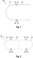
- Fig. 1 shows a section of an exemplary vessel 100.
- the vessel 100 is for storing a pressurized fluid.
- the vessel 100 may be used to receive and/or store various pressurized fluids, such as liquids, gases, cryogenic fluids or liquids, or the like.
- the vessel 100 may be used in an aircraft 10 (see Fig. 7 ) or a spacecraft for storing a pressurized fluid, wherein the application and/or use of the vessel 100 is not limited herein.
- the vessel 100 comprises a first vessel part 110 and a second vessel part 120.
- the first vessel part 110 and the second vessel part 120 are joined together at a circumferential joint portion 130.
- the vessel 100 further comprises a stiffener 140 arranged inside the vessel 100 to overlap the joint portion 130 and a respective joint end of each of the first vessel part 110 and the second vessel part 120.
- the stiffener 140 is configured to join the first vessel part 110 and the second vessel part 120 together by an adhesive 150.
- the stiffener 140 may be arranged in a surface manner on the respective first vessel part 110 and second vessel part 120.
- the adhesive 150 may be disposed between respective surfaces thereof.
- first vessel part 110 and/or the second vessel part 120 may be formed from a fiber composite material.
- first vessel part 110 and/or second vessel part 120 may be formed from a carbon fiber-reinforced polymer (CFRP), or any other fiber composite material capable of withholding pressurized fluids.
- CFRP carbon fiber-reinforced polymer
- the stiffener 140 is configured to reinforce the joint portion 130 from inside the vessel 100.
- the stiffener 140 is arranged and/or configured to allow application of force on the joint portion 130 during a bonding process using the adhesive 150.
- the stiffener 140 extends over the joint portion 130, i.e. overlaps it, and further overlaps the respective joint end of the first and second vessel part 110, 120.
- the adhesive 150 is applied and/or arranged between the stiffener 140 and the first vessel part 110 and/or second vessel part 120, thereby joining the first and second vessel parts 110, 120 together. It is noted that the adhesive 150 may also be arranged or present between the first and second vessel part 110, 120.
- the stiffener 140 as shown in Fig. 1 U-cross-section.
- a shape and/or cross-section of the stiffener 140 may be selected from a flat band, a U-cross-section, an L-cross-section, a T-cross-section, or the like. Further, the stiffener 140 may be formed with continuous material and/or as a closed ring. In addition, the stiffener 140 may be formed from a fiber composite material. For example, the stiffener 140 may be formed from a carbon fiber-reinforced polymer (CFRP), or any other fiber composite material capable of withholding pressurized fluids. Optionally, the stiffener 140 may be formed conically to at least one side facing the respective first vessel part 110 and/or second vessel part 120.
- CFRP carbon fiber-reinforced polymer
- the vessel 100 may further comprise a strip-shaped band 160 arranged outside the vessel, e.g. an outer band, to overlap the joint portion and a respective joint end of each of the first vessel part and the second vessel part.
- the band 160 e.g. outer band, may be arranged opposite to the stiffener 140.
- the band 160 may comprise the same, similar, or different dimensions as the stiffener 140.
- the band 160 may be formed from a carbon fiber-reinforced polymer (CFRP), or any other fiber composite material capable of withholding pressurized fluids.
- the band 160 may be formed from a multidirectional carbon fiber-reinforced material.
- the vessel 100 may further comprise one or more inner systems (not shown), such as, for example, pipes, sloshing walls, cables, sensing means, or the like, arranged inside the vessel 100. These may be installed before joining the vessel parts.
- inner systems such as, for example, pipes, sloshing walls, cables, sensing means, or the like, arranged inside the vessel 100. These may be installed before joining the vessel parts.
- the respective joint end of at least one of the first vessel part 110 and the second vessel part 120 may be formed conically.
- respective ends of the stiffener 140 may be formed conically.
- Fig. 2 illustrates the vessel 100 of Fig. 1 as a whole.
- the vessel 100 may be formed cylindrically with opposing domes at its ends.
- the vessel 100 may further comprise a third vessel part 110' that is at least similar or identical to the first vessel part 110 and, on a side of the second vessel part 120 facing away from the first vessel part 110, is joined together with the second vessel part 120 at a further joint portion 130' by a further stiffener 140' and a respective adhesive 150'.
- Fig. 3 illustrates a schematic sectional view of the joint portion 130 of the vessel 100.
- the stiffener 140 is arranged inside the vessel 100 to overlap the joint portion 130 and a respective joint end of each of the first vessel part 110 and the second vessel part 120.
- the stiffener 140 is configured to join the first vessel part 110 and the second vessel part 120 together by using the adhesive 150. It is noted that the arrangements of the adhesive 150 are merely exemplary, and that adhesive may be arranged or applied at more or fewer locations, or at other locations.
- At least one spacer 170 may be arranged locally between the stiffener 140 and the respective first and/or second vessel part 110, 120.
- the at least one spacer 170 may be effective in lateral or radial direction.
- the at least one spacer may be applied locally.
- the at least one spacer 170 may be configured to or may be used to provide a respective, defined gap for the adhesive 150.
- the gap may be used to allow injection of the adhesive 150 into the gap after joining the vessel parts 110, 120, 110', or to apply the adhesive 150 first and then move the vessel parts 110, 120, 110'towards each other without shifting the adhesive 150 away.
- Fig. 4 illustrates a section of the schematic sectional view of Fig. 3 in an enlarged manner, wherein the above-described gap(s) are better apparent here.
- Fig. 5 illustrates a schematic sectional view of a further example of the joint portion 130 of the vessel 100.
- the stiffener 140, the first vessel part 110 and/or the second vessel part 120 may be angled.
- the stiffener 140 may be roof shaped. In this way, the angled and/or conically formed joint ends may be brought together, e.g. moved towards each other, without shifting the adhesive 150 away. If the first vessel part 110 and/or second vessel part 120 have a respectively angled joint end, they may be moved over the stiffener 140 and the contact with the adhesive 150 is only in the final moment of the joining operation.
- Fig. 6 illustrates in a flow chart an exemplary method 200 for manufacturing a vessel, e.g. the above vessel 100.
- the method 200 comprises arranging 210 a first vessel part 110 and a second vessel part 120 on a stiffener 140 that the first vessel part 110 and the second vessel part 120 are supported, in a circumferential joint portion 130, by the stiffener 140 from inside the vessel 100. Thereby, the stiffener 140 overlaps the joint portion 130 and a respective joint end of each of the first vessel part 110 and the second vessel part 120.
- the method further comprises providing 220 an adhesive to join the first vessel part 110 and the second vessel part 120 together.
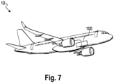
- Fig. 7 illustrates an exemplary aircraft 10 comprising the above vessel 100.
- the vessel 100 may be used for storing a pressurized fluid.
Landscapes
- Engineering & Computer Science (AREA)
- Mechanical Engineering (AREA)
- General Engineering & Computer Science (AREA)
- Standing Axle, Rod, Or Tube Structures Coupled By Welding, Adhesion, Or Deposition (AREA)
Abstract
Description
- The present invention relates to a vessel for storing a pressurized fluid. Further, the present invention relates to a method for manufacturing such vessel. In addition, the present invention relates to the use of such vessel in an aircraft or spacecraft, and an aircraft comprising such vessel.
- For storing pressurized fluids, such as liquids, gases or the like, vessels may be used. Such vessel may be designed to withstand positive pressure loads, tension, etc., and/or vacuum pressure and flight loads. In at least some cases, it may be desired to install an inner system, such as, for example, pipes, sloshing walls, cables, sensing means, or the like, inside the vessel.
- For example,
EP 4 124 790 A1 describes a hydrogen tank for aircrafts, which tank comprises an inner vessel for storing hydrogen and an outer jacket comprising cylindrical outer jackets and outer jacket domes. The cylindrical outer jackets and outer jacket domes are joined together at L-shaped ends by using fasteners distributed in a staggered pattern. -
EP 4 107 420 A1 describes a composite tank for storing a cryogenic propellant. The tank comprises a sealing casing and a reinforcing layer. - It would be desirable to provide, with constructively simple means, a vessel that allows installation of an inner system and still is capable of storing pressurized fluids.
- It is therefore an object of the present invention to provide a vessel for storing a pressurized fluid that allows installation of an inner system inside the vessel.
- This object is solved by the subject-matter of the appended independent claims. Further embodiments are defined in the appended dependent claims.
- According to a first aspect, there is provided a vessel for storing a pressurized fluid. The vessel comprises a first vessel part and a second vessel part, joined together at a circumferential joint portion. The vessel further comprises a stiffener arranged inside the vessel to overlap the joint portion and a respective joint end of each of the first vessel part and the second vessel part, and to join the first vessel part and the second vessel part together by an adhesive.
- In the provided vessel, the stiffener is configured to join two parts of the vessel by the stiffener arranged inside the two vessel parts. In this way, the stiffener reinforces the joint, i.e. the joint portion, so that forces, loads, etc. can be applied onto the vessel and/or the joint without deforming the whole vessel too much. This also improves the bonding quality of the two vessel parts and reduces the risk of gaps, cavities, or the like in the joint and failure of the bonding. At the same time, the vessel is composed of or may be split into multiple parts, i.e. at least the first vessel part and the second vessel part, to allow installation of one or more inner systems, such as, for example, pipes, sloshing walls, cables, sensing means, or the like, inside the vessel. Further, the manufacturing of the vessel with this configuration is particularly simple because the provision and/or preparation of the vessel parts and the stiffener as well as the bonding by the adhesive are simple in terms of manufacturing technology. Also, only adhesive is needed for the bonding. Using the adhesive for the bonding of the vessel parts allows tolerances of the first and second vessel part to be at least partially compensated.
- For example, the first vessel part may be an end part of the vessel. For instance, the first vessel part may have the shape of a dome or the like. Further, the second vessel part may be a middle or center part of the vessel. For instance, the second vessel part may be cylindrical, hemispherical, spherical, or the like, wherein these shapes are only exemplary and other shapes may also withstand pressure and may thus be suitable. The first and second vessel parts may be brought together or close together with respective joint faces, i.e. the respective joint ends, thereby defining the joint portion.
- The stiffener is configured to reinforce the joint portion from inside the vessel. The stiffener is arranged and/or configured to allow application of force on the joint portion during the bonding process. For this, the stiffener extends over the joint portion, i.e. overlaps it, and further overlaps the respective joint end of the first and second vessel part. The adhesive is applied and/or arranged between the stiffener and the first vessel part and/or second vessel part, thereby joining the first and second vessel parts together. From a functional perspective, the stiffener may also be referred to as a tool, as it is used to form the bonding in joint portion. After the bonding process, the stiffener used as a tool remains in the vessel as reinforcement. If the vessel is used in an aircraft, for example, the stiffener may also be referred to as a tool that travels with the aircraft.
- By way of example, the vessel may be a stand-alone tank, container or the like, or may be part of a tank, such as a double-walled tank, in which the vessel may form the inner tank. However, it may also be conceivable that the principle underlying the proposed vessel may be applied to the outer tank of such double-walled tank. Accordingly, at least some embodiments may also refer to a double-walled tank with the vessel disclosed herein as part of the tank, for example, as the inner tank.
- The adhesive does not have to meet any special requirements, so that in principle any adhesive may be used that is configured to be bonded to the respective material of the first vessel part, second vessel part and/or stiffener.
- The provided vessel may be used to receive and/or store various fluids, such as liquids, gases, cryogenic fluids or liquids, or the like. For example, hydrogen, nitrogen, or the like may be stored, to name just a few examples. In an aircraft, the vessel may be used, for example, to store low-emission fuels or the like. However, it is noted that the vessel may also be used on the ground, etc. for a wide variety of applications in which a pressurized fluid is to be stored.
- According to an embodiment, the first vessel part, the second vessel part and the stiffener may form a double-shear connection. In other words, the joint portion may be configured to allow simultaneous shear across two, e.g. parallel, planes. In this way, the vessel can be subjected to high forces, loads, etc., or may be able to withstand them.
- In an embodiment, the stiffener may be arranged in a surface manner on the respective first vessel part and second vessel part. The adhesive may be disposed between respective surfaces thereof. In this way, the vessel can be subjected to high forces, loads, etc., or may be able to withstand them. Further, manufacturing of the vessel may be simple.
- According to an embodiment, the stiffener may be formed with continuous material and/or as a closed ring. In this way, the vessel can be subjected to high forces, loads, etc., or may be able to withstand them. Further, manufacturing of the vessel may be simple. Diffusion of the fluid to be stored in the vessel may be reduced or avoided.
- In an embodiment, the stiffener may be formed from a fiber composite material. For example, the stiffener may be formed from a carbon fiber-reinforced polymer (CFRP), or any other fiber composite material capable of withholding pressurized fluids.
- According to an embodiment, a shape and/or cross-section of the stiffener may be selected from a flat shape, a U-cross-section, an L-cross-section, and a T-cross-section. In case of a flat shape, the stiffener may be band shaped, for example. Depending on mechanical load to be withstand, other shapes and/or cross-sections are also conceivable.
- In an embodiment, the stiffener may be formed conically to at least one side facing the respective first vessel part and/or second vessel part. In this way, the respective first vessel part and/or second vessel part may be pushed on the stiffener and may squeeze the adhesive. For this, the respective first vessel part and/or second vessel part may be formed conically accordingly. Alternatively or additionally, in at least some embodiments, the stiffener may be angled.
- According to an embodiment, the respective joint end of at least one of the first vessel part and the second vessel part may be angled. Alternatively and/or additionally, the respective joint end of at least one of the first vessel part and the second vessel part may be formed conically. In this way, the angled and/or conically formed joint ends may be brought together, e.g. moved towards each other, without shifting the adhesive away. If the first vessel part and/or second vessel part have a respectively angled joint end, they may be moved over the stiffener and the contact with the adhesive is only in the final moment of the joining operation.
- In an embodiment, at least one spacer may be arranged locally between the stiffener and the respective first and/or second vessel part. The spacer may be effective in lateral or radial direction. For example, the at least one spacer may be applied locally. The at least one spacer may be configured to or may be used to provide a defined gap for the adhesive. The gap may be used to allow injection of the adhesive into the gap after joining the vessel parts, or to apply the adhesive first and then move the vessel parts towards each other without shifting the adhesive away.
- According to an embodiment, the vessel may further comprise a strip-shaped band arranged outside the vessel, e.g. an outer band, to overlap the joint portion and a respective joint end of each of the first vessel part and the second vessel part. The band, e.g. outer band, may be arranged opposite to the stiffener. The band may comprise the same, similar or different dimensions as the stiffener. For example, the outer band may be formed from a carbon fiber-reinforced polymer (CFRP), or any other fiber composite material capable of withholding pressurized fluids. Also, the outer band may be formed from a multidirectional carbon fiber-reinforced material.
- In an embodiment, the first vessel part and/or the second vessel part may be formed from a fiber composite material. For example, the first vessel part and/or second vessel part may be formed from a carbon fiber-reinforced polymer (CFRP), or any other fiber composite material capable of withholding pressurized fluids.
- According to an embodiment, the principle disclosed herein may be applied to further vessel parts. In other words, the vessel may comprise more than the first vessel part and second vessel part, wherein the one or more further vessel parts may be joined to the first vessel part and/or second vessel part by using a further joint portion and/or a further stiffener. In at least some embodiments, the vessel may further comprise a third vessel part that is at least similar or identical to the first vessel part and, on a side of the second vessel part facing away from the first vessel part, is joined together with the second vessel part at a further joint portion by a further stiffener and a respective adhesive. In this way, a, for example, cylindrical vessel comprising domes at its ends may be provided.
- According to a further aspect, there is provided a method for manufacturing a vessel for storing a pressurized fluid. The method may be carried out to manufacture the vessel of the first aspect and/or one or more of the above embodiments. The method comprises arranging a first vessel part and a second vessel part on a stiffener that the first vessel part and the second vessel part are supported, in a circumferential joint portion, by the stiffener from inside the vessel. The stiffener overlaps the joint portion and a respective joint end of each of the first vessel part and the second vessel part. The method further comprises providing an adhesive to join the first vessel part and the second vessel part together.
- In the proposed method, the stiffener first serves as a tool for facilitating the joining and/or bonding process of the first and second vessel part. Then, during the use of the vessel, the stiffener, remaining inside the vessel, further serves for reinforcing the joint portion and/or the joined vessel parts. It then contributes, for example, to mechanical reinforcement, joint portion sealing, etc.
- According to an embodiment, the stiffener, the first vessel part and/or the second vessel part may be formed conical at the respective joint end, and in case of the stiffener at one or both ends. In this way, the first and/or second vessel part may be pushed on the stiffener and squeeze the adhesive.
- In an embodiment, the stiffener, the first vessel part and/or the second vessel part may be angled, and in case of the stiffener may be roof shaped. In this way, the angled and/or conically formed joint ends may be brought together, e.g. moved towards each other, without shifting the adhesive away. If the first vessel part and/or second vessel part have a respectively angled joint end, they may be moved over the stiffener and the contact with the adhesive is only in the final moment of the joining operation.
- According to an embodiment, the method may further comprise activating and/or curing of the adhesive.
- For example, the adhesive may be inserted into the joint portion to at least partially compensate for tolerances of the first and/or second vessel part.
- In an embodiment, at least one spacer may be arranged locally between the stiffener and the respective first and/or second vessel part. The spacer may be effective in lateral or radial direction. For example, the at least one spacer may be applied locally. The at least one spacer may be configured to or may be used to provide a defined gap for the adhesive. The gap may be used to allow injection of the adhesive into the gap after joining the vessel parts, or to apply the adhesive first and then move the vessel parts towards each other without shifting the adhesive away.
- According to an embodiment, the adhesive may be injected into the joint portion from outside when the first and/or second vessel part is already arranged on the stiffener. Alternatively or additionally, the adhesive may be injected or injected in part before both of the first and second vessel parts are arranged on the stiffener.
- In an embodiment, the stiffener may be formed with continuous material and/or as a closed ring. In this way, manufacturing of the vessel may be simple, as the first vessel part and the second vessel part can be easily arranged on the stiffener.
- Another aspect relates to the use of a vessel according to the first aspect and/or manufactured with the above method, in an aircraft or spacecraft for storing a pressurized fluid.
- According to a further aspect, there is provided an aircraft or spacecraft, comprising a vessel according to the first aspect and/or manufactured in accordance with the above method.
- The invention will be explained in greater detail with reference to exemplary embodiments depicted in the drawings as appended.
- The present invention is explained in more detail below with reference to the embodiments shown in the schematic figures:
- Fig. 1
- illustrates a section of an exemplary vessel according to an embodiment.
- Fig. 2
- illustrates an exemplary vessel according to an embodiment.
- Fig. 3
- illustrates a schematic sectional view of an exemplary joint portion of a vessel according to an embodiment.
- Fig. 4
- illustrates a section of the schematic sectional view of
Fig. 3 in an enlarged manner. - Fig. 5
- illustrates a schematic sectional view of an exemplary joint portion of a vessel according to an embodiment.
- Fig. 6
- illustrates in a flow chart an exemplary method for manufacturing a vessel according to an embodiment.
- Fig. 7
- illustrates an exemplary aircraft comprising a vessel according to an embodiment.
- In the figures of the drawing, elements, features and components which are identical, functionally identical and of identical action are denoted in each case by the same reference designations unless stated otherwise.
-
Fig. 1 shows a section of anexemplary vessel 100. Thevessel 100 is for storing a pressurized fluid. Thevessel 100 may be used to receive and/or store various pressurized fluids, such as liquids, gases, cryogenic fluids or liquids, or the like. Merly by way of example, thevessel 100 may be used in an aircraft 10 (seeFig. 7 ) or a spacecraft for storing a pressurized fluid, wherein the application and/or use of thevessel 100 is not limited herein. - The
vessel 100 comprises afirst vessel part 110 and asecond vessel part 120. Thefirst vessel part 110 and thesecond vessel part 120 are joined together at a circumferentialjoint portion 130. Thevessel 100 further comprises astiffener 140 arranged inside thevessel 100 to overlap thejoint portion 130 and a respective joint end of each of thefirst vessel part 110 and thesecond vessel part 120. Thestiffener 140 is configured to join thefirst vessel part 110 and thesecond vessel part 120 together by an adhesive 150. - For example, the
stiffener 140 may be arranged in a surface manner on the respectivefirst vessel part 110 andsecond vessel part 120. The adhesive 150 may be disposed between respective surfaces thereof. - For example, the
first vessel part 110 may be an end part of thevessel 100. For instance, thefirst vessel part 110 may have the shape of a dome or the like. Further, thesecond vessel part 120 may be a middle or center part of thevessel 100. For instance, thesecond vessel 120 part may be cylindrical, hemispherical, spherical, or the like, wherein these shapes are only exemplary and other shapes may also withstand pressure and may thus be suitable. The first andsecond vessel parts joint portion 130. - Further, by way of example, the
first vessel part 110 and/or thesecond vessel part 120 may be formed from a fiber composite material. For example, thefirst vessel part 110 and/orsecond vessel part 120 may be formed from a carbon fiber-reinforced polymer (CFRP), or any other fiber composite material capable of withholding pressurized fluids. - The
stiffener 140 is configured to reinforce thejoint portion 130 from inside thevessel 100. Thestiffener 140 is arranged and/or configured to allow application of force on thejoint portion 130 during a bonding process using the adhesive 150. For this, thestiffener 140 extends over thejoint portion 130, i.e. overlaps it, and further overlaps the respective joint end of the first andsecond vessel part stiffener 140 and thefirst vessel part 110 and/orsecond vessel part 120, thereby joining the first andsecond vessel parts second vessel part stiffener 140 as shown inFig. 1 U-cross-section. However, it is noted that a shape and/or cross-section of thestiffener 140 may be selected from a flat band, a U-cross-section, an L-cross-section, a T-cross-section, or the like. Further, thestiffener 140 may be formed with continuous material and/or as a closed ring. In addition, thestiffener 140 may be formed from a fiber composite material. For example, thestiffener 140 may be formed from a carbon fiber-reinforced polymer (CFRP), or any other fiber composite material capable of withholding pressurized fluids. Optionally, thestiffener 140 may be formed conically to at least one side facing the respectivefirst vessel part 110 and/orsecond vessel part 120. - Optionally, the
vessel 100 may further comprise a strip-shapedband 160 arranged outside the vessel, e.g. an outer band, to overlap the joint portion and a respective joint end of each of the first vessel part and the second vessel part. Theband 160, e.g. outer band, may be arranged opposite to thestiffener 140. Theband 160 may comprise the same, similar, or different dimensions as thestiffener 140. For example, theband 160 may be formed from a carbon fiber-reinforced polymer (CFRP), or any other fiber composite material capable of withholding pressurized fluids. Also, theband 160 may be formed from a multidirectional carbon fiber-reinforced material. - It is noted that, optionally, the
vessel 100 may further comprise one or more inner systems (not shown), such as, for example, pipes, sloshing walls, cables, sensing means, or the like, arranged inside thevessel 100. These may be installed before joining the vessel parts. - Further, it is noted that, optionally, the respective joint end of at least one of the
first vessel part 110 and thesecond vessel part 120 may be formed conically. Likewise, optionally, respective ends of thestiffener 140 may be formed conically. -
Fig. 2 illustrates thevessel 100 ofFig. 1 as a whole. Accordingly, thevessel 100 may be formed cylindrically with opposing domes at its ends. Thevessel 100 may further comprise a third vessel part 110' that is at least similar or identical to thefirst vessel part 110 and, on a side of thesecond vessel part 120 facing away from thefirst vessel part 110, is joined together with thesecond vessel part 120 at a further joint portion 130' by a further stiffener 140' and a respective adhesive 150'. -
Fig. 3 illustrates a schematic sectional view of thejoint portion 130 of thevessel 100. As described above, thefirst vessel part 110 and thesecond vessel part 120 are joined together in or at the circumferentialjoint portion 130. Thestiffener 140 is arranged inside thevessel 100 to overlap thejoint portion 130 and a respective joint end of each of thefirst vessel part 110 and thesecond vessel part 120. Thestiffener 140 is configured to join thefirst vessel part 110 and thesecond vessel part 120 together by using the adhesive 150. It is noted that the arrangements of the adhesive 150 are merely exemplary, and that adhesive may be arranged or applied at more or fewer locations, or at other locations. - As exemplary illustrated in
Fig. 3 , optionally, at least onespacer 170 may be arranged locally between thestiffener 140 and the respective first and/orsecond vessel part spacer 170 may be effective in lateral or radial direction. For example, the at least one spacer may be applied locally. The at least onespacer 170 may be configured to or may be used to provide a respective, defined gap for the adhesive 150. The gap may be used to allow injection of the adhesive 150 into the gap after joining thevessel parts vessel parts -
Fig. 4 illustrates a section of the schematic sectional view ofFig. 3 in an enlarged manner, wherein the above-described gap(s) are better apparent here. -
Fig. 5 illustrates a schematic sectional view of a further example of thejoint portion 130 of thevessel 100. Accordingly, thestiffener 140, thefirst vessel part 110 and/or thesecond vessel part 120 may be angled. For example, thestiffener 140 may be roof shaped. In this way, the angled and/or conically formed joint ends may be brought together, e.g. moved towards each other, without shifting the adhesive 150 away. If thefirst vessel part 110 and/orsecond vessel part 120 have a respectively angled joint end, they may be moved over thestiffener 140 and the contact with the adhesive 150 is only in the final moment of the joining operation. -
Fig. 6 illustrates in a flow chart anexemplary method 200 for manufacturing a vessel, e.g. theabove vessel 100. Themethod 200 comprises arranging 210 afirst vessel part 110 and asecond vessel part 120 on astiffener 140 that thefirst vessel part 110 and thesecond vessel part 120 are supported, in a circumferentialjoint portion 130, by thestiffener 140 from inside thevessel 100. Thereby, thestiffener 140 overlaps thejoint portion 130 and a respective joint end of each of thefirst vessel part 110 and thesecond vessel part 120. The method further comprises providing 220 an adhesive to join thefirst vessel part 110 and thesecond vessel part 120 together. -
Fig. 7 illustrates an exemplary aircraft 10 comprising theabove vessel 100. In theaircraft 100, thevessel 100 may be used for storing a pressurized fluid. - In the foregoing detailed description, various features are grouped together in one or more examples or examples with the purpose of streamlining the disclosure. It is to be understood that the above description is intended to be illustrative, and not restrictive. It is intended to cover all alternatives, modifications and equivalents. Many other examples will be apparent to one skilled in the art upon reviewing the above specification. The embodiments were chosen and described in order to best explain the principles of the invention and its practical applications, to thereby enable others skilled in the art to best utilize the invention and various embodiments with various modifications as are suited to the particular use contemplated.
-
- 100
- vessel
- 110
- first vessel part
- 120
- second vessel part
- 130
- joint portion
- 140
- stiffener
- 150
- adhesive
- 160
- band (e.g. outer band)
- 170
- spacer
- 200
- method
- 210
- method step
- 220
- method step
- 10
- aircraft
Claims (15)
- A vessel (100) for storing a pressurized fluid, the vessel comprising:a first vessel part (110) and a second vessel part (120), joined together at a circumferential joint portion (130); anda stiffener (140) arranged inside the vessel (100) to overlap the joint portion (130) and a respective joint end of each of the first vessel part (110) and the second vessel part (120), and to join the first vessel part (110) and the second vessel part (120) together by an adhesive (150).
- The vessel of claim 1, wherein the first vessel part (110), the second vessel part (120) and the stiffener (130) form a double-shear connection.
- The vessel of claim 1 or 2, wherein the stiffener (140) is arranged in a surface manner on the respective first vessel part (110) and second vessel part (120), and the adhesive (150) is disposed between respective surfaces thereof.
- The vessel of any one of the preceding claims, wherein the stiffener (140) is formed with continuous material and/or as a closed ring.
- The vessel of any one of the preceding claims, wherein the stiffener (140) is formed from a fiber composite material.
- The vessel of any one of the preceding claims, wherein a shape and/or cross-section of the stiffener (140) is selected from a flat shape, a U-cross-section, an L-cross-section, and a T-cross-section.
- The vessel of any one of the preceding claims, wherein the stiffener (140) is formed conically to at least one side facing the respective first vessel part (110) and/or second vessel part (120), and/or angled.
- The vessel of any one of the preceding claims, wherein the respective joint end of at least one of the first vessel part (110) and the second vessel part (120) is formed conically and/or is angled.
- The vessel of any one of the preceding claims, wherein at least one spacer is arranged locally between the stiffener and the respective first and/or second vessel part and effective in lateral or radial direction.
- The vessel of any one of the preceding claims, further comprising a strip-shaped band arranged outside the vessel (100) to overlap the joint portion (130) and a respective joint end of each of the first vessel part (110) and the second vessel part (120).
- The vessel of any one of the preceding claims, wherein the first vessel part (110) and/or the second vessel part is formed from a fiber composite material.
- The vessel of any one of the preceding claims, further comprising a third vessel part (110') that is at least similar or identical to the first vessel part (110) and, on a side of the second vessel part (120) facing away from the first vessel part (110), is joined together with the second vessel part (120) at a further joint portion (130') by a further stiffener (140') and a respective adhesive (150').
- A method (200) for manufacturing a vessel (100) for storing a pressurized fluid, the method comprising:arranging (210) a first vessel part (110) and a second vessel part (120) on a stiffener (140) that the first vessel part (110) and the second vessel part (120) are supported, in a circumferential joint portion (130), by the stiffener (140) from inside the vessel (100);wherein the stiffener (140) overlaps the joint portion (130) and a respective joint end of each of the first vessel part (110) and the second vessel part (120); andproviding (220) an adhesive to join the first vessel part (110) and the second vessel part (120) together.
- The use of a vessel (100) according to any one of the preceding claims in an aircraft (10) or spacecraft for storing a pressurized fluid.
- An aircraft (10), comprising a vessel according to any one of claims 1 to 12.
Priority Applications (1)
| Application Number | Priority Date | Filing Date | Title |
|---|---|---|---|
| EP23198170.5A EP4528143A1 (en) | 2023-09-19 | 2023-09-19 | Vessel for storing a pressurized fluid |
Applications Claiming Priority (1)
| Application Number | Priority Date | Filing Date | Title |
|---|---|---|---|
| EP23198170.5A EP4528143A1 (en) | 2023-09-19 | 2023-09-19 | Vessel for storing a pressurized fluid |
Publications (1)
| Publication Number | Publication Date |
|---|---|
| EP4528143A1 true EP4528143A1 (en) | 2025-03-26 |
Family
ID=88098146
Family Applications (1)
| Application Number | Title | Priority Date | Filing Date |
|---|---|---|---|
| EP23198170.5A Withdrawn EP4528143A1 (en) | 2023-09-19 | 2023-09-19 | Vessel for storing a pressurized fluid |
Country Status (1)
| Country | Link |
|---|---|
| EP (1) | EP4528143A1 (en) |
Citations (6)
| Publication number | Priority date | Publication date | Assignee | Title |
|---|---|---|---|---|
| US4304038A (en) * | 1977-09-26 | 1981-12-08 | Nippon Aluminium Mfg. Co., Ltd. | Method of manufacturing small-sized pressure vessel of sheet metal |
| US20040026431A1 (en) * | 2002-01-18 | 2004-02-12 | Jones Brian H | Low weight high performance composite vessel and method of making same |
| US20070205201A1 (en) * | 2002-04-12 | 2007-09-06 | Microcosm, Inc. | Composite pressure tank and process for its manufacture |
| US7743940B2 (en) * | 2003-02-18 | 2010-06-29 | Magna Steyr Fahrezeugtechnik AG & Co. KG | Double-walled container having supports for positioning the inner and outer walls |
| EP4107420A1 (en) | 2020-02-17 | 2022-12-28 | Centre National d'Études Spatiales | Tank for cryogenic propellants |
| EP4124790A1 (en) | 2021-07-27 | 2023-02-01 | Airbus Operations, S.L.U. | Hydrogen tank for aircrafts |
-
2023
- 2023-09-19 EP EP23198170.5A patent/EP4528143A1/en not_active Withdrawn
Patent Citations (6)
| Publication number | Priority date | Publication date | Assignee | Title |
|---|---|---|---|---|
| US4304038A (en) * | 1977-09-26 | 1981-12-08 | Nippon Aluminium Mfg. Co., Ltd. | Method of manufacturing small-sized pressure vessel of sheet metal |
| US20040026431A1 (en) * | 2002-01-18 | 2004-02-12 | Jones Brian H | Low weight high performance composite vessel and method of making same |
| US20070205201A1 (en) * | 2002-04-12 | 2007-09-06 | Microcosm, Inc. | Composite pressure tank and process for its manufacture |
| US7743940B2 (en) * | 2003-02-18 | 2010-06-29 | Magna Steyr Fahrezeugtechnik AG & Co. KG | Double-walled container having supports for positioning the inner and outer walls |
| EP4107420A1 (en) | 2020-02-17 | 2022-12-28 | Centre National d'Études Spatiales | Tank for cryogenic propellants |
| EP4124790A1 (en) | 2021-07-27 | 2023-02-01 | Airbus Operations, S.L.U. | Hydrogen tank for aircrafts |
Similar Documents
| Publication | Publication Date | Title |
|---|---|---|
| US11559964B2 (en) | Composite structures, composite storage tanks, vehicles including such composite storage tanks, and related systems and methods | |
| US5085343A (en) | Nested tank construction | |
| EP0664418A1 (en) | Pressure vessel with system to prevent liner separation | |
| US11845602B2 (en) | Tank and method | |
| US8974135B2 (en) | Fabric preform insert for a composite tank Y-joint | |
| EP4043716B1 (en) | Inner composite frame multi-joined barrel, shell-integrated projectile propellant tank including same, and method for manufacturing same | |
| US8939407B2 (en) | Common bulkhead for composite propellant tanks | |
| US6499287B1 (en) | Integrated tankage for propulsion vehicles and the like | |
| EP3279090B1 (en) | Composite joint | |
| KR20050039603A (en) | High pressure container and method for manufacturing the same | |
| US20030093987A1 (en) | Integrated tankage for propulsion vehicles and the like | |
| Johnson et al. | Structures and design phase I summary for the NASA composite cryotank technology demonstration project | |
| EP3556688B1 (en) | Low-temperature tank and method for manufacturing same | |
| US12135111B2 (en) | Hydrogen tank for aircraft | |
| EP0557907A1 (en) | Assembly and method for attaching a pressure vessel to another object | |
| US6082676A (en) | Cryogenic tanks for launch vehicles | |
| EP4174359B1 (en) | Hydrogen tank, method for cooling hydrogen tank, and hydrogen drive vehicle and hydrogen tank | |
| US6361055B1 (en) | Cryogenic composite tank seals | |
| EP4286737B1 (en) | Composite hydrogen tank for an aircraft | |
| Fink et al. | Hybrid titanium composite material improving composite structure coupling | |
| EP2836760B1 (en) | Composite tank having joint with softening strip and method of making the tank | |
| EP4402379B1 (en) | Lightweight composite actuator | |
| KR102925865B1 (en) | Method for Producing a Pressure Tank with Composite Materials | |
| Faddoul | Structural considerations in design of lightweight glass-fiber composite pressure vessels | |
| Torano et al. | Current study status of the advanced technologies for the JI upgrade launch vehicle-Cryogenic composite tank |
Legal Events
| Date | Code | Title | Description |
|---|---|---|---|
| PUAI | Public reference made under article 153(3) epc to a published international application that has entered the european phase |
Free format text: ORIGINAL CODE: 0009012 |
|
| STAA | Information on the status of an ep patent application or granted ep patent |
Free format text: STATUS: THE APPLICATION HAS BEEN PUBLISHED |
|
| AK | Designated contracting states |
Kind code of ref document: A1 Designated state(s): AL AT BE BG CH CY CZ DE DK EE ES FI FR GB GR HR HU IE IS IT LI LT LU LV MC ME MK MT NL NO PL PT RO RS SE SI SK SM TR |
|
| STAA | Information on the status of an ep patent application or granted ep patent |
Free format text: STATUS: REQUEST FOR EXAMINATION WAS MADE |
|
| 17P | Request for examination filed |
Effective date: 20250926 |
|
| STAA | Information on the status of an ep patent application or granted ep patent |
Free format text: STATUS: THE APPLICATION IS DEEMED TO BE WITHDRAWN |
|
| 18D | Application deemed to be withdrawn |
Effective date: 20250927 |