EP4528086A1 - Device and method for controlling oxygen storage amount in three-way catalyst - Google Patents
Device and method for controlling oxygen storage amount in three-way catalyst Download PDFInfo
- Publication number
- EP4528086A1 EP4528086A1 EP22941873.6A EP22941873A EP4528086A1 EP 4528086 A1 EP4528086 A1 EP 4528086A1 EP 22941873 A EP22941873 A EP 22941873A EP 4528086 A1 EP4528086 A1 EP 4528086A1
- Authority
- EP
- European Patent Office
- Prior art keywords
- fuel ratio
- flow rate
- catalytic converter
- air fuel
- way catalytic
- Prior art date
- Legal status (The legal status is an assumption and is not a legal conclusion. Google has not performed a legal analysis and makes no representation as to the accuracy of the status listed.)
- Withdrawn
Links
Images

Classifications
-
- F—MECHANICAL ENGINEERING; LIGHTING; HEATING; WEAPONS; BLASTING
- F01—MACHINES OR ENGINES IN GENERAL; ENGINE PLANTS IN GENERAL; STEAM ENGINES
- F01N—GAS-FLOW SILENCERS OR EXHAUST APPARATUS FOR MACHINES OR ENGINES IN GENERAL; GAS-FLOW SILENCERS OR EXHAUST APPARATUS FOR INTERNAL-COMBUSTION ENGINES
- F01N3/00—Exhaust or silencing apparatus having means for purifying, rendering innocuous, or otherwise treating exhaust
- F01N3/08—Exhaust or silencing apparatus having means for purifying, rendering innocuous, or otherwise treating exhaust for rendering innocuous
- F01N3/10—Exhaust or silencing apparatus having means for purifying, rendering innocuous, or otherwise treating exhaust for rendering innocuous by thermal or catalytic conversion of noxious components of exhaust
- F01N3/18—Exhaust or silencing apparatus having means for purifying, rendering innocuous, or otherwise treating exhaust for rendering innocuous by thermal or catalytic conversion of noxious components of exhaust characterised by methods of operation; Control
- F01N3/22—Control of additional air supply only, e.g. using by-passes or variable air pump drives
-
- F—MECHANICAL ENGINEERING; LIGHTING; HEATING; WEAPONS; BLASTING
- F01—MACHINES OR ENGINES IN GENERAL; ENGINE PLANTS IN GENERAL; STEAM ENGINES
- F01N—GAS-FLOW SILENCERS OR EXHAUST APPARATUS FOR MACHINES OR ENGINES IN GENERAL; GAS-FLOW SILENCERS OR EXHAUST APPARATUS FOR INTERNAL-COMBUSTION ENGINES
- F01N3/00—Exhaust or silencing apparatus having means for purifying, rendering innocuous, or otherwise treating exhaust
- F01N3/08—Exhaust or silencing apparatus having means for purifying, rendering innocuous, or otherwise treating exhaust for rendering innocuous
- F01N3/10—Exhaust or silencing apparatus having means for purifying, rendering innocuous, or otherwise treating exhaust for rendering innocuous by thermal or catalytic conversion of noxious components of exhaust
- F01N3/101—Three-way catalysts
-
- F—MECHANICAL ENGINEERING; LIGHTING; HEATING; WEAPONS; BLASTING
- F01—MACHINES OR ENGINES IN GENERAL; ENGINE PLANTS IN GENERAL; STEAM ENGINES
- F01N—GAS-FLOW SILENCERS OR EXHAUST APPARATUS FOR MACHINES OR ENGINES IN GENERAL; GAS-FLOW SILENCERS OR EXHAUST APPARATUS FOR INTERNAL-COMBUSTION ENGINES
- F01N2560/00—Exhaust systems with means for detecting or measuring exhaust gas components or characteristics
- F01N2560/02—Exhaust systems with means for detecting or measuring exhaust gas components or characteristics the means being an exhaust gas sensor
- F01N2560/025—Exhaust systems with means for detecting or measuring exhaust gas components or characteristics the means being an exhaust gas sensor for measuring or detecting O2, e.g. lambda sensors
-
- F—MECHANICAL ENGINEERING; LIGHTING; HEATING; WEAPONS; BLASTING
- F01—MACHINES OR ENGINES IN GENERAL; ENGINE PLANTS IN GENERAL; STEAM ENGINES
- F01N—GAS-FLOW SILENCERS OR EXHAUST APPARATUS FOR MACHINES OR ENGINES IN GENERAL; GAS-FLOW SILENCERS OR EXHAUST APPARATUS FOR INTERNAL-COMBUSTION ENGINES
- F01N2900/00—Details of electrical control or of the monitoring of the exhaust gas treating apparatus
- F01N2900/06—Parameters used for exhaust control or diagnosing
- F01N2900/16—Parameters used for exhaust control or diagnosing said parameters being related to the exhaust apparatus, e.g. particulate filter or catalyst
- F01N2900/1624—Catalyst oxygen storage capacity
-
- Y—GENERAL TAGGING OF NEW TECHNOLOGICAL DEVELOPMENTS; GENERAL TAGGING OF CROSS-SECTIONAL TECHNOLOGIES SPANNING OVER SEVERAL SECTIONS OF THE IPC; TECHNICAL SUBJECTS COVERED BY FORMER USPC CROSS-REFERENCE ART COLLECTIONS [XRACs] AND DIGESTS
- Y02—TECHNOLOGIES OR APPLICATIONS FOR MITIGATION OR ADAPTATION AGAINST CLIMATE CHANGE
- Y02T—CLIMATE CHANGE MITIGATION TECHNOLOGIES RELATED TO TRANSPORTATION
- Y02T10/00—Road transport of goods or passengers
- Y02T10/10—Internal combustion engine [ICE] based vehicles
- Y02T10/12—Improving ICE efficiencies
Definitions
- the present invention relates to a method and a device for suitably controlling a quantity of oxygen stored in a three-way catalytic converter provided in an exhaust passage of an internal combustion engine.
- a three-way catalytic converter is capable of oxidizing CO and HC and reducing NOx.
- the catalytic converter has a capability to store and release oxygen, which is known as oxygen storage capability.
- a technique is known in which a quantity of oxygen stored in a three-way catalytic converter is monitored, and a target air fuel ratio for air fuel ratio feedback control is variably controlled so as to maintain the stored oxygen quantity at an intermediate target value (e.g., 50%).
- a patent document 1 discloses that, based on a load and rotational speed of an internal combustion engine, a target stored oxygen quantity is set to be relatively small under operating conditions that result in high NOx emissions, and is set to be relatively large under operating conditions that result in high CO and HC emissions.
- an optimal target stored oxygen quantity correlates with a flow rate of gas flowing into a three-way catalytic converter.
- the flow rate of gas flowing through the three-way catalytic converter is large, the gas passing through a catalytic layer of the three-way catalytic converter has a high flow velocity, and thereby raises a slip rate of NOx, wherein the slip rate is a proportion of NOx that passes through without being converted. Therefore, it is desirable to lower a quantity of oxygen stored in the three-way catalytic converter as the gas flow rate increases.
- Patent document 1 is silent about such control of a stored oxygen quantity in relation to a gas flow rate.
- Patent Document 1 Japanese Patent Application Publication No. 2000-008921
- a method for controlling a quantity of oxygen stored in a three-way catalytic converter of an internal combustion engine includes: feedback-controlling an air fuel ratio of the internal combustion engine in accordance with an air fuel ratio setpoint in vicinity of a stoichiometric point; controlling the air fuel ratio setpoint so as to conform the quantity of stored oxygen to a target value; and setting the target value of the quantity of stored oxygen in accordance with a flow rate of gas entering the three-way catalytic converter such that the target value decreases as the flow rate of gas increases.
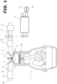
- FIG. 1 is an explanatory diagram showing a schematic configuration of an internal combustion engine 1 according to the embodiment of the present invention.
- the internal combustion engine 1 is a four-stroke cycle spark ignition internal combustion engine (a so-called gasoline engine), and includes cylinders each of which is provided with an intake valve 2, an exhaust valve 3, and an ignition plug 4.
- the internal combustion engine 1 is configured as an incylinder direct injection type in which a fuel injection valve 5 is arranged closer to the intake valve 2 for injecting fuel into the cylinder.
- the internal combustion engine 1 may be configured as a port injection type in which fuel is injected toward an intake port 6.
- An electronically controlled throttle valve 10 is interposed upstream of a collector section 8 of an intake passage 7 which is connected to the intake port 6 of each cylinder.
- the opening of the throttle valve 10 is controlled by a control signal from an engine controller 9.
- An air flow meter 11 is disposed upstream of the throttle valve 10 for sensing a quantity of intake air.
- An air cleaner 12 is disposed upstream of the airflow meter 11.
- Each cylinder includes an exhaust port 13 joined with the other exhaust ports 13 to form a single exhaust passage 14.
- the exhaust passage 14 is provided with a three-way catalytic converter 15 for purifying exhaust gas.
- the three-way catalytic converter 15 is a so-called monolithic ceramic catalytic converter in which a catalytic layer containing a catalytic metal is coated on a surface of a monolithic ceramic body having fine passages formed therein.
- the three-way catalytic converter 15 may be configured to include a plurality of catalytic converters arranged in series (for example, a manifold catalytic converter and an underfloor catalytic converter).
- an air fuel ratio sensor 19 is disposed on the inlet side of the three-way catalytic converter 15 in the exhaust passage 14, that is, disposed upstream of the three-way catalytic converter 15 in the exhaust passage 14.
- the air fuel ratio sensor 19 is a so-called wide-range air fuel ratio sensor that provides an output in accordance with the exhaust air fuel ratio.
- a second air fuel ratio sensor such as an O2 sensor, may be further provided downstream of the three-way catalytic converter 15 for calibrating an air fuel ratio feedback control system including the air fuel ratio sensor 19, diagnosing deterioration of the three-way catalytic converter 15, etc.
- Sensing signals from the air fuel ratio sensor 19 and the air flow meter 11 are inputted to the engine controller 9.
- the engine controller 9 further receives input of sensing signals from multiple sensors and the like, such as a crank angle sensor 21 for sensing engine speed, a water temperature sensor 22 for sensing a cooling water temperature, and an accelerator opening sensor 23 for sensing an amount of depression of an accelerator pedal operated by a driver. Based on these input signals, the engine controller 9 optimally controls a quantity and a timing of fuel injection performed by the fuel injection valve 5, a timing of ignition performed by the spark plug 4, the opening of the throttle valve 10, and others.
- the engine controller 9 performs an air fuel ratio control as one of various controls for the internal combustion engine 1, wherein the air fuel ratio control is intended for optimizing exhaust purification performance of the three-way catalytic converter 15.
- the air fuel ratio control is a feedback control (for example, PID control) of the fuel injection quantity based on the exhaust air fuel ratio sensed by the air fuel ratio sensor 19, for conforming the air fuel ratio to a target air fuel ratio near the stoichiometric air fuel ratio.
- the target air fuel ratio is controlled so as to conform a stored oxygen quantity of the three-way catalytic converter 15 to a target stored oxygen quantity, wherein the stored oxygen quantity is estimated from the exhaust air fuel ratio.
- FIG. 2 is an explanatory diagram showing a flow of the air fuel ratio control based on the stored oxygen quantity, in a form like a flowchart.
- the intake air quantity sensed by the air flow meter 11 is inputted as a parameter corresponding to a flow rate of gas flowing into the three-way catalytic converter 15.
- "intake air quantity” does not mean a quantity of air per cylinder cycle, but means a flow rate of air taken into the internal combustion engine 1 (i.e., passing through the air flow meter 11) per unit time.
- Step S1 the exhaust air fuel ratio (catalytic converter inlet air fuel ratio) sensed by the air fuel ratio sensor 19 is inputted.
- Step S1 the stored oxygen quantity of the three-way catalytic converter 15 is estimated based on the exhaust air fuel ratio sensed by the air fuel ratio sensor 19 and the flow rate of gas flowing into the three-way catalytic converter 15, i.e., the intake air quantity. This estimation is implemented by increasing or reducing the stored oxygen quantity depending on a value of the exhaust air fuel ratio at the moment at each cycle of calculation of the engine controller 9.
- estimate stored oxygen quantity a value of the stored oxygen quantity at the moment is estimated by integrating both positive and negative values. This quantity is henceforth referred to as "estimated stored oxygen quantity".
- a target stored oxygen quantity is set based on the flow rate of gas flowing into the three-way catalytic converter 15, i.e., the intake air quantity.
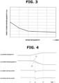
- FIG. 3 shows characteristics of the target stored oxygen quantity with respect to the intake air quantity.
- the engine controller 9 is provided with characteristics as shown in FIG. 3 in the form of a table, wherein the target stored oxygen quantity is outputted with respect to input of the intake air quantity.
- the target stored oxygen quantity has a characteristic that the target stored oxygen quantity decreases as the intake air quantity increases.
- a relationship is characterized in that the target stored oxygen quantity relatively rapidly decreases with respect to increase in the intake air quantity in a region where the intake air quantity is relatively small, and the target stored oxygen quantity relatively slowly decreases with respect to increase in the intake air quantity in a region where the intake air quantity is relatively large (a region on the right side of FIG. 3 ).
- the target stored oxygen quantity obtained at Step S2 is compared with the estimated stored oxygen quantity obtained at Step S1 to determine a difference therebetween.
- the target air fuel ratio (the target air fuel ratio on the inlet side of the three-way catalytic converter 15) is calculated using the value of difference and the flow rate of gas flowing into the three-way catalytic converter 15, i.e., the intake air quantity.
- the target air fuel ratio is controlled to be richer than the stoichiometric air fuel ratio.
- the target air fuel ratio is set taking account of the gas flow rate, i.e., the intake air quantity, so that the stored oxygen quantity changes at a suitable speed.
- Step S5 the difference between the target air fuel ratio obtained at Step S4 and the exhaust air fuel ratio sensed by the air fuel ratio sensor 19 (i.e., the actual air fuel ratio) is calculated, and a feedback compensation amount for the fuel injection quantity is outputted by a feedback control such as PID control. Finally, the quantity of fuel injected from the fuel injection valve 5 for each cycle is corrected by this feedback compensation amount.
- FIG. 4 is a time chart showing an example of changes in the target stored oxygen quantity and others under the control according to the embodiment described above.
- FIG. 4 shows, from the top to the bottom, (a) the intake air quantity, (b) the stored oxygen quantity, (c) the target air fuel ratio, and (d) an actual air fuel ratio.
- the section (b) for the stored oxygen quantity shows the estimated stored oxygen quantity b1 and the target stored oxygen quantity b2 which overlap each other.
- the intake air quantity is constant until a time instant t1, and gradually increases during a period from the time instant t1 to a time instant t3.
- the estimated stored oxygen quantity b1 and the target stored oxygen quantity b2 in the stored oxygen quantity section are identical to each other until the time instant t1.
- the target stored oxygen quantity b2 starts to decrease and deviates from the estimated stored oxygen quantity b1.
- the target air fuel ratio changes to the rich side at a time instant t2 as shown in the section (c).
- the target air fuel ratio has a constant value close to the stoichiometric air fuel ratio in this example.
- the target air fuel ratio changes to the rich side, so that the fuel injection quantity is feedback-controlled to increase, and the actual air fuel ratio changes to the rich side as shown in the section (d). Accordingly, the estimated stored oxygen quantity b1 also gradually decreases.
- FIG. 4 is an explanatory time chart for explaining behavior according to the embodiment described above, and does not necessarily accurately depict actual waveforms. For example, for the period from the time instant t1 to the time instant t2, a delay due to a calculation cycle is exaggerated.
- the target stored oxygen quantity of the three-way catalytic converter 15 is controlled based on the intake air quantity, i.e., the flow rate of gas flowing into the three-way catalytic converter 15, wherein when the gas flow rate is large, the stored oxygen quantity is controlled to be relatively low.
- the flow rate of gas flowing into the three-way catalytic converter 15 is large, the flow rate of gas passing through the catalytic layer of the three-way catalytic converter 15 increases, so that the slip rate of NOx tends to increase.
- the stored oxygen quantity is controlled to be relatively low, thereby cancelling the increase in the slip rate of NOx caused by the increase in gas flow velocity, and thereby purifying NOx more reliably.
- the intake air quantity is used as a parameter corresponding to the flow rate of gas flowing into the three-way catalytic converter 15.
- the exhaust gas flow rate may be calculated based on the intake air quantity, taking account of combustion.
- the exhaust flow rate of gas flowing through the exhaust passage may be sensed by some means.
- the intake air quantity may be a mass flow rate or a volume flow rate.
- the relationship between the target stored oxygen quantity and the intake air quantity shown in FIG. 3 may be set suitable for the mass flow rate or volume flow rate.
Landscapes
- Engineering & Computer Science (AREA)
- Chemical & Material Sciences (AREA)
- Health & Medical Sciences (AREA)
- Chemical Kinetics & Catalysis (AREA)
- Toxicology (AREA)
- Combustion & Propulsion (AREA)
- Mechanical Engineering (AREA)
- General Engineering & Computer Science (AREA)
- Materials Engineering (AREA)
- Electrical Control Of Air Or Fuel Supplied To Internal-Combustion Engine (AREA)
- Exhaust Gas After Treatment (AREA)
Abstract
Description
- The present invention relates to a method and a device for suitably controlling a quantity of oxygen stored in a three-way catalytic converter provided in an exhaust passage of an internal combustion engine.
- Where exhaust gas contains CO, HC, and NOx, a three-way catalytic converter is capable of oxidizing CO and HC and reducing NOx. In order to allow catalytic action thereof to achieve high levels of oxidation and reduction, it is important that the catalytic converter has a capability to store and release oxygen, which is known as oxygen storage capability. In relation to this viewpoint, a technique is known in which a quantity of oxygen stored in a three-way catalytic converter is monitored, and a target air fuel ratio for air fuel ratio feedback control is variably controlled so as to maintain the stored oxygen quantity at an intermediate target value (e.g., 50%).
- Furthermore, a
patent document 1 discloses that, based on a load and rotational speed of an internal combustion engine, a target stored oxygen quantity is set to be relatively small under operating conditions that result in high NOx emissions, and is set to be relatively large under operating conditions that result in high CO and HC emissions. - According to new findings by the present inventors, an optimal target stored oxygen quantity correlates with a flow rate of gas flowing into a three-way catalytic converter. When the flow rate of gas flowing through the three-way catalytic converter is large, the gas passing through a catalytic layer of the three-way catalytic converter has a high flow velocity, and thereby raises a slip rate of NOx, wherein the slip rate is a proportion of NOx that passes through without being converted. Therefore, it is desirable to lower a quantity of oxygen stored in the three-way catalytic converter as the gas flow rate increases.
-
Patent document 1 is silent about such control of a stored oxygen quantity in relation to a gas flow rate. - Patent Document 1:
Japanese Patent Application Publication No. 2000-008921 - According to the present invention, a method for controlling a quantity of oxygen stored in a three-way catalytic converter of an internal combustion engine, wherein the three-way catalytic converter is arranged in an exhaust passage of the internal combustion engine, includes: feedback-controlling an air fuel ratio of the internal combustion engine in accordance with an air fuel ratio setpoint in vicinity of a stoichiometric point; controlling the air fuel ratio setpoint so as to conform the quantity of stored oxygen to a target value; and setting the target value of the quantity of stored oxygen in accordance with a flow rate of gas entering the three-way catalytic converter such that the target value decreases as the flow rate of gas increases.
- The setting that the target value of the stored oxygen quantity decreases as the flow rate of gas entering the three-way catalytic converter increases, serves to cancel an increase in slip rate of NOx caused by an increase in gas flow velocity, and thereby purify NOx more reliably.
-
-
FIG. 1 is a diagram illustrating configuration of an internal combustion engine equipped with a three-way catalytic converter according to an embodiment of the present invention. -
FIG. 2 is an explanatory diagram showing a control flow according to the embodiment. -
FIG. 3 is a characteristic diagram showing characteristics of a target stored oxygen quantity with respect to an intake air quantity. -
FIG. 4 is a time chart showing an example of changes in (a) the intake air quantity, (b) a stored oxygen quantity, (c) a target air fuel ratio, and (d) an actual air fuel ratio. - The following describes an embodiment of the present invention in detail with reference to the drawings.
FIG. 1 is an explanatory diagram showing a schematic configuration of aninternal combustion engine 1 according to the embodiment of the present invention. Theinternal combustion engine 1 is a four-stroke cycle spark ignition internal combustion engine (a so-called gasoline engine), and includes cylinders each of which is provided with anintake valve 2, anexhaust valve 3, and an ignition plug 4. In the illustrated example, theinternal combustion engine 1 is configured as an incylinder direct injection type in which afuel injection valve 5 is arranged closer to theintake valve 2 for injecting fuel into the cylinder. Alternatively, theinternal combustion engine 1 may be configured as a port injection type in which fuel is injected toward anintake port 6. - An electronically controlled throttle valve 10 is interposed upstream of a
collector section 8 of anintake passage 7 which is connected to theintake port 6 of each cylinder. The opening of the throttle valve 10 is controlled by a control signal from anengine controller 9. Anair flow meter 11 is disposed upstream of the throttle valve 10 for sensing a quantity of intake air. Anair cleaner 12 is disposed upstream of theairflow meter 11. - Each cylinder includes an
exhaust port 13 joined with theother exhaust ports 13 to form asingle exhaust passage 14. Theexhaust passage 14 is provided with a three-waycatalytic converter 15 for purifying exhaust gas. In this example, the three-waycatalytic converter 15 is a so-called monolithic ceramic catalytic converter in which a catalytic layer containing a catalytic metal is coated on a surface of a monolithic ceramic body having fine passages formed therein. The three-waycatalytic converter 15 may be configured to include a plurality of catalytic converters arranged in series (for example, a manifold catalytic converter and an underfloor catalytic converter). - For sensing an exhaust air fuel ratio, an air
fuel ratio sensor 19 is disposed on the inlet side of the three-waycatalytic converter 15 in theexhaust passage 14, that is, disposed upstream of the three-waycatalytic converter 15 in theexhaust passage 14. The airfuel ratio sensor 19 is a so-called wide-range air fuel ratio sensor that provides an output in accordance with the exhaust air fuel ratio. A second air fuel ratio sensor, such as an O2 sensor, may be further provided downstream of the three-waycatalytic converter 15 for calibrating an air fuel ratio feedback control system including the airfuel ratio sensor 19, diagnosing deterioration of the three-waycatalytic converter 15, etc. - Sensing signals from the air
fuel ratio sensor 19 and theair flow meter 11 are inputted to theengine controller 9. Theengine controller 9 further receives input of sensing signals from multiple sensors and the like, such as acrank angle sensor 21 for sensing engine speed, awater temperature sensor 22 for sensing a cooling water temperature, and anaccelerator opening sensor 23 for sensing an amount of depression of an accelerator pedal operated by a driver. Based on these input signals, theengine controller 9 optimally controls a quantity and a timing of fuel injection performed by thefuel injection valve 5, a timing of ignition performed by the spark plug 4, the opening of the throttle valve 10, and others. - The
engine controller 9 performs an air fuel ratio control as one of various controls for theinternal combustion engine 1, wherein the air fuel ratio control is intended for optimizing exhaust purification performance of the three-waycatalytic converter 15. The air fuel ratio control is a feedback control (for example, PID control) of the fuel injection quantity based on the exhaust air fuel ratio sensed by the airfuel ratio sensor 19, for conforming the air fuel ratio to a target air fuel ratio near the stoichiometric air fuel ratio. The target air fuel ratio is controlled so as to conform a stored oxygen quantity of the three-waycatalytic converter 15 to a target stored oxygen quantity, wherein the stored oxygen quantity is estimated from the exhaust air fuel ratio. -
FIG. 2 is an explanatory diagram showing a flow of the air fuel ratio control based on the stored oxygen quantity, in a form like a flowchart. At operations shown as Steps S1, S2, and S4, the intake air quantity sensed by theair flow meter 11 is inputted as a parameter corresponding to a flow rate of gas flowing into the three-waycatalytic converter 15. It is to be noted that "intake air quantity" does not mean a quantity of air per cylinder cycle, but means a flow rate of air taken into the internal combustion engine 1 (i.e., passing through the air flow meter 11) per unit time. Furthermore, at the operation shown as Step S1 and an operation shown as Step S5, the exhaust air fuel ratio (catalytic converter inlet air fuel ratio) sensed by the airfuel ratio sensor 19 is inputted. At Step S1, the stored oxygen quantity of the three-waycatalytic converter 15 is estimated based on the exhaust air fuel ratio sensed by the airfuel ratio sensor 19 and the flow rate of gas flowing into the three-waycatalytic converter 15, i.e., the intake air quantity. This estimation is implemented by increasing or reducing the stored oxygen quantity depending on a value of the exhaust air fuel ratio at the moment at each cycle of calculation of theengine controller 9. Put simply, when the exhaust air fuel ratio of the exhaust gas flowing into the three-waycatalytic converter 15 is lean, the stored oxygen quantity increases, and when the exhaust air fuel ratio is rich, the stored oxygen quantity decreases. Accordingly, a value of the stored oxygen quantity at the moment is estimated by integrating both positive and negative values. This quantity is henceforth referred to as "estimated stored oxygen quantity". - At Step S2, a target stored oxygen quantity is set based on the flow rate of gas flowing into the three-way
catalytic converter 15, i.e., the intake air quantity.FIG. 3 shows characteristics of the target stored oxygen quantity with respect to the intake air quantity. In this example, theengine controller 9 is provided with characteristics as shown inFIG. 3 in the form of a table, wherein the target stored oxygen quantity is outputted with respect to input of the intake air quantity. As shown inFIG. 3 , the target stored oxygen quantity has a characteristic that the target stored oxygen quantity decreases as the intake air quantity increases. Specifically, between the intake air quantity and the target stored oxygen quantity, a relationship is characterized in that the target stored oxygen quantity relatively rapidly decreases with respect to increase in the intake air quantity in a region where the intake air quantity is relatively small, and the target stored oxygen quantity relatively slowly decreases with respect to increase in the intake air quantity in a region where the intake air quantity is relatively large (a region on the right side ofFIG. 3 ). - At Step S3, the target stored oxygen quantity obtained at Step S2 is compared with the estimated stored oxygen quantity obtained at Step S1 to determine a difference therebetween.
- This value of difference is one of inputs to the operation of Step S4. At Step S4, the target air fuel ratio (the target air fuel ratio on the inlet side of the three-way catalytic converter 15) is calculated using the value of difference and the flow rate of gas flowing into the three-way
catalytic converter 15, i.e., the intake air quantity. For example, when the estimated stored oxygen quantity is greater than the target stored oxygen quantity, the target air fuel ratio is controlled to be richer than the stoichiometric air fuel ratio. When the flow rate of gas flowing into the three-waycatalytic converter 15 is large, the decrease in the stored oxygen quantity caused by enriching the air fuel ratio becomes relatively rapid. Therefore, the target air fuel ratio is set taking account of the gas flow rate, i.e., the intake air quantity, so that the stored oxygen quantity changes at a suitable speed. - At Step S5, the difference between the target air fuel ratio obtained at Step S4 and the exhaust air fuel ratio sensed by the air fuel ratio sensor 19 (i.e., the actual air fuel ratio) is calculated, and a feedback compensation amount for the fuel injection quantity is outputted by a feedback control such as PID control. Finally, the quantity of fuel injected from the
fuel injection valve 5 for each cycle is corrected by this feedback compensation amount. -
FIG. 4 is a time chart showing an example of changes in the target stored oxygen quantity and others under the control according to the embodiment described above.FIG. 4 shows, from the top to the bottom, (a) the intake air quantity, (b) the stored oxygen quantity, (c) the target air fuel ratio, and (d) an actual air fuel ratio. The section (b) for the stored oxygen quantity shows the estimated stored oxygen quantity b1 and the target stored oxygen quantity b2 which overlap each other. - In this example time chart, the intake air quantity is constant until a time instant t1, and gradually increases during a period from the time instant t1 to a time instant t3. The estimated stored oxygen quantity b1 and the target stored oxygen quantity b2 in the stored oxygen quantity section are identical to each other until the time instant t1. When the intake air quantity starts to increase at the time instant t1, the target stored oxygen quantity b2 starts to decrease and deviates from the estimated stored oxygen quantity b1.
- In accordance with the difference between the target stored oxygen quantity b2 and the estimated stored oxygen quantity b1, the target air fuel ratio changes to the rich side at a time instant t2 as shown in the section (c). Until the time instant t2, the target air fuel ratio has a constant value close to the stoichiometric air fuel ratio in this example. At the time instant t2, the target air fuel ratio changes to the rich side, so that the fuel injection quantity is feedback-controlled to increase, and the actual air fuel ratio changes to the rich side as shown in the section (d). Accordingly, the estimated stored oxygen quantity b1 also gradually decreases.
- It is to be noted that
FIG. 4 is an explanatory time chart for explaining behavior according to the embodiment described above, and does not necessarily accurately depict actual waveforms. For example, for the period from the time instant t1 to the time instant t2, a delay due to a calculation cycle is exaggerated. - According to the embodiment described above, the target stored oxygen quantity of the three-way
catalytic converter 15 is controlled based on the intake air quantity, i.e., the flow rate of gas flowing into the three-waycatalytic converter 15, wherein when the gas flow rate is large, the stored oxygen quantity is controlled to be relatively low. When the flow rate of gas flowing into the three-waycatalytic converter 15 is large, the flow rate of gas passing through the catalytic layer of the three-waycatalytic converter 15 increases, so that the slip rate of NOx tends to increase. In the embodiment described above, the stored oxygen quantity is controlled to be relatively low, thereby cancelling the increase in the slip rate of NOx caused by the increase in gas flow velocity, and thereby purifying NOx more reliably. - Although one embodiment of the present invention has been described above, the present invention is not limited to the embodiment described above and various modifications are possible. For example, in the embodiment described above, the intake air quantity is used as a parameter corresponding to the flow rate of gas flowing into the three-way
catalytic converter 15. However, the exhaust gas flow rate may be calculated based on the intake air quantity, taking account of combustion. Alternatively, the exhaust flow rate of gas flowing through the exhaust passage may be sensed by some means. - In the embodiment described above, the intake air quantity may be a mass flow rate or a volume flow rate. For example, the relationship between the target stored oxygen quantity and the intake air quantity shown in
FIG. 3 may be set suitable for the mass flow rate or volume flow rate.
Claims (4)
- A method for controlling a quantity of oxygen stored in a three-way catalytic converter of an internal combustion engine, wherein the three-way catalytic converter is arranged in an exhaust passage of the internal combustion engine, the method comprising:feedback-controlling an air fuel ratio of the internal combustion engine in accordance with an air fuel ratio setpoint in vicinity of a stoichiometric point;controlling the air fuel ratio setpoint so as to conform the quantity of stored oxygen to a target value; andsetting the target value of the quantity of stored oxygen in accordance with a flow rate of gas entering the three-way catalytic converter such that the target value decreases as the flow rate of gas increases.
- The method as claimed in claim 1, wherein the setting of the target value of the quantity of stored oxygen is implemented by setting the target value such that the target value relatively rapidly decreases with respect to increase in the flow rate of gas in a region where the flow rate of gas is relatively small, and the target value relatively slowly decreases with respect to increase in the flow rate of gas in a region where the flow rate of gas is relatively large.
- The method as claimed in claim 1, comprising substituting a flow rate of intake air of the internal combustion engine for the flow rate of gas.
- A device for controlling a quantity of oxygen stored in a three-way catalytic converter of an internal combustion engine, the device comprising:the three-way catalytic converter being arranged in an exhaust passage of the internal combustion engine;an air fuel ratio sensor disposed on an inlet side of the three-way catalytic converter; anda controller configured to control a fuel injection quantity;wherein the controller is further configured to:feedback-control an air fuel ratio of the internal combustion engine in accordance with an air fuel ratio setpoint in vicinity of a stoichiometric point;control the air fuel ratio setpoint so as to conform the quantity of stored oxygen to a target value; andset the target value of the quantity of stored oxygen in accordance with a flow rate of gas entering the three-way catalytic converter such that the target value decreases as the flow rate of gas increases.
Applications Claiming Priority (1)
| Application Number | Priority Date | Filing Date | Title |
|---|---|---|---|
| PCT/JP2022/020843 WO2023223504A1 (en) | 2022-05-19 | 2022-05-19 | Device and method for controlling oxygen storage amount in three-way catalyst |
Publications (1)
| Publication Number | Publication Date |
|---|---|
| EP4528086A1 true EP4528086A1 (en) | 2025-03-26 |
Family
ID=88834931
Family Applications (1)
| Application Number | Title | Priority Date | Filing Date |
|---|---|---|---|
| EP22941873.6A Withdrawn EP4528086A1 (en) | 2022-05-19 | 2022-05-19 | Device and method for controlling oxygen storage amount in three-way catalyst |
Country Status (4)
| Country | Link |
|---|---|
| EP (1) | EP4528086A1 (en) |
| JP (1) | JP7718589B2 (en) |
| CN (1) | CN119213205A (en) |
| WO (1) | WO2023223504A1 (en) |
Family Cites Families (7)
| Publication number | Priority date | Publication date | Assignee | Title |
|---|---|---|---|---|
| JP2843879B2 (en) * | 1993-01-22 | 1999-01-06 | 本田技研工業株式会社 | Catalyst deterioration detection device for internal combustion engine |
| JP3939026B2 (en) | 1998-06-17 | 2007-06-27 | 株式会社日立製作所 | Three-way catalyst oxygen storage control device |
| JP4264760B2 (en) * | 2007-04-09 | 2009-05-20 | 三菱自動車工業株式会社 | Exhaust gas purification device for internal combustion engine |
| JP2010169020A (en) * | 2009-01-23 | 2010-08-05 | Nissan Motor Co Ltd | Exhaust emission control device |
| US9273593B2 (en) * | 2010-12-24 | 2016-03-01 | Toyota Jidosha Kabushiki Kaisha | Control apparatus for internal combustion engine |
| JP6094438B2 (en) * | 2013-09-27 | 2017-03-15 | トヨタ自動車株式会社 | Control device for internal combustion engine |
| EP4538508A1 (en) * | 2022-06-10 | 2025-04-16 | Nissan Motor Co., Ltd. | Control method and control device for internal combustion engine |
-
2022
- 2022-05-19 JP JP2024521485A patent/JP7718589B2/en active Active
- 2022-05-19 CN CN202280096106.9A patent/CN119213205A/en active Pending
- 2022-05-19 EP EP22941873.6A patent/EP4528086A1/en not_active Withdrawn
- 2022-05-19 WO PCT/JP2022/020843 patent/WO2023223504A1/en not_active Ceased
Also Published As
| Publication number | Publication date |
|---|---|
| CN119213205A (en) | 2024-12-27 |
| JPWO2023223504A1 (en) | 2023-11-23 |
| WO2023223504A1 (en) | 2023-11-23 |
| JP7718589B2 (en) | 2025-08-05 |
Similar Documents
| Publication | Publication Date | Title |
|---|---|---|
| US5784880A (en) | Engine fuel supply control device | |
| JP4733002B2 (en) | Exhaust gas purification device for internal combustion engine | |
| US5285639A (en) | Method and system for controlling secondary air for internal combustion engine | |
| JPS62162746A (en) | Air-fuel ratio control device | |
| US8224553B2 (en) | Method and device for operating an internal combustion engine | |
| JP2004257377A (en) | Exhaust purification device for internal combustion engine | |
| US6644275B2 (en) | Apparatus for controlling engine | |
| JP7718589B2 (en) | Method and device for controlling oxygen storage amount of three-way catalyst | |
| EP4582678B1 (en) | Air-fuel ratio control method and device for internal combustion engine | |
| JPH07151000A (en) | Air-fuel ratio controller for internal combustion engine | |
| JP4299218B2 (en) | Air-fuel ratio control device for internal combustion engine | |
| JP2008121518A (en) | Exhaust gas purification device for internal combustion engine | |
| JP7493885B2 (en) | Control device for internal combustion engine | |
| JPS582443A (en) | Engine air-fuel control | |
| JPS6345444A (en) | Air-fuel ratio controller for internal combustion engine | |
| JP3879342B2 (en) | Exhaust gas purification device for internal combustion engine | |
| JPH1193814A (en) | Ignition timing control device for internal combustion engine | |
| WO2025163844A1 (en) | Air–fuel ratio control method and device for internal combustion engine | |
| JP2023142713A (en) | Control device of internal combustion engine | |
| JPH0518235A (en) | Secondary air control device for internal combustion engine | |
| JP2017115802A (en) | Air fuel ratio controller for internal combustion engine | |
| JP2026038330A (en) | Control method and control device for internal combustion engine | |
| JPH0559935A (en) | Catalyst deterioration preventive device of internal combustion engine | |
| JP2022059350A (en) | Internal combustion engine control device | |
| JP2022133865A (en) | Control device for internal combustion engine |
Legal Events
| Date | Code | Title | Description |
|---|---|---|---|
| STAA | Information on the status of an ep patent application or granted ep patent |
Free format text: STATUS: THE INTERNATIONAL PUBLICATION HAS BEEN MADE |
|
| PUAI | Public reference made under article 153(3) epc to a published international application that has entered the european phase |
Free format text: ORIGINAL CODE: 0009012 |
|
| STAA | Information on the status of an ep patent application or granted ep patent |
Free format text: STATUS: REQUEST FOR EXAMINATION WAS MADE |
|
| 17P | Request for examination filed |
Effective date: 20241127 |
|
| AK | Designated contracting states |
Kind code of ref document: A1 Designated state(s): AL AT BE BG CH CY CZ DE DK EE ES FI FR GB GR HR HU IE IS IT LI LT LU LV MC MK MT NL NO PL PT RO RS SE SI SK SM TR |
|
| STAA | Information on the status of an ep patent application or granted ep patent |
Free format text: STATUS: THE APPLICATION HAS BEEN WITHDRAWN |
|
| 18W | Application withdrawn |
Effective date: 20250403 |