EP4528077A1 - Vane pump with kidney port configurations in port plates for balanced vanes - Google Patents
Vane pump with kidney port configurations in port plates for balanced vanes Download PDFInfo
- Publication number
- EP4528077A1 EP4528077A1 EP24201793.7A EP24201793A EP4528077A1 EP 4528077 A1 EP4528077 A1 EP 4528077A1 EP 24201793 A EP24201793 A EP 24201793A EP 4528077 A1 EP4528077 A1 EP 4528077A1
- Authority
- EP
- European Patent Office
- Prior art keywords
- kidney
- pressure
- discharge
- port
- inlet
- Prior art date
- Legal status (The legal status is an assumption and is not a legal conclusion. Google has not performed a legal analysis and makes no representation as to the accuracy of the status listed.)
- Withdrawn
Links
Images




Classifications
-
- F—MECHANICAL ENGINEERING; LIGHTING; HEATING; WEAPONS; BLASTING
- F04—POSITIVE - DISPLACEMENT MACHINES FOR LIQUIDS; PUMPS FOR LIQUIDS OR ELASTIC FLUIDS
- F04C—ROTARY-PISTON, OR OSCILLATING-PISTON, POSITIVE-DISPLACEMENT MACHINES FOR LIQUIDS; ROTARY-PISTON, OR OSCILLATING-PISTON, POSITIVE-DISPLACEMENT PUMPS
- F04C2/00—Rotary-piston machines or pumps
- F04C2/30—Rotary-piston machines or pumps having the characteristics covered by two or more groups F04C2/02, F04C2/08, F04C2/22, F04C2/24 or having the characteristics covered by one of these groups together with some other type of movement between co-operating members
- F04C2/34—Rotary-piston machines or pumps having the characteristics covered by two or more groups F04C2/02, F04C2/08, F04C2/22, F04C2/24 or having the characteristics covered by one of these groups together with some other type of movement between co-operating members having the movement defined in groups F04C2/08 or F04C2/22 and relative reciprocation between the co-operating members
- F04C2/344—Rotary-piston machines or pumps having the characteristics covered by two or more groups F04C2/02, F04C2/08, F04C2/22, F04C2/24 or having the characteristics covered by one of these groups together with some other type of movement between co-operating members having the movement defined in groups F04C2/08 or F04C2/22 and relative reciprocation between the co-operating members with vanes reciprocating with respect to the inner member
- F04C2/3446—Rotary-piston machines or pumps having the characteristics covered by two or more groups F04C2/02, F04C2/08, F04C2/22, F04C2/24 or having the characteristics covered by one of these groups together with some other type of movement between co-operating members having the movement defined in groups F04C2/08 or F04C2/22 and relative reciprocation between the co-operating members with vanes reciprocating with respect to the inner member the inner and outer member being in contact along more than one line or surface
-
- F—MECHANICAL ENGINEERING; LIGHTING; HEATING; WEAPONS; BLASTING
- F04—POSITIVE - DISPLACEMENT MACHINES FOR LIQUIDS; PUMPS FOR LIQUIDS OR ELASTIC FLUIDS
- F04C—ROTARY-PISTON, OR OSCILLATING-PISTON, POSITIVE-DISPLACEMENT MACHINES FOR LIQUIDS; ROTARY-PISTON, OR OSCILLATING-PISTON, POSITIVE-DISPLACEMENT PUMPS
- F04C2/00—Rotary-piston machines or pumps
- F04C2/30—Rotary-piston machines or pumps having the characteristics covered by two or more groups F04C2/02, F04C2/08, F04C2/22, F04C2/24 or having the characteristics covered by one of these groups together with some other type of movement between co-operating members
- F04C2/34—Rotary-piston machines or pumps having the characteristics covered by two or more groups F04C2/02, F04C2/08, F04C2/22, F04C2/24 or having the characteristics covered by one of these groups together with some other type of movement between co-operating members having the movement defined in groups F04C2/08 or F04C2/22 and relative reciprocation between the co-operating members
- F04C2/344—Rotary-piston machines or pumps having the characteristics covered by two or more groups F04C2/02, F04C2/08, F04C2/22, F04C2/24 or having the characteristics covered by one of these groups together with some other type of movement between co-operating members having the movement defined in groups F04C2/08 or F04C2/22 and relative reciprocation between the co-operating members with vanes reciprocating with respect to the inner member
-
- F—MECHANICAL ENGINEERING; LIGHTING; HEATING; WEAPONS; BLASTING
- F01—MACHINES OR ENGINES IN GENERAL; ENGINE PLANTS IN GENERAL; STEAM ENGINES
- F01C—ROTARY-PISTON OR OSCILLATING-PISTON MACHINES OR ENGINES
- F01C21/00—Component parts, details or accessories not provided for in groups F01C1/00 - F01C20/00
- F01C21/10—Outer members for co-operation with rotary pistons; Casings
- F01C21/104—Stators; Members defining the outer boundaries of the working chamber
- F01C21/108—Stators; Members defining the outer boundaries of the working chamber with an axial surface, e.g. side plates
-
- F—MECHANICAL ENGINEERING; LIGHTING; HEATING; WEAPONS; BLASTING
- F04—POSITIVE - DISPLACEMENT MACHINES FOR LIQUIDS; PUMPS FOR LIQUIDS OR ELASTIC FLUIDS
- F04C—ROTARY-PISTON, OR OSCILLATING-PISTON, POSITIVE-DISPLACEMENT MACHINES FOR LIQUIDS; ROTARY-PISTON, OR OSCILLATING-PISTON, POSITIVE-DISPLACEMENT PUMPS
- F04C18/00—Rotary-piston pumps specially adapted for elastic fluids
- F04C18/30—Rotary-piston pumps specially adapted for elastic fluids having the characteristics covered by two or more of groups F04C18/02, F04C18/08, F04C18/22, F04C18/24, F04C18/48, or having the characteristics covered by one of these groups together with some other type of movement between co-operating members
- F04C18/34—Rotary-piston pumps specially adapted for elastic fluids having the characteristics covered by two or more of groups F04C18/02, F04C18/08, F04C18/22, F04C18/24, F04C18/48, or having the characteristics covered by one of these groups together with some other type of movement between co-operating members having the movement defined in group F04C18/08 or F04C18/22 and relative reciprocation between the co-operating members
- F04C18/344—Rotary-piston pumps specially adapted for elastic fluids having the characteristics covered by two or more of groups F04C18/02, F04C18/08, F04C18/22, F04C18/24, F04C18/48, or having the characteristics covered by one of these groups together with some other type of movement between co-operating members having the movement defined in group F04C18/08 or F04C18/22 and relative reciprocation between the co-operating members with vanes reciprocating with respect to the inner member
-
- F—MECHANICAL ENGINEERING; LIGHTING; HEATING; WEAPONS; BLASTING
- F04—POSITIVE - DISPLACEMENT MACHINES FOR LIQUIDS; PUMPS FOR LIQUIDS OR ELASTIC FLUIDS
- F04C—ROTARY-PISTON, OR OSCILLATING-PISTON, POSITIVE-DISPLACEMENT MACHINES FOR LIQUIDS; ROTARY-PISTON, OR OSCILLATING-PISTON, POSITIVE-DISPLACEMENT PUMPS
- F04C29/00—Component parts, details or accessories of pumps or pumping installations, not provided for in groups F04C18/00 - F04C28/00
- F04C29/12—Arrangements for admission or discharge of the working fluid, e.g. constructional features of the inlet or outlet
- F04C29/124—Arrangements for admission or discharge of the working fluid, e.g. constructional features of the inlet or outlet with inlet and outlet valves specially adapted for rotary or oscillating piston pumps
-
- F—MECHANICAL ENGINEERING; LIGHTING; HEATING; WEAPONS; BLASTING
- F01—MACHINES OR ENGINES IN GENERAL; ENGINE PLANTS IN GENERAL; STEAM ENGINES
- F01C—ROTARY-PISTON OR OSCILLATING-PISTON MACHINES OR ENGINES
- F01C21/00—Component parts, details or accessories not provided for in groups F01C1/00 - F01C20/00
- F01C21/08—Rotary pistons
- F01C21/0809—Construction of vanes or vane holders
- F01C21/0818—Vane tracking; control therefor
- F01C21/0854—Vane tracking; control therefor by fluid means
- F01C21/0863—Vane tracking; control therefor by fluid means the fluid being the working fluid
-
- F—MECHANICAL ENGINEERING; LIGHTING; HEATING; WEAPONS; BLASTING
- F04—POSITIVE - DISPLACEMENT MACHINES FOR LIQUIDS; PUMPS FOR LIQUIDS OR ELASTIC FLUIDS
- F04C—ROTARY-PISTON, OR OSCILLATING-PISTON, POSITIVE-DISPLACEMENT MACHINES FOR LIQUIDS; ROTARY-PISTON, OR OSCILLATING-PISTON, POSITIVE-DISPLACEMENT PUMPS
- F04C15/00—Component parts, details or accessories of machines, pumps or pumping installations, not provided for in groups F04C2/00 - F04C14/00
- F04C15/0042—Systems for the equilibration of forces acting on the machines or pump
Definitions
- the present disclosure relates to vane pumps, and more particularly to a vane pump employing radially pressure balanced vanes with improved durability features.
- vane pumps used straight vanes such as those described in U.S. Patent No. 6,634,865 .
- the geometry of the vanes can be altered from the traditional straight vanes, e.g., as shown and described in U.S. patent No. 7,637,724 .
- Each of these Patents is incorporated by reference herein in its entirety.
- a vane pump system includes a kidney port plate configured to be engaged at an axial end of a rotor and of a liner.
- the port plate is configured to be mounted stationary relative to the liner.
- the port kidney plate includes an over vane inlet port configured to be circumferentially aligned with an inlet arc segment of a circumferential cam surface of the liner for ingress of fluid to a plurality of vanes.
- the kidney port plate includes an over vane discharge port configured to be circumferentially aligned with a discharge arc segment of the circumferential cam surface for discharging pressurized fluid from the plurality of vanes.
- the kidney port plate includes at least six kidney ports radially inward from the over vane inlet port and the over vane discharge port.
- the kidney ports are circumferentially spaced apart from one another.
- the kidney ports are configured to be radially aligned with vane slots of the rotor for pressure balancing across over vane and under vane ends of the plurality of va
- the plurality of vanes can be made of tool steel.
- a first pressure regulated kidney port can be circumferentially adjacent to the first inlet kidney port.
- a first discharge kidney port can be circumferentially adjacent to the first pressure regulated kidney port.
- a second pressure regulated kidney port can be circumferentially adjacent to the first discharge kidney port.
- a second inlet kidney port can be circumferentially adjacent to the second pressure regulated kidney port.
- a third pressure regulated kidney port can be circumferentially adjacent to the second inlet kidney port.
- a second discharge kidney port can be circumferentially adjacent to the third pressure regulated kidney port.
- a fourth pressure regulated kidney port can be circumferentially adjacent to the second discharge kidney port.
- the first inlet kidney port can be circumferentially adjacent to the fourth pressure regulated kidney port.
- a first regulated pressure kidney port can be circumferentially adjacent to the first discharge kidney port.
- a second inlet kidney port can be circumferentially adjacent to the first regulated pressure kidney port.
- a second discharge kidney port can be circumferentially adjacent to the second inlet pressure kidney port.
- a second regulated pressure kidney port can be circumferentially adjacent to the second discharge kidney port.
- the first inlet kidney port can be circumferentially adjacent to the second regulated pressure kidney port.
- a pressure regulating valve (PRV) in a pressure balancing passage can be configured so pressure from discharge can be ported to the first and second regulated pressure kidney ports, wherein the PRV is configured to reduce pressure from the discharge to an intermediate pressure between inlet pressure and discharge pressure of the rotor to balance vane loading in the first and second pump arc segments and in the first and second seal arc segments.
- PRV pressure regulating valve
- the liner can have a bore extending therethrough and defines the circumferential cam surface of a pumping cavity, with a rotation axis defined in an axial direction through the bore.
- the circumferential cam surface can include the discharge arc segment, the inlet arc segment and a pump arc segment circumferentially separating the inlet arc segment and the discharge arc segment from one another.
- the rotor can be mounted for rotational movement within the bore of the liner about the rotation axis.
- the rotor can have a central body portion which includes the vane slots.
- the vane slots can be a plurality of circumferentially spaced apart radially extending vane slots formed in the rotor.
- Each vane slot can support a corresponding one of the vanes mounted for radial movement therein.
- Each of the vanes can have a radially outer tip surface adapted for slideably engaging the circumferential cam surface of the pumping cavity and a radially inner portion within each vane slot.
- the first pressure regulated kidney port can be circumferentially aligned with the pump arc segment.
- the inlet arc segment can be a first inlet arc segment.
- the second pressure regulated kidney port can be circumferentially aligned with a seal arc segment that is circumferentially between the discharge arc segment and a second inlet arc segment diametrically opposed to the first inlet arc segment.
- the third pressure regulated kidney port can be circumferentially aligned with a second pump arc that is diametrically opposed to the first pump arc segment.
- the fourth pressure regulated kidney port can be circumferentially aligned with a second seal arc segment that is diametrically opposed to the first seal arc segment.
- the first discharge kidney port can be circumferentially aligned with the discharge arc segment.
- the second discharge kidney port can be circumferentially aligned with a second discharge arc segment that is diametrically opposed to the first discharge arc segment.
- the first inlet kidney port can be circumferentially aligned with the inlet arc segment.
- the second inlet kidney port can be circumferentially aligned with a second inlet arc segment that is diametrically opposed to the first inlet arc segment.
- a pressure loaded port plate can be mounted to an axial end of the liner opposite across the liner from the kidney port plate.
- the pressure loaded port plate can be fixed relative to the liner.
- a shouldered end cap can be mounted to the pressure loaded port plate and to the liner, with the shouldered end cap radially outboard of the liner, and with the pressure loaded port plate axially between the shouldered end cap and the liner.
- a discharge end cap can be mounted to the kidney port plate, with the kidney port plate axially between the discharge end cap and the liner.
- a first fluid communication passage can be included configured so over vane pressure can be ported to the first and second discharge kidney ports through at least one of the rotor, the kidney port plate, the shouldered end cap, or the discharge end cap.
- a second fluid communication passage can be included, configured so vane pump inlet pressure can be ported to the first and second inlet kidney ports through at least one of the rotor, the kidney port plate, the shouldered end cap, or the discharge end cap.
- a pressure regulating valve can be included in a pressure balancing passage configured so pressure from discharge can be ported to the four pressure regulated kidney ports.
- the PRV can be configured to reduce pressure from the discharge to an intermediate pressure between inlet pressure and discharge pressure of the rotor to balance vane loading in the first and second pump arc segments and in the first and second seal arc segments.
- the pressure balancing passage can be configured so pressure can be ported to the four pressure regulated kidney ports through at least one of the discharge end cap and the shouldered end cap.
- a pressure regulating valve can be included in a pressure balancing passage configured so pressure from discharge can be ported to first and second regulated pressure kidney ports, wherein the PRV is configured to reduce pressure from the discharge to an intermediate pressure between inlet pressure and discharge pressure of the rotor to balance vane loading in the first and second pump arc segments and in the first and second seal arc segments.
- FIG. 1 a partial view of an embodiment of a system in accordance with the disclosure is shown in Fig. 1 and is designated generally by reference character 100.
- FIGs. 2-8 Other embodiments of systems in accordance with the disclosure, or aspects thereof, are provided in Figs. 2-8 , as will be described.
- the systems and methods described herein can be used to pressure balance over vane and under vane pressures of vanes in vane pumps, which can make possible the use of fracture tough materials for the vanes.
- the vane pump system 100 includes a liner 102 that has a bore extending therethrough that defines the circumferential cam surface 104 of a pumping cavity.
- a rotation axis A is defined in an axial direction through the bore.
- the circumferential cam surface 104 includes two sets of functional pumping cam arcs to balance the rotor 106 arc segment.
- seal arc segments 162, 164 of the cam surface 104 circumferentially separating first set of pumping cam arcs 104, 112, 106 from the second set of pumping cam arcs 110, 114, 118.
- the cylindrical rotor 106 is mounted for rotational movement within the bore of the liner 102 about the rotation axis A.
- the rotor 106 has a central body portion 120 which includes the plurality of circumferentially spaced apart radially extending vane slots 122.
- Each vane slot 122 supports a corresponding one of the vanes 124 mounted for radial movement therein relative to the rotation axis A as the outer (or over vane) tips 126 (labeled in Fig. 4 ) of the vanes 124 slidingly engage and follow the cam surface 104.
- Each of the vanes 124 has a radially inner (or under vane) portion 128 (labeled in Fig. 4 ), relative to the rotation axis A. The radially inner portion 128 of each vane 124 is seated slidingly within its respective vane slot 122.
- a pressure loaded port plate 130 is mounted to an axial end of the liner 102 opposite across the liner from a kidney port plate 132, which is mounted to the other end of the liner 102.
- the port plates 130, 132 are fixed relative to the liner 102.
- a shouldered end cap 134 is mounted to the pressure loaded port plate 130 and to the liner 102, with the shouldered end cap 134 radially outboard of the liner 102, and with the pressure loaded port plate 130 axially between the shouldered end cap 134 and the liner 102.
- the inlets for the vane pump system pass through the shouldered end cap 134 where indicated in Fig. 2 and pressure plate port 130 to the inlet 101 positions indicated in Fig. 1 .
- a discharge end cap 136 is mounted to the kidney port plate 132, with the kidney port plate 132 axially between the discharge end cap 136 and the liner 102.
- the discharge end plate 136 includes the discharge outlets 103 of the pump system 100.
- the kidney port plate 132 includes an diametrically opposed pair of over vane inlet ports 138, 140 circumferentially aligned (relative to the rotation axis A) with their respective inlet arc segment 108, 110 for ingress of fluid to a plurality of vanes 124.
- the kidney port plate 132 includes a pair of diametrically opposed over vane discharge ports 142, 144 circumferentially aligned (relative to the rotation axis A) with their respective discharge arc segments 116, 118 for discharging pressurized fluid from the plurality of vanes 124.
- the kidney port plate 132 includes kidney ports 146, 148, 150, 152, 154, 156, 158, 160 radially inward with respect to the rotation axis A relative to the over vane inlet ports 138, 140 and the over vane discharge ports 142, 144.
- the kidney ports 146, 148, 150, 152, 154, 156, 158, 160 are circumferentially spaced apart from one another relative to the rotation axis A.
- the kidney ports 146, 148, 150, 152, 154, 156, 158, 160 are radially aligned, i.e. on the same radial distance from the rotation axis A, with vane slots 122 of the rotor 102 for pressure balancing across the over vane and under vane ends 126, 128 of the plurality of vanes 124.
- a first pressure regulated or pressure regulated kidney port 148 is circumferentially adjacent to the first inlet kidney port 146.
- a first discharge kidney port 150 is circumferentially adjacent to the first pressure regulated kidney port 148.
- a second pressure regulated kidney port 152 is circumferentially adjacent to the first discharge kidney port 150.
- a second inlet kidney port 154 is circumferentially adjacent to the second pressure regulated kidney port 152.
- a third pressure regulated kidney port 156 is circumferentially adjacent to the second inlet kidney port 154.
- a second discharge kidney port 158 is circumferentially adjacent to the third pressure regulated kidney port 156.
- a fourth pressure regulated kidney port 160 is circumferentially adjacent to the second discharge kidney port 158.
- the first inlet kidney port 146 is circumferentially adjacent to the fourth pressure regulated kidney port 160.
- two of the kidney ports can be omitted, as discussed below with respect to Fig. 8 .
- the first pressure regulated kidney port 148 is circumferentially aligned with the first pump arc segment 112.
- the second pressure regulated kidney port 152 is circumferentially aligned with the seal arc segment 162.
- the third pressure regulated kidney port 156 is circumferentially aligned with a second pump arc 114.
- the fourth pressure regulated kidney port 160 is circumferentially aligned with a second seal arc segment 164.
- the first discharge kidney port 150 is circumferentially aligned with the discharge arc segment 116.
- the second discharge kidney port 158 is circumferentially aligned with the second discharge arc segment 118.
- the first inlet kidney port 146 is circumferentially aligned with the inlet arc segment 108.
- the second inlet kidney port 154 is circumferentially aligned with the second inlet arc segment 110.
- a first fluid communication passage 166 is included configured so over vane pressure from the discharge ports 142, 144 can be ported to the first and second discharge kidney ports 150, 158 through at least one of the rotor 102, the pressure loaded port plate 130, the kidney port plate 132, the shouldered end cap 134, and/or the discharge end cap 136.
- a second fluid communication passage 168 is included configured so vane pump inlet pressure can be ported to the first and second inlet kidney ports 146, 154 through at least one of the rotor 102, the pressure loaded port plate 130, the kidney port plate 132, the shouldered end cap 134, and/or the discharge end cap 136.
- a pressure regulating valve (PRV) 170 is included in a pressure balancing passage 172 configured so pressure from the over vane or under vane discharge 142, 144, 150, 158 can be ported to the four pressure regulated kidney ports 148, 152, 156, 160.
- the PRV 170 is configured to reduce pressure from the discharge 142, 144, 150, 158 to an intermediate pressure between inlet pressure (at inlets 101 of Figs. 1-4 ) and discharge pressure of the rotor 102 (labeled in Figs. 1-4 ) to balance vane loading (indicated in Fig.
- the pressure balancing passage 172 is configured so pressure can be ported to the four pressure regulated kidney ports 148, 152, 156, 160 through at least one of the discharge end cap 136 and the shouldered end cap 134. This pressure balancing accommodates more fracture tough materials for the vanes 124 (labeled in Figs. 1-4 ) than was feasible with traditional configurations.
- the plurality of vanes 124 can be made of tool steel, for example.
- the seal zones can be isolated with the kidney port plate 132.
- the straight vanes 124 can be ported inlet pressure, discharge pressure, or a regulated pressure of discharge - inlet pressure plus some margin to positively load the vanes into the liner 102.
- the PRV 170 of Fig. 7 creates pressure between inlet and discharge which is ported to the under vane cavities 122 to either match exactly the over vane net pressures or provide a slightly positive net pressure loading on the vane towards the liner 102.
- kidney port plate 132 includes first inlet kidney port 246 and a first discharge kidney port 248 circumferentially adjacent to the first inlet kidney port 246.
- a first regulated pressure kidney port 250 is circumferentially adjacent to the first discharge kidney port 248.
- a second inlet kidney port 252 is circumferentially adjacent to the first regulated pressure kidney port 250.
- a second discharge kidney port 254 is circumferentially adjacent to the second inlet pressure kidney port 252.
- a second regulated pressure kidney port 256 is circumferentially adjacent to the second discharge kidney port 254.
- the first inlet kidney port 246 is circumferentially adjacent to the second regulated pressure kidney port 256.
- a pressure regulating valve (PRV) 178 in a pressure balancing passage 172 can be configured so pressure from discharge can be ported to the first and second regulated pressure kidney ports 250, 256, wherein the PRV 178 is configured to reduce pressure from the discharge to an intermediate pressure between inlet pressure and discharge pressure of the rotor to balance vane loading in the first and second pump arc segments and in the first and second seal arc segments. Seal zones can be isolated with a six kidney port plate 132.
- Straight vanes can be ported inlet pressure, discharge pressure, or a regulated pressure of discharge-inlet pressure plus some margin to positively load the vanes into the liner. Vane loading can be controlled with this configuration to allow more fracture tough materials such as tool steel to be utilized as the vane material.
- Pressure is ported to the undervane discharge kidneys 248, 254 via porting in one or multiple of the rotor, the port plate, or the end caps. Pressure is ported to the pressure regulated kidney ports 250, 256 through the end caps. Pressure is firs ported from overvane or undervane discharge to a PRV 172 and then to the pressure regulated kidney ports 250, 256 to provide undervane pressures that help balance the vane loading in those locations.
Landscapes
- Engineering & Computer Science (AREA)
- Mechanical Engineering (AREA)
- General Engineering & Computer Science (AREA)
- Rotary Pumps (AREA)
- Details And Applications Of Rotary Liquid Pumps (AREA)
Abstract
A vane pump system includes a kidney port plate engaged at an axial end of a rotor and liner. The port kidney plate includes an over vane inlet port configured to be circumferentially aligned with an inlet arc segment of a circumferential cam surface of the liner for ingress of fluid to a plurality of vanes, and an over vane discharge port configured to be circumferentially aligned with a discharge arc segment of the circumferential cam surface for discharging pressurized fluid from the plurality of vanes. The kidney port plate includes at least six kidney ports radially inward from the over vane inlet port and the over vane discharge port. The kidney ports are circumferentially spaced apart from one another. The kidney ports are configured to be radially aligned with vane slots of the rotor for pressure balancing across over vane and under vane ends of the plurality of vanes.
Description
- The present disclosure relates to vane pumps, and more particularly to a vane pump employing radially pressure balanced vanes with improved durability features.
- Traditionally, vane pumps used straight vanes such as those described in
U.S. Patent No. 6,634,865 . To improve pressure balancing on the vanes in the radial direction, the geometry of the vanes can be altered from the traditional straight vanes, e.g., as shown and described inU.S. patent No. 7,637,724 . Each of these Patents is incorporated by reference herein in its entirety. - The conventional techniques have been considered satisfactory for their intended purpose. However, there is an ever present need for improved systems and methods for pressure balancing the vanes in vane pumps, e.g. to improve durability and/or relax material property requirements. This disclosure provides a solution for this need.
- A vane pump system includes a kidney port plate configured to be engaged at an axial end of a rotor and of a liner. The port plate is configured to be mounted stationary relative to the liner. The port kidney plate includes an over vane inlet port configured to be circumferentially aligned with an inlet arc segment of a circumferential cam surface of the liner for ingress of fluid to a plurality of vanes. The kidney port plate includes an over vane discharge port configured to be circumferentially aligned with a discharge arc segment of the circumferential cam surface for discharging pressurized fluid from the plurality of vanes. The kidney port plate includes at least six kidney ports radially inward from the over vane inlet port and the over vane discharge port. The kidney ports are circumferentially spaced apart from one another. The kidney ports are configured to be radially aligned with vane slots of the rotor for pressure balancing across over vane and under vane ends of the plurality of vanes.
- The plurality of vanes can be made of tool steel. There can be eight kidney ports including a first inlet kidney port and the following seven kidney ports. A first pressure regulated kidney port can be circumferentially adjacent to the first inlet kidney port. A first discharge kidney port can be circumferentially adjacent to the first pressure regulated kidney port. A second pressure regulated kidney port can be circumferentially adjacent to the first discharge kidney port. A second inlet kidney port can be circumferentially adjacent to the second pressure regulated kidney port. A third pressure regulated kidney port can be circumferentially adjacent to the second inlet kidney port. A second discharge kidney port can be circumferentially adjacent to the third pressure regulated kidney port. A fourth pressure regulated kidney port can be circumferentially adjacent to the second discharge kidney port. The first inlet kidney port can be circumferentially adjacent to the fourth pressure regulated kidney port.
- The can be six kidney ports including a first inlet kidney port and a first discharge kidney port circumferentially adjacent to the first inlet kidney port. A first regulated pressure kidney port can be circumferentially adjacent to the first discharge kidney port. A second inlet kidney port can be circumferentially adjacent to the first regulated pressure kidney port. A second discharge kidney port can be circumferentially adjacent to the second inlet pressure kidney port. A second regulated pressure kidney port can be circumferentially adjacent to the second discharge kidney port. The first inlet kidney port can be circumferentially adjacent to the second regulated pressure kidney port. A pressure regulating valve (PRV) in a pressure balancing passage can be configured so pressure from discharge can be ported to the first and second regulated pressure kidney ports, wherein the PRV is configured to reduce pressure from the discharge to an intermediate pressure between inlet pressure and discharge pressure of the rotor to balance vane loading in the first and second pump arc segments and in the first and second seal arc segments.
- The liner can have a bore extending therethrough and defines the circumferential cam surface of a pumping cavity, with a rotation axis defined in an axial direction through the bore. The circumferential cam surface can include the discharge arc segment, the inlet arc segment and a pump arc segment circumferentially separating the inlet arc segment and the discharge arc segment from one another. The rotor can be mounted for rotational movement within the bore of the liner about the rotation axis. The rotor can have a central body portion which includes the vane slots. The vane slots can be a plurality of circumferentially spaced apart radially extending vane slots formed in the rotor. Each vane slot can support a corresponding one of the vanes mounted for radial movement therein. Each of the vanes can have a radially outer tip surface adapted for slideably engaging the circumferential cam surface of the pumping cavity and a radially inner portion within each vane slot.
- The first pressure regulated kidney port can be circumferentially aligned with the pump arc segment. The inlet arc segment can be a first inlet arc segment. The second pressure regulated kidney port can be circumferentially aligned with a seal arc segment that is circumferentially between the discharge arc segment and a second inlet arc segment diametrically opposed to the first inlet arc segment. The third pressure regulated kidney port can be circumferentially aligned with a second pump arc that is diametrically opposed to the first pump arc segment. The fourth pressure regulated kidney port can be circumferentially aligned with a second seal arc segment that is diametrically opposed to the first seal arc segment. The first discharge kidney port can be circumferentially aligned with the discharge arc segment. The second discharge kidney port can be circumferentially aligned with a second discharge arc segment that is diametrically opposed to the first discharge arc segment. The first inlet kidney port can be circumferentially aligned with the inlet arc segment. The second inlet kidney port can be circumferentially aligned with a second inlet arc segment that is diametrically opposed to the first inlet arc segment.
- A pressure loaded port plate can be mounted to an axial end of the liner opposite across the liner from the kidney port plate. The pressure loaded port plate can be fixed relative to the liner. A shouldered end cap can be mounted to the pressure loaded port plate and to the liner, with the shouldered end cap radially outboard of the liner, and with the pressure loaded port plate axially between the shouldered end cap and the liner. A discharge end cap can be mounted to the kidney port plate, with the kidney port plate axially between the discharge end cap and the liner.
- A first fluid communication passage can be included configured so over vane pressure can be ported to the first and second discharge kidney ports through at least one of the rotor, the kidney port plate, the shouldered end cap, or the discharge end cap. A second fluid communication passage can be included, configured so vane pump inlet pressure can be ported to the first and second inlet kidney ports through at least one of the rotor, the kidney port plate, the shouldered end cap, or the discharge end cap.
- A pressure regulating valve (PRV) can be included in a pressure balancing passage configured so pressure from discharge can be ported to the four pressure regulated kidney ports. The PRV can be configured to reduce pressure from the discharge to an intermediate pressure between inlet pressure and discharge pressure of the rotor to balance vane loading in the first and second pump arc segments and in the first and second seal arc segments. The pressure balancing passage can be configured so pressure can be ported to the four pressure regulated kidney ports through at least one of the discharge end cap and the shouldered end cap. A pressure regulating valve (PRV) can be included in a pressure balancing passage configured so pressure from discharge can be ported to first and second regulated pressure kidney ports, wherein the PRV is configured to reduce pressure from the discharge to an intermediate pressure between inlet pressure and discharge pressure of the rotor to balance vane loading in the first and second pump arc segments and in the first and second seal arc segments.
- These and other features of the systems and methods of the subject disclosure will become more readily apparent to those skilled in the art from the following detailed description of the preferred embodiments taken in conjunction with the drawings.
- So that those skilled in the art to which the subject disclosure appertains will readily understand how to make and use the devices and methods of the subject disclosure without undue experimentation, preferred embodiments thereof will be described in detail herein below with reference to certain figures, wherein:
-
Fig. 1 is a schematic axial cross-sectional end view of an embodiment of portion of a vane pump system constructed in accordance with the present disclosure, showing the rotor, liner, and the vanes interacting with the rotor and the camming surface of the liner; -
Fig. 2 is a schematic exploded perspective view of the system ofFig. 1 , showing the kidney port plate, the pressure loaded plate, and the end caps; -
Fig. 3 is a schematic axial end view of a portion of the system ofFig. 1 , showing the alignment of the kidney ports with the arcs of the camming surface of the liner; -
Fig. 4 is a schematic view of the a portion of the system ofFig. 1 , oriented as inFig. 1 , schematically indicating over vane and under vane pressures loading one of the vanes ofFig. 1 , e.g. the upper most vane as oriented inFig. 1 ; -
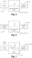
Figs. 6-7 are schematic views of pressure passages in the system ofFig. 1 for the discharge kidney ports, for the inlet kidney ports, and for the pressure regulated kidney ports of the kidney port plate ofFig. 3 , respectively; and -
Fig. 8 is a schematic axial end view of a portion of the system ofFig. 3 , showing a configuration with six kidney ports. - Reference will now be made to the drawings wherein like reference numerals identify similar structural features or aspects of the subject disclosure. For purposes of explanation and illustration, and not limitation, a partial view of an embodiment of a system in accordance with the disclosure is shown in
Fig. 1 and is designated generally byreference character 100. Other embodiments of systems in accordance with the disclosure, or aspects thereof, are provided inFigs. 2-8 , as will be described. The systems and methods described herein can be used to pressure balance over vane and under vane pressures of vanes in vane pumps, which can make possible the use of fracture tough materials for the vanes. - The
vane pump system 100 includes aliner 102 that has a bore extending therethrough that defines thecircumferential cam surface 104 of a pumping cavity. A rotation axis A is defined in an axial direction through the bore. Thecircumferential cam surface 104 includes two sets of functional pumping cam arcs to balance therotor 106 arc segment. There are two diametrically opposedinlet arc segments cam surface 104. Downstream of each (with respect to the flow of fluid from the inlets 101) is a respectivepump arc segment cam surface 104 circumferentially separating each of theinlet arc segments discharge arc segment 116, 118 of thecam surface 104 from one another. There are two diametrically opposedseal arc segments cam surface 104, circumferentially separating first set of pumping cam arcs 104, 112, 106 from the second set of pumping cam arcs 110, 114, 118. - The
cylindrical rotor 106 is mounted for rotational movement within the bore of theliner 102 about the rotation axis A. Therotor 106 has acentral body portion 120 which includes the plurality of circumferentially spaced apart radially extendingvane slots 122. Eachvane slot 122 supports a corresponding one of thevanes 124 mounted for radial movement therein relative to the rotation axis A as the outer (or over vane) tips 126 (labeled inFig. 4 ) of thevanes 124 slidingly engage and follow thecam surface 104. Each of thevanes 124 has a radially inner (or under vane) portion 128 (labeled inFig. 4 ), relative to the rotation axis A. The radially inner portion 128 of eachvane 124 is seated slidingly within itsrespective vane slot 122. - With reference now to
Fig. 2 , a pressure loadedport plate 130 is mounted to an axial end of theliner 102 opposite across the liner from akidney port plate 132, which is mounted to the other end of theliner 102. Theport plates liner 102. A shoulderedend cap 134 is mounted to the pressure loadedport plate 130 and to theliner 102, with the shoulderedend cap 134 radially outboard of theliner 102, and with the pressure loadedport plate 130 axially between the shoulderedend cap 134 and theliner 102. The inlets for the vane pump system pass through the shoulderedend cap 134 where indicated inFig. 2 andpressure plate port 130 to theinlet 101 positions indicated inFig. 1 . Adischarge end cap 136 is mounted to thekidney port plate 132, with thekidney port plate 132 axially between thedischarge end cap 136 and theliner 102. Thedischarge end plate 136 includes thedischarge outlets 103 of thepump system 100. - With reference now to
Fig. 3 , thekidney port plate 132 includes an diametrically opposed pair of overvane inlet ports inlet arc segment vanes 124. Thekidney port plate 132 includes a pair of diametrically opposed overvane discharge ports discharge arc segments 116, 118 for discharging pressurized fluid from the plurality ofvanes 124. Thekidney port plate 132 includeskidney ports vane inlet ports vane discharge ports kidney ports kidney ports vane slots 122 of therotor 102 for pressure balancing across the over vane and under vane ends 126, 128 of the plurality ofvanes 124. - A first pressure regulated or pressure regulated kidney port 148 is circumferentially adjacent to the first
inlet kidney port 146. A firstdischarge kidney port 150 is circumferentially adjacent to the first pressure regulated kidney port 148. A second pressure regulatedkidney port 152 is circumferentially adjacent to the firstdischarge kidney port 150. A secondinlet kidney port 154 is circumferentially adjacent to the second pressure regulatedkidney port 152. A third pressure regulated kidney port 156 is circumferentially adjacent to the secondinlet kidney port 154. A second discharge kidney port 158 is circumferentially adjacent to the third pressure regulated kidney port 156. A fourth pressure regulated kidney port 160 is circumferentially adjacent to the second discharge kidney port 158. The firstinlet kidney port 146 is circumferentially adjacent to the fourth pressure regulated kidney port 160. Optionally two of the kidney ports can be omitted, as discussed below with respect toFig. 8 . - With ongoing reference to
Fig. 3 , where circumferential references continue to be with respect to the rotation axis A, the first pressure regulated kidney port 148 is circumferentially aligned with the firstpump arc segment 112. The second pressure regulatedkidney port 152 is circumferentially aligned with theseal arc segment 162. The third pressure regulated kidney port 156 is circumferentially aligned with asecond pump arc 114. The fourth pressure regulated kidney port 160 is circumferentially aligned with a secondseal arc segment 164. The firstdischarge kidney port 150 is circumferentially aligned with thedischarge arc segment 116. The second discharge kidney port 158 is circumferentially aligned with the second discharge arc segment 118. The firstinlet kidney port 146 is circumferentially aligned with theinlet arc segment 108. The secondinlet kidney port 154 is circumferentially aligned with the secondinlet arc segment 110. - With reference now to
Figs. 5 and 6 , a firstfluid communication passage 166 is included configured so over vane pressure from thedischarge ports discharge kidney ports 150, 158 through at least one of therotor 102, the pressure loadedport plate 130, thekidney port plate 132, the shoulderedend cap 134, and/or thedischarge end cap 136. A secondfluid communication passage 168 is included configured so vane pump inlet pressure can be ported to the first and secondinlet kidney ports rotor 102, the pressure loadedport plate 130, thekidney port plate 132, the shoulderedend cap 134, and/or thedischarge end cap 136. - With reference now to
Fig. 7 , a pressure regulating valve (PRV) 170 is included in apressure balancing passage 172 configured so pressure from the over vane or undervane discharge kidney ports 148, 152, 156, 160. The PRV 170 is configured to reduce pressure from thedischarge inlets 101 ofFigs. 1-4 ) and discharge pressure of the rotor 102 (labeled inFigs. 1-4 ) to balance vane loading (indicated inFig. 4 ) in the first and second pump arc segments and in the first and secondseal arc segments 112, 114 (labeled inFig. 1 ). Thepressure balancing passage 172 is configured so pressure can be ported to the four pressure regulatedkidney ports 148, 152, 156, 160 through at least one of thedischarge end cap 136 and the shoulderedend cap 134. This pressure balancing accommodates more fracture tough materials for the vanes 124 (labeled inFigs. 1-4 ) than was feasible with traditional configurations. The plurality ofvanes 124 can be made of tool steel, for example. - With reference again to
Figs. 1-4 , the seal zones can be isolated with thekidney port plate 132. Thestraight vanes 124 can be ported inlet pressure, discharge pressure, or a regulated pressure of discharge - inlet pressure plus some margin to positively load the vanes into theliner 102. The PRV 170 ofFig. 7 creates pressure between inlet and discharge which is ported to the undervane cavities 122 to either match exactly the over vane net pressures or provide a slightly positive net pressure loading on the vane towards theliner 102. - With reference now to
Fig. 8 , a six kidney port configuration is disclosed, similar to the eight kidney port configuration ofFigs. 1-3 but with two fewer pressure regulated kidney ports. In this case, thekidney port plate 132 includes firstinlet kidney port 246 and a firstdischarge kidney port 248 circumferentially adjacent to the firstinlet kidney port 246. A first regulatedpressure kidney port 250 is circumferentially adjacent to the firstdischarge kidney port 248. A secondinlet kidney port 252 is circumferentially adjacent to the first regulatedpressure kidney port 250. A second discharge kidney port 254 is circumferentially adjacent to the second inletpressure kidney port 252. A second regulatedpressure kidney port 256 is circumferentially adjacent to the second discharge kidney port 254. The firstinlet kidney port 246 is circumferentially adjacent to the second regulatedpressure kidney port 256. Much as described above with respect toFig. 7 , a pressure regulating valve (PRV) 178 in apressure balancing passage 172 can be configured so pressure from discharge can be ported to the first and second regulatedpressure kidney ports PRV 178 is configured to reduce pressure from the discharge to an intermediate pressure between inlet pressure and discharge pressure of the rotor to balance vane loading in the first and second pump arc segments and in the first and second seal arc segments. Seal zones can be isolated with a sixkidney port plate 132. Straight vanes can be ported inlet pressure, discharge pressure, or a regulated pressure of discharge-inlet pressure plus some margin to positively load the vanes into the liner. Vane loading can be controlled with this configuration to allow more fracture tough materials such as tool steel to be utilized as the vane material. Pressure is ported to theundervane discharge kidneys 248, 254 via porting in one or multiple of the rotor, the port plate, or the end caps. Pressure is ported to the pressure regulatedkidney ports PRV 172 and then to the pressure regulatedkidney ports - System and methods as disclosed herein provide potential benefits including the following. The low loading achieved by the above system allows for the use of fracture tough vanes even with straight vane geometries. The methods and systems of the present disclosure, as described above and shown in the drawings, provide for pressure balancing over vane and under vane pressures of vanes in vane pumps, which can make possible use of fracture tough materials for the vanes. While the apparatus and methods of the subject disclosure have been shown and described with reference to preferred embodiments, those skilled in the art will readily appreciate that changes and/or modifications may be made thereto without departing from the scope of the subject disclosure.
Claims (15)
- A vane pump system comprising:
a kidney port plate configured to be engaged at an axial end of a rotor and of a liner, wherein the port plate is configured to be mounted stationary relative to the liner, wherein the kidney port plate includes:an over vane inlet port configured to be circumferentially aligned with an inlet arc segment of a circumferential cam surface of the liner for ingress of fluid to a plurality of vanes;an over vane discharge port configured to be circumferentially aligned with a discharge arc segment of the circumferential cam surface for discharging pressurized fluid from the plurality of vanes; andat least six kidney ports radially inward from the over vane inlet port and the over vane discharge port, wherein the kidney ports are circumferentially spaced apart from one another, and wherein the kidney ports are configured to be radially aligned with vane slots of the rotor for pressure balancing across over vane and under vane ends of the plurality of vanes. - The system as recited in Claim 1, wherein there are six kidney ports including:a first inlet kidney port;a first discharge kidney port circumferentially adjacent to the first inlet kidney port;a first regulated pressure kidney port circumferentially adjacent to the first discharge kidney port;a second inlet kidney port circumferentially adjacent to the first regulated pressure kidney port;a second discharge kidney port circumferentially adjacent to the second inlet pressure kidney port; anda second regulated pressure kidney port circumferentially adjacent to the second discharge kidney port, wherein the first inlet kidney port is circumferentially adjacent to the second regulated pressure kidney port,optionally comprising a pressure regulating valve (PRV) in a pressure balancing passage configured so pressure from discharge can be ported to the first and second regulated pressure kidney ports, wherein the PRV is configured to reduce pressure from the discharge to an intermediate pressure between inlet pressure and discharge pressure of the rotor to balance vane loading in the first and second pump arc segments and in the first and second seal arc segments.
- The system as recited in Claim 1, wherein there are eight kidney ports including:a first inlet kidney port;a first regulated pressure kidney port circumferentially adjacent to the first inlet kidney port;a first discharge kidney port circumferentially adjacent to the first regulated pressure kidney port;a second regulated pressure kidney port circumferentially adjacent to the first discharge kidney port;a second inlet kidney port circumferentially adjacent to the second regulated pressure kidney port;a third regulated pressure kidney port circumferentially adjacent to the second inlet kidney port;a second discharge kidney port circumferentially adjacent to the third regulated pressure kidney port; anda fourth regulated pressure kidney port circumferentially adjacent to the second discharge kidney port, wherein the first inlet kidney port is circumferentially adjacent to the fourth regulated pressure kidney port.
- The system as recited in claim 3, further comprising:the liner having a bore extending therethrough and defining the circumferential cam surface of a pumping cavity, with a rotation axis defined in an axial direction through the bore, the circumferential cam surface of the pumping cavity including the discharge arc segment, the inlet arc segment and a pump arc segment circumferentially separating the inlet arc segment and the discharge arc segment from one another; andthe rotor mounted for rotational movement within the bore of the liner about the rotation axis, the rotor having a central body portion which includes the vane slots, which are a plurality of circumferentially spaced apart radially extending vane slots formed in the rotor, each vane slot supporting a corresponding one of the plurality of vanes mounted for radial movement therein, each vane in the plurality of vanes having a radially outer tip surface adapted for slideably engaging the circumferential cam surface of the pumping cavity and a radially inner portion within each vane slot.
- The system as recited in claim 4, wherein the first regulated pressure kidney port is circumferentially aligned with the pump arc segment.
- The system as recited in claim 5, wherein the inlet arc segment is a first inlet arc segment, wherein the second regulated pressure kidney port is circumferentially aligned with a seal arc segment that is circumferentially between the discharge arc segment and a second inlet arc segment diametrically opposed to the first inlet arc segment.
- The system as recited in claim 6, wherein the pump arc segment is a first pump arc segment, wherein the third regulated pressure kidney port is circumferentially aligned with a second pump arc diametrically opposed to the first pump arc segment.
- The system as recited in claim 7, wherein the seal arc segment is a first seal arc segment, wherein the fourth regulated pressure kidney port is circumferentially aligned with a second seal arc segment that is diametrically opposed to the first seal arc segment, and/or
wherein the first discharge kidney port is circumferentially aligned with the discharge arc segment. - The system as recited in claim 8, wherein the discharge arc segment is a first discharge arc segment, wherein the second discharge kidney port is circumferentially aligned with a second discharge arc segment that is diametrically opposed to the first discharge arc segment, and/or
wherein the first inlet kidney port is circumferentially aligned with the inlet arc segment. - The system as recited in claim 9, wherein the inlet arc segment is a first inlet arc segment, wherein the second inlet kidney port is circumferentially aligned with a second inlet arc segment that is diametrically opposed to the first inlet arc segment.
- The system as recited in claim 10, further comprising a pressure loaded port plate mounted to an axial end of the liner opposite across the liner from the kidney port plate, wherein the pressure loaded port plate is fixed relative to the liner.
- The system as recited in claim 11, further comprising a shouldered end cap mounted to the pressure loaded port plate and to the liner, with the shouldered end cap radially outboard of the liner, and with the pressure loaded port plate axially between the shouldered end cap and the liner.
- The system as recited in claim 12, further comprising a discharge end cap mounted to the kidney port plate, with the kidney port plate axially between the discharge end cap and the liner.
- The system as recited in claim 13, wherein a first fluid communication passage is included configured so over vane pressure can be ported to the first and second discharge kidney ports through at least one of the rotor, the kidney port plate, the shouldered end cap, or the discharge end cap,
wherein optionally, a second fluid communication passage is included configured so vane pump inlet pressure can be ported to the first and second inlet kidney ports through at least one of the rotor, the kidney port plate, the shouldered end cap, or the discharge end cap. - The system as recited in claim 14, further comprising a pressure regulating valve (PRV) in a pressure balancing passage configured so pressure from discharge can be ported to the first, second, third, and fourth regulated pressure kidney ports, wherein the PRV is configured to reduce pressure from the discharge to an intermediate pressure between inlet pressure and discharge pressure of the rotor to balance vane loading in the first and second pump arc segments and in the first and second seal arc segments,
wherein optionally, the pressure balancing passage is configured so pressure can be ported to the first, second, third, and fourth regulated kidney ports through at least one of the discharge end cap and the shouldered end cap.
Applications Claiming Priority (1)
| Application Number | Priority Date | Filing Date | Title |
|---|---|---|---|
| US18/371,770 US20250101977A1 (en) | 2023-09-22 | 2023-09-22 | Kidney port configurations in port plates for balanced vanes |
Publications (1)
| Publication Number | Publication Date |
|---|---|
| EP4528077A1 true EP4528077A1 (en) | 2025-03-26 |
Family
ID=92894703
Family Applications (1)
| Application Number | Title | Priority Date | Filing Date |
|---|---|---|---|
| EP24201793.7A Withdrawn EP4528077A1 (en) | 2023-09-22 | 2024-09-20 | Vane pump with kidney port configurations in port plates for balanced vanes |
Country Status (2)
| Country | Link |
|---|---|
| US (1) | US20250101977A1 (en) |
| EP (1) | EP4528077A1 (en) |
Citations (3)
| Publication number | Priority date | Publication date | Assignee | Title |
|---|---|---|---|---|
| US2641195A (en) * | 1947-11-28 | 1953-06-09 | Oilgear Co | Sliding vave type hydrodynamic machine |
| US6634865B2 (en) | 2000-09-28 | 2003-10-21 | Goodrich Pump And Engine Control Systems, Inc. | Vane pump with undervane feed |
| US7637724B2 (en) | 2004-08-19 | 2009-12-29 | Hamilton Sundstrand Corporation | Variable displacement vane pump with pressure balanced vane |
Family Cites Families (4)
| Publication number | Priority date | Publication date | Assignee | Title |
|---|---|---|---|---|
| US2255784A (en) * | 1940-05-24 | 1941-09-16 | Manly Corp | Fluid pressure device |
| US2255785A (en) * | 1940-09-06 | 1941-09-16 | Manly Corp | Fluid pressure device |
| US4431389A (en) * | 1981-06-22 | 1984-02-14 | Vickers, Incorporated | Power transmission |
| JP7791778B2 (en) * | 2022-06-24 | 2025-12-24 | カヤバ株式会社 | vane pump |
-
2023
- 2023-09-22 US US18/371,770 patent/US20250101977A1/en not_active Abandoned
-
2024
- 2024-09-20 EP EP24201793.7A patent/EP4528077A1/en not_active Withdrawn
Patent Citations (3)
| Publication number | Priority date | Publication date | Assignee | Title |
|---|---|---|---|---|
| US2641195A (en) * | 1947-11-28 | 1953-06-09 | Oilgear Co | Sliding vave type hydrodynamic machine |
| US6634865B2 (en) | 2000-09-28 | 2003-10-21 | Goodrich Pump And Engine Control Systems, Inc. | Vane pump with undervane feed |
| US7637724B2 (en) | 2004-08-19 | 2009-12-29 | Hamilton Sundstrand Corporation | Variable displacement vane pump with pressure balanced vane |
Also Published As
| Publication number | Publication date |
|---|---|
| US20250101977A1 (en) | 2025-03-27 |
Similar Documents
| Publication | Publication Date | Title |
|---|---|---|
| US8011909B2 (en) | Balanced variable displacement vane pump with floating face seals and biased vane seals | |
| EP1320682B1 (en) | Vane pump | |
| AU2016269429B2 (en) | Multi-stage horizontal centrifugal pump for conveying a fluid and a method for repairing the same | |
| EP0582413B1 (en) | Hydraulic vane pump with enhanced axial pressure balance and flow characteristics | |
| EP1960632B1 (en) | End closure device for a turbomachine casing | |
| US9512929B2 (en) | Pressure balanced rotation spool valve | |
| WO2016090321A1 (en) | Systems and methods for rotor axial force balancing | |
| US10041491B2 (en) | Vane pump containing a back pressure introduction passage | |
| US6149409A (en) | Cartridge vane pump with dual side fluid feed and single side inlet | |
| EP0068354A1 (en) | A fluid pump or motor of the sliding vane type | |
| US20140271310A1 (en) | Clubhead Vane Pump With Balanced Vanes | |
| US4272227A (en) | Variable displacement balanced vane pump | |
| US4415319A (en) | Pump unit | |
| US20250101977A1 (en) | Kidney port configurations in port plates for balanced vanes | |
| EP2604790A2 (en) | Multi-discharge hydraulic vane pump | |
| US20140271296A1 (en) | No Corner Seal Rotary Vane Actuator | |
| US20120328463A1 (en) | Split discharge vane pump and fluid metering system therefor | |
| US20160032908A1 (en) | Distribution casing device for a hydraulic machine | |
| US20040131477A1 (en) | Vane pump wear sensor for predicted failure mode | |
| US20010016167A1 (en) | Static cam seal for variable displacement vane pump | |
| US6719543B2 (en) | Selectively adjustable fixed displacement vane pump | |
| EP3409945A1 (en) | Vane pump and method for determining profile inside cam ring constituting same | |
| JP3691761B2 (en) | Movable airfoil rotation device | |
| US5399077A (en) | Variable capacity vane pump | |
| US4529361A (en) | Vane pump having spokes with channel-shaped vanes |
Legal Events
| Date | Code | Title | Description |
|---|---|---|---|
| PUAI | Public reference made under article 153(3) epc to a published international application that has entered the european phase |
Free format text: ORIGINAL CODE: 0009012 |
|
| STAA | Information on the status of an ep patent application or granted ep patent |
Free format text: STATUS: THE APPLICATION HAS BEEN PUBLISHED |
|
| AK | Designated contracting states |
Kind code of ref document: A1 Designated state(s): AL AT BE BG CH CY CZ DE DK EE ES FI FR GB GR HR HU IE IS IT LI LT LU LV MC ME MK MT NL NO PL PT RO RS SE SI SK SM TR |
|
| STAA | Information on the status of an ep patent application or granted ep patent |
Free format text: STATUS: THE APPLICATION IS DEEMED TO BE WITHDRAWN |
|
| 18D | Application deemed to be withdrawn |
Effective date: 20250927 |