EP4528071A2 - Ablagerungsexklusivdruckverstärktes druckausgeglichenes einstellwerkzeug für liner-hänger - Google Patents
Ablagerungsexklusivdruckverstärktes druckausgeglichenes einstellwerkzeug für liner-hänger Download PDFInfo
- Publication number
- EP4528071A2 EP4528071A2 EP25156135.3A EP25156135A EP4528071A2 EP 4528071 A2 EP4528071 A2 EP 4528071A2 EP 25156135 A EP25156135 A EP 25156135A EP 4528071 A2 EP4528071 A2 EP 4528071A2
- Authority
- EP
- European Patent Office
- Prior art keywords
- tool
- volume
- pressure
- setting
- piston
- Prior art date
- Legal status (The legal status is an assumption and is not a legal conclusion. Google has not performed a legal analysis and makes no representation as to the accuracy of the status listed.)
- Granted
Links
Images








Classifications
-
- E—FIXED CONSTRUCTIONS
- E21—EARTH OR ROCK DRILLING; MINING
- E21B—EARTH OR ROCK DRILLING; OBTAINING OIL, GAS, WATER, SOLUBLE OR MELTABLE MATERIALS OR A SLURRY OF MINERALS FROM WELLS
- E21B23/00—Apparatus for displacing, setting, locking, releasing or removing tools, packers or the like in boreholes or wells
- E21B23/04—Apparatus for displacing, setting, locking, releasing or removing tools, packers or the like in boreholes or wells operated by fluid means, e.g. actuated by explosion
- E21B23/0416—Apparatus for displacing, setting, locking, releasing or removing tools, packers or the like in boreholes or wells operated by fluid means, e.g. actuated by explosion characterised by force amplification arrangements
-
- E—FIXED CONSTRUCTIONS
- E21—EARTH OR ROCK DRILLING; MINING
- E21B—EARTH OR ROCK DRILLING; OBTAINING OIL, GAS, WATER, SOLUBLE OR MELTABLE MATERIALS OR A SLURRY OF MINERALS FROM WELLS
- E21B23/00—Apparatus for displacing, setting, locking, releasing or removing tools, packers or the like in boreholes or wells
- E21B23/04—Apparatus for displacing, setting, locking, releasing or removing tools, packers or the like in boreholes or wells operated by fluid means, e.g. actuated by explosion
- E21B23/0413—Apparatus for displacing, setting, locking, releasing or removing tools, packers or the like in boreholes or wells operated by fluid means, e.g. actuated by explosion using means for blocking fluid flow, e.g. drop balls or darts
-
- E—FIXED CONSTRUCTIONS
- E21—EARTH OR ROCK DRILLING; MINING
- E21B—EARTH OR ROCK DRILLING; OBTAINING OIL, GAS, WATER, SOLUBLE OR MELTABLE MATERIALS OR A SLURRY OF MINERALS FROM WELLS
- E21B23/00—Apparatus for displacing, setting, locking, releasing or removing tools, packers or the like in boreholes or wells
- E21B23/04—Apparatus for displacing, setting, locking, releasing or removing tools, packers or the like in boreholes or wells operated by fluid means, e.g. actuated by explosion
-
- E—FIXED CONSTRUCTIONS
- E21—EARTH OR ROCK DRILLING; MINING
- E21B—EARTH OR ROCK DRILLING; OBTAINING OIL, GAS, WATER, SOLUBLE OR MELTABLE MATERIALS OR A SLURRY OF MINERALS FROM WELLS
- E21B23/00—Apparatus for displacing, setting, locking, releasing or removing tools, packers or the like in boreholes or wells
- E21B23/04—Apparatus for displacing, setting, locking, releasing or removing tools, packers or the like in boreholes or wells operated by fluid means, e.g. actuated by explosion
- E21B23/0411—Apparatus for displacing, setting, locking, releasing or removing tools, packers or the like in boreholes or wells operated by fluid means, e.g. actuated by explosion specially adapted for anchoring tools or the like to the borehole wall or to well tube
-
- E—FIXED CONSTRUCTIONS
- E21—EARTH OR ROCK DRILLING; MINING
- E21B—EARTH OR ROCK DRILLING; OBTAINING OIL, GAS, WATER, SOLUBLE OR MELTABLE MATERIALS OR A SLURRY OF MINERALS FROM WELLS
- E21B23/00—Apparatus for displacing, setting, locking, releasing or removing tools, packers or the like in boreholes or wells
- E21B23/04—Apparatus for displacing, setting, locking, releasing or removing tools, packers or the like in boreholes or wells operated by fluid means, e.g. actuated by explosion
- E21B23/0412—Apparatus for displacing, setting, locking, releasing or removing tools, packers or the like in boreholes or wells operated by fluid means, e.g. actuated by explosion characterised by pressure chambers, e.g. vacuum chambers
-
- E—FIXED CONSTRUCTIONS
- E21—EARTH OR ROCK DRILLING; MINING
- E21B—EARTH OR ROCK DRILLING; OBTAINING OIL, GAS, WATER, SOLUBLE OR MELTABLE MATERIALS OR A SLURRY OF MINERALS FROM WELLS
- E21B43/00—Methods or apparatus for obtaining oil, gas, water, soluble or meltable materials or a slurry of minerals from wells
- E21B43/02—Subsoil filtering
- E21B43/10—Setting of casings, screens, liners or the like in wells
Definitions
- a setting tool is used for deploying and setting a liner hanger system downhole.
- the drilling fluid in some downhole environments may be heavily laden drilling fluid of about 20 Ibf/gal (ppg) (2.4 kg/L or 2400 kg/m 3 ).
- a major weighting component in the drilling fluid is barite, which has the tendency to sag or deposit in low flow velocity and low-pressure gradient areas within the fluid column.
- barite When setting a liner hanger in this fluid environment, the deposited barite tends to accumulate in areas around a hydraulic setting cylinder used to set the slips of the liner hanger. This accumulation of barite tends to increase the actuation pressure required from the setting tool to move and set the slips of the liner hanger.
- a setting tool is used on tubing and is activated by applied tubing pressure behind a deployed plug to set a liner hanger in a borehole.
- the liner hanger has a hanger bore with at least one inlet port.
- the at least on inlet port is disposed in fluid communication with a hydraulic setting mechanism for the liner hanger.
- the setting tool comprises: a tool body, a bonnet, an actuator piston, a check valve, and an actuator seat.
- the piston may further comprise a cylindrical body disposed in the piston chamber, a first annular seal disposed on the cylindrical body and being configured to seal with the chamber seat, a second annular seal disposed on the cylindrical body and being sealed in sliding engagement with the piston chamber, and a biasing element disposed in the piston chamber and biasing the cylindrical body toward the chamber seat.
- the actuator piston may comprise a biasing element disposed in the second volume between a first shoulder of the tool bore and a second shoulder of the actuator piston, the biasing element being configured to resist movement of the first shoulder toward the second shoulder.
- the actuator piston may comprise a first temporary connection with the tool bore, the first temporary connection having a connected state configured to prevent movement of the actuator piston, the first temporary connection having an unconnected state in response to a predetermined force, the first temporary connection in the unconnected state being configured to allow movement of the actuator piston in response to the applied tubing pressure behind the deployed plug engaged in the actuator seat.
- the actuator piston may comprise seals disposed thereabout and sealed against the tool bore, wherein the stinger portion of the body may comprise a pack-off assembly having first and second annular seals sealed inside the hanger bore, the first and second annular seals isolating the at least one outlet port of the tool bore with the at least one inlet port of the hanger bore.
- the stinger portion may comprise a releasable connection inside the hanger bore, the releasable connection in an engaged condition having locking dogs engaged with the hanger bore, and the releasable connection in an unengaged condition having the locking dogs disengaged from the hanger bore.
- the actuator seat may comprise an expandable seat being configured to release the deployed plug from engagement therewith in response to a predetermined threshold of the applied tubing pressure.
- the method may further comprise setting the liner hanger in the borehole by actuating the hydraulic setting mechanism of the liner hanger using the intensified pressure, and releasing a releasable connection of the setting tool inside the liner hanger and retrieving the setting tool from the liner hanger set in the borehole.
- the method may further comprise relieving the intensified pressure of the actuation fluid above a predetermined threshold in the second volume to the first volume by opening a venting valve on the setting tool.
- Opening the venting valve on the setting tool may comprise applying the intensified pressure against a piston, and opening a venting port on the setting tool in response to movement of the piston.
- Drawing the actuation fluid from the first volume to the second volume may comprise allowing the first volume to decrease in response to the hydrostatic pressure, keeping the second volume set, and passing the actuation fluid from the decreasing first volume to the set second volume through a check valve on the setting tool.
- Intensifying the applied tubing pressure to the intensified pressure of the actuation fluid in the second volume of the actuator piston may comprise decreasing the second volume with the movement of the actuator piston and preventing the actuation fluid in the second volume from communication through the check valve to the first volume.
- Engaging the plug in the tubing on the actuator seat in the setting tool may comprise engaging the plug in the actuator seat associated with the actuator piston, unlocking the actuator seat in response to a predetermined threshold of the applied tubing pressure, and releasing the plug from the actuator seat in response to a predetermined threshold of the applied tubing pressure.
- Moving the actuator piston in the setting tool in response to the applied tubing pressure behind the engaged plug may comprise releasing a first temporary connection of the actuator piston in response to a predetermined force, and decreasing the second volume in response to the movement of the actuator piston.
- the method may further comprise releasing a second temporary connection of the actuator piston in response to the intensified pressure of the actuation fluid in the second volume exceeding a predetermined threshold; and permitting the second volume to increase in response to the released actuator piston.
- the method may further comprise releasing a releasable connection of the setting tool to the liner hanger; and retrieving the setting tool from the liner hanger set in the borehole.
- Communicating, in response to the movement of the actuator piston, the intensified pressure of the actuation fluid contained in the tool volume of the actuator piston from the at least one outlet port, to the at least one inlet port of the liner hanger, and to the hydraulic setting mechanism of the liner hanger may comprise: decreasing the tool volume of the actuator piston having the actuation fluid, and increasing pressure of the actuation fluid in the tool volume to the intensified pressure in response to the movement of the actuator piston from the tubing pressure applied to the actuator piston; and communicating the intensified pressure of the actuation fluid in the tool volume from the at least one outlet port of the setting tool, to the at least one inlet port of the liner hanger, and to the hydraulic setting mechanism of the liner hanger.
- the method may further comprise releasing a second temporary connection of the actuator piston in response to the intensified pressure of the actuation fluid in the tool volume exceeding a predetermined threshold; and permitting the tool volume to increase in response to the actuator piston being released.
- Keeping the actuation fluid contained in the setting tool separate from borehole fluid in the borehole and the tubing fluid in the tubing may comprise keeping the actuation fluid in a reserve volume of the setting tool separate from the borehole fluid, and keeping the actuation fluid in the tool volume of the actuator piston separate from the borehole fluid.
- the method may further comprise relieving the intensified pressure of the actuation fluid above a predetermined threshold in the tool volume to the reserve volume by opening a venting valve on the setting tool.
- Opening the venting port on the setting tool in response to movement of the venting valve piston may comprise releasing a temporary connection of the venting valve piston in response to the intensified pressure in the tool volume exceeding the predetermined threshold.
- Running the liner hanger into position in the borehole may comprise balancing pressure in the tool volume to hydrostatic pressure in the borehole by drawing the actuation fluid from the reserve volume to the tool volume.
- Drawing the actuation fluid from the reserve volume to the tool volume may comprise: allowing the reserve volume to decrease in response to the hydrostatic pressure; keeping the tool volume set; and passing the actuation fluid from the decreasing reserve volume to the set tool volume through a check valve on the setting tool.
- Communicating, in response to the movement of the actuator piston, the intensified pressure of the actuation fluid contained in the tool volume of the actuator piston may comprise: decreasing the tool volume with the movement of the actuator piston; and preventing the actuation fluid in the tool volume from communication through the check valve to the reserve volume.
- Preventing the actuation fluid in the tool volume from communication through the check valve to the reserve volume may comprise moving a check valve piston of the check valve from an opened condition to a closed condition in a piston chamber relative to a chamber seat in response to a pressure differential, the check valve piston in the closed condition being engaged with the chamber seat and preventing fluid communication from the tool volume to the reserve volume, the check valve piston in the opened condition being disengaged from the chamber seat and permitting fluid communication from the reserve volume to the tool volume.
- FIG. 1A illustrates a schematic view of a setting tool 50 deploying and setting a liner hanger 20 according to the present disclosure.
- a borehole 10 has casing 12 in which the liner hanger 20 is being deployed with the setting tool 50 to hang a liner 14.
- the setting tool 50 is connected to a running string 32 from the surface/rig deck/rig drawworks or the like.
- the running string 32 is run through a wellhead 30 and runs in the liner 14 and the liner hanger 20 through the casing 12.
- the setting tool 50 activates the liner hanger 20 by setting slips 22 and a packing element 24 so the liner 14 extends into the open borehole 10.
- the setting tool 50 of the present disclosure allows the liner hanger 20 to be run and set in downhole environments having a heavy, debris-laden drilling fluid, which would typically interfere with setting the liner hanger 20 as noted above.
- the setting tool (50) is released from the liner hanger system so additional operations can follow, such as cementing the liner 14 in the open borehole 10.
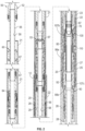
- Fig. 2 illustrates a cross-sectional view of the setting tool 50 according to the present disclosure for deploying and setting a liner hanger 20.
- the liner hanger 20 includes a mandrel 26 having a flow bore 28 therethrough.
- a hydraulic setting piston 25 (or other hydraulic setting mechanism) on the mandrel 26 can be hydraulically activated by fluid communication through a flow port 27 in the mandrel 26.
- the activated piston 25 pushes slips 22 on the mandrel 26 against cones 23 so that the slips 22 can engage inside the casing 12.
- the hanger 20 has a polished bore receptacle 21 attached to the upper end of the mandrel 26.
- the downhole end of the liner hanger 20 supports a liner (14).
- the setting tool 50 includes a body 56 having a flow bore 58 therethrough from an uphole end 52 to a downhole end 54.
- the uphole end 52 connects to a tubing string for running the setting tool 50 and liner hanger 20.
- the downhole end 54 can have additional tubing that includes a coupler for attaching additional component and that includes a pickup spacer (not shown) for removing components of the setting tool 50 from inside the hanger 20 during retrieval as discussed below.
- the flow bore 58 allows running fluid to pass through the setting tool 50 during run-in operations so that circulation can be provided as the liner (14) and hanger 20 are run through the borehole (10).
- a stinger portion of the tool body 56 uses a pack-off assembly 90 to seal inside the hanger bore 28 so at least one outlet port (not labelled in Fig. 2 ) on the tool body 56/pack-off assembly 90 is disposed in fluid communication with at least one inlet port 27 of the liner hanger's hydraulic setting piston 25.
- the locking mechanism 70 of the setting tool 50 allows for high circulation rates without wear or premature setting of the liner hanger 20.
- the setting tool 50 can withstand high-flow and circulation rates because the locking mechanism 70 prevents any unintentional movement of the actuator piston 84 until the system is unlocked and it is desired to set the system.
- the setting tool 50 can also withstand open-hole pack-off situations where circulation flow is suddenly stopped and wellbore pressure increases. The pressure increase without the locking mechanism 70 in place could cause the actuator piston 84 to actuate due to the differential piston surfaces that are on the actuator piston 84. With the locking mechanism 70 in place, however, the actuator piston 84 is held in place to internal pressures well above 10,000 psi (68,900 kPa). Pack-off pressure is not allowed to achieve such a magnitude because well formation damage would likely occur.
- the setting tool 50 of the present disclosure can mitigate issues encountered when setting the liner hanger 20 in such an environment.
- the setting tool 50 can overcome the resistance caused by deposits that accumulate in areas around the hydraulic setting piston 25 used to set the slips 22 of the hanger 20.
- This disclosed setting tool 50 provides the required actuation pressure from the setting tool 50 to move and set the slips 22 by intensifying the pressure applied by the tubing pressure behind the seated plug B.
- the inner workings of the setting tool's setting mechanism are kept free of the debris-laden drilling fluid to mitigate interference of the fluid with the actuation of the setting of the liner hanger 20 and to avoid fouling the setting tool 50 and the internal pressure volume 29 of the liner hanger 20.
- the disclosed setting tool 50 minimizes contact with the drilling fluid, which reduces operational risk for setting the liner hanger 20 and potential non-productive time (NPT).
- NPT potential non-productive time
- the liner hanger 20 will be exposed externally to the drilling fluid, but the internal actuation fluid and the means to deliver the pressurize fluid via the setting tool 50 are not contaminated or compromised by detrimental debris.
- Additional debris exclusion for the setting tool 50 is achieved by isolating the actuator piston 84, which is part of the slick stinger 80 of the setting tool 50.
- the slick stinger's piston 84 acts as a sealing sleeve that provides debris and pressure isolation during cementing operations during the liner hanger 50 installation.
- the slick stinger actuator 80 provides pressure control while transitioning to a packer setting position after cementing. However, prior to any of these functions, the slick stinger actuator 80 houses setting mechanisms required to actuate and provide isolated setting pressure to the hydraulic setting piston 25 of the liner hanger 20.
- the actuator piston 84 in the slick stinger actuator 80 is isolated from the drilling fluid by seals 85a-b. In this way, the actuator piston 84 can prevent the drilling fluid from being introduced into the clean fluid inside the tool volume 87.
- the clean setting fluid which is used as part of the fluid volume from the pack-off assembly 90, is fed from the balancing check valve 100.
- the setting fluid is completely isolated from external dirty fluids, and only clean fluids are introduced into the liner hanger setting port 27 and hydraulic chamber 29 of the hydraulic setting piston 25 during the setting operation.
- the disclosed setting tool 50 also excludes annular wellbore fluids by using the floating junk bonnet 60 and by isolating the tool volume 87 using the pack-off assembly 90. Additionally, to exclude debris, the intensifying actuator piston 84 uses clean fluid from the volumes 67, 87 of the bonnet 60 and the actuation mechanism. The actuator piston 84 does not introduce contaminated, dirty wellbore fluids into the hydraulic setting piston 25 of the liner hanger 20.
- the disclosed setting tool 50 is pressure-balancing because the setting tool 50 is always hydrostatically balanced via the balancing check valve 100 on the pack-off assembly 90. This ensures that only relative pressures above the hydrostatic pressure reference may be applied to set the liner hanger 20.
- the intensifying actuator piston 84 of the setting tool 50 can provide a power ratio of 3.6 to 1, multiplying the applied tubing pressure by almost 4 time to produce a setting pressure that provides a large setting force to push through debris-laden environment to set the slips 22 of the liner hanger 20.
- an applied tubing pressure from the surface of 2,600 psi (17,900 kPa) against the seated plug B in the actuator seat 82 relates to an applied setting pressure of about 10,000 psi (68,900 kPa) to the hydraulic setting piston 25 of the liner hanger 20.
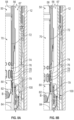
- Figs. 4A-4B illustrate cross-sectional views of detailed portions of the disclosed setting tool 50. These views are similar to those disclosed above with reference to Figs. 3A-3B .
- the actuator 80 is shown with the locking mechanism 70. Shown without a ball engaged in Fig. 4A , the seat 82 is held uphole by the locking mechanism 70. Shown with the ball engaged in Fig. 4B , the seat 82 is shifted downhole when the locking mechanism 70 is released.
- the piston 84 of the actuator 80 disposed in the bore 58 of the tool body 56 is not arranged to engage an uphole shear pin (88a; Figs. 3A-3B ) for a secondary pressure relief system of the tool volume 87 discussed in more detail below.
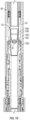
- Fig. 5 illustrates a process 200 for running in and setting the liner hanger 20 with the setting tool 50 of the present disclosure.
- the setting tool 50 is arranged (sealed and locked) in the liner hanger 20, the bonnet 60 has its volume filled with clean actuation fluid, etc.
- the liner hanger 20 is then run into position in the borehole using the setting tool 50 disposed on tubing.
- pressure in the setting tool's volume 87 is balanced to hydrostatic pressure in the borehole by drawing the actuation fluid from the reserve volume 67 of the bonnet 60 to the tool volume 87 of the tool 50 (Block 202).
- a setting ball B is dropped to the release mechanism 53 of the setting tool 50 (Block 204).
- the setting tool 50 is then unlocked using tubing pressure against the dropped ball B seated in a first seat of the release mechanism 53 (Block 206).
- Figs. 6A-6B and 7A-7C discussed below show details of this first stage of operation.
- the liner hanger 20 When successful, the liner hanger 20 is set in the casing 12 by actuating the hydraulic setting piston 25 of the liner hanger 20 using the intensified pressure (Block 224). When setting of the liner hanger 20 is successful in the end, then further stages of operation can follow in which cementing darts are dropped and a packer of the liner hanger system is set (Block 226). Once operations complete, a releasable connection 94 on the setting tool 50 is released from inside the liner hanger 20, and the setting tool 50 is retrieved from the liner hanger 20 set in the casing 12 (Block 228).
- Figs. 9A-9C show details related to this alternative stage. If setting operations fail, operation of the setting tool 50 can follow a retrieval plan to remove the tool 50 and liner hanger 20 (Block 240). Figs. 12-13 show some details of retrieval stages.
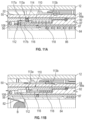
- Figs. 6A-6B and 7A-7C illustrate cross-sectionals views showing portions of the setting tool 50 and the liner hanger 20 in a first stages of setting. In these first stages, the liner hanger 20 is run to depth in the casing 12.
- the balancing check valve assembly 100 is a check valve that allows for pressure to balance between the clean reserve volume 62 of the junk bonnet 60 and the clean tool volume 87 for the activation piston 84 on the setting tool 50. Hydrostatic pressure builds as the setting tool 50 is run downhole, and the balancing check valve 100 allows fluid at the increasing pressure of the bonnet's volume 67 to enter into the tool's volume 87 for the activation piston 84. This ensures that there is a balance of pressure once the activation piston 84 is ready to be moved.
- the balancing check valve 100 has a piston chamber 102 and a piston 106.
- the piston chamber 102 in the form of a cylindrical chamber, is disposed in communication between the reserve and tool volumes 67, 87 and has a chamber seat 104 disposed therein.
- the piston 106 is in the form of a cylindrical body disposed in the piston chamber 102.
- the piston 106 is movable in the piston chamber 102 relative to the chamber seat 104 in response to a pressure differential.
- the movable piston 106 has an outer annular seal 107a that can selectively engage and seal with the chamber seat 104.
- An inner annular seal 107b on the piston 106 stays sealed to the tool body 56 and can include chevron seals as shown.
- the piston 106 in a closed position as shown in Fig. 6A has the seal 107a engaged with the chamber seat 104, which prevents fluid communication in the reverse direction from the tool volume 87 to the reserve volume 67.
- the piston 106 in an opened condition is disengaged from the chamber seat 104, which permits fluid communication from the reserve volume 67 to the tool volume 87.
- a biasing element 108 disposed in the piston chamber 102 biases the piston 106 toward the chamber seat 104 and acts against the pressure difference.
- Fig. 6B illustrates another detailed view of the balancing check valve assembly 100 for the disclosed setting tool 50. This view is similar to that disclosed above with reference to Fig. 6A .
- the actuator 80 is shown with the locking mechanism 70. Shown with the ball B engaged, the seat 82 is shifted downhole when the locking mechanism 70 is released.
- the piston 84 of the actuator 80 disposed in the bore 58 of the tool body 56 is not arranged to engage an uphole shear pin (88a; Figs. 3A-3B ) in an uphole direction for the secondary pressure relief system of the tool volume 87 discussed in more detail below
- the setting tool 50 is then unlocked once run to depth.
- a ball B is landed on the setting tool's release seat 55a of the release mechanism 53.
- Tubing pressure is increased to a predetermined pressure (e.g., 500 psi or 3,400 kPa) to shift a sleeve 55c, which unprops locking dogs 55d in the release mechanism 53.
- a predetermined pressure e.g. 500 psi or 3,400 kPa
- the setting tool's body 56 can be manipulated relative to other components of the system.
- the ball B is expelled from expandable release seat 55a to travel toward the tool's second seat (82) for setting the liner hanger (20).
- Figs. 8A-8B shows details of the second stage of operation.
- the ball B lands on the second expandable seat 82 of the slick stinger actuator 80.
- the seat 82 has pressure acting on both sides so the arrangement is pressure balanced and the shear pins 74 do not have a load on them until the ball B engages in the seat 82.
- Pressure applied against the landed ball B shears the actuator seat 82 free of the locking mechanism 70 so that the actuator 80 can be operated.
- the locking mechanism 70 prevents premature actuation of the actuator 80, which could be caused by any number of reasons during run-in. For example, the velocity of the fluid flow through the seat 82 could prematurely activate the actuator 80 if not locked in place.
- the locking mechanism 70 includes a sleeve 72 having the actuator seat 82.
- the sleeve 72 is held by shear pins 74 inside the tool body 56, and a locking collet 76 has collet fingers 77 held engaged against a ring 78 inside the tool body 56.
- a locking collet 76 has collet fingers 77 held engaged against a ring 78 inside the tool body 56.
- other configurations can be used to lock the seat 82 in place.
- the actuator seat 82 While running in the hole with the liner hanger 20/setting tool 50, the actuator seat 82 is locked into place by the locking mechanism 70 having the supported locking collet 76.
- the shear pins 74 prevent premature movement of the sleeve 72 in response to forces during run-in, such as any forces caused by fluid flow through the tool body 56.
- the actuator piston 84 may only be actuated after a closed pressure volume is pressurized to produce the required force to shear locking pins 74 and un-support the locking collet 76 so the seat 82 can engage (affix to) the piston 84.
- the sleeve 72 can shear the shear pin 74 once a predetermined force is reached.
- the sleeve 72 then shifts a short distance.
- the shifted sleeve 72 then shoulders against the actuator's piston 84 so that pressure applied against the seated ball B in the seat 82 can be applied to the actuator's piston 84.
- a lock ring 79 such as an expanding locking C-ring 79 on the sleeve 72, can lock in a locking groove of the piston 84 to lock them together. This locking prevents re-supporting the collet 76 and locking the sleeve 72 again.
- the back support on the collet fingers 77 is removed.
- the unsupported collet fingers 77 can allow shifting of the actuator piston 84 uphole (to the left in Fig. 8B ) should the upper shear pin 88a be sheared according to procedures disclosed below.
- the piston 116 is movable in the piston chamber 112 relative to the shearable pin 114 in response to a pressure differential.
- the piston 116 in a first condition is disengaged with shearable pin 114 and prevents fluid communication from the tool volume 87 to the port 113a.
- the piston 116 in a second condition is engaged with the port's shearable pin 113a, and excess pressure in the tool volume 87 shears the shear pin 114, permitting fluid communication from the tool volume 87 to the port 113a.
Landscapes
- Life Sciences & Earth Sciences (AREA)
- Engineering & Computer Science (AREA)
- Geology (AREA)
- Mining & Mineral Resources (AREA)
- Physics & Mathematics (AREA)
- Environmental & Geological Engineering (AREA)
- Fluid Mechanics (AREA)
- General Life Sciences & Earth Sciences (AREA)
- Geochemistry & Mineralogy (AREA)
- Earth Drilling (AREA)
- Fluid-Pressure Circuits (AREA)
Applications Claiming Priority (3)
| Application Number | Priority Date | Filing Date | Title |
|---|---|---|---|
| US17/386,177 US11773672B2 (en) | 2021-07-27 | 2021-07-27 | Debris exclusive-pressure intensified-pressure balanced setting tool for liner hanger |
| EP22747862.5A EP4377551B1 (de) | 2021-07-27 | 2022-06-29 | Ablagerungsexklusivdruckverstärktes druckausgeglichenes einstellwerkzeug für liner-hänger |
| PCT/US2022/035606 WO2023009272A1 (en) | 2021-07-27 | 2022-06-29 | Debris exclusive-pressure intensified-pressure balanced setting tool for liner hanger |
Related Parent Applications (2)
| Application Number | Title | Priority Date | Filing Date |
|---|---|---|---|
| EP22747862.5A Division EP4377551B1 (de) | 2021-07-27 | 2022-06-29 | Ablagerungsexklusivdruckverstärktes druckausgeglichenes einstellwerkzeug für liner-hänger |
| EP22747862.5A Division-Into EP4377551B1 (de) | 2021-07-27 | 2022-06-29 | Ablagerungsexklusivdruckverstärktes druckausgeglichenes einstellwerkzeug für liner-hänger |
Publications (3)
| Publication Number | Publication Date |
|---|---|
| EP4528071A2 true EP4528071A2 (de) | 2025-03-26 |
| EP4528071A3 EP4528071A3 (de) | 2025-05-28 |
| EP4528071B1 EP4528071B1 (de) | 2026-04-08 |
Family
ID=82703115
Family Applications (2)
| Application Number | Title | Priority Date | Filing Date |
|---|---|---|---|
| EP22747862.5A Active EP4377551B1 (de) | 2021-07-27 | 2022-06-29 | Ablagerungsexklusivdruckverstärktes druckausgeglichenes einstellwerkzeug für liner-hänger |
| EP25156135.3A Active EP4528071B1 (de) | 2021-07-27 | 2022-06-29 | Ablagerungsexklusivdruckverstärktes druckausgeglichenes einstellwerkzeug für liner-hänger |
Family Applications Before (1)
| Application Number | Title | Priority Date | Filing Date |
|---|---|---|---|
| EP22747862.5A Active EP4377551B1 (de) | 2021-07-27 | 2022-06-29 | Ablagerungsexklusivdruckverstärktes druckausgeglichenes einstellwerkzeug für liner-hänger |
Country Status (6)
| Country | Link |
|---|---|
| US (2) | US11773672B2 (de) |
| EP (2) | EP4377551B1 (de) |
| AU (1) | AU2022319607A1 (de) |
| CA (1) | CA3223924A1 (de) |
| MX (1) | MX2024001172A (de) |
| WO (1) | WO2023009272A1 (de) |
Families Citing this family (7)
| Publication number | Priority date | Publication date | Assignee | Title |
|---|---|---|---|---|
| CN119507840A (zh) * | 2023-08-22 | 2025-02-25 | 中国石油天然气集团有限公司 | 一种尾管悬挂器系统及相关方法 |
| US12674376B2 (en) | 2024-04-09 | 2026-07-07 | Weatherford Technology Holdings, Llc | Liner hanger with hydraulic actuator lock |
| US12492601B2 (en) * | 2024-04-26 | 2025-12-09 | National Oilwell Varco, L.P. | Anti-preset liner hanger systems |
| WO2026029838A1 (en) * | 2024-08-01 | 2026-02-05 | Weatherford Technology Holdings, Llc | Intensifying setting tool for packer |
| US12371961B1 (en) | 2024-08-01 | 2025-07-29 | Weatherford Technology Holdings, Llc | Intensifying setting tool for packer |
| US20260085588A1 (en) * | 2024-09-26 | 2026-03-26 | Weatherford Technology Holdings, Llc | Liner hanger for debris-laden environment |
| US20260185420A1 (en) * | 2024-12-31 | 2026-07-02 | Halliburton Energy Services, Inc. | Downhole tool including a movable element coupled to a deployment piston via a shear feature |
Family Cites Families (18)
| Publication number | Priority date | Publication date | Assignee | Title |
|---|---|---|---|---|
| US4583593A (en) * | 1985-02-20 | 1986-04-22 | Halliburton Company | Hydraulically activated liner setting device |
| GB8802700D0 (en) * | 1988-02-05 | 1988-03-02 | Solinst Canada Ltd | Groundwater sampling apparatus |
| US5038860A (en) | 1989-03-16 | 1991-08-13 | Baker Hughes Incorporated | Hydraulically actuated liner hanger |
| GB9600103D0 (en) | 1996-01-04 | 1996-03-06 | Nodeco Ltd | Improvements to offshore drilling apparatus |
| WO2004104370A1 (en) | 2003-05-20 | 2004-12-02 | Weatherford/Lamb, Inc. | Hydraulic setting tool for liner hanger |
| US8100188B2 (en) | 2007-10-24 | 2012-01-24 | Halliburton Energy Services, Inc. | Setting tool for expandable liner hanger and associated methods |
| US8807231B2 (en) | 2011-01-17 | 2014-08-19 | Weatherford/Lamb, Inc. | Debris barrier assembly |
| US8517115B2 (en) | 2011-01-26 | 2013-08-27 | Halliburton Energy Services, Inc. | Setting tool |
| BR112014008347B1 (pt) | 2011-10-07 | 2020-07-21 | Halliburton Energy Services, Inc. | ferramenta para acoplar liberavelmente uma primeira tubulação a uma segunda tubulação em um furo de poço e método |
| US9074438B2 (en) * | 2011-11-15 | 2015-07-07 | Schlumberger Technology Corporation | Hydrostatic pressure independent actuators and methods |
| AU2014205066B2 (en) | 2013-01-14 | 2016-10-20 | Weatherford Technology Holdings, Llc | Surge immune liner setting tool |
| US9428998B2 (en) | 2013-11-18 | 2016-08-30 | Weatherford Technology Holdings, Llc | Telemetry operated setting tool |
| CN108119107B (zh) | 2013-12-05 | 2020-05-19 | 哈利伯顿能源服务公司 | 衬管吊架设置工具及其使用方法 |
| CN106661927B (zh) | 2014-07-28 | 2019-12-27 | 哈里伯顿能源服务公司 | 接合输送的完井工具和操作 |
| US10907428B2 (en) | 2015-08-03 | 2021-02-02 | Weatherford Technology Holdings, Llc | Liner deployment assembly having full time debris barrier |
| EP3415711A1 (de) | 2017-06-13 | 2018-12-19 | Welltec A/S | Bohrloch-patch-einstellwerkzeug |
| EP3914805B1 (de) * | 2019-01-23 | 2024-08-14 | Saltel Industries | Expandierbares liner-hanger-system und verfahren |
| US11578560B2 (en) | 2019-10-17 | 2023-02-14 | Weatherford Technology Holdings Llc | Setting tool for a liner hanger |
-
2021
- 2021-07-27 US US17/386,177 patent/US11773672B2/en active Active
-
2022
- 2022-06-29 MX MX2024001172A patent/MX2024001172A/es unknown
- 2022-06-29 EP EP22747862.5A patent/EP4377551B1/de active Active
- 2022-06-29 WO PCT/US2022/035606 patent/WO2023009272A1/en not_active Ceased
- 2022-06-29 EP EP25156135.3A patent/EP4528071B1/de active Active
- 2022-06-29 CA CA3223924A patent/CA3223924A1/en active Pending
- 2022-06-29 AU AU2022319607A patent/AU2022319607A1/en active Pending
-
2023
- 2023-07-21 US US18/225,048 patent/US12297706B2/en active Active
Also Published As
| Publication number | Publication date |
|---|---|
| MX2024001172A (es) | 2024-02-27 |
| US12297706B2 (en) | 2025-05-13 |
| US20230033711A1 (en) | 2023-02-02 |
| US20230358111A1 (en) | 2023-11-09 |
| CA3223924A1 (en) | 2023-02-02 |
| WO2023009272A1 (en) | 2023-02-02 |
| EP4528071A3 (de) | 2025-05-28 |
| US11773672B2 (en) | 2023-10-03 |
| AU2022319607A1 (en) | 2024-01-18 |
| EP4377551A1 (de) | 2024-06-05 |
| EP4377551B1 (de) | 2025-04-16 |
| EP4528071B1 (de) | 2026-04-08 |
Similar Documents
| Publication | Publication Date | Title |
|---|---|---|
| EP4377551B1 (de) | Ablagerungsexklusivdruckverstärktes druckausgeglichenes einstellwerkzeug für liner-hänger | |
| US10280706B1 (en) | Hydraulic setting tool apparatus and method | |
| US5810082A (en) | Hydrostatically actuated packer | |
| US9845661B2 (en) | Exercising a well tool | |
| US9303477B2 (en) | Methods and apparatus for cementing wells | |
| EP0606981B1 (de) | Ventilvorrichtung im Bohrloch | |
| EP1712731B1 (de) | Liner Hängevorrichtung, Einbauwerkzeug und Verfahren | |
| AU4796893A (en) | Gravel packing system | |
| GB2405884A (en) | Hydraulic setting tool for packers | |
| US12110761B2 (en) | Hydrostatically insensitive testing and injection plug | |
| US4804044A (en) | Perforating gun firing tool and method of operation | |
| EP3827154B1 (de) | Überdruckzehenventil mit atmosphärischer kammer | |
| US20250389165A1 (en) | Downhole tool employing a pressure intensifier | |
| NO20240469A1 (en) | Liquid spring communication sub | |
| EP2647789A2 (de) | Verfahren und Vorrichtung zum Zementieren von Bohrlöchern | |
| US12371961B1 (en) | Intensifying setting tool for packer | |
| GB2230802A (en) | Well control apparatus | |
| CN119507840A (zh) | 一种尾管悬挂器系统及相关方法 | |
| AU2013205697B2 (en) | Failsafe hydrostatic vent | |
| BR112024001491B1 (pt) | Ferramenta de assentamento usada em tubulação | |
| BR122024012741A2 (pt) | Métodos para assentar um suspensor de liner em um poço | |
| BR122024012741B1 (pt) | Métodos para assentar um suspensor de liner em um poço | |
| RU2768861C1 (ru) | Компоновка спускового инструмента для спуска, якорения и герметизации подвески хвостовика | |
| US20250361790A1 (en) | Well tool actuation upon pressure decrease | |
| WO2026029838A1 (en) | Intensifying setting tool for packer |
Legal Events
| Date | Code | Title | Description |
|---|---|---|---|
| PUAI | Public reference made under article 153(3) epc to a published international application that has entered the european phase |
Free format text: ORIGINAL CODE: 0009012 |
|
| STAA | Information on the status of an ep patent application or granted ep patent |
Free format text: STATUS: THE APPLICATION HAS BEEN PUBLISHED |
|
| AC | Divisional application: reference to earlier application |
Ref document number: 4377551 Country of ref document: EP Kind code of ref document: P |
|
| AK | Designated contracting states |
Kind code of ref document: A2 Designated state(s): AL AT BE BG CH CY CZ DE DK EE ES FI FR GB GR HR HU IE IS IT LI LT LU LV MC MK MT NL NO PL PT RO RS SE SI SK SM TR |
|
| REG | Reference to a national code |
Ref country code: DE Ipc: E21B0023040000 Ref country code: DE Ref legal event code: R079 Ref document number: 602022034401 Country of ref document: DE Free format text: PREVIOUS MAIN CLASS: E21B0043100000 Ipc: E21B0023040000 |
|
| PUAL | Search report despatched |
Free format text: ORIGINAL CODE: 0009013 |
|
| AK | Designated contracting states |
Kind code of ref document: A3 Designated state(s): AL AT BE BG CH CY CZ DE DK EE ES FI FR GB GR HR HU IE IS IT LI LT LU LV MC MK MT NL NO PL PT RO RS SE SI SK SM TR |
|
| RIC1 | Information provided on ipc code assigned before grant |
Ipc: E21B 43/10 20060101ALI20250423BHEP Ipc: E21B 33/04 20060101ALI20250423BHEP Ipc: E21B 23/04 20060101AFI20250423BHEP |
|
| STAA | Information on the status of an ep patent application or granted ep patent |
Free format text: STATUS: REQUEST FOR EXAMINATION WAS MADE |
|
| 17P | Request for examination filed |
Effective date: 20251127 |
|
| GRAP | Despatch of communication of intention to grant a patent |
Free format text: ORIGINAL CODE: EPIDOSNIGR1 |
|
| STAA | Information on the status of an ep patent application or granted ep patent |
Free format text: STATUS: GRANT OF PATENT IS INTENDED |
|
| INTG | Intention to grant announced |
Effective date: 20260113 |
|
| GRAS | Grant fee paid |
Free format text: ORIGINAL CODE: EPIDOSNIGR3 |
|
| GRAA | (expected) grant |
Free format text: ORIGINAL CODE: 0009210 |
|
| STAA | Information on the status of an ep patent application or granted ep patent |
Free format text: STATUS: THE PATENT HAS BEEN GRANTED |
|
| AC | Divisional application: reference to earlier application |
Ref document number: 4377551 Country of ref document: EP Kind code of ref document: P |
|
| AK | Designated contracting states |
Kind code of ref document: B1 Designated state(s): AL AT BE BG CH CY CZ DE DK EE ES FI FR GB GR HR HU IE IS IT LI LT LU LV MC MK MT NL NO PL PT RO RS SE SI SK SM TR |
|
| REG | Reference to a national code |
Ref country code: CH Ref legal event code: F10 Free format text: ST27 STATUS EVENT CODE: U-0-0-F10-F00 (AS PROVIDED BY THE NATIONAL OFFICE) Effective date: 20260408 Ref country code: GB Ref legal event code: FG4D |
|
| REG | Reference to a national code |
Ref country code: DE Ref legal event code: R096 Ref document number: 602022034401 Country of ref document: DE |
|
| REG | Reference to a national code |
Ref country code: IE Ref legal event code: FG4D |
|
| PGFP | Annual fee paid to national office [announced via postgrant information from national office to epo] |
Ref country code: AT Payment date: 20260714 Year of fee payment: 5 |