EP4528066A1 - A building aperture cover with a handle comprising a user interaction sensor arrangement - Google Patents
A building aperture cover with a handle comprising a user interaction sensor arrangement Download PDFInfo
- Publication number
- EP4528066A1 EP4528066A1 EP23198252.1A EP23198252A EP4528066A1 EP 4528066 A1 EP4528066 A1 EP 4528066A1 EP 23198252 A EP23198252 A EP 23198252A EP 4528066 A1 EP4528066 A1 EP 4528066A1
- Authority
- EP
- European Patent Office
- Prior art keywords
- handle
- unit
- rotation axis
- user interaction
- covering
- Prior art date
- Legal status (The legal status is an assumption and is not a legal conclusion. Google has not performed a legal analysis and makes no representation as to the accuracy of the status listed.)
- Pending
Links
Images





Classifications
-
- E—FIXED CONSTRUCTIONS
- E06—DOORS, WINDOWS, SHUTTERS, OR ROLLER BLINDS IN GENERAL; LADDERS
- E06B—FIXED OR MOVABLE CLOSURES FOR OPENINGS IN BUILDINGS, VEHICLES, FENCES OR LIKE ENCLOSURES IN GENERAL, e.g. DOORS, WINDOWS, BLINDS, GATES
- E06B9/00—Screening or protective devices for wall or similar openings, with or without operating or securing mechanisms; Closures of similar construction
- E06B9/56—Operating, guiding or securing devices or arrangements for roll-type closures; Spring drums; Tape drums; Counterweighting arrangements therefor
- E06B9/68—Operating devices or mechanisms, e.g. with electric drive
-
- E—FIXED CONSTRUCTIONS
- E05—LOCKS; KEYS; WINDOW OR DOOR FITTINGS; SAFES
- E05B—LOCKS; ACCESSORIES THEREFOR; HANDCUFFS
- E05B1/00—Knobs or handles for wings; Knobs, handles, or press buttons for locks or latches on wings
- E05B1/003—Handles pivoted about an axis perpendicular to the wing
-
- E—FIXED CONSTRUCTIONS
- E06—DOORS, WINDOWS, SHUTTERS, OR ROLLER BLINDS IN GENERAL; LADDERS
- E06B—FIXED OR MOVABLE CLOSURES FOR OPENINGS IN BUILDINGS, VEHICLES, FENCES OR LIKE ENCLOSURES IN GENERAL, e.g. DOORS, WINDOWS, BLINDS, GATES
- E06B9/00—Screening or protective devices for wall or similar openings, with or without operating or securing mechanisms; Closures of similar construction
- E06B9/24—Screens or other constructions affording protection against light, especially against sunshine; Similar screens for privacy or appearance; Slat blinds
- E06B2009/2464—Screens or other constructions affording protection against light, especially against sunshine; Similar screens for privacy or appearance; Slat blinds featuring transparency control by applying voltage, e.g. LCD, electrochromic panels
-
- E—FIXED CONSTRUCTIONS
- E06—DOORS, WINDOWS, SHUTTERS, OR ROLLER BLINDS IN GENERAL; LADDERS
- E06B—FIXED OR MOVABLE CLOSURES FOR OPENINGS IN BUILDINGS, VEHICLES, FENCES OR LIKE ENCLOSURES IN GENERAL, e.g. DOORS, WINDOWS, BLINDS, GATES
- E06B9/00—Screening or protective devices for wall or similar openings, with or without operating or securing mechanisms; Closures of similar construction
- E06B9/56—Operating, guiding or securing devices or arrangements for roll-type closures; Spring drums; Tape drums; Counterweighting arrangements therefor
- E06B9/68—Operating devices or mechanisms, e.g. with electric drive
- E06B2009/6809—Control
- E06B2009/6818—Control using sensors
-
- E—FIXED CONSTRUCTIONS
- E06—DOORS, WINDOWS, SHUTTERS, OR ROLLER BLINDS IN GENERAL; LADDERS
- E06B—FIXED OR MOVABLE CLOSURES FOR OPENINGS IN BUILDINGS, VEHICLES, FENCES OR LIKE ENCLOSURES IN GENERAL, e.g. DOORS, WINDOWS, BLINDS, GATES
- E06B9/00—Screening or protective devices for wall or similar openings, with or without operating or securing mechanisms; Closures of similar construction
- E06B9/02—Shutters, movable grilles, or other safety closing devices, e.g. against burglary
- E06B9/08—Roll-type closures
- E06B9/11—Roller shutters
- E06B9/15—Roller shutters with closing members formed of slats or the like
-
- E—FIXED CONSTRUCTIONS
- E06—DOORS, WINDOWS, SHUTTERS, OR ROLLER BLINDS IN GENERAL; LADDERS
- E06B—FIXED OR MOVABLE CLOSURES FOR OPENINGS IN BUILDINGS, VEHICLES, FENCES OR LIKE ENCLOSURES IN GENERAL, e.g. DOORS, WINDOWS, BLINDS, GATES
- E06B9/00—Screening or protective devices for wall or similar openings, with or without operating or securing mechanisms; Closures of similar construction
- E06B9/24—Screens or other constructions affording protection against light, especially against sunshine; Similar screens for privacy or appearance; Slat blinds
- E06B9/40—Roller blinds
- E06B9/42—Parts or details of roller blinds, e.g. suspension devices, blind boxes
Definitions
- a building fenestration may be provided with a covering unit, such as a roller blind or roller shutter, comprising a covering part for covering a major surface of the glass unit.
- a covering unit such as a roller blind or roller shutter
- Different control solutions are known for such coverings.
- a user may mechanically pull an endless string (e.g., a wire loop) in order to operate the covering unit to provide more or less coverage of the glass unit.
- a person may interact with the covering part of the covering unit directly and manually to pull or push a covering part to increase or decrease the amount of sunlight entering through the glass unit.
- a handheld remote control may e.g. wind or unwind the covering part by rotating a roller/barrel. This rotation may be provided by means of an electric motor.
- a user may hence operate one or more push buttons on the handheld remote control, and the handheld remote control may transmit wireless control signals based on thereon in order to move control the covering part to increase or decrease the amount of sunlight entering through the glass unit.
- the above mentioned control solutions may, at least in some situations, however, be user-unfriendly.
- the present disclosure relates to a building fenestration, such as a window.
- the building fenestration comprises a fixation frame and a movable unit.
- the movable unit is connected to the fixation frame by means of a hinge arrangement so that the movable unit is configured to be moved relative to the fixation frame between a closed unit position and an open unit position.
- the movable unit comprises an insulated glass unit comprising an exterior major surface.
- the building fenestration moreover comprises a handle, wherein the handle is attached to a part of the movable unit.
- the handle comprises a gripping part configured to be grasped by human hand.
- the handle is configured to be operated by human hand so as to control the movable unit to move between the open unit position and the closed unit position.
- the building fenestration comprises an architectural covering unit comprising a covering part.
- the covering part is configured to be operated so as to provide a covering of the insulated glass unit.
- At least one electric, architectural cover driver is configured to control the covering part.
- the handle comprises a user interaction sensor arrangement comprising a user interaction part.
- the user interaction sensor arrangement is configured to detect user interactions provided by human hand at the a user interaction part.
- the user interactions comprises at least a first user interaction around a first rotation axis in a first rotation direction and a second user interaction around the first rotation axis in an opposite rotation direction, respectively.
- a control system is configured to control the electric architectural cover driver, and thereby the covering part, so as to increase or decrease the covering of the of the insulated glass unit dependent on the detected rotation direction.
- the first rotation axis extends with an angle that is less than 30° to the longitudinal direction of a bottom profile of the building fenestration.
- a covering unit of a building fenestration may be controlled by means of a wireless remote control that is a handheld, battery powered unit.
- a wireless remote control that is a handheld, battery powered unit.
- hand held remote controls may tend to disappear or be mislaid.
- This problem may be solved by the present disclosure, as the user interaction part is placed at the fenestration handle at the fenestration comprising the covering unit. Also, it may be intuitive to the user to look near the window for a covering unit control option. The handle is accessible and visible to the user, and hence the user may see the user interaction part and try operating it.
- guests or other persons that are not used to operate the covering unit may find the user interface provided/facilitated by the user interaction part, intuitive.
- the present disclosure may also provide a solution that may be aesthetically appealing and/or enable fewer, separated parts to be installed.
- first rotation axis with an orientation as defined above may increase the chance that the user will experience an intuitive user interface.
- first rotation axis extends with an angle that is less than 30° to the longitudinal direction of a bottom profile of the building fenestration, this may enable an intuitive control. It may even be more intuitive if the first rotation axis extends nearly or substantially parallel to the longitudinal direction of a bottom profile of the building fenestration.
- Said bottom profile may e.g. be or comprise a frame profile, such as a structural frame profile, of the movable unit.
- the longitudinal direction of the bottom profile may be substantially horizontal. This may be the case when the fenestration is installed.
- a handheld, wireless remote control may also be configured to operate the covering unit in response to user interactions at the hand held remote control. In that case, should the handheld, wireless remote control stop working or be mislaid, the user interaction sensor arrangement may be used.
- the covering of the insulating glass unit by means of the covering unit may be configured so as to reduce or prevent flow of sunlight through the covered part of the insulated glass unit.
- An increase in/of the covering of the insulating glass unit may be provided by controlling the covering part so as to reduce the amount of sunlight that may enter through the insulating glass unit.
- a decrease of the covering of the insulating glass unit may be provided by controlling the covering part so as to increase the amount of sunlight that may enter through the insulating glass unit.
- the covering part may be arranged external to the insulating glass unit. In other embodiments of the present disclosure, the covering part may be arranged inside, such as integrated in, the insulating glass unit.
- the first rotation axis may be arranged with an angle less than 30° such as less than 10° or less than 5° to the longitudinal direction of the bottom profile of the building fenestration.
- the longitudinal direction of the first rotation axis may be within ⁇ 30°, such as within ⁇ 15° or within ⁇ 5° to a plane defined by/comprising an exterior major surface of the insulated glass unit. This may provide an intuitive solution and/or an aesthetically pleasing solution.
- the longitudinal direction of the first rotation axis may be non-parallel to the plane defined by/comprising an exterior major surface of the insulating glass unit. In other embodiments hereof, the longitudinal direction of the first rotation axis may be parallel to the plane defined by an exterior major surface of the glass unit.
- the longitudinal direction of the first rotation axis may incline towards or away from a plane defined by an exterior major surface of the insulating glass unit.
- the gripping part of the handle may be configured to be movable relative to the movable unit between a locking position and an unlocking position so as to lock or unlock the movable unit relative to the fixation frame, such as wherein the locking position is configured to be substantially horizontal.
- the user interactions may comprise or consists of gestures provided by human and at the surface of the user interaction part.
- the user interactions may comprise or consists of a sliding rubbing movement over the outer surface of the user interaction part in the said rotation direction(s). This may e.g. enable an aesthetically appealing solution and/or help to reduce the number of moving parts.
- the user interactions may comprise or consists of moving, such as rotating, a user interaction part body, such as a turn knob, relative to the handle, in said rotation direction(s).
- a user interaction part body such as a turn knob
- the handle may here comprise the user interaction part body part and/or the user interaction part body part may be attached to the handle.
- the building aperture cover may comprise a locking system, wherein the locking system is configured to be arranged in a locked state and an unlocked state, respectively.
- the movable unit may be configured to be movable towards the open position from the closed position when the locking system is in the unlocked state.
- the movable unit may be configured to be in a locked unit state in the closed unit position by means of said locking system when the locking system is in the locked state.
- the handle such as the gripping part, may be configured to be operated by human hand so as to control in which of said states the locking system is arranged.
- the handle may in one or more embodiments be attached to a bottom frame profile of the movable unit or to a to top frame profile of the movable unit.
- the gripping part of the handle may be grabbed and pushed or pulled to either manually open or close the movable unit of the fenestration by human hand and/or to operate a locking part.
- This may e.g. provide a solution where the user interaction part is integrated with a handle that also serves for controlling the position of the movable unit and/or controlling a locking system of the fenestration.
- This may provide a space saving and/or intuitive solution, for example since more main control options related to the building fenestration (opening/closing and/or locking the window and covering/uncovering the window) are thereby located at the same part (the handle) of the window.
- Said control/manipulation of the locking system may e.g. comprise controlling the gripping part, such as moving the gripping part relative to the movable unit, e.g. by rotation of the gripping part around a rotation axis, so as to shift the state of the locking system between the locked state and an unlocked state.
- the movable unit In the locked unit state, the movable unit is directly or indirectly prevented by the locking system from moving towards the open position, this is the case when the movable unit is in the closed position and the locking system is in the locked state.
- the handle such as the gripping part
- the handle may be configured to be moved relative to the movable unit, such as by means of an actuator system and/or human hand, so as to control in which state the locking system is arranged.
- This movement may comprise a displacement and/or rotation of the gripping part relative to the movable unit. This may e.g. help to provide a user friendly solution, a mechanically simple solution and/or an intuitive solution for controlling the locking system.
- the gripping part is configured to be moved, such as by displacement and/or rotation, relative to the movable unit between a first gripping part position and a second gripping part position, respectively.
- the locking system may be configured to be arranged in the locked state when the gripping part is arranged in the first gripping part position.
- the locking system may be configured to be arranged in the unlocked state when the gripping part is arranged in the second gripping part position.
- This may e.g. help to provide a user friendly solution, a mechanically simple solution and/or an intuitive solution for controlling the locking system.
- the handle such as the gripping part, may in embodiments of the present disclosure be directly or indirectly coupled, such as mechanically coupled, to the locking system so as to be configured to switch the locking system between the locked state and the unlocked state in response to a movement of the gripping part relative to the movable unit.
- the at least one electric cover driver comprises an electric motor configured to provide movement of the covering part.
- the first rotation direction and the opposite rotation direction are oppositely directed.
- the opposite rotation direction may also be referred to as second rotation direction.
- the user interaction part comprises a turn knob which is configured to be rotated physically by human hand around the first rotation axis in the first rotation direction and in the second, opposite rotation direction, respectively.
- the user interaction part comprises a turn knob which is configured to be rotated physically by human hand relative to another part of the handle, such as relative to the gripping part, around the first rotation axis in the first rotation direction and in the second, opposite rotation direction, respectively.
- the user interaction part is physically rotatable in the desired rotation directions may e.g. help to improve user experience and/or provide a more intuitive control.
- the user interaction part may be spring-loaded. This may e.g. be provided for both, opposite rotation directions. Thereby, when a user releases the user interaction part, the user interaction part returns to an initial position, such as an equilibrium position, due to said spring loading. In some embodiments, this may automatically stop the electric cover driver. In other embodiments of the present disclosure, the electric cover driver may continue to move the covering part to e.g. a predefined covering position or to a fully retracted position after a user has released the turn knob.
- the handle such as the user interaction sensor arrangement
- the handle may comprise a touch sensor arrangement, such as a tubular touch sensor arrangement.
- the touch sensor arrangement may be configured to detect a movement direction of a hand gesture provided by human hand around the user interaction part, where the hand gesture indicates the first or second movement direction, respectively.
- the user interaction part may, in some embodiments, not be rotated/rotatable relative to the handle.
- the touch sensor may e.g. enable providing a mechanically simple and/or aesthetically pleasing, solution.
- the handle may comprise a rotation sensor.
- the rotation sensor may e.g. comprise a "fixed" touch sensor arrangement that does not need to be physically moved relative to the movable unit or another part of the handle in order to detect the user interaction (rotation directions).
- the user interaction part may be arranged at a free end of the handle.
- the user interaction part may constitute/provide a free end of the handle.
- the user interaction part and the handle may be placed between sides of the movable unit, and/or at the top or bottom of the movable unit.
- the first rotation axis may be defined by the physical structure of the handle.
- the handle comprises a main body part, such as the gripping part.
- This main body part may define a longitudinal direction of the handle.
- the first rotation axis may be parallel to the longitudinal direction of the handle.
- This may e.g. provide an improved user experience.
- the gripping part may be configured to be rotated relative to the movable unit around a handle rotation axis. This may e.g. be provided in order to lock or unlock the movable unit.
- the handle rotation axis may be different to the first rotation axis.
- the handle rotation axis may in some embodiments of the present disclosure be configured to be substantially perpendicular to a plane comprising a major outer surface of the insulating glass unit.
- the handle rotation axis may in some embodiments of the present disclosure be configured to be substantially parallel to a plane comprising a major outer surface of the insulating glass unit.
- the building fenestration covers a building aperture in an outer building wall or in a roof structure of the building.
- the building fenestration may comprise or be a roof window.
- the roof window may in some embodiments be configured to be installed in an inclining roof structure, such as a roof structure having a roof pitch angle above 17°, for example a roof pitch angle between 17° and 85°, such as between 25° and 65°.
- the planes defined by major surfaces of the insulating glass unit are extending with an angle that may be substantially similar to, or defined by, the roof pitch angle when the roof window is installed.
- the building fenestration may comprise or be a facade window, such as a window where the planes defined by major surfaces of the insulating glass unit are substantially vertical when the window is installed (and the movable unit is in a closed position).
- the covering part is configured to be moved along a major surface of the glass unit in a covering direction and a retraction direction, respectively.
- Said increase or decrease of the covering of the of the insulated glass unit may hence be configured to be provided/obtained by the control system controlling the electric architectural cover driver so as to shift the covering part in either the covering direction or the retraction direction dependent on said detected rotation direction.
- This may e.g. provide a solution that is easy to retrofit and/or access. It may additionally or alternatively provide a reliable solution and/or a solution where e.g. service is made more easy.
- the first rotation axis may be substantially perpendicular to the covering direction and the retraction direction.
- the longitudinal direction of the bottom profile may be substantially perpendicular to the covering direction and the retraction direction.
- the covering direction and the retraction direction may be substantially oppositely directed.
- the architectural covering unit may comprise or be a roller cover.
- the roller cover may comprise a roller shutter, such as an exterior roller shutter.
- the roller cover may comprise a roller blind, such as an exterior or interior roller blind.
- Roller covers provides solutions that have shown to be reliable sun coverings, and may be relatively space saving when in a retracted position. Roller covers may also enable more easy retrofitting of the covering solution.
- the covering part may be configured to be winded and un-winded on a roller by means of the electric cover driver, wherein the roller is configured to be rotated around a roller rotation axis.
- the angular difference between the longitudinal direction of the first rotation axis and the roller rotation axis may in embodiments of the present disclosure be less than 30° such as less than 10° or less than 5°.
- the first rotation axis and the roller rotation axis are substantially parallel.
- the covering part may comprise a film such as an electrically switchable film. This may e.g. provide an aesthetically pleasing covering solution, a space saving solution and/or the like.
- the film may be configured to roll or unroll dependent on an electric voltage and current applied to a coating, e.g. a coating on the glass unit.
- the covering part may comprise a switchable smart glass arrangement such as an electrically switchable smart glass arrangement. This may e.g. provide an aesthetically pleasing covering solution, a space saving solution and/or the like.
- the covering part may comprise or be a polymer dispersed liquid crystal (PDLC). This may be configured to change transparency in response to e.g. a controlled, applied electrical voltage.
- PDLC polymer dispersed liquid crystal
- the covering part may comprise or be a suspended particle device (SPD). This may be configured to change transparency in response to a controlled, applied electrical voltage.
- SPD suspended particle device
- the covering part may comprise or be a electrochromic device (EC)/(ECD).
- the covering part may comprise or be a micro blind.
- the covering part may comprise at least one of the following covering part solutions:
- the at least one electric, architectural cover driver may comprise electric circuitry configured to control/change the transparency of the switchable smart glass solution in response to command signals/control signals received.
- the user interaction part may be arranged in continuation of the gripping part.
- the first rotation axis and a longitudinal direction of the gripping part may be parallel, and/or the first rotation axis and the longitudinal axis of the gripping part may coincide.
- the movable unit is configured to be rotated around a unit rotation axis when moved between the closed unit position and open unit position.
- the angular difference between the longitudinal direction of the first rotation axis and the unit rotation axis may in some embodiments be less than 30° such as less than 10° or less than 5°.
- the first rotation axis and the unit rotation axis may be substantially parallel.
- the fenestration may be of the type where the movable unit is centre hung. In a centre hung solution, the movable unit may be configured to rotate around a (horizontal) unit rotation axis located between top and bottom of the fenestration and extending between sides of the fenestration. In some embodiments, the fenestration may be of the type where the movable unit is top hung. In a top hung solution, the movable unit may be configured to rotate around a (horizontal) unit rotation axis located at the top of the fenestration (when the fenestration is installed in a building as intended/designed for).
- the fenestration may be of the type where the movable unit is bottom hung.
- the movable unit may be configured to rotate around a (horizontal) unit rotation axis located at the bottom of the fenestration (when the fenestration is installed in a building as intended/designed for).
- the architectural covering unit may e.g. be arranged at the top of the building fenestration.
- the handle may comprise electronic circuitry for detecting the user interactions provided by human hand at the user interaction part. This may comprise one or more of:
- the handle may comprise an electric power storage comprising one or more batteries for storing electric power for powering the electric circuitry.
- a first plane may be defined by/comprise a major surface of the insulating glass unit.
- the first plane may extend perpendicular to a second plane where the second plane extends parallel to the longitudinal direction of a bottom profile of the building fenestration.
- the longitudinal direction of the first rotation axis may extend with an angle that is 30° or less, such as 10° or less, such as 5° or less, to at least one of the first plane and to the second plane. This may include parallel to one or both of the first and second plane.
- the longitudinal direction of the first rotation axis may extend parallel to at least one of the first plane and the second plane. In certain embodiments hereof, the longitudinal direction of the first rotation axis may be parallel to both the first plane and the second plane.
- the first rotation axis may extend with an angle to the first plane that is 30° or less, such as 10° or less, such as 5° or less, to the first plane.
- the first rotation axis may extend with an angle to the second plane that is 30° or less, such as 10° or less, such as 5° or less, to the second plane.
- the longitudinal direction of the first rotation axis may extend with an angle that is 30° or less, such as 10° or less, such as 5° or less, to both the first plane and to the second plane.
- the longitudinal direction of the first rotation axis may extend un-parallel to at least one of the first plane and the second plane. In certain embodiments hereof, longitudinal direction of the first rotation axis may be un-parallel to both the first plane and second plane.
- the present disclosure moreover relates to a method of operating a covering part at a building fenestration.
- the building fenestration comprises
- the longitudinal direction of the first rotation axis may extend substantially parallel to the longitudinal direction of a bottom profile of the building fenestration.
- the building fenestration may be a building fenestration according to any of claims 1-15 and/or a building fenestration according to one or more of the embodiments described above.
- the present disclosure moreover relates, in a third aspect, to a building fenestration, such as a window.
- the building fenestration comprises a fixation frame and a movable unit.
- the movable unit is connected to the fixation frame by means of a hinge arrangement so that the movable unit is configured to be moved relative to the fixation frame between a closed unit position and an open unit position.
- the movable unit comprises an insulated glass unit comprising an exterior major surface.
- the building fenestration moreover comprises a handle, wherein the handle is attached to a part of the movable unit.
- the handle comprises a gripping part configured to be grasped by human hand.
- the handle is configured to be operated by human hand so as to control the movable unit to move between the open unit position and the closed unit position.
- the building fenestration comprises an architectural covering unit comprising a covering part.
- the covering part is configured to be operated so as to provide a covering of the insulated glass unit.
- At least one electric, architectural cover driver is configured to control the covering part.
- the handle comprises a user interaction sensor arrangement comprising a user interaction part.
- the user interaction sensor arrangement is configured to detect user interactions provided by human hand at the a user interaction part.
- the user interactions comprises at least a first user interaction around a first rotation axis in a first rotation direction and a second user interaction around the first rotation axis in an opposite rotation direction, respectively.
- a control system is configured to control the electric architectural cover driver, and thereby the covering part, so as to increase or decrease the covering of the of the insulated glass unit dependent on the detected rotation direction.
- a first plane is defined by a major surface of the insulating glass unit, and the first plane may extend perpendicular to a second plane. The second plane extends parallel to the longitudinal direction of a bottom profile of the building fenestration.
- the longitudinal direction of the first rotation axis may extend with an angle that is 30° or less, such as 10° or less, such as 5° or less, to at least one of the first plane and the second plane. This may include parallel to one or both of the first and second plane.
- the longitudinal direction of the first rotation axis may extend parallel to at least one of the first plane and the second plane. In certain embodiments hereof, longitudinal direction of the first rotation axis may be parallel to both the first plane and the second plane.
- the first rotation axis may extend with an angle to the first plane that is 30° or less, such as 10° or less, such as 5° or less, to the first plane.
- the first rotation axis may extend with an angle to the second plane that is 30° or less, such as 10° or less, such as 5° or less, to the second plane.
- the longitudinal direction of the first rotation axis may extend with an angle that is 30° or less, such as 10° or less, such as 5° or less, to both the first plane and to the second plane.
- the longitudinal direction of the first rotation axis may extend un-parallel to at least one of the first plane and the second plane. In certain embodiments hereof, longitudinal direction of the first rotation axis may be un-parallel to both the first plane and second plane.
- the building fenestration may be a building fenestration according to any of claims 1-16 and/or a building fenestration according to one or more of the embodiments described above.
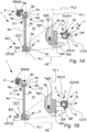
- Figs. 1A and 1B illustrates schematically a building fenestration, in this case a window, comprising a fixation frame 2, a movable unit 3, a covering unit 6, and a handle, 5.
- the window may e.g. be a roof window for installation in a building roof, or a facade window configured to installation vertically in an exterior building wall.
- the fixation frame 2 is configured to be arranged in a building aperture, and is configured to be fixated to a building structure such as a wall structure or a roof structure dependent on the fenestration type.
- the fixation frame 2 may comprise parallel elongated top and bottom profiles, and parallel elongated side profiles, respectively, which are mechanically connected so as to provide a rectangular frame opening.
- the movable unit 3 is attached to the fixation frame 2 by means of a hinge arrangement 14 (not illustrated in figs. 1A-1B , see e.g. figures described below according to various embodiments of the present disclosure).
- the hinge arrangement 13 provides that the movable unit 3 is configured to be moved relative to the fixation frame 2 between a closed unit position CPOS (the movable unit is in a closed position in figs 1A and 1B ) and an open unit position OPOS, around a unit rotation axis URAX (see e.g. various embodiments hereof described further below in relation to other figures of the present disclosure).
- the movable unit 3 comprises an insulated glass unit 4,
- the insulated glass unit 4 comprises an exterior major surface 4a that is configured to face the outside OUT of the building, and an interior major surface 4b that is configured to face the interior IN of the building.
- the insulated glass unit 4 comprises two or more glass sheets/panes 4gl1, 4gl2, and one or more insulating gaps 4g placed between the glass sheets. This or these insulating gap(s) may be gas filled or may be evacuated (in which case the insulated glass unit is a vacuum insulated glass unit) in order to provide thermal insulation.
- a major surface 4a, 4b, in the illustrated embodiment surface 4b, of the glass unit 4 defines/is comprised in a plane PL1.
- surfaces 4a, 4b are exterior surfaces in the sense that they face the outside environment, the outside OUT of the building and the inside IN of the building, respectively.
- the surfaces 4a, 4b may be coated or uncoated.
- the insulated glass unit 4 is designed to allow sunlight to pass through the or more glass sheets 4gl1, 4gl2 of the glass unit.
- sunlight in the visible spectrum such as a wave lengths from 380 to 700 nanometres may pass through the glass unit 4 panes from the outside OUT and into the building interior IN.
- light outside said visible spectrum may also pass through the glass unit 4 and into the building interior IN.
- the movable unit may 3 comprises a frame 3a comprising elongated, parallel top and bottom profiles, and elongated, parallel side profiles which together provides a rectangular frame with a frame opening between the profiles.
- the frame 3a supports the insulated glass unit 4, and the insulated glass unit 4 is fixed to the frame 3a of the movable unit, e.g. by means of adhesive and/or one or more mechanical fasteners.
- the frame 3a and/or 2 may be structural fenestration 1 components.
- the building fenestration comprises a Top TO and a bottom BO.
- the top TO is configured to be arranged further from the ground than the bottom BO.
- the top and bottom each extends in longitudinal directions between side parts of the fenestration 1, ad these longitudinal directions are parallel.
- the movable unit 3 may comprise an elongated top TO and an elongated bottom BO profile of the frame 3a, respectively, that are parallel and spaced apart.
- the building fenestration comprises an architectural covering unit 6 comprising a covering part 6a.
- the covering part 6a is configured to be operated so as to provide a covering of the insulating glass unit 4.
- the architectural covering unit 6 may comprise or be a roller cover.
- the roller cover 6 may be a roller shutter, such as an exterior roller shutter.
- the roller cover may be a roller blind, such as an exterior or interior roller blind.
- the architectural covering unit 6 may e.g. be arranged at the top of the building fenestration. In some embodiments, the architectural covering unit 6 may for example be attached directly or indirectly to the movable unit 3 and/or fixation frame 2.
- the covering part 6a of a roller blind may e.g. comprise a flexible sun-covering sheet (e.g. made from or comprising a fabric and/or a polymer sheet) configured to be winded and un-winded around a roller/barrel by means of an electric architectural cover driver 6b comprising an electric motor 6e.
- the motor 6e may be powered by mains and/or or a battery such as a rechargeable battery of the architectural covering unit 6 or fenestration 1.
- the covering part 6a of a roller shutter may e.g. comprise a plurality of slats, such as horizontal slats, that are configured to be winded and un-winded around a barrel/roller 6d by means of an electric architectural cover driver 6b comprising an electric motor 6e.
- the motor 6e may be powered by mains and/or or a battery such as a rechargeable battery of the architectural covering unit 6 or fenestration 1.
- the covering part 6b may be/provide a pleated curtain.
- the covering part 6a such as a sheet of a blind or a slat arrangement of a roller shutter, is configured to be moved along the major surface 4a of the glass unit 4, in a covering direction D1 and a retraction direction D2 respectively.
- An increase in the covering of the insulating glass unit is obtained by moving the covering part in the covering direction D1, and will result in a reduction of the amount of sunlight that may enter through the insulating glass unit.
- a decrease of the covering of the insulating glass unit is obtained by moving covering part in the retraction direction so as to increase the amount of sunlight that may enter through the insulating glass unit.
- the at least one electric architectural cover driver 6b may hence here comprise at least one electric cover actuator, such as an electric motor 6e, configured to provide movement of the covering part 6a based on received control signals COS.
- the covering part 6a may be configured to be winded and un-winded on the roller/barrel 6d (or in other ways displaced, dependent on the covering part type) by means of the electric cover driver motor 6e.
- the roller/barrel 6d is configured to be rotated around a roller rotation axis RRAX.
- the glass unit 4 gets increasingly more covered dependent on how much the covering part 6a is displaced, such as un-winded, in the covering direction D1.
- the glass unit 4 gets less covered dependent on how much the covering part 6a is displaced, such as un-winded, in the retraction direction D2.
- the displacement directions D2, D1 may reflect/be the result of opposite rotations directions of a driving part of the drive motor 6e.
- the covering part 6a of the architectural covering unit 6 may comprise a thin film/sheet.
- the film may be designed to be controllable to prevent or reduce sunlight entering the building through the insulated glass unit 4 and may also provide privacy.
- the glass unit 4 may in some embodiments comprise the film.
- An example of the film may comprise a thin film that is configured to roll, such as wind or unwind dependent on an electric charge/voltage, such as an electrostatic charge. A voltage and current may be applied to a coating or the like on a maj or surface of the glass unit which may induce the film to roll or unroll in the covering direction and uncovering direction, respectively.
- the architectural cover driver instead of the architectural cover driver being a motor, it may comprise electric circuitry configured to control the rolling and unrolling of the film.
- the covering part 6a may comprise or be an electrically switchable smart glazing arrangement such as comprising a smart glazing film. This may be configured to change transparency in response to e.g. an electrical voltage. Hence, the covering may be increased or decreased by controlling the smart glazing film.
- This control may be initiated by means of the user interaction part 7a dependent on the detected rotation direction RDIR1, RDIR2 provided by human hand, e.g. by means of a hand gesture or by physically rotating the user interaction part by hand.
- the electric architectural cover driver may thereby be controlled so as to e.g. control, such as change or switch, the transparency of the smart glazing film in response to user interactions RDIR1, RDIR2 provided by human hand.
- the covering part 6a may comprise or be a polymer dispersed liquid crystal (PDLC). This may be configured to change transparency in response to e.g. a controlled, applied electrical voltage.
- PDLC polymer dispersed liquid crystal
- the covering part 6a may comprise or be a suspended particle device (SPD). This may be configured to change transparency in response to a controlled, applied electrical voltage.
- SPD suspended particle device
- the covering part 6a may comprise or be a electrochromic device (EC)/(ECD).
- the covering part 6a may comprise or be a micro blind.
- the covering part may comprise at least one of the following covering part solutions:
- the glass unit 4 may in some embodiments comprise the electrically switchable smart glass arrangement.
- the at least one electric, architectural cover driver may comprise electric circuitry configured to control/change the transparency of the switchable smart glass solution in response to command signals COS received.
- the electric cover driver 6b may be configured to control the covering part 6a, such as e.g. a roller cover, a venetian blind, a smart glass arrangement or the like based on received control signals COS.
- the electric cover driver 6b may be configured to receive wired or wireless control signals COS.
- the handle 5 is attached to a part of the movable unit 3.
- the handle 5 is attached, e.g. directly or indirectly, to the frame 3a of the movable unit 3, in this case at the bottom BO of the building fenestration 1.
- the handle 5 may be attached to a bottom frame profile 3pb of the movable unit 3.
- the handle 5 may be attached, e.g. directly or indirectly, to a top frame profile 3pt of the movable unit 3
- the handle 5 comprises a gripping part 5a configured to be grasped by human hand.
- a user may by hand open or close the movable unit 3 by grasping the handle part 5a and thereby move the movable unit 3 relative to the fixation frame 2, e.g. by pushing or pulling the handle part 5a.
- the handle 5 is configured to be operated by human hand so as to control the movable unit 3 to move between an open unit position OPOS (see other figures described below) and the closed unit position (CPOS), respectively.
- the handle 5 comprises a user interaction sensor arrangement 7 for detecting user interaction applied to a user interaction part 7a.
- the user interaction sensor arrangement 7 comprises the user interaction part 7a.
- the user interaction sensor arrangement 7 is configured to detect user interactions RDIR1, RDIR2 provided by human hand, such as by one or more fingers of a human hand, at the user interaction part 7a. These user interactions comprise at least a first user interaction around a first rotation axis SRAX in a first rotation direction RDIR1 (see fig. 1A ) and a second user interaction around the first rotation axis SRAX in an opposite rotation direction RDIR2 (see fig. 1B ), respectively.
- a control system 7b, 6c is configured to control the electric architectural cover driver 6b so as to control the covering part 6a to either increase the covering of the insulating glass unit or decrease the covering of the insulating glass unit dependent on the detected rotation direction RDIR1, RDIR2.
- a sensor system 7b of the user interaction sensor arrangement 7 may be provided.
- the sensor system 7b comprises sensor circuitry and may be arranged at the handle, such as inside the handle.
- the sensor system 7b is configured to detect the applied, or indicated, rotation direction RDIR1, RDIR2 that is applied by a human hand to the user interaction part 7a.
- a transmission arrangement transmits command signals COS (wired or wirelessly) to a controller 6c of the electric architectural cover driver 6b.
- the sensor system may e.g. comprise a touch sensor or a mechanical sensor, such as an electromechanical sensor.
- the electric architectural cover driver 6b may e.g. be arranged at the covering unit 6, such as together with or implemented at or in a motor 6e, or another housing placed at another suitable location, e.g. at the covering unit 6.
- the controller 6c receives the control signals COS, and activates the electric architectural cover driver 6b to operate the covering device 6a in a desired direction that is indicated by the human hand applying or indicating (e.g. by a gesture or knob rotation) the rotation direction RDIR1, RDIR2 at the user interaction part 7a.
- each rotation direction RDIR1, RDIR2 is so to say assigned a movement directions D1, D2.
- the covering part 6a is configured to be controlled in the covering direction D1 in response to the sensor system 7b of the user interaction sensor arrangement 7 detecting a movement of (or at) the user interaction part 7a that represents/indicates a rotation direction RDIR1 around the rotation axis SRAX from the part DP of the user interaction part 7a that is distant to/faces away from the plane PL1 of the glass unit 4 and over a top portion TP of the user interaction part 7a or handle 5, towards the plane PL1.
- the covering part 6a is configured to be controlled in the un-covering direction/ retraction direction D2 in response to the sensor system 7b detecting a movement of (or at) the user interaction part 7a that represents/indicates a rotation direction RDIR2 around the rotation axis SRAX from the part DP of the user interaction part 7a that is distant to/faces away from the plane PL1 of the glass unit 4 and over a bottom portion BP of the user interaction part 7a or handle 5, towards the plane PL1.
- detecting the rotation direction RDIR2 may provide that the covering part 6a is controlled in the covering direction D1
- detecting the rotation direction RDIR1 may provide that the covering part 6a is controlled in the un-covering direction/ retraction direction D2.
- the bottom portion BP may face towards the bottom BO of the building fenestration 1 and/or towards the ground (when the fenestration is installed). Additionally or alternatively, the top part TP may as illustrated face towards the top TO of the building fenestration 1 and/or upwards in a direction away from the ground (when the fenestration is installed) .
- top TP and bottom BP portions are oppositely directed.
- the electric architectural cover driver 6b may stop the motor.
- the motor may additionally or alternatively be configured to stop automatically if the covering part 6a has reach an extremity state such as fully extended, such as un-winded, or fully retracted, such as winded.
- a predefined series of user interactions may be applied by a user at the part 7a, which may be detected, and a predefined scenario may thereby be implemented by the control system.
- a user interaction code such as two or more consecutive rotations RDIR1, RDIR2 in the same direction may initiate that the covering part is provided into a "full covering” state or a “full uncovering"/ "fully retracted” state.
- the “full covering” state may provide that the covering part 6a is controlled so that as much as possible of the glass unit surface 4a is covered by the covering part.
- the “full uncovering” state may provide that as much as possible of the glass unit surface 4a is uncovered by the covering part 6a.
- the covering of the glass unit 4 by the covering part 6a provides that a part of, or substantially all of, the glass unit is "covered” by the covering part in the sense that a reduced amount of sunlight, or no sunlight, can pass through the glass unit at the covering area due to the covering. If the covering part is e.g. a blind or shutter, the covering will gradually decrease or increase dependent on the movement direction of the covering part of the shutter or blind.
- the first rotation axis SRAX may be parallel to the longitudinal direction of a profile of the frame 2 and/or 3a to which the handle 5 is attached.
- the first rotation axis SRAX and the roller rotation axis RRAX may be substantially parallel.
- the longitudinal direction of the first rotation axis SRAX is parallel to an exterior major surface 4a, 4b of the glass unit 4, such as parallel to the plane PL1. It is understood that the first rotation axis SRAX may deviate a bit from being fully parallel to exterior major surface 4a, 4b of the glass unit 4, and still be considered to be parallel to it. In some embodiments, the longitudinal direction of first rotation axis SRAX may be within ⁇ 10°, such as within ⁇ 5° or within ⁇ 2° to an exterior major surface 4a, 4b of the insulated glass unit 4.
- the first rotation axis SRAX is horizontal (Horizontal plane HZ is indicated in figs. 1A and 1B ).
- a handheld remote control (not illustrated) may also be configured to operate the covering unit 6, 6a in response to user interactions at the hand held remote control.
- the first axis SRAX, and the handle rotation axis HRAX may extend in directions that are perpendicular to each other and crosses each other. In some embodiments, the first axis SRAX, and the handle rotation axis HRAX may intersect.
- the handle 5 comprises a main body part 5, 5a, such as the gripping part 5a.
- This main body part such as the gripping part 5a, defines a longitudinal direction LDH of the handle 5 or the gripping part 5a and may have a longitudinal axis.
- the first rotation axis SRAX may as illustrated be configured to be parallel to the general longitudinal direction LDH of the handle, such as of the gripping part. In some embodiments, the first rotation axis (SRAX) and the longitudinal axis of the gripping part 5a may coincide.
- the gripping part 5a may extend with a distance to the movable unit 4, so that the fingers of a human hand can be placed in/into the space 8 between the gripping part 5a and the movable unit 3 when grasping around the gripping part 5a.
- suitable electronic circuitry 22 for detecting user interactions provided by human hand at the user interaction part 7a may be integrated in or at the handle 5. This may comprise one or more of
- the type and/or number of components of the electronic circuitry may naturally be adapted according to various embodiments of the present disclosure.
- the handle 5 may in embodiments of the present disclosure comprise an electric power storage 21 such as comprising one or more batteries for storing electric power for powering the electric circuitry 22. This or these batteries may, or may not, be rechargeable.
- the battery/batteries 22 may in some embodiments be replaced, e.g. by removing the user interaction part or another end part of the handle 5.
- Fig. 4 illustrates schematically an embodiment of the present disclosure, wherein the first axis SRAX, and the handle rotation axis HRAX, are displaced and may be comprised in different, e.g., parallel, planes. See also fig. 7 . This may for example be the case when the movable unit 3 is in a closed position CPOS and/or the handle 5 is in a first gripping part position GP1 so that a locking system is configured to be arranged in a locked state.
- the gripping part 5a is configured to be moved HRAX, in this case by rotation around axis HRAX, relative to the movable unit 3 between a first gripping part position GP1 and a second gripping part position GP2, respectively.
- a locking system (see e.g. various embodiments hereof described further below, e.g. in relation to figs. 7 and 9-11 ), is configured to be arranged in a locked state LS when the gripping part 5a is arranged in the first gripping part position GP1.
- the locking system is configured to be arranged in the unlocked state US when the gripping part 5a is arranged in the second gripping part position GP2.
- Fig. 5 illustrates schematically and in perspective an embodiment of a handle 5 attached to the movable unit of a fenestration 1, according to embodiments of the present disclosure, where the handle comprises two of said user interaction parts 7a of a user interaction sensor arrangement 7.
- the user interaction parts 7a are placed/located at each side of the gripping part of the handle 5.
- the first rotation axis SRAX of the user interaction parts 7a are in the illustrated embodiment of fig. 5 coincident.
- the user interaction parts 7a may here be configured so as to control each their covering unit, e.g. a roller shutter and a roller blind, respectively, a roller shutter and a film, or the like.
- the first rotation axis SRAX of the user interaction parts 7a may be non-coincident, for example, e.g. displaced relative to each other and/or be arranged with an angle relative to each other.
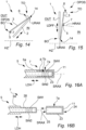
- the user interaction part 7a of the user interaction sensor arrangement 7 may comprises a turn knob which is configured to be rotated by human hand around the first rotation axis SRAX in the first switch rotation direction RDIR1 and the second, opposite switch rotation direction RDIR2, respectively. See also figs. 16A-16B .
- the rotation of the turn knob 7a may be relative to another part of the handle, such as the gripping part 5a, and is also relative to the movable unit 3.
- the user interaction part/parts 7a comprises such a turn knob, i.e. comprising a knob part 7a which is configured to be physically turned around the first rotation axis SRAX by hand.
- the user interaction part 7a comprising a turn knob may in embodiments of the present disclosure be directly or indirectly spring-loaded.
- This spring loading may e.g. be provided for both, opposite rotation directions.
- the user interaction part returns to an initial resting position, such as an equilibrium position, that may represent an inactivated state of the user interaction part 7b.
- Fig. 6 illustrates schematically and in perspective an embodiment of a handle 5 attached to the movable unit 3 of a fenestration 1, according to embodiments of the present disclosure, where a touch sensor arrangement 12 is configured to detect the user interactions RDIR1, RDIR2 at the user interaction part 7a of the user interaction sensor arrangement 7.
- the handle 5 comprises the sensor system 7b of the user interaction sensor arrangement 7, which comprises the touch sensor arrangement 12, such as a tubular touch sensor arrangement.
- the touch sensor arrangement 12 may be integrated in the handle 5.
- the touch sensor arrangement 12 is configured to detect a movement direction of a hand gesture provided by human hand around the user interaction part 7a, where the hand gesture indicates the first RDIR1 or second RDIR2 rotation direction, respectively.
- the user interactions RDIR1, RDIR2 may comprise or consists of gestures provided by human hand, such as fingers of a human hand at the surface of the user interaction part 7a.
- the user interactions RDIR1, RDIR2 may hence be registered without moving a part, such as a turn knob, relative to another part of the handle.
- the user interactions RDIR1, RDIR2 may comprise or consists of a sliding, rubbing, rotary movement over and relative to the outer surface of the user interaction part in the said rotation direction(s) RDIR1, RDIR2, around the first rotation axis SRAX.
- This is registered by means of the touch sensor arrangement and a processing unit (not illustrated) provides a command signal dependent on the registered user interaction in the rotation direction RDIR1, RDIR2.
- the touch sensor may e.g. be of the Resistance touch switch type, the capacitance touch switch type or the piezo touch switch type.
- the handle may comprise a rotation sensor.
- the rotation sensor may e.g. comprise a "fixed" touch sensor arrangement that does not need to be physically moved relative to the movable unit 3 and/or handle 5 (e.g. relative to the gripping part 5a) in order to detect the user interaction RDIR1, RDIR2, for example a tubular touch sensor arrangement.
- the rotation sensor may comprise a mechanical, rotatable switch/turn knob, such as a tubular switch/turn knob that is configured to be physically rotated by human hand to move relative to the movable unit 3 and/or handle 5 (e.g. relative to the gripping part 5a) in order to detect the user interaction RDIR1, RDIR2.
- the user interaction part may be unitary with the gripping part.
- the handle 5, in some embodiments of the present disclosure may comprise one or more visual and/or tactile indications indicating the presence of the user interaction part 7a and/or enable a user to distinguish between the gripping part 5a and the user interaction part 7a.
- a visual indication(s) may e.g. comprise a line, (e.g. dashed dotted or continuous), or the like, indicating the transition between the user interaction part 7a and the gripping part 5a.
- the visual indication may comprise a colour difference and/or colour nuance difference between the gripping part 5a and the user interaction part 7aand/or the like.
- the surface of the gripping part 5a and the surface of the user interaction part may comprise of be of different constitution and/or material.
- the handle 5 may be designed so that a user will experience/feel a tactile difference between the surface of the gripping part 5a and the surface of the user interaction part 7a to be interacted with by human hand.
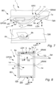
- Fig. 7 illustrates schematically an embodiment of the present disclosure, where the building fenestration 1 comprises a locking system.
- the locking system is configured to be arranged in a locked state and an unlocked state US (as in fig. 7 ), respectively,
- the movable unit 3 is configured to be movable towards the open position OPOS from a closed position CPOS (see e.g. previous figs.) when the locking system is in the unlocked state.
- the gripping part 5a is configured to be operated by human hand so as to control in which of said states the locking system is arranged.
- the handle 5 comprises the gripping part/grip part 5a configured to be grabbed and operated by human hand so that the handle is moved relative to the movable unit 3.
- the movable unit may comprise a frame comprising frame profiles such as structural frame profiles that shapes, such as frames a frame opening through which light can pass.
- the frame opening is covered by the insulating glass unit.
- This provides that a locking part 9a of the locking system is displaced between different states at the movable unit 3.
- the gripping part 5a is configured to be rotated around the rotation axis HRAX that is substantially perpendicular to a plane PL1 defined by/comprising a major surface (see example in previously described figures, such as e.g. fig. 1A and 1B and fig. 2 ) of the insulating glass unit 4.
- the handle 5 is mechanically connected to the locking part 5a, as the locking part 5a is integrated with the gripping part 5a as a unitary part.
- the locking part 5a may e.g. be or comprise one or more movable pawls configured to be operated by means of the handle arrangement.
- the locking system is thus configured to be arranged in different locking states by means of the handle.
- Fig. 7 illustrates the locking system in an unlocked state US.
- the locking system allows the movable unit 3 to open towards a substantially fully open position, as it does not engage with the engagement part 9b, such as a striker part, such as a striker plate, of the locking system.
- the engagement part 9b is attached to the fixation frame 2, such as attached to and/or integrated in the bottom profile 2pb (or in the top profile - not illustrated).
- the window is hence in an open state OS, and the handle is in grip position GP2 where the locking system is in an unlocked state.
- One or more mechanical stops (not illustrated) of the fenestration 1, for example provided by the hinge arrangement 14, a part of frame 2 and/or movable unit 3 and/or the like, may define/determine when the movable unit is fully open and hence cannot be opened more/further.
- the handle 5 may in embodiments of the present disclosure comprise a base part 5b that is attached, e.g. by means of one or more mechanical fasteners (not illustrated), to the movable unit 3, and the gripping part 5a may be mechanically attached to the base.
- the engagement part 9b is configured to cooperate with the locking part 9a so as to lock the movable unit 3 in a locking position/state relative to the fixation frame 2.
- the user interaction part 7a is placed at one of the sides of the handle 5, in this case the right side.
- the user interaction part may be laced at the left side, or one may be placed at each side of the handle.
- the user interaction part 7a may be placed between ends, or away from an end 11 of the handle.
- the longitudinal direction of the first rotation axis SRAX may be within ⁇ 30°, such as within ⁇ 10° or such as within ⁇ 5°, to the longitudinal direction LDH of the handle 5.
- the first rotation axis SRAX is not parallel with the longitudinal direction LDH of the handle.
- the longitudinal direction of the first rotation axis SRAX may be substantially parallel to the longitudinal direction LDH of the handle 5.
Landscapes
- Engineering & Computer Science (AREA)
- Structural Engineering (AREA)
- Architecture (AREA)
- Civil Engineering (AREA)
- Power-Operated Mechanisms For Wings (AREA)
Abstract
Description
- The present disclosure relates to a building fenestration Moreover, the present disclosure relates to a method of operating a covering part at a building fenestration.
- Various building fenestration types, such as e.g. windows, comprise an insulating glass unit that enable sunlight passing into the building when the building fenestration is installed to cover a building aperture in an outer wall or in a roof structure of the building. These fenestrations may comprise a handle that is configured to be operated by human hand in order to open or close a movable unit, such as a sash, of the window, to provide ventilation.
- However, in some situations, the inflow of sunlight through the insulating glass unit may be desired to be reduced, or privacy may be desired. Therefore, a building fenestration may be provided with a covering unit, such as a roller blind or roller shutter, comprising a covering part for covering a major surface of the glass unit. Different control solutions are known for such coverings. For example, a user may mechanically pull an endless string (e.g., a wire loop) in order to operate the covering unit to provide more or less coverage of the glass unit. In other solutions, a person may interact with the covering part of the covering unit directly and manually to pull or push a covering part to increase or decrease the amount of sunlight entering through the glass unit. In order to improve user friendliness, it is also known to provide a handheld remote control that may e.g. wind or unwind the covering part by rotating a roller/barrel. This rotation may be provided by means of an electric motor. A user may hence operate one or more push buttons on the handheld remote control, and the handheld remote control may transmit wireless control signals based on thereon in order to move control the covering part to increase or decrease the amount of sunlight entering through the glass unit. The above mentioned control solutions may, at least in some situations, however, be user-unfriendly.
- It may e.g. be an object of the present disclosure to provide a control solution for a building fenestration that may e.g. be intuitive to use by a human user. It may additionally or alternatively e.g. be an object of the present disclosure to provide a building aperture cover solution that is simple and user friendly.
- The present disclosure relates to a building fenestration, such as a window. The building fenestration comprises a fixation frame and a movable unit. The movable unit is connected to the fixation frame by means of a hinge arrangement so that the movable unit is configured to be moved relative to the fixation frame between a closed unit position and an open unit position. The movable unit comprises an insulated glass unit comprising an exterior major surface. The building fenestration moreover comprises a handle, wherein the handle is attached to a part of the movable unit. The handle comprises a gripping part configured to be grasped by human hand. The handle is configured to be operated by human hand so as to control the movable unit to move between the open unit position and the closed unit position. Moreover, the building fenestration comprises an architectural covering unit comprising a covering part. The covering part is configured to be operated so as to provide a covering of the insulated glass unit. At least one electric, architectural cover driver is configured to control the covering part. The handle comprises a user interaction sensor arrangement comprising a user interaction part. The user interaction sensor arrangement is configured to detect user interactions provided by human hand at the a user interaction part. The user interactions comprises at least a first user interaction around a first rotation axis in a first rotation direction and a second user interaction around the first rotation axis in an opposite rotation direction, respectively. A control system is configured to control the electric architectural cover driver, and thereby the covering part, so as to increase or decrease the covering of the of the insulated glass unit dependent on the detected rotation direction. The first rotation axis extends with an angle that is less than 30° to the longitudinal direction of a bottom profile of the building fenestration.
- For example, in some embodiments of the present disclosure, the first rotation axis may extend substantially parallel to the longitudinal direction of the bottom profile of the building fenestration. In other embodiments, the longitudinal direction of the first rotation axis be non- parallel to the longitudinal direction of the bottom profile of the building fenestration. solution according to the present disclosure may e.g. provide a covering/uncovering solution for a building fenestration that may be intuitive to use by a human user and may hence help to provide a solution where user operation mistakes are reduced.
- Often, a covering unit of a building fenestration may be controlled by means of a wireless remote control that is a handheld, battery powered unit. However, such hand held remote controls may tend to disappear or be mislaid. This problem may be solved by the present disclosure, as the user interaction part is placed at the fenestration handle at the fenestration comprising the covering unit. Also, it may be intuitive to the user to look near the window for a covering unit control option. The handle is accessible and visible to the user, and hence the user may see the user interaction part and try operating it.
- Additionally, e.g. guests or other persons that are not used to operate the covering unit may find the user interface provided/facilitated by the user interaction part, intuitive.
- The present disclosure may also provide a solution that may be aesthetically appealing and/or enable fewer, separated parts to be installed.
- Providing the first rotation axis with an orientation as defined above may increase the chance that the user will experience an intuitive user interface. When the first rotation axis extends with an angle that is less than 30° to the longitudinal direction of a bottom profile of the building fenestration, this may enable an intuitive control. It may even be more intuitive if the first rotation axis extends nearly or substantially parallel to the longitudinal direction of a bottom profile of the building fenestration.
- Said bottom profile may e.g. be or comprise a frame profile, such as a structural frame profile, of the movable unit.
- In one or more embodiments of the present disclosure, the longitudinal direction of the bottom profile may be substantially horizontal. This may be the case when the fenestration is installed.
- Moreover, a space saving, mechanically simple and/or cost efficient solution may be obtained.
- It is naturally understood that in addition to the user interaction sensor arrangement, a handheld, wireless remote control may also be configured to operate the covering unit in response to user interactions at the hand held remote control. In that case, should the handheld, wireless remote control stop working or be mislaid, the user interaction sensor arrangement may be used.
- It is generally understood that in embodiments of the present disclosure, the covering of the insulating glass unit by means of the covering unit may be configured so as to reduce or prevent flow of sunlight through the covered part of the insulated glass unit.
- An increase in/of the covering of the insulating glass unit may be provided by controlling the covering part so as to reduce the amount of sunlight that may enter through the insulating glass unit. A decrease of the covering of the insulating glass unit may be provided by controlling the covering part so as to increase the amount of sunlight that may enter through the insulating glass unit.
- It is understood that in embodiments of the present disclosure, the covering part may be arranged external to the insulating glass unit. In other embodiments of the present disclosure, the covering part may be arranged inside, such as integrated in, the insulating glass unit.
- In some embodiments of the present disclosure, the first rotation axis may be arranged with an angle less than 30° such as less than 10° or less than 5° to the longitudinal direction of the bottom profile of the building fenestration.
- In some embodiments of the present disclosure, the longitudinal direction of the first rotation axis may be within ±30°, such as within ±15° or within ±5° to a plane defined by/comprising an exterior major surface of the insulated glass unit. This may provide an intuitive solution and/or an aesthetically pleasing solution. In some embodiments hereof, the longitudinal direction of the first rotation axis may be non-parallel to the plane defined by/comprising an exterior major surface of the insulating glass unit. In other embodiments hereof, the longitudinal direction of the first rotation axis may be parallel to the plane defined by an exterior major surface of the glass unit.
- In some embodiments of the present disclosure, the longitudinal direction of the first rotation axis may incline towards or away from a plane defined by an exterior major surface of the insulating glass unit.
- In one or more embodiments of the present disclosure, the gripping part of the handle may be configured to be movable relative to the movable unit between a locking position and an unlocking position so as to lock or unlock the movable unit relative to the fixation frame, such as wherein the locking position is configured to be substantially horizontal.
- In one or more embodiments of the present disclosure, the user interactions may comprise or consists of gestures provided by human and at the surface of the user interaction part.
- In one or more embodiments of the present disclosure, the user interactions may comprise or consists of a sliding rubbing movement over the outer surface of the user interaction part in the said rotation direction(s). This may e.g. enable an aesthetically appealing solution and/or help to reduce the number of moving parts.
- In one or more embodiments of the present disclosure, the user interactions may comprise or consists of moving, such as rotating, a user interaction part body, such as a turn knob, relative to the handle, in said rotation direction(s). This may provide an intuitive and/or reliable solution. The handle may here comprise the user interaction part body part and/or the user interaction part body part may be attached to the handle.
- In one or more embodiments of the present disclosure, the building aperture cover may comprise a locking system, wherein the locking system is configured to be arranged in a locked state and an unlocked state, respectively. The movable unit may be configured to be movable towards the open position from the closed position when the locking system is in the unlocked state. The movable unit may be configured to be in a locked unit state in the closed unit position by means of said locking system when the locking system is in the locked state. In some embodiments, the handle, such as the gripping part, may be configured to be operated by human hand so as to control in which of said states the locking system is arranged.
- The handle may in one or more embodiments be attached to a bottom frame profile of the movable unit or to a to top frame profile of the movable unit.
- The gripping part of the handle may be grabbed and pushed or pulled to either manually open or close the movable unit of the fenestration by human hand and/or to operate a locking part. This may e.g. provide a solution where the user interaction part is integrated with a handle that also serves for controlling the position of the movable unit and/or controlling a locking system of the fenestration. This may provide a space saving and/or intuitive solution, for example since more main control options related to the building fenestration (opening/closing and/or locking the window and covering/uncovering the window) are thereby located at the same part (the handle) of the window.
- Said control/manipulation of the locking system may e.g. comprise controlling the gripping part, such as moving the gripping part relative to the movable unit, e.g. by rotation of the gripping part around a rotation axis, so as to shift the state of the locking system between the locked state and an unlocked state.
- In the locked unit state, the movable unit is directly or indirectly prevented by the locking system from moving towards the open position, this is the case when the movable unit is in the closed position and the locking system is in the locked state.
- In one or more embodiments if the present disclosure, the handle, such as the gripping part, may be configured to be moved relative to the movable unit, such as by means of an actuator system and/or human hand, so as to control in which state the locking system is arranged. This movement may comprise a displacement and/or rotation of the gripping part relative to the movable unit. This may e.g. help to provide a user friendly solution, a mechanically simple solution and/or an intuitive solution for controlling the locking system.
- In one or more embodiments if the present disclosure, the gripping part is configured to be moved, such as by displacement and/or rotation, relative to the movable unit between a first gripping part position and a second gripping part position, respectively. The locking system may be configured to be arranged in the locked state when the gripping part is arranged in the first gripping part position. The locking system may be configured to be arranged in the unlocked state when the gripping part is arranged in the second gripping part position.
- This may e.g. help to provide a user friendly solution, a mechanically simple solution and/or an intuitive solution for controlling the locking system.
- The handle, such as the gripping part, may in embodiments of the present disclosure be directly or indirectly coupled, such as mechanically coupled, to the locking system so as to be configured to switch the locking system between the locked state and the unlocked state in response to a movement of the gripping part relative to the movable unit.
- The handle, such as the gripping part, may in embodiments of the present disclosure be wirelessly coupled, such as magnetically or by means of a radio transmitter, to the locking system so as to be configured to switch the locking system between the locked state and the unlocked state in response to a movement of the gripping part relative to the movable unit.
- In one or more embodiments of the present disclosure, the gripping part may be configured to be moved, such as by displacement and/or rotation, relative to the movable unit between a first gripping part position and a second gripping part position by human hand, so that a disengagement of a lock between the fixation frame and the movable unit is provided.
- The first gripping part position may in some embodiments of the present disclosure be an outermost/end locking position of the gripping part. In some embodiments, substantially no further movement of the gripping part relative to the movable unit may be provided by human hand when in the first gripping part position, other than in the direction of/towards the second gripping part position so as to arrange the locking system in the unlocked state.
- In one or more embodiments of the present disclosure, the electric cover driver may be configured to move the covering part.
- In one or more embodiments of the present disclosure, the at least one electric cover driver comprises an electric motor configured to provide movement of the covering part.
- In one or more embodiments of the present disclosure, the handle may comprise one or more visual and/or tactile indications indicating the presence of the user interaction part and/or to enabling a user to distinguish between the gripping part and the user interaction part.
- The first rotation direction and the opposite rotation direction are oppositely directed. The opposite rotation direction may also be referred to as second rotation direction.
- In one or more embodiments of the present disclosure, the user interaction part comprises a turn knob which is configured to be rotated physically by human hand around the first rotation axis in the first rotation direction and in the second, opposite rotation direction, respectively.
- In one or more embodiments of the present disclosure, the user interaction part comprises a turn knob which is configured to be rotated physically by human hand relative to another part of the handle, such as relative to the gripping part, around the first rotation axis in the first rotation direction and in the second, opposite rotation direction, respectively.
- By providing that the user interaction part is physically rotatable in the desired rotation directions may e.g. help to improve user experience and/or provide a more intuitive control.
- In some embodiments, the user interaction part may comprise a mechanical, rotatable switch/turn knob, such as a tubular switch/turn knob.
- In some embodiments of the present disclosure, the user interaction part may be spring-loaded. This may e.g. be provided for both, opposite rotation directions. Thereby, when a user releases the user interaction part, the user interaction part returns to an initial position, such as an equilibrium position, due to said spring loading. In some embodiments, this may automatically stop the electric cover driver. In other embodiments of the present disclosure, the electric cover driver may continue to move the covering part to e.g. a predefined covering position or to a fully retracted position after a user has released the turn knob.
- In other embodiments of the present disclosure, the handle, such as the user interaction sensor arrangement, may comprise a touch sensor arrangement, such as a tubular touch sensor arrangement. The touch sensor arrangement may be configured to detect a movement direction of a hand gesture provided by human hand around the user interaction part, where the hand gesture indicates the first or second movement direction, respectively. Here, the user interaction part may, in some embodiments, not be rotated/rotatable relative to the handle. The touch sensor may e.g. enable providing a mechanically simple and/or aesthetically pleasing, solution.
- Hence it is understood that the handle may comprise a rotation sensor. The rotation sensor may e.g. comprise a "fixed" touch sensor arrangement that does not need to be physically moved relative to the movable unit or another part of the handle in order to detect the user interaction (rotation directions).
- In one or more embodiments of the present disclosure, the user interaction part may be arranged at a free end of the handle. For example, in one or more embodiments of the present disclosure, the user interaction part may constitute/provide a free end of the handle.
- In one or more embodiments of the present disclosure, the user interaction part and the handle may be placed between sides of the movable unit, and/or at the top or bottom of the movable unit.
- In one or more embodiments of the present disclosure, the first rotation axis may be defined by the physical structure of the handle.
- In one or more embodiments of the present disclosure, the handle comprises a main body part, such as the gripping part. This main body part may define a longitudinal direction of the handle. The first rotation axis may be parallel to the longitudinal direction of the handle.
- This may e.g. provide an improved user experience.
- In one or more embodiments of the present disclosure, the gripping part may be configured to be rotated relative to the movable unit around a handle rotation axis. This may e.g. be provided in order to lock or unlock the movable unit. The handle rotation axis may be different to the first rotation axis.
- The handle rotation axis may in some embodiments of the present disclosure be configured to be substantially perpendicular to a plane comprising a major outer surface of the insulating glass unit. Alternatively, the handle rotation axis may in some embodiments of the present disclosure be configured to be substantially parallel to a plane comprising a major outer surface of the insulating glass unit.
- In one or more embodiments of the present disclosure, the building fenestration covers a building aperture in an outer building wall or in a roof structure of the building.
- In one or more embodiments of the present disclosure, the building fenestration may comprise or be a window.
- In one or more embodiments of the present disclosure, the building fenestration may comprise or be a roof window. The roof window may in some embodiments be configured to be installed in an inclining roof structure, such as a roof structure having a roof pitch angle above 17°, for example a roof pitch angle between 17° and 85°, such as between 25° and 65°. In some embodiments, the planes defined by major surfaces of the insulating glass unit are extending with an angle that may be substantially similar to, or defined by, the roof pitch angle when the roof window is installed.
- In one or more embodiments of the present disclosure, the building fenestration may comprise or be a facade window, such as a window where the planes defined by major surfaces of the insulating glass unit are substantially vertical when the window is installed (and the movable unit is in a closed position).
- In one or more embodiments of the present disclosure, the covering part is configured to be moved along a major surface of the glass unit in a covering direction and a retraction direction, respectively. Said increase or decrease of the covering of the of the insulated glass unit may hence be configured to be provided/obtained by the control system controlling the electric architectural cover driver so as to shift the covering part in either the covering direction or the retraction direction dependent on said detected rotation direction.
- This may e.g. provide a solution that is easy to retrofit and/or access. It may additionally or alternatively provide a reliable solution and/or a solution where e.g. service is made more easy.
- In one or more embodiments of the present disclosure, the first rotation axis may be substantially perpendicular to the covering direction and the retraction direction.
- In one or more embodiments of the present disclosure, the longitudinal direction of the bottom profile may be substantially perpendicular to the covering direction and the retraction direction.
- The covering direction and the retraction direction may be substantially oppositely directed.
- In one or more embodiments of the present disclosure, the architectural covering unit may comprise or be a roller cover. In one or more embodiments of the present disclosure, the roller cover may comprise a roller shutter, such as an exterior roller shutter. In one or more embodiments of the present disclosure, the roller cover may comprise a roller blind, such as an exterior or interior roller blind.
- Roller covers provides solutions that have shown to be reliable sun coverings, and may be relatively space saving when in a retracted position. Roller covers may also enable more easy retrofitting of the covering solution.
- In one or more embodiments of the present disclosure, the covering part may be configured to be winded and un-winded on a roller by means of the electric cover driver, wherein the roller is configured to be rotated around a roller rotation axis. The angular difference between the longitudinal direction of the first rotation axis and the roller rotation axis may in embodiments of the present disclosure be less than 30° such as less than 10° or less than 5°. In some embodiments of the present disclosure, the first rotation axis and the roller rotation axis are substantially parallel.
- In other embodiments of the present disclosure, the covering part may comprise a film such as an electrically switchable film. This may e.g. provide an aesthetically pleasing covering solution, a space saving solution and/or the like.
- In some embodiments of the present disclosure, the film may be configured to roll or unroll dependent on an electric voltage and current applied to a coating, e.g. a coating on the glass unit.
- In other embodiments of the present disclosure, the covering part may comprise a switchable smart glass arrangement such as an electrically switchable smart glass arrangement. This may e.g. provide an aesthetically pleasing covering solution, a space saving solution and/or the like.
- In some embodiments of the present disclosure, the covering part may comprise or be a polymer dispersed liquid crystal (PDLC). This may be configured to change transparency in response to e.g. a controlled, applied electrical voltage.
- In some embodiments of the present disclosure, the covering part may comprise or be a suspended particle device (SPD). This may be configured to change transparency in response to a controlled, applied electrical voltage.
- In some embodiments of the present disclosure, the covering part may comprise or be a electrochromic device (EC)/(ECD).
- In some embodiments of the present disclosure (not illustrated), the covering part may comprise or be a micro blind.
- In some embodiments of the present disclosure (not illustrated), the covering part may comprise at least one of the following covering part solutions:
- a polymer dispersed liquid crystal (PDLC),
- a suspended particle device (SPD),
- An electrochromic device (EC)/(ECD),
- a micro blind
- In the case of the covering part comprises a switchable smart glass solution such as PDLC, SPD, ECD and micro blind solutions, the at least one electric, architectural cover driver may comprise electric circuitry configured to control/change the transparency of the switchable smart glass solution in response to command signals/control signals received.
- In one or more embodiments of the present disclosure, the user interaction part may be arranged in continuation of the gripping part. For example, in some embodiments, the first rotation axis and a longitudinal direction of the gripping part may be parallel, and/or the first rotation axis and the longitudinal axis of the gripping part may coincide.
- In one or more embodiments of the present disclosure, the movable unit is configured to be rotated around a unit rotation axis when moved between the closed unit position and open unit position. The angular difference between the longitudinal direction of the first rotation axis and the unit rotation axis may in some embodiments be less than 30° such as less than 10° or less than 5°. In some embodiments, the first rotation axis and the unit rotation axis may be substantially parallel.
- In some embodiments, the fenestration may be of the type where the movable unit is centre hung. In a centre hung solution, the movable unit may be configured to rotate around a (horizontal) unit rotation axis located between top and bottom of the fenestration and extending between sides of the fenestration. In some embodiments, the fenestration may be of the type where the movable unit is top hung. In a top hung solution, the movable unit may be configured to rotate around a (horizontal) unit rotation axis located at the top of the fenestration (when the fenestration is installed in a building as intended/designed for).
- In some embodiments, the fenestration may be of the type where the movable unit is bottom hung. In a bottom hung solution, the movable unit may be configured to rotate around a (horizontal) unit rotation axis located at the bottom of the fenestration (when the fenestration is installed in a building as intended/designed for).
- In some embodiments of the present disclosure, the architectural covering unit may e.g. be arranged at the top of the building fenestration.
- In some embodiments of the present disclosure, the handle may comprise electronic circuitry for detecting the user interactions provided by human hand at the user interaction part. This may comprise one or more of:
- One or more electric switches, such as rotary switches and/or one or more touch sensor arrangements,
- a computer processing unit, such as a microprocessor or the like for data processing,
- a data storage, such as for software code storage,
- a wired or wireless transmitter or transceiver for wireless command signals.
- In some embodiments of the present disclosure, the handle may comprise an electric power storage comprising one or more batteries for storing electric power for powering the electric circuitry.
- A first plane may be defined by/comprise a major surface of the insulating glass unit. In some embodiments of the present disclosure, the first plane may extend perpendicular to a second plane where the second plane extends parallel to the longitudinal direction of a bottom profile of the building fenestration.
- In one or more embodiments of the present disclosure, the longitudinal direction of the first rotation axis may extend with an angle that is 30° or less, such as 10° or less, such as 5° or less, to at least one of the first plane and to the second plane. This may include parallel to one or both of the first and second plane.
- In one or more embodiments of the present disclosure, the longitudinal direction of the first rotation axis may extend parallel to at least one of the first plane and the second plane. In certain embodiments hereof, the longitudinal direction of the first rotation axis may be parallel to both the first plane and the second plane.
- In some embodiments of the present disclosure, the first rotation axis may extend with an angle to the first plane that is 30° or less, such as 10° or less, such as 5° or less, to the first plane.
- In some embodiments of the present disclosure, the first rotation axis may extend with an angle to the second plane that is 30° or less, such as 10° or less, such as 5° or less, to the second plane.
- In some embodiments of the present disclosure, the longitudinal direction of the first rotation axis may extend with an angle that is 30° or less, such as 10° or less, such as 5° or less, to both the first plane and to the second plane.
- It is understood that in some embodiments of the present disclosure, the longitudinal direction of the first rotation axis may extend un-parallel to at least one of the first plane and the second plane. In certain embodiments hereof, longitudinal direction of the first rotation axis may be un-parallel to both the first plane and second plane.
- The present disclosure moreover relates to a method of operating a covering part at a building fenestration. The building fenestration comprises
- a fixation frame and a movable unit, wherein the movable unit is connected to the fixation frame by means of a hinge arrangement so that the movable unit is configured to be moved relative to the fixation frame between a closed unit position and an open unit position, wherein the movable unit comprises an insulated glass unit comprising an exterior major surface,
- a handle, wherein the handle is attached to a part of the movable unit, wherein the handle comprises a gripping part configured to be grasped by human hand, wherein the handle is configured to be operated by human hand so as to control the movable unit to move between the open unit position and the closed unit position,
- a covering unit comprising a covering part, wherein the covering part is configured to be operated so as to provide a covering of the insulated glass unit,
- at least one electric architectural cover driver configured to control the covering part.
- providing user interaction with the user interaction part by human hand by providing a rotational movement and/or gesture around a first rotation axis in a first rotation direction, and/or providing user interaction with the user interaction part by human hand by providing a rotational movement and/or gesture around the first rotation axis in a second rotation direction,
- wherein a control system controls the electric architectural cover driver so as to increase or decrease the covering of the of the insulated glass unit dependent on the detected rotation direction,
- wherein the longitudinal direction of the first rotation axis extends with an angle that is less than 30° to the longitudinal direction of a bottom profile of the building fenestration.
- In some embodiments of the method, the longitudinal direction of the first rotation axis may extend substantially parallel to the longitudinal direction of a bottom profile of the building fenestration.
- In some embodiments of the method, the building fenestration may be a building fenestration according to any of claims 1-15 and/or a building fenestration according to one or more of the embodiments described above.
- The present disclosure moreover relates, in a third aspect, to a building fenestration, such as a window. The building fenestration comprises a fixation frame and a movable unit. The movable unit is connected to the fixation frame by means of a hinge arrangement so that the movable unit is configured to be moved relative to the fixation frame between a closed unit position and an open unit position. The movable unit comprises an insulated glass unit comprising an exterior major surface. The building fenestration moreover comprises a handle, wherein the handle is attached to a part of the movable unit. The handle comprises a gripping part configured to be grasped by human hand. The handle is configured to be operated by human hand so as to control the movable unit to move between the open unit position and the closed unit position. Moreover, the building fenestration comprises an architectural covering unit comprising a covering part. The covering part is configured to be operated so as to provide a covering of the insulated glass unit. At least one electric, architectural cover driver is configured to control the covering part. The handle comprises a user interaction sensor arrangement comprising a user interaction part. The user interaction sensor arrangement is configured to detect user interactions provided by human hand at the a user interaction part. The user interactions comprises at least a first user interaction around a first rotation axis in a first rotation direction and a second user interaction around the first rotation axis in an opposite rotation direction, respectively. A control system is configured to control the electric architectural cover driver, and thereby the covering part, so as to increase or decrease the covering of the of the insulated glass unit dependent on the detected rotation direction.
In embodiments of the third aspect, a first plane is defined by a major surface of the insulating glass unit, and the first plane may extend perpendicular to a second plane. The second plane extends parallel to the longitudinal direction of a bottom profile of the building fenestration. - In some embodiments of the third aspect, the longitudinal direction of the first rotation axis may extend with an angle that is 30° or less, such as 10° or less, such as 5° or less, to at least one of the first plane and the second plane. This may include parallel to one or both of the first and second plane.
- In some embodiments of the third aspect, the longitudinal direction of the first rotation axis may extend parallel to at least one of the first plane and the second plane. In certain embodiments hereof, longitudinal direction of the first rotation axis may be parallel to both the first plane and the second plane.
- In some embodiments of the third aspect, the first rotation axis may extend with an angle to the first plane that is 30° or less, such as 10° or less, such as 5° or less, to the first plane.
- In some embodiments of the third aspect, the first rotation axis may extend with an angle to the second plane that is 30° or less, such as 10° or less, such as 5° or less, to the second plane.
- In some embodiments of the third aspect, the longitudinal direction of the first rotation axis may extend with an angle that is 30° or less, such as 10° or less, such as 5° or less, to both the first plane and to the second plane.
- It is understood that in some embodiments of the third aspect, the longitudinal direction of the first rotation axis may extend un-parallel to at least one of the first plane and the second plane. In certain embodiments hereof, longitudinal direction of the first rotation axis may be un-parallel to both the first plane and second plane.
- In some embodiments of the third aspect, the building fenestration may be a building fenestration according to any of claims 1-16 and/or a building fenestration according to one or more of the embodiments described above.
- Aspects of the present disclosure will be described in the following with reference to the figures in which:
- figs. 1A-1B
- : illustrates a building fenestration comprising a user interaction sensor arrangement for detecting user interaction applied to a user interaction part of a handle, according to embodiments of the present disclosure,
- figs. 2 and 3
- : illustrates a building fenestration comprising a handle with a user interaction part arranged at or providing a free end of a handle, according to various embodiments of the present disclosure,
- fig. 4
- : illustrates, a building fenestration comprising a handle having a gripping part that is rotated, according to embodiments of the present disclosure,
- fig. 5
- : illustrates, a building fenestration comprising a handle comprising two user interaction parts arranged at opposite free ends of a handle, according to embodiments of the present disclosure,
- fig. 6
- : illustrates, a building fenestration comprising a handle comprising a touch sensor configured to detect user interactions at a user interaction part, according to embodiments of the present disclosure,
- fig. 7
- : illustrates a building fenestration comprising a rotatable handle and a locking system, according to embodiments of the present disclosure,
- fig. 8
- : illustrates, a building fenestration comprising a handle arranged at a top part of the building fenestration, according to embodiments of the present disclosure,
- figs. 9-11
- : illustrates a building fenestration being a roof window and comprising a locking system, according to embodiments of the present disclosure,
- fig. 12
- : illustrates a building fenestration comprising a roller cover, according to embodiments of the present disclosure,
- figs. 13-15
- : illustrates various embodiments of a building fenestration, according to embodiments of the present disclosure,
- fig. 16A-16B
- : illustrates a handle comprising a rotatable user interaction part body, according to embodiments of the present disclosure, and
- fig. 17
- : illustrates a rotation axis where the rotation axis is parallel to the longitudinal direction of a bottom profile, according to embodiments of the present disclosure, and
- figs. 18-19
- : illustrates a rotation axis, where the rotation axis is arranged with an angle that is non-parallel with the longitudinal direction of a bottom profile, according to various embodiments of the present disclosure.
-
Figs. 1A and 1B illustrates schematically a building fenestration, in this case a window, comprising afixation frame 2, amovable unit 3, acovering unit 6, and a handle, 5. The window may e.g. be a roof window for installation in a building roof, or a facade window configured to installation vertically in an exterior building wall. - The
fixation frame 2 is configured to be arranged in a building aperture, and is configured to be fixated to a building structure such as a wall structure or a roof structure dependent on the fenestration type. Thefixation frame 2 may comprise parallel elongated top and bottom profiles, and parallel elongated side profiles, respectively, which are mechanically connected so as to provide a rectangular frame opening. - The
movable unit 3 is attached to thefixation frame 2 by means of a hinge arrangement 14 (not illustrated infigs. 1A-1B , see e.g. figures described below according to various embodiments of the present disclosure). - The
hinge arrangement 13 provides that themovable unit 3 is configured to be moved relative to thefixation frame 2 between a closed unit position CPOS (the movable unit is in a closed position infigs 1A and 1B ) and an open unit position OPOS, around a unit rotation axis URAX (see e.g. various embodiments hereof described further below in relation to other figures of the present disclosure). - The
movable unit 3 comprises aninsulated glass unit 4, The insulatedglass unit 4 comprises an exteriormajor surface 4a that is configured to face the outside OUT of the building, and an interiormajor surface 4b that is configured to face the interior IN of the building. - The
insulated glass unit 4 comprises two or more glass sheets/panes 4gl1, 4gl2, and one or moreinsulating gaps 4g placed between the glass sheets. This or these insulating gap(s) may be gas filled or may be evacuated (in which case the insulated glass unit is a vacuum insulated glass unit) in order to provide thermal insulation. - A
major surface embodiment surface 4b, of theglass unit 4 defines/is comprised in a plane PL1. - It is understood that
surfaces surfaces - The
insulated glass unit 4 is designed to allow sunlight to pass through the or more glass sheets 4gl1, 4gl2 of the glass unit. For example, sunlight in the visible spectrum, such as a wave lengths from 380 to 700 nanometres may pass through theglass unit 4 panes from the outside OUT and into the building interior IN. In some embodiments, light outside said visible spectrum may also pass through theglass unit 4 and into the building interior IN. - The movable unit may 3 comprises a
frame 3a comprising elongated, parallel top and bottom profiles, and elongated, parallel side profiles which together provides a rectangular frame with a frame opening between the profiles. Theframe 3a supports the insulatedglass unit 4, and theinsulated glass unit 4 is fixed to theframe 3a of the movable unit, e.g. by means of adhesive and/or one or more mechanical fasteners. - The
frame 3a and/or 2 may bestructural fenestration 1 components. - The building fenestration comprises a Top TO and a bottom BO. When the building fenestration is installed in a building, the top TO is configured to be arranged further from the ground than the bottom BO. The top and bottom each extends in longitudinal directions between side parts of the
fenestration 1, ad these longitudinal directions are parallel. Themovable unit 3 may comprise an elongated top TO and an elongated bottom BO profile of theframe 3a, respectively, that are parallel and spaced apart. - The building fenestration comprises an
architectural covering unit 6 comprising acovering part 6a. The coveringpart 6a is configured to be operated so as to provide a covering of the insulatingglass unit 4. - In some embodiments of the present disclosure, the
architectural covering unit 6 may comprise or be a roller cover. For example, in embodiments of the present disclosure, theroller cover 6 may be a roller shutter, such as an exterior roller shutter. In other embodiments of the present disclosure, the roller cover may be a roller blind, such as an exterior or interior roller blind. - As can be seen, the
architectural covering unit 6 may e.g. be arranged at the top of the building fenestration. In some embodiments, thearchitectural covering unit 6 may for example be attached directly or indirectly to themovable unit 3 and/orfixation frame 2. - The covering
part 6a of a roller blind may e.g. comprise a flexible sun-covering sheet (e.g. made from or comprising a fabric and/or a polymer sheet) configured to be winded and un-winded around a roller/barrel by means of an electricarchitectural cover driver 6b comprising anelectric motor 6e. Themotor 6e may be powered by mains and/or or a battery such as a rechargeable battery of thearchitectural covering unit 6 orfenestration 1. - The covering
part 6a of a roller shutter may e.g. comprise a plurality of slats, such as horizontal slats, that are configured to be winded and un-winded around a barrel/roller 6d by means of an electricarchitectural cover driver 6b comprising anelectric motor 6e. Themotor 6e may be powered by mains and/or or a battery such as a rechargeable battery of thearchitectural covering unit 6 orfenestration 1. - In some embodiments, the covering
part 6b may be/provide a pleated curtain. - In
fig. 1A and 1B , the coveringpart 6a, such as a sheet of a blind or a slat arrangement of a roller shutter, is configured to be moved along themajor surface 4a of theglass unit 4, in a covering direction D1 and a retraction direction D2 respectively. - An increase in the covering of the insulating glass unit is obtained by moving the covering part in the covering direction D1, and will result in a reduction of the amount of sunlight that may enter through the insulating glass unit.
- A decrease of the covering of the insulating glass unit is obtained by moving covering part in the retraction direction so as to increase the amount of sunlight that may enter through the insulating glass unit.
- The at least one electric
architectural cover driver 6b may hence here comprise at least one electric cover actuator, such as anelectric motor 6e, configured to provide movement of the coveringpart 6a based on received control signals COS. - The covering
part 6a may be configured to be winded and un-winded on the roller/barrel 6d (or in other ways displaced, dependent on the covering part type) by means of the electriccover driver motor 6e. The roller/barrel 6d is configured to be rotated around a roller rotation axis RRAX. - When the covering
part 6a is un-winded or in other ways displaced the covering direction D1 by means of thearchitectural driver 6b, theglass unit 4 gets increasingly more covered dependent on how much thecovering part 6a is displaced, such as un-winded, in the covering direction D1. - When the covering
part 6a is winded or in other ways displaced the un-covering direction D2 (Fig. 1B ) by means of thearchitectural driver 6b, theglass unit 4 gets less covered dependent on how much thecovering part 6a is displaced, such as un-winded, in the retraction direction D2. - The displacement directions D2, D1 may reflect/be the result of opposite rotations directions of a driving part of the
drive motor 6e. - In other embodiments of the present disclosure (not illustrated) the
covering part 6a of thearchitectural covering unit 6 may comprise a thin film/sheet. The film may be designed to be controllable to prevent or reduce sunlight entering the building through theinsulated glass unit 4 and may also provide privacy. Theglass unit 4 may in some embodiments comprise the film. An example of the film may comprise a thin film that is configured to roll, such as wind or unwind dependent on an electric charge/voltage, such as an electrostatic charge. A voltage and current may be applied to a coating or the like on a maj or surface of the glass unit which may induce the film to roll or unroll in the covering direction and uncovering direction, respectively. Hence, instead of the architectural cover driver being a motor, it may comprise electric circuitry configured to control the rolling and unrolling of the film. - In some embodiments of the present disclosure (not illustrated), the covering
part 6a may comprise or be an electrically switchable smart glazing arrangement such as comprising a smart glazing film. This may be configured to change transparency in response to e.g. an electrical voltage. Hence, the covering may be increased or decreased by controlling the smart glazing film. This control may be initiated by means of theuser interaction part 7a dependent on the detected rotation direction RDIR1, RDIR2 provided by human hand, e.g. by means of a hand gesture or by physically rotating the user interaction part by hand. The electric architectural cover driver may thereby be controlled so as to e.g. control, such as change or switch, the transparency of the smart glazing film in response to user interactions RDIR1, RDIR2 provided by human hand. - In some embodiments of the present disclosure (not illustrated), the covering
part 6a may comprise or be a polymer dispersed liquid crystal (PDLC). This may be configured to change transparency in response to e.g. a controlled, applied electrical voltage. - In some embodiments of the present disclosure, the covering
part 6a may comprise or be a suspended particle device (SPD). This may be configured to change transparency in response to a controlled, applied electrical voltage. - In some embodiments of the present disclosure, the covering
part 6a may comprise or be a electrochromic device (EC)/(ECD). - In some embodiments of the present disclosure (not illustrated), the covering
part 6a may comprise or be a micro blind. - In some embodiments of the present disclosure (not illustrated), the covering part may comprise at least one of the following covering part solutions:
- a polymer dispersed liquid crystal (PDLC),
- a suspended particle device (SPD),
- An electrochromic device (EC)/(ECD),
- a micro blind
- The
glass unit 4 may in some embodiments comprise the electrically switchable smart glass arrangement. - In the case of the covering
part 6a comprises a switchable smart glass solution such as PDLC, SPD, ECD or a micro blind solution, the at least one electric, architectural cover driver may comprise electric circuitry configured to control/change the transparency of the switchable smart glass solution in response to command signals COS received. - In some embodiments of the present disclosure (not illustrated), the
electric cover driver 6b may be configured to control the coveringpart 6a, such as e.g. a roller cover, a venetian blind, a smart glass arrangement or the like based on received control signals COS. - In some embodiments of the present disclosure, the
electric cover driver 6b may be configured to receive wired or wireless control signals COS. - The
handle 5 is attached to a part of themovable unit 3. In the embodiment offig. 1A and 1B , thehandle 5 is attached, e.g. directly or indirectly, to theframe 3a of themovable unit 3, in this case at the bottom BO of thebuilding fenestration 1. Thehandle 5 may be attached to a bottom frame profile 3pb of themovable unit 3. In other embodiments (see e.g. one or more offigs. 8-11 ), thehandle 5 may be attached, e.g. directly or indirectly, to a top frame profile 3pt of themovable unit 3 - The
handle 5 comprises agripping part 5a configured to be grasped by human hand. Hence, a user may by hand open or close themovable unit 3 by grasping thehandle part 5a and thereby move themovable unit 3 relative to thefixation frame 2, e.g. by pushing or pulling thehandle part 5a. Accordingly, thehandle 5 is configured to be operated by human hand so as to control themovable unit 3 to move between an open unit position OPOS (see other figures described below) and the closed unit position (CPOS), respectively. - The
handle 5 comprises a userinteraction sensor arrangement 7 for detecting user interaction applied to auser interaction part 7a. The userinteraction sensor arrangement 7 comprises theuser interaction part 7a. The userinteraction sensor arrangement 7 is configured to detect user interactions RDIR1, RDIR2 provided by human hand, such as by one or more fingers of a human hand, at theuser interaction part 7a. These user interactions comprise at least a first user interaction around a first rotation axis SRAX in a first rotation direction RDIR1 (seefig. 1A ) and a second user interaction around the first rotation axis SRAX in an opposite rotation direction RDIR2 (seefig. 1B ), respectively. - A
control system architectural cover driver 6b so as to control the coveringpart 6a to either increase the covering of the insulating glass unit or decrease the covering of the insulating glass unit dependent on the detected rotation direction RDIR1, RDIR2. - A
sensor system 7b of the userinteraction sensor arrangement 7 may be provided. Thesensor system 7b comprises sensor circuitry and may be arranged at the handle, such as inside the handle. Thesensor system 7b is configured to detect the applied, or indicated, rotation direction RDIR1, RDIR2 that is applied by a human hand to theuser interaction part 7a. Based on output from the sensor system, a transmission arrangement transmits command signals COS (wired or wirelessly) to acontroller 6c of the electricarchitectural cover driver 6b. The sensor system may e.g. comprise a touch sensor or a mechanical sensor, such as an electromechanical sensor. - The electric
architectural cover driver 6b may e.g. be arranged at thecovering unit 6, such as together with or implemented at or in amotor 6e, or another housing placed at another suitable location, e.g. at thecovering unit 6. - The
controller 6c receives the control signals COS, and activates the electricarchitectural cover driver 6b to operate thecovering device 6a in a desired direction that is indicated by the human hand applying or indicating (e.g. by a gesture or knob rotation) the rotation direction RDIR1, RDIR2 at theuser interaction part 7a. In some embodiments, each rotation direction RDIR1, RDIR2 is so to say assigned a movement directions D1, D2. - In
fig. 1A , the coveringpart 6a is configured to be controlled in the covering direction D1 in response to thesensor system 7b of the userinteraction sensor arrangement 7 detecting a movement of (or at) theuser interaction part 7a that represents/indicates a rotation direction RDIR1 around the rotation axis SRAX from the part DP of theuser interaction part 7a that is distant to/faces away from the plane PL1 of theglass unit 4 and over a top portion TP of theuser interaction part 7a or handle 5, towards the plane PL1. - In
fig. 1B , the coveringpart 6a is configured to be controlled in the un-covering direction/ retraction direction D2 in response to thesensor system 7b detecting a movement of (or at) theuser interaction part 7a that represents/indicates a rotation direction RDIR2 around the rotation axis SRAX from the part DP of theuser interaction part 7a that is distant to/faces away from the plane PL1 of theglass unit 4 and over a bottom portion BP of theuser interaction part 7a or handle 5, towards the plane PL1. - In other embodiments of the present disclosure, detecting the rotation direction RDIR2 may provide that the covering
part 6a is controlled in the covering direction D1, whereas detecting the rotation direction RDIR1 may provide that the coveringpart 6a is controlled in the un-covering direction/ retraction direction D2. - The bottom portion BP may face towards the bottom BO of the
building fenestration 1 and/or towards the ground (when the fenestration is installed). Additionally or alternatively, the top part TP may as illustrated face towards the top TO of thebuilding fenestration 1 and/or upwards in a direction away from the ground (when the fenestration is installed) . - It is understood that the top TP and bottom BP portions are oppositely directed.
- In some embodiments of the present disclosure, the first rotation axis SRAX is substantially perpendicular to the covering direction D1 and the retraction direction D2.
- When the user let go of the
user interaction part 7a, the electricarchitectural cover driver 6b may stop the motor. The motor may additionally or alternatively be configured to stop automatically if the coveringpart 6a has reach an extremity state such as fully extended, such as un-winded, or fully retracted, such as winded. - In some embodiments, a predefined series of user interactions may be applied by a user at the
part 7a, which may be detected, and a predefined scenario may thereby be implemented by the control system. For example, a user interaction code, such as two or more consecutive rotations RDIR1, RDIR2 in the same direction may initiate that the covering part is provided into a "full covering" state or a "full uncovering"/ "fully retracted" state. The "full covering" state may provide that the coveringpart 6a is controlled so that as much as possible of theglass unit surface 4a is covered by the covering part. The "full uncovering" state may provide that as much as possible of theglass unit surface 4a is uncovered by the coveringpart 6a. - It is understood that the covering of the
glass unit 4 by the coveringpart 6a provides that a part of, or substantially all of, the glass unit is "covered" by the covering part in the sense that a reduced amount of sunlight, or no sunlight, can pass through the glass unit at the covering area due to the covering. If the covering part is e.g. a blind or shutter, the covering will gradually decrease or increase dependent on the movement direction of the covering part of the shutter or blind. - The first rotation axis SRAX may be parallel to the longitudinal direction of a profile of the
frame 2 and/or 3a to which thehandle 5 is attached. - Additionally or alternatively, in some embodiments of the present disclosure, as e.g. illustrated in
fig. 1A-1B , the first rotation axis SRAX and the roller rotation axis RRAX may be substantially parallel. - In some embodiments of the present disclosure, the longitudinal direction of the first rotation axis SRAX is parallel to an exterior
major surface glass unit 4, such as parallel to the plane PL1. It is understood that the first rotation axis SRAX may deviate a bit from being fully parallel to exteriormajor surface glass unit 4, and still be considered to be parallel to it. In some embodiments, the longitudinal direction of first rotation axis SRAX may be within ±10°, such as within ±5° or within ±2° to an exteriormajor surface glass unit 4. - In some embodiments of the present disclosure, the first rotation axis SRAX is horizontal (Horizontal plane HZ is indicated in
figs. 1A and 1B ). - It is naturally understood that in addition to the user
interaction sensor arrangement 7, a handheld remote control (not illustrated) may also be configured to operate thecovering unit - It is to be understood that in some embodiments of the present disclosure, the
first plane PL 1 defined by amajor surface glass unit 4 may extend perpendicular to a second plane PL2 (Seefig. 1A ). The second plane PL2 extends parallel to the longitudinal direction of the bottom profile 3pb (and also parallel to the top profile). -
Figs. 2 and 3 illustrates embodiments of the present disclosure, wherein thegripping part 5a of thehandle 5 is configured to be rotated relative to themovable unit 3 around a handle rotation an axis HRAX. See alsofig. 7 . The handle rotation axis is different to the first rotation axis SRAX and is in this embodiment substantially perpendicular to the plane PL1 (seefig. 1 ) comprising a majorouter surface 4b, of the insulatingglass unit 4, in this case thesurface 4a facing the interior IN of the building. This rotation around axis HRAX locks or unlocks themovable unit 3 relative to thefixation frame 2. See alsofig. 7 . - As can be seen, in embodiments of the present disclosure, the first axis SRAX, and the handle rotation axis HRAX may extend in directions that are perpendicular to each other and crosses each other. In some embodiments, the first axis SRAX, and the handle rotation axis HRAX may intersect.
- In some embodiments, the first axis SRAX, and the handle rotation axis HRAX both be comprised in the same plane. This is e.g. the case in
fig. 3 where HRAX and SRAX are placed substantially in the same plane, in that case the X-Y plane, where HRAX extends in the X direction and SRAX extends in the Y direction. When the handle part is rotated around HRAX, the SRAX may change to be changed to extend in the Z-direction or extend at a location between the Y and Z direction. - It is generally understood that the first rotation axis SRAX may be is defined by the physical structure of the handle, such as the shape and/or direction of the
gripping part 5a. - In
figs. 2 and 3 , and several of the embodiments described further below in relation to other figures according to various embodiments of the present disclosure, thehandle 5 comprises amain body part gripping part 5a. This main body part, such as thegripping part 5a, defines a longitudinal direction LDH of thehandle 5 or thegripping part 5a and may have a longitudinal axis. - The first rotation axis SRAX may as illustrated be configured to be parallel to the general longitudinal direction LDH of the handle, such as of the gripping part. In some embodiments, the first rotation axis (SRAX) and the longitudinal axis of the
gripping part 5a may coincide. - It is generally understood that the
gripping part 5a may extend with a distance to themovable unit 4, so that the fingers of a human hand can be placed in/into thespace 8 between thegripping part 5a and themovable unit 3 when grasping around thegripping part 5a. - As can be seen in e.g.
fig. 3 , the first rotation axis SRAX may in some embodiments of the present disclosure be configured (at least in some handle 5 states) to be parallel to the building fenestration bottom BO. For example, SRAX may be parallel to the longitudinal direction of a bottom edge or bottom profile of thebuilding fenestration 1. For example. The first rotation axis SRAX may be parallel to the longitudinal direction LDP of a bottom profile(s) 2pb, 3pb of the building fenestration. In some embodiments, the first rotation axis SRAX may be parallel to the longitudinal direction LDP of both top profiles (not illustrated infig. 3 ) and bottom profiles 2pb, 3pb of the fenestration, as the top and bottom profiles may be parallel. See alsofigs. 4-6 where the same applies. - In some embodiments, the longitudinal handle direction LHD may additionally or alternatively be parallel to the longitudinal direction LDP of a bottom profile 2pb (and top profile) of the
fixation frame 2, and/or parallel to the longitudinal direction of a bottom profile 3pb (and top profile) of a frame of themovable unit 3. See alsofigs. 4-5 where the same applies. - It is generally understood that suitable
electronic circuitry 22 for detecting user interactions provided by human hand at theuser interaction part 7a, may be integrated in or at thehandle 5. This may comprise one or more of - One or more electric switches, such as rotary switches and/or one or more touch sensor arrangements (see
fig. 6 , such as ref. 12 thereof, and the description thereto) - a computer processing unit, such as a microprocessor or the like for data processing,
- a data storage, such as for software code storage,
- a wired or wireless transmitter or transceiver for wireless command signals and/or the like.
- The type and/or number of components of the electronic circuitry may naturally be adapted according to various embodiments of the present disclosure.
- Additionally, the
handle 5 may in embodiments of the present disclosure comprise anelectric power storage 21 such as comprising one or more batteries for storing electric power for powering theelectric circuitry 22. This or these batteries may, or may not, be rechargeable. The battery/batteries 22 may in some embodiments be replaced, e.g. by removing the user interaction part or another end part of thehandle 5. -
Fig. 4 illustrates schematically an embodiment of the present disclosure, wherein the first axis SRAX, and the handle rotation axis HRAX, are displaced and may be comprised in different, e.g., parallel, planes. See alsofig. 7 . This may for example be the case when themovable unit 3 is in a closed position CPOS and/or thehandle 5 is in a first gripping part position GP1 so that a locking system is configured to be arranged in a locked state. - In
fig. 4 , thegripping part 5a is configured to be moved HRAX, in this case by rotation around axis HRAX, relative to themovable unit 3 between a first gripping part position GP1 and a second gripping part position GP2, respectively. A locking system (see e.g. various embodiments hereof described further below, e.g. in relation tofigs. 7 and9-11 ), is configured to be arranged in a locked state LS when thegripping part 5a is arranged in the first gripping part position GP1. The locking system is configured to be arranged in the unlocked state US when thegripping part 5a is arranged in the second gripping part position GP2. -
Fig. 5 illustrates schematically and in perspective an embodiment of ahandle 5 attached to the movable unit of afenestration 1, according to embodiments of the present disclosure, where the handle comprises two of saiduser interaction parts 7a of a userinteraction sensor arrangement 7. Theuser interaction parts 7a are placed/located at each side of the gripping part of thehandle 5. The first rotation axis SRAX of theuser interaction parts 7a are in the illustrated embodiment offig. 5 coincident. Theuser interaction parts 7a may here be configured so as to control each their covering unit, e.g. a roller shutter and a roller blind, respectively, a roller shutter and a film, or the like. In other embodiments of the present disclosure, the first rotation axis SRAX of theuser interaction parts 7a may be non-coincident, for example, e.g. displaced relative to each other and/or be arranged with an angle relative to each other. - It is generally understood that in embodiments of the present disclosure, the
user interaction part 7a of the userinteraction sensor arrangement 7 may comprises a turn knob which is configured to be rotated by human hand around the first rotation axis SRAX in the first switch rotation direction RDIR1 and the second, opposite switch rotation direction RDIR2, respectively. See alsofigs. 16A-16B . The rotation of theturn knob 7a may be relative to another part of the handle, such as thegripping part 5a, and is also relative to themovable unit 3. In the embodiment offig. 5 , and several of the figures described above, the user interaction part/parts 7a comprises such a turn knob, i.e. comprising aknob part 7a which is configured to be physically turned around the first rotation axis SRAX by hand. - In some embodiments, the
user interaction part 7a comprising a turn knob may in embodiments of the present disclosure be directly or indirectly spring-loaded. This spring loading may e.g. be provided for both, opposite rotation directions. Thereby, when a user releases the user interaction part, the user interaction part returns to an initial resting position, such as an equilibrium position, that may represent an inactivated state of theuser interaction part 7b. -
Fig. 6 illustrates schematically and in perspective an embodiment of ahandle 5 attached to themovable unit 3 of afenestration 1, according to embodiments of the present disclosure, where atouch sensor arrangement 12 is configured to detect the user interactions RDIR1, RDIR2 at theuser interaction part 7a of the userinteraction sensor arrangement 7. - The
handle 5 comprises thesensor system 7b of the userinteraction sensor arrangement 7, which comprises thetouch sensor arrangement 12, such as a tubular touch sensor arrangement. Thetouch sensor arrangement 12 may be integrated in thehandle 5. Thetouch sensor arrangement 12 is configured to detect a movement direction of a hand gesture provided by human hand around theuser interaction part 7a, where the hand gesture indicates the first RDIR1 or second RDIR2 rotation direction, respectively. - Hence, the user interactions RDIR1, RDIR2 may comprise or consists of gestures provided by human hand, such as fingers of a human hand at the surface of the
user interaction part 7a. The user interactions RDIR1, RDIR2 may hence be registered without moving a part, such as a turn knob, relative to another part of the handle. - For example, in one or more embodiments of the present disclosure, the user interactions RDIR1, RDIR2 may comprise or consists of a sliding, rubbing, rotary movement over and relative to the outer surface of the user interaction part in the said rotation direction(s) RDIR1, RDIR2, around the first rotation axis SRAX. This is registered by means of the touch sensor arrangement and a processing unit (not illustrated) provides a command signal dependent on the registered user interaction in the rotation direction RDIR1, RDIR2. The touch sensor may e.g. be of the Resistance touch switch type, the capacitance touch switch type or the piezo touch switch type.
- Hence, in some embodiments of the present disclosure, the handle may comprise a rotation sensor. The rotation sensor may e.g. comprise a "fixed" touch sensor arrangement that does not need to be physically moved relative to the
movable unit 3 and/or handle 5 (e.g. relative to thegripping part 5a) in order to detect the user interaction RDIR1, RDIR2, for example a tubular touch sensor arrangement. In other embodiments, the rotation sensor may comprise a mechanical, rotatable switch/turn knob, such as a tubular switch/turn knob that is configured to be physically rotated by human hand to move relative to themovable unit 3 and/or handle 5 (e.g. relative to thegripping part 5a) in order to detect the user interaction RDIR1, RDIR2. - In some embodiments, the user interaction part may be unitary with the gripping part.
- It is generally understood that the
handle 5, in some embodiments of the present disclosure, may comprise one or more visual and/or tactile indications indicating the presence of theuser interaction part 7a and/or enable a user to distinguish between thegripping part 5a and theuser interaction part 7a. A visual indication(s) may e.g. comprise a line, (e.g. dashed dotted or continuous), or the like, indicating the transition between theuser interaction part 7a and thegripping part 5a. Additionally or alternatively, the visual indication may comprise a colour difference and/or colour nuance difference between thegripping part 5a and the user interaction part 7aand/or the like. In further or alternative embodiments, the surface of thegripping part 5a and the surface of the user interaction part may comprise of be of different constitution and/or material. For example, thehandle 5 may be designed so that a user will experience/feel a tactile difference between the surface of thegripping part 5a and the surface of theuser interaction part 7a to be interacted with by human hand. -
Fig. 7 illustrates schematically an embodiment of the present disclosure, where thebuilding fenestration 1 comprises a locking system. The locking system is configured to be arranged in a locked state and an unlocked state US (as infig. 7 ), respectively, Themovable unit 3 is configured to be movable towards the open position OPOS from a closed position CPOS (see e.g. previous figs.) when the locking system is in the unlocked state. - In the embodiment of
fig. 7 , thegripping part 5a, is configured to be operated by human hand so as to control in which of said states the locking system is arranged. - The
handle 5 comprises the gripping part/grip part 5a configured to be grabbed and operated by human hand so that the handle is moved relative to themovable unit 3. It is understood that the movable unit may comprise a frame comprising frame profiles such as structural frame profiles that shapes, such as frames a frame opening through which light can pass. The frame opening is covered by the insulating glass unit. This provides that a lockingpart 9a of the locking system is displaced between different states at themovable unit 3. Infig. 7 , thegripping part 5a is configured to be rotated around the rotation axis HRAX that is substantially perpendicular to a plane PL1 defined by/comprising a major surface (see example in previously described figures, such as e.g.fig. 1A and 1B andfig. 2 ) of the insulatingglass unit 4. - In
fig. 7 , thehandle 5 is mechanically connected to the lockingpart 5a, as the lockingpart 5a is integrated with thegripping part 5a as a unitary part. - It is generally understood that in some embodiments of the present disclosure, the locking
part 5a may e.g. be or comprise one or more movable pawls configured to be operated by means of the handle arrangement. - The locking system is thus configured to be arranged in different locking states by means of the handle.
-
Fig. 7 illustrates the locking system in an unlocked state US. Here, the locking system allows themovable unit 3 to open towards a substantially fully open position, as it does not engage with theengagement part 9b, such as a striker part, such as a striker plate, of the locking system. Theengagement part 9b is attached to thefixation frame 2, such as attached to and/or integrated in the bottom profile 2pb (or in the top profile - not illustrated). The window is hence in an open state OS, and the handle is in grip position GP2 where the locking system is in an unlocked state. - One or more mechanical stops (not illustrated) of the
fenestration 1, for example provided by thehinge arrangement 14, a part offrame 2 and/ormovable unit 3 and/or the like, may define/determine when the movable unit is fully open and hence cannot be opened more/further. - As can be seen in
fig. 7 , thehandle 5 may in embodiments of the present disclosure comprise abase part 5b that is attached, e.g. by means of one or more mechanical fasteners (not illustrated), to themovable unit 3, and thegripping part 5a may be mechanically attached to the base. - In
fig. 7 , theengagement part 9b is configured to cooperate with the lockingpart 9a so as to lock themovable unit 3 in a locking position/state relative to thefixation frame 2. - When the
handle 5 is rotated, and themovable unit 3 is in a closed position, the lockingpart 9a at thehandle 5 is configured to extend into the recessed portion R1 of theengagement part 9b. Thereby, thefenestration 1 is in a predefined, fully closed and locked state. Here, the locking system is in a predefined first locking state LS resulting in that gasket and/or other parts or tightening means of thefenestration 1 are activated, such as compressed, in order to reduce, such as minimize flow of air and/or water between themovable unit 3 and thefixation frame 2. - In some embodiments, the
gripping part 5a may be rotated by hand around axis HRAX and the lockingpart 9a may be arranged to extend into a further recessed portion (not illustrated) of theengagement part 5b. This may cause thefenestration 1 to be in a predefined, locked, ventilation state. Here the locking system is in a predefined, second locking state that keeps themovable unit 3 ajar so that ventilation air is allowed to enter between themovable unit 3 and thefixation frame 2. - When the locking system is in the first or second locking states it is hence configured to maintain the
movable unit 3 in a predefined, locked position so that the movable unit is in a lockedposition 3 relative to thefixation frame 4. The fenestration illustrated infig. 7 may e.g. be of the type where themovable unit 3 is centre hung or top hung. -
Figs. 8 and9 illustrates schematically a building fenestration, such as a roof window, according to various embodiments of the present disclosure. - The
building fenestration 1 infig. 8 andfig. 9 is of the type that is centre hung, and where themovable unit 3 is thus centre hung by means of ahinge arrangement 14 to rotate and thus pivot around the rotation axis URAX of themovable unit 3 placed between the top TO and bottom BO of themovable unit 3. For example in response to a user pulling or poshing thegripping part 5a of the handle. - As can be seen, the
handle 5 is arranged at the top area TO of thefenestration 1 and is attached to a top area of themovable unit 3. E.g. attached to an elongated top profile at the top that has a longitudinal direction which is parallel to the unit rotation axis URAX and the longitudinal direction of the bottom profiles 3pb, 2pb. - In
fig. 8 , the coveringpart 6a is indicated, but dashed, as it is placed at the other side of theglass unit 4, since the view infig. 8 is towards theglass sheet surface 4b that faces the building interior (when the fenestration is installed in a wall or roof structure). - As can be seen, the
handle 5 may comprise a longitudinal bar providing thegripping part 5a. Thegripping part 5a extends in a longitudinal direction LDH that may be parallel to the longitudinal direction of the profile(s) 2pb, 3pb and/or the unit rotation axis URAX. - At one of the sides of the
handle 5, in this case the right side, theuser interaction part 7a is placed. In other embodiments, the user interaction part may be laced at the left side, or one may be placed at each side of the handle. In still further embodiments, theuser interaction part 7a may be placed between ends, or away from anend 11 of the handle. - It is generally understood, as indicated in e.g.
figs. 2-7 described above according to various embodiments of the present disclosure, and alsofig. 8 , that theuser interaction part 7a in embodiments of the present disclosure may be arranged at, or constitute, afree end 11 of the handle. - In some embodiments of the present disclosure, the
gripping part 5a may extend (as illustrated infig. 8 ) in the longitudinal direction LDH over at least 50%, such as at least 70% of the width of themovable unit 3. In other embodiments of the present disclosure, thegripping part 5a may extend in the length direction LDH over less than least 50%, such as at less than 30% or less than 20% of the width of themovable unit 3. -
Fig. 9 illustrates a cross sectional view of abuilding fenestration 1 being a roof window, with a centre hungmovable unit 3 seen from the side. - The longitudinal direction of the unit rotation axis URAX of the
movable unit 3 may extend between, such as extend through, side frame profiles of themovable unit 3. The axis RAX3 is normally placed to extend substantially horizontal when thewindow 1 is installed. The rotation axis RAX3 may be configured to be a substantially horizontal axis (when the window is installed at a building). - In
figs. 8 and9 , at the top part of themovable unit 3, thehandle 5 is arranged with the grip/grippingpart 5a configured to be grabbed and operated by human hand. - The
grip part 5a may be a grip part that extends in a longitudinal direction that is substantially parallel with/to the pivot axis URAX of themovable unit 3 as also illustrated infig. 2 . Hence a user may grab and pull thegripping part 5a of the handle to open thewindow 1, and may push thegripping part 5a to close thewindow 1. - In
fig. 9 , the movable unit/window 1 is in a closed and locked state, and thewindow 1 is thus not in a ventilation position. - In
fig. 9 , thehandle 5 is attached to and/or comprises a hingedventilation valve 13, such as a valve plate. - The
handle arrangement 5 andventilation valve 13 are configured to move and thus pivot relative to themovable unit 3, see alsofigs 10 and 11 . Infigs. 9-11 , the movement/pivoting of thehandle 5 relative to themovable unit 3 comprises a rotation around a handle rotation axis HRAX that is substantially parallel to a plane PL1 defined by/comprising a major surface of the insulating glass unit. - This rotation axis HRAX of the
handle 5 may be substantially parallel with/to the unit rotation axis URAX and/or the longitudinal direction of the top or bottom profile 3pb, 2pb (seefig. 8 ) of themovable unit 3 orfixation frame 2. - The
handle 5 is directly or indirectly mechanically connected the lockingpart 9a of the locking system of thefenestration 1. This is provided by means of a linkingpart 16 that is placed between alock housing 9x and thehandle 5 and/orventilation valve 13. Hence, when pivoting thehandle 3 relative to themovable unit 3 by human hand (and/or by means of an electric actuator - not illustrated), the lockingpart 9a is displaced by thehandle 5 between different states comprising a locking and an unlocked state. - In
fig. 9 , thewindow 1 is in the predefined closed, locked state LS, and the lockingpart 9a engages with theengagement part 9b, that may e.g. comprise a striker plate or the like, at thefixation frame 2. Theventilation valve 13 is also in a closed state/position infig. 2 to prevent or reduce ventilation air to pass between themovable unit 3 and thefixation frame 2, into the interior IN of the building. - It is generally understood that the insulating
glass unit 4 in embodiments of the present disclosure may be laminated or unlaminated. In case of alaminated glass unit 4, a lamination glass may be attached to a major surface of a pane/glass sheet of the insulating glass unit by means of a lamination interlayer, such as a polyvinyl butyral (PVB) or an Ethylene Vinyl Acetate (EVA) lamination interlayer. Infigs. 9-11 , theglass unit 4 is laminated and comprises a lamination glass 4lg that comprises thesurface 4b, and the lamination glass 4lg is attached to a glass sheet surface by means of the lamination interlayer 4la. -
Fig. 10 illustrates the top part TO of the roof window infig. 9 . Infig. 10 , thehandle 5, and hence the hingedventilation valve 13, is moved relative to themovable unit 3 to a predefined ventilation position HVP where thevalve 13 is in an open position//state, so that thewindow 1 is in a ventilation state VS. Here, ventilation air VA (dashed/dotted lines offig. 10 ) is allowed to pass into the building IN through an opening in the window. However, this handle movement does not move themovable unit 3, and does not move the lockingpart 9a to an unlocked state. Thus, thewindow 1 is still in a predefined, closed CPOS and locked state LS. The ventilation air VA may enter the window through a filter or the like (not illustrated) at the top TO area of the window. - However, moving the
handle 5 andventilation valve 13 further from the ventilation position offig. 10 , relative to themovable unit 3, as illustrated infig. 11 , provides that thehandle 5 interacts with the lockingpart 9a of the locking system by means of the linkingpart 16, so that the lockingpart 9a is moved to an unlocked state US, and does not more engage with theengagement part 9b. - The linking part 9 controls the locking system of the
lock housing 9x. The locking system may be configured so as to maintain theventilation valve 8 in a predefined angular position in the ventilation state relative to a closed position as illustrated infig. 10 . One or more spring mechanisms, latch/notch solutions and or the like in the lockinghousing 9x may be configured to provide this. In some embodiments of the present disclosure, the locking system may be of a type as described in patent documentEP3848540 A1 and/orEP2281984 A1 . - For example, in embodiments, a rotation of the
handle 5 around the rotation axis HRAX of e.g. between 50° to 80°, such as between 55° and 65°, for example around 60°, see angle a1, relative to a closed position of the handle/valve handle 5 and thevalve 13 in an opening handle position HOP (Fig. 11 ) relative to themovable unit 3. The angle a1 between the ventilation position HVP (fig. 10 ) and the closed position HCP is less than the angle a1 between the closed position HCP and open position HOP (fig. 11 ). - The angles a1 in the ventilation position HVP and the open position HOP may in preferred embodiments of the present disclosure be predetermined, e.g. by means of a spring arrangement and/or the like of the
locking system 5, e.g. in the housing. - In the window of
figs. 9-11 , the constitution of the locking system comprising theengagement part 5b at thefixation frame 2 and the lockingpart 9a at themovable unit 5 provides, such as defines, one or more of the predefined locked positions of themovable unit 3. In this/these predefined locked positions, the locking system resists themovable unit 3 to be moved to a more open position, or a more closed position without manipulating the lockingpart 9a by thehandle 5 so that the locking system is in an unlocked state. - In
fig. 11 , thewindow 1 may be considered in an open state although the movable unit is not yet moved to an open position OPOS. Infigs. 9 and10 , themovable unit 3 is in a closed position and a locked state. Hence, infig. 11 . a (further) pull in thegripping part 5a of the handle, or a push at the bottom BO part of the lower part of themovable unit 3 may open themovable unit 3 to an open position OPOS. - In certain embodiments of the present disclosure, the angular difference between the longitudinal direction of the first rotation axis SRAX and the roller rotation axis RRAX may be less than 30° such as less than 10° or less than 5°.
- In some embodiments of the present disclosure, the first rotation axis SRAX and the roller rotation axis RRAX may be substantially parallel.
- As indicated in
figs. 9 and10 , thegripping part 5a may be in a first gripping part position GP1 in the closed and locked state and the ventilation state, respectively, and in the first gripping part position GP1, thelocking system locking system gripping part 5a is arranged in a second gripping part position GP2 as illustrated in e.g.fig. 11 . - It is generally understood that in some embodiments of the present disclosure, the main body part of the handle, such as the
gripping part 5a, may extend at least 5 cm, such as at least 10 cm, such as at least 20 cm or at least 40 cm in the longitudinal direction LDH of thehandle 5. This may depend on thehandle 5 type. Said extension of the main body part of the handle may in further embodiments primarily be provided parallel to the first rotation axis SRAX. In other embodiments (see e.g.fig. 17-18 ), the extension of the main body part of thehandle 5 may not be parallel to the first rotation axis SRAX. Inhandlebar 5 solutions as illustrated infigs. 8-11 , the handle may be longer than inhandle 5 solutions as illustrated in the various embodiments offigs. 2-7 . - It is generally understood that in some embodiments of the present disclosure, the length of the
user interaction part 7b in the direction of/parallel to the first rotation axis SRAX may be less than the length of thegripping part 5a in the direction of/parallel to the first rotation axis SRAX. - It is generally understood that in some embodiments of the present disclosure, the
user interaction part 7a may have a length in the direction of/parallel to the first rotation axis SRAX that is less than 10 cm, such as less than 7 cm, such as less than 5 cm. -
Fig. 12 illustrates schematically and in perspective abuilding fenestration 1 with acovering unit 6 installed thereon, according to embodiments of the present disclosure. Infig. 12 the covering unit is an exterior roller shutter comprising slats that are to be rolled/winded and unrolled/un-winded on a roller or barrel (not illustrated) placed inside ahousing 15. Thefenestration 1 infig. 12 is a roof window of the centre hung type (see e.g.figs. 8-11 ). Thehandle 5 is not illustrated infig. 12 . - It is generally to be understood that the
architectural covering unit 6 may in some embodiments of the present disclosure be integrated in the building fenestration 1 (e.g. duringfenestration 1 manufacturing). In other embodiments of the present disclosure, thearchitectural covering unit 6 may be retrofitted onto thebuilding fenestration 1 after thefenestration 1 has been installed in a building. -
Figs. 13-15 illustrates schematically various embodiments of abuilding fenestration 1, according to further embodiments of the present disclosure. -
Fig. 13 illustrates an embodiment wherein thebuilding fenestration 1 is a top hung window, and the unit rotation axis URAX is thus placed at the top of TO of the window. This window may e.g. be a facade window for installation in an aperture of an exterior building wall. -
Fig. 14 illustrates an embodiment wherein thebuilding fenestration 1 is a top hung roof window, where the unit rotation axis URAX is placed at the top of TO of the window. Such a top-hung solution may in further embodiments be combined with a hinge solution also allowing themovable unit 3 to be centre hung as illustrated in one or more of e.g.figs. 8-12 . In other embodiments, the top-hung solution may be the only hinge solution so that a centre hung solution is omitted. It is generally understood that in embodiments of the present disclosure, aroof window 1 according to embodiments of the present disclosure may be configured and designed to be installed in roofs having a roof pitch larger than 17°, such as larger than 25°, such as between 17°, 85°. -
Fig. 15 illustrates an embodiment wherein thebuilding fenestration 1 is a bottom BO hung window, and the unit rotation axis URAX is thus placed at the bottom BO of thewindow 1. This window may e.g. be a facade window for installation in an aperture of an exterior building wall. The window offig. 15 may comprise ahandle 5 where a partly rotation of the gripping part 15a of the handle relative to themovable unit 3 provides that themovable unit 3 is bottom hung and can be opened by rotation around a horizontal rotation axis URAX. A further rotation of the gripping part 15a of the handle relative to themovable unit 3 may provide that themovable unit 3 instead get to be in a side hung state so as to be rotated around an axis that is vertical (when the window is installed). -
Figs. 16A-16B illustrates schematically a cross section of a part of ahandle 5 according to embodiments oof the present disclosure. Thehandle 5 comprises theuser interaction part 7a. Theuser interaction part 7a comprises auser interaction 23 providing a turn knob according to embodiments of the present disclosure. Hence, the user interactions RDIR1, RDIR2 around the first rotation axis SRAX may comprise or consists of rotating thepart 7a bodyuser interaction 23 relative to thepart 7a bodyhandle 5, such as relative to thegripping part 5a, around the in the rotation direction RDIR1, RDIR2. - The
handle 5 may comprise one or more switches SW1, SW2 which is/are activated upon movement of theuser interaction part 7a body around the first rotation axis SRAX. This or these switches SW1, SW2 may be activated dependent on the rotation direction RDIR1, RDIR2 selected by the user, and hence, different output is provided dependent on the rotation direction of theuser interaction 23. The one or more switches SW1, SW2 may e.g. be configured to be activated by means of a mechanical arrangement, such as a recess and/or protrusion solution that activates the switch(es) upon movement of thepart 7a bodyuser interaction 23 around SRAX. Alternatively, the switch(es) SW1, SW2 may be configured to be activated by means of magnetic activation and/or electric activation (e.g. by galvanic contact), hall effect and/or the like upon movement of thepart 7a bodyuser interaction 23 around SRAX in the first or second rotation direction RDIR1, RDIR2.part 7a body - The
user interaction 23 may be a hollow, such as a cylindrical, body. Thepart 7a bodyuser interaction 23 comprises anpart 7a bodyopen end 25 and aclosed end 24, seefig. 16B . Theopen end 25 is configured to extend in over ashaft 26 of the handle (seefig. 16A ), so that theuser interaction 23 can be rotated relative to the shaft around the shaft. Thepart 7a bodyclosed end 24 may provide anend part 11, such as a free end, of thehandle 5. - In some embodiments of the present disclosure (not illustrated), the
shaft 26 may comprise a rotatable userinteraction body part 23 carrier (not illustrated), such as a sleeve. The userinteraction body part 23 may engage and be fixed to the sleeve. The sleeve may be a cylinder having a centre axis that substantially coincide with the first rotation axis SRAX. Thereby, a rotation of the userinteraction body part 23 provides a rotation of the userinteraction body part 23 carrier, and it is the movement of the userinteraction body part 23 carrier that is detected. - In some embodiments, the user
interaction body part 23 may comprise or consist of a metal material. In other embodiments, the userinteraction body part 23 may comprise or consist of a polymer material. - In some embodiments, the
user interaction part 7a comprising a turn knob may be directly or indirectly spring-loaded. This spring loading (not illustrated) may e.g. be provided for both, opposite rotation directions RDIR1, RDIR2. Thereby, when a user releases theuser interaction part 7a, the user interaction part returns to an initial resting position such as an equilibrium position, due to said spring loading. This may automatically stop the electric cover driver or what other system the turn knob is configured to operate. In some embodiments, theuser interaction part 7a returning to a resting position may still allow the cover driver to finish executing a predefined scenario, e.g. in response to a series of user interactions applied by a user at thepart 7a. - One or more springs for providing the spring loading may be integrated in the
handle 5 for providing the spring loading of theturn knob 7a, for example one or more coil springs or another suitable spring solution. The spring or springs may be disposed about theshaft 26 of thehandle 5 which extends into the interior of the turn knob. - As can be seen in various figures described above, such as
figs. 2-8 and16a-16b , theuser interaction part 7a may be arranged in continuation of thegripping part 5a. - As can be seen in various figures described above, according to various embodiments of the present disclosure, such as
figs. 2-8 and16a-16b ,user interaction part 7a may be arranged at, and/or constitute, afree end 11 of thehandle 5. - As can be seen in various figures described above, according to various embodiments of the present disclosure, such as
figs. 1A-3 ,5-8 and13-15 , the user interaction part (7a) may be placed between sides of themovable unit 3 at the top TO or bottom BO of themovable unit 3. - In some embodiments, gripping the
gripping part 5b to e.g. open and close themovable unit 3 may not be registered by the user interaction sensor arrangement. - It is generally understood that in some embodiments of the present disclosure, the
building fenestration 1 may be installed in a building and be arranged to cover a building aperture in an outer building wall or in a roof structure of the building. -
Fig. 17 illustrates an embodiment of the present disclosure wherein the rotation axis SRAX is parallel to the longitudinal direction LDP of the bottom profile 3pb of theframe 3a of themovable unit 3. As illustrated, thehandle 5 may be attached to that profile 3pb. -
Figs. 18 and 19 illustrates different embodiments of the present disclosure wherein the rotation axis SRAX is non-parallel to the longitudinal direction LDP of the bottom profile 3pb of theframe 3a of the movable unit. Instead, the rotation axis SRAX is here arranged with an angle RA_AN to the longitudinal direction LDP of the bottom profile 3pb of theframe 3a of the movable unit. - It may be preferred that the angle RA_AN is an acute angle. In one or more embodiments of the present disclosure, the angle RA_AN may be less than 30° to the longitudinal direction of a bottom profile 3pb, such as less than 15° to the longitudinal direction of a bottom profile 3pb, preferably less than 10° or less than 5° to the longitudinal direction of the bottom profile 3pb.
- If the
handle 5 is movable relative to themovable unit 3, the angle RA_AN may be defined when the handle and the movable unit is in a closed and locked state. - In the
figures 17-19 , the longitudinal direction LDP of the bottom profile 3pb is substantially parallel to horizontal HZ. This is at least the case when themovable unit 3 is in a closed and locked position and thebuilding fenestration 1 is installed in a building. - The
gripping part 5a of thehandle 5 may in embodiments of the present disclosure have longitudinal direction LDH. In some embodiments, the longitudinal direction may as illustrated infigs. 17-19 be substantially horizontal HZ, at least when themovable unit 3 is in a closed and locked state. - The longitudinal direction of the rotation axis SRAX is in
fig. 17 perpendicular to the covering direction D1 and retraction direction. The longitudinal direction of the rotation axis SRAX is infigs. 18 and 19 arranged with an angle to the covering direction D1 and retraction direction D2. However, as the angle of the rotation axis SRAX relative to the longitudinal direction of the profile is relatively small, such as described above, an intuitive solution may still be obtained. - It is generally understood that the longitudinal direction of the rotation axis SRAX in embodiments of the present disclosure may coincide with and/or be defined by a general contour of the
handle 5, preferably including thegripping part 5a. - In
figs. 17-19 , and other figures described above (such as one or more offigs 2-8 ), the handle (5) comprises a main body part. This may comprise at least thegripping part 5a. As illustrated in several of these figures, the main body part, such as thegripping part 5a, may define a longitudinal direction LDH of thehandle 5. - The main body part may define an overall contour of the handle. In some embodiments, the main body part may be straight, in other embodiments, it may be slightly curved.
- The longitudinal direction of the handle LDH may be substantially parallel to the longitudinal direction LDP of the profile. This is illustrated in all three embodiments of
figs. 17-19 . - As illustrated in e.g.
figs. 17-19 , the longitudinal direction of the first rotation axis SRAX may be within ±30°, such as within ±10° or such as within ±5°, to the longitudinal direction LDH of thehandle 5. Infigures 18 and 19 , the first rotation axis SRAX is not parallel with the longitudinal direction LDH of the handle. In some embodiments, as illustrated in e.g.fig. 17 , the longitudinal direction of the first rotation axis SRAX may be substantially parallel to the longitudinal direction LDH of thehandle 5. - In some embodiments, the longitudinal direction of first rotation axis SRAX may be within ±10°, such as within ±5° or within ±2° to a plane PL1 (See e.g.
figs. 1A or 1B ) defined by an exteriormajor surface major surface figs. 5 and 6 . - In other embodiments of the present disclosure (not illustrated), the longitudinal direction of first rotation axis SRAX may be different from parallel to a plane PL1 defined by an exterior major surface of the insulated
glass unit 4. Hence, in this embodiment, the longitudinal direction of the first rotation axis SRAX may incline towards or away from the plane PL1. - In certain embodiments hereof, the longitudinal direction of the first rotation axis SRAX may incline towards or away from the plane PL1 with an angle that is 30° or less, such as within 10° or less, such as 5° or less, to the plane PL1.
- In some embodiments of the present disclosure, the longitudinal direction of the first rotation axis SRAX may extend with an angle that is 30° or less, such as 10° or less, such as 5° or less, to at least one of the plane PL1 and the longitudinal direction LDP of the bottom profile 3pb.
- In some embodiments of the present disclosure, the longitudinal direction of the first rotation axis SRAX may extend with an angle that is 30° or less, such as within 10° or less, such as 5° or less, to both the plane PL1 and to the longitudinal direction LDP of the bottom profile 3pb.
- As previously described (See
fig. 1A ) the first plane PL1 defined by amajor surface glass unit 4 may extend perpendicular to a second plane PL2. The second plane PL2 extends parallel to the longitudinal direction LDP (See e.g.figs. 17-19 ) of the bottom profile 3pb (and also parallel to the top profile) - In some embodiments, of the present disclosure, the longitudinal direction of the first rotation axis SRAX may extend parallel to at least one of the first plane PL1 and the second plane PL2. In certain embodiments hereof, longitudinal direction of the first rotation axis SRAX may be parallel to both the first plane PL1 and second plane PL2.
- In some embodiments, of the present disclosure, the longitudinal direction of the first rotation axis SRAX may extend with an angle that is 30° or less, such as 10° or less, such as 5° or less, to at least one of the first plane PL1 and the second plane PL2.
- In some embodiments, of the present disclosure, the longitudinal direction of the first rotation axis SRAX may extend with an angle that is 30° or less, such as 10° or less, such as 5° or less, to at least one of the first plane PL1 and the second plane PL2.
- In some embodiments of the present disclosure, a free end of the
user interaction part 7a may point towards or away from the first plane PL1 with an angle that is 30° or less, such as 10° or less, such as 5° or less, to the first plane PL1 - In some embodiments of the present disclosure, the first rotation axis SRAX may extend with an angle to the first plane PL1 with an angle that is 30° or less, such as 10° or less, such as 5° or less, to the first plane PL1.
- In some embodiments of the present disclosure, the first rotation axis SRAX may extend with an angle to the second plane PL2 that is 30° or less, such as 10° or less, such as 5° or less, to the second plane PL2.
- In some embodiments of the present disclosure, the longitudinal direction of the first rotation axis SRAX may extend with an angle that is 30° or less, such as 10° or less, such as 5° or less, to both the first plane PL1 and to the second plane PL2.
- It is understood that in some embodiments of the present disclosure, the longitudinal direction of the first rotation axis SRAX may extend un-parallel to at least one of the first plane PL1 and the second plane PL2. In certain embodiments hereof, longitudinal direction of the first rotation axis SRAX may be un-parallel to both the first plane PL1 and second plane PL2.
- In general, it is to be understood that the present disclosure is not limited to the particular examples described above but may be adapted in a multitude of varieties within the scope of the present disclosure as specified in e.g. the claims. Accordingly, for example, one or more of the described and/or illustrated embodiments above may be combined to provide further embodiments of the disclosure.
wherein the method comprises the steps of:
Claims (16)
- A building fenestration (1), such as a window, comprising- a fixation frame (2) and a movable unit (3), wherein the movable unit (3) is connected to the fixation frame (2) by means of a hinge arrangement (14) so that the movable unit (3) is configured to be moved relative to the fixation frame (2) between a closed unit position (CPOS) and an open unit position (OPOS), wherein the movable unit (3) comprises an insulated glass unit (4) comprising an exterior major surface (4a, 4b),- a handle (5), wherein the handle (5) is attached to a part of the movable unit (3), wherein the handle (5) comprises a gripping part (5a) configured to be grasped by human hand, wherein the handle (5) is configured to be operated by human hand so as to control the movable unit (3) to move between the open unit position (OPOS) and the closed unit position (CPOS),- a covering unit (6) comprising a covering part (6a), wherein the covering part (6a) is configured to be operated so as to provide a covering of the insulated glass unit (4),- at least one electric architectural cover driver (6b) configured to control the covering part (6a),wherein the handle (5) comprises a user interaction sensor arrangement (7) comprising a user interaction part (7a), wherein the a user interaction sensor arrangement (7) is configured to detect user interactions (RDIR1, RDIR2) provided by human hand at the a user interaction part (7a), wherein said user interactions (RDIR1, RDIR2) comprises at least a first user interaction around a first rotation axis (SRAX) in a first rotation direction (RDIR1) and a second user interaction around the first rotation axis (SRAX) in an opposite rotation direction (RDIR2), respectively,wherein a control system (7b, 6c) is configured to control the electric architectural cover driver (6b) so as to increase (D1) or decrease (D2) the covering of the of the insulated glass unit dependent on the detected rotation direction (RDIR1, RDIR2),wherein the first rotation axis (SRAX) extends with an angle (RA_AN) that is less than 30° to the longitudinal direction (LDP) of a bottom profile (2pb, 3pb) of the building fenestration (1), preferably wherein the first rotation axis (SRAX) extends substantially parallel to the longitudinal direction (LDP) of a bottom profile (2pb, 3pb) of the building fenestration (1).
- A building fenestration (1) according to any of the preceding claims, wherein the building aperture cover (1) comprises a locking system (9a, 9b), wherein the locking system (9a, 9b) is configured to be arranged in a locked state (LS) and an unlocked state (US), respectively, wherein the movable unit (3) is configured to be movable towards the open position (OPOS) from the closed position (CPOS) when the locking system (9a, 9b) is in the unlocked state (US),wherein the movable unit (3) is configured to be in a locked unit state in the closed unit position (CPOS) by means of said locking system (9a, 9b) when the locking system is in the locked state (LS),wherein the handle (5), such as the gripping part (5a), is configured to be operated by human hand so as to control in which of said states (LS, US) the locking system (9a, 9b) is arranged.
- A building fenestration (1) according to claim 2, wherein the gripping part (5a) is configured to be moved (HRAX), such as by displacement and/or rotation, relative to the movable unit (3) between a first gripping part position (GP1) and a second gripping part position (GP2), respectively,
wherein the locking system (9a, 9b, 19a, 19b) is configured to be arranged in the locked state (LS) when the gripping part (5a) is arranged in the first gripping part position (GP1), wherein the locking system (9a, 9b, 19a, 19b) is configured to be arranged in the unlocked state (US) when the gripping part (5a) is arranged in the second gripping part position (GP2). - A building fenestration (1) according to any of the preceding claims, wherein the first rotation axis (SRAX) is parallel to the longitudinal direction (LDP) of a bottom profile (3pb, 2bp) of the building fenestration (1).
- A building fenestration (1) according to any of the preceding claims, wherein the at least one electric cover driver (6b) comprises an electric motor configured to provide movement of the covering part (6a).
- A building fenestration (1) according to any of the preceding claims, wherein the user interaction part (7a) comprises a turn knob (23) which is configured to be rotated physically by human hand around the first rotation axis (SRAX) in the first rotation direction (RDIR1) and the second, opposite rotation direction (RDIR2), respectively.
- A building fenestration (1) according to any of the preceding claims, wherein the user interaction part (7a) is arranged at and/or constitutes, a free end (11) of the handle (5).
- A building fenestration (1) according to any of the preceding claims, wherein the user interaction part (7a) is placed between sides of the movable unit (3) at the top (TO) or bottom (BO) of the movable unit (3).
- A building fenestration (1) according to any of the preceding claims, wherein the the handle (5) comprises a main body part, such as the gripping part (5a), and wherein the main body part defines a longitudinal direction (LDH) of the handle (5),wherein the longitudinal direction of the first rotation axis (SRAX) lies within ±30°, such as within ±10° or such as within ±5°, to the longitudinal direction (LDH) of the handle (5) orwherein the longitudinal direction of the first rotation axis (SRAX) is substantially parallel to the longitudinal direction (LDH) of the handle (5).
- A building fenestration (1) according to any of the preceding claims, wherein the gripping part (5a) is configured to be rotated relative to the movable unit (3) around a handle rotation an axis (HRAX) that is substantially perpendicular to, or substantially parallel to, a plane (PL1) comprising a major outer surface (4a) of the insulating glass unit (4), so as to lock or unlock the movable unit (3).
- A building fenestration (1) according to any of the preceding claims, wherein the covering part (6a), such as a covering part (6a) of a roller cover, is configured to be moved along a major surface (4a, 4b) of the glass unit (4) in a covering direction (D1) and a retraction direction (D2), respectively,
wherein said increase (D1) or decrease (D2) of the covering of the of the insulated glass unit is configured to be provided by the control system (7b, 6c) controlling the electric architectural cover driver (6b) so as to shift the covering part (6a) in either the covering direction (D1) or the retraction direction (D2) dependent on said detected rotation direction (RDIR1, RDIR2). - A building fenestration (1) according to any of the preceding claims, wherein the architectural covering unit (6) comprises a roller cover, wherein the covering part (6a) is configured to be winded and un-winded on a roller by means of the electric cover driver (6b), wherein the roller is configured to be rotated around a roller rotation axis (RRAX), wherein the angular difference between the longitudinal direction of the first rotation axis (SRAX) and the longitudinal direction of the roller rotation axis (RRAX) is less than 30° such as less than 10° or less than 5°, or wherein the first rotation axis (SRAX) and the roller rotation axis (RRAX) are substantially parallel.
- A building fenestration (1) according to any of the preceding claims, wherein the user interaction part (7a) is arranged in continuation of the gripping part (5a),
preferably wherein the first rotation axis (SRAX) and a longitudinal direction (LDH) of the gripping part (5a) are parallel, and/or wherein the first rotation axis (SRAX) and a longitudinal axis of the gripping part (5a) coincides. - A building fenestration (1) according to any of the preceding claims, wherein the movable unit (3) is configured to be rotated around a unit rotation axis (URAX) when moved between the closed unit position (CPOS) and open unit position (OPOS), wherein the angular difference between the longitudinal direction of the first rotation axis (SRAX) and the unit rotation axis (URAX) is less than 30° such as less than 10° or less than 5°, such as wherein the first rotation axis (SRAX) and the unit rotation axis (URAX) are substantially parallel.
- A building fenestration (1) according to any of the preceding claims, wherein a first plane (PL1) comprises a major outer surface (4a, 4b) of the insulating glass unit (4), wherein the first plane extend perpendicular to a second plane (PL2), wherein the second plane extends parallel to the longitudinal direction (LDP) of the bottom profile (3pb) of the building fenestration (1), wherein the longitudinal direction of the first rotation axis (SRAX) extends with an angle that is 30° or less, such as 10° or less, such as 5° or less, to one or both of the first plane (PL1) and the second plane (PL2).
- A method of operating a covering part (6a) at a building fenestration (1), preferably a building fenestration according to any of the preceding claims,wherein the building fenestration (1) comprises:- a fixation frame (2) and a movable unit (3), wherein the movable unit (3) is connected to the fixation frame (2) by means of a hinge arrangement (14) so that the movable unit (3) is configured to be moved relative to the fixation frame (2) between a closed unit position (CPOS) and an open unit position (OPOS), wherein the movable unit (3) comprises an insulated glass unit (4) comprising an exterior major surface (4a, 4b),- a handle (5), wherein the handle (5) is attached to a part of the movable unit (3), wherein the handle (5) comprises a gripping part (5a) configured to be grasped by human hand, wherein the handle (5) is configured to be operated by human hand so as to control the movable unit (3) to move between the open unit position (OPOS) and the closed unit position (CPOS),- a covering unit (6) comprising a covering part (6a), wherein the covering part (6a) is configured to be operated so as to provide a covering of the insulated glass unit (4),- at least one electric architectural cover driver (6b) configured to control the covering part (6a),wherein the handle (5) comprises a user interaction sensor arrangement (7) comprising a user interaction part (7a), wherein the a user interaction sensor arrangement (7) is configured to detect user interactions (RDIR1, RDIR2) provided by human hand at the a user interaction part (7a),wherein the method comprises the steps of:providing user interaction with the user interaction part (7a) by human hand by providing a rotational movement and/or gesture around a first rotation axis (SRAX) in a first rotation direction (RDIR1), and/or providing user interaction with the user interaction part (7a) by human hand by providing a rotational movement and/or gesture around the first rotation axis (SRAX) in a second rotation direction (RDIR2),wherein a control system (7b, 6c) controls the electric architectural cover driver (6b) so as to increase (D1) or decrease (D2) the covering of the of the insulated glass unit dependent on the detected rotation direction (RDIR1, RDIR2),wherein the first rotation axis (SRAX) extends with an angle (RA_AN) that is less than 30° to the longitudinal direction (LDP) of a bottom profile (2pb, 3pb) of the building fenestration (1), preferably so that the first rotation axis (SRAX) extends substantially parallel to the longitudinal direction (LDP) of a bottom profile (2pb, 3pb) of the building fenestration (1).
Priority Applications (1)
| Application Number | Priority Date | Filing Date | Title |
|---|---|---|---|
| EP23198252.1A EP4528066A1 (en) | 2023-09-19 | 2023-09-19 | A building aperture cover with a handle comprising a user interaction sensor arrangement |
Applications Claiming Priority (1)
| Application Number | Priority Date | Filing Date | Title |
|---|---|---|---|
| EP23198252.1A EP4528066A1 (en) | 2023-09-19 | 2023-09-19 | A building aperture cover with a handle comprising a user interaction sensor arrangement |
Publications (1)
| Publication Number | Publication Date |
|---|---|
| EP4528066A1 true EP4528066A1 (en) | 2025-03-26 |
Family
ID=88097507
Family Applications (1)
| Application Number | Title | Priority Date | Filing Date |
|---|---|---|---|
| EP23198252.1A Pending EP4528066A1 (en) | 2023-09-19 | 2023-09-19 | A building aperture cover with a handle comprising a user interaction sensor arrangement |
Country Status (1)
| Country | Link |
|---|---|
| EP (1) | EP4528066A1 (en) |
Citations (4)
| Publication number | Priority date | Publication date | Assignee | Title |
|---|---|---|---|---|
| WO2007107528A1 (en) * | 2006-03-20 | 2007-09-27 | SCHÜCO International KG | Window |
| DE102007015769B3 (en) * | 2007-03-30 | 2008-10-30 | Becker-Antriebe Gmbh | Handle for mechanical operation of e.g. window or door, has control unit with microprocessor that is enabled by operating control in training phase and transmitter for controlling roller shutter in wireless manner |
| EP2281984A1 (en) | 2009-06-29 | 2011-02-09 | VKR Holding A/S | A lock assembly |
| EP3848540A1 (en) | 2020-01-10 | 2021-07-14 | VKR Holding A/S | A striker plate for a lock assembly, said lock assembly, and a window comprising said lock assembly |
-
2023
- 2023-09-19 EP EP23198252.1A patent/EP4528066A1/en active Pending
Patent Citations (4)
| Publication number | Priority date | Publication date | Assignee | Title |
|---|---|---|---|---|
| WO2007107528A1 (en) * | 2006-03-20 | 2007-09-27 | SCHÜCO International KG | Window |
| DE102007015769B3 (en) * | 2007-03-30 | 2008-10-30 | Becker-Antriebe Gmbh | Handle for mechanical operation of e.g. window or door, has control unit with microprocessor that is enabled by operating control in training phase and transmitter for controlling roller shutter in wireless manner |
| EP2281984A1 (en) | 2009-06-29 | 2011-02-09 | VKR Holding A/S | A lock assembly |
| EP3848540A1 (en) | 2020-01-10 | 2021-07-14 | VKR Holding A/S | A striker plate for a lock assembly, said lock assembly, and a window comprising said lock assembly |
Similar Documents
| Publication | Publication Date | Title |
|---|---|---|
| AU2019200219B2 (en) | Cordless fabric venetian window shade assembly | |
| US9644424B2 (en) | Touch hem bar control | |
| US20130087296A1 (en) | Automatic releasable top down shade system and method | |
| EP3358120B1 (en) | Electronically controlled insulated glazing unit providing energy savings and privacy | |
| US8125167B1 (en) | Motorized barrier adjustment apparatus and method | |
| JP2007231613A (en) | Blind built-in double glazing equipment | |
| US20190301241A1 (en) | Architectural roller shade housing with adjustable battery compartment | |
| WO2014126981A1 (en) | Battery-powered roller shade system | |
| US20230193688A1 (en) | Hybrid covering for an architectural structure | |
| WO2001011174A1 (en) | Power door kit | |
| US20220136305A1 (en) | Touchless door open/close system | |
| EP3158158B1 (en) | Double roll-type closure | |
| KR20220130105A (en) | Potentially driven shades with improved shade unfolding control, and/or associated methods | |
| WO2004020235A2 (en) | Device and method for shading a window | |
| KR100859269B1 (en) | Binder Type Curtain Device | |
| JP2023533540A (en) | Motorized dynamic shade with electrostatic retention and associated method | |
| US9074419B2 (en) | Window covering multi-lift system | |
| KR100815847B1 (en) | Double layer glass window system with curtain | |
| US11199048B2 (en) | Handle structure and assembly for bottom rail of window shading | |
| CN2486696Y (en) | Aluminium alloy anti-theft window | |
| JP7717206B1 (en) | Fixtures and methods for renovating fixtures | |
| CN219528800U (en) | Glass window capable of rotating inside and outside | |
| CN115387706B (en) | Steel structure assembled residential fireproof windowsill and application method | |
| DE19620619A1 (en) | Automatic operation of outside sun blind for roof windows | |
| CA2356814A1 (en) | A window opening and closing device |
Legal Events
| Date | Code | Title | Description |
|---|---|---|---|
| PUAI | Public reference made under article 153(3) epc to a published international application that has entered the european phase |
Free format text: ORIGINAL CODE: 0009012 |
|
| STAA | Information on the status of an ep patent application or granted ep patent |
Free format text: STATUS: THE APPLICATION HAS BEEN PUBLISHED |
|
| AK | Designated contracting states |
Kind code of ref document: A1 Designated state(s): AL AT BE BG CH CY CZ DE DK EE ES FI FR GB GR HR HU IE IS IT LI LT LU LV MC ME MK MT NL NO PL PT RO RS SE SI SK SM TR |
|
| STAA | Information on the status of an ep patent application or granted ep patent |
Free format text: STATUS: REQUEST FOR EXAMINATION WAS MADE |
|
| 17P | Request for examination filed |
Effective date: 20250915 |
|
| GRAP | Despatch of communication of intention to grant a patent |
Free format text: ORIGINAL CODE: EPIDOSNIGR1 |
|
| STAA | Information on the status of an ep patent application or granted ep patent |
Free format text: STATUS: GRANT OF PATENT IS INTENDED |
|
| INTG | Intention to grant announced |
Effective date: 20260331 |