EP4528038A1 - Drive device and method of controlling the same - Google Patents
Drive device and method of controlling the same Download PDFInfo
- Publication number
- EP4528038A1 EP4528038A1 EP24177338.1A EP24177338A EP4528038A1 EP 4528038 A1 EP4528038 A1 EP 4528038A1 EP 24177338 A EP24177338 A EP 24177338A EP 4528038 A1 EP4528038 A1 EP 4528038A1
- Authority
- EP
- European Patent Office
- Prior art keywords
- rotator
- fluid
- electric
- actuator
- drive device
- Prior art date
- Legal status (The legal status is an assumption and is not a legal conclusion. Google has not performed a legal analysis and makes no representation as to the accuracy of the status listed.)
- Pending
Links
Images




Classifications
-
- E—FIXED CONSTRUCTIONS
- E02—HYDRAULIC ENGINEERING; FOUNDATIONS; SOIL SHIFTING
- E02F—DREDGING; SOIL-SHIFTING
- E02F3/00—Dredgers; Soil-shifting machines
- E02F3/04—Dredgers; Soil-shifting machines mechanically-driven
- E02F3/28—Dredgers; Soil-shifting machines mechanically-driven with digging tools mounted on a dipper- or bucket-arm, i.e. there is either one arm or a pair of arms, e.g. dippers, buckets
- E02F3/36—Component parts
- E02F3/42—Drives for dippers, buckets, dipper-arms or bucket-arms
- E02F3/425—Drive systems for dipper-arms, backhoes or the like
-
- E—FIXED CONSTRUCTIONS
- E02—HYDRAULIC ENGINEERING; FOUNDATIONS; SOIL SHIFTING
- E02F—DREDGING; SOIL-SHIFTING
- E02F3/00—Dredgers; Soil-shifting machines
- E02F3/04—Dredgers; Soil-shifting machines mechanically-driven
- E02F3/28—Dredgers; Soil-shifting machines mechanically-driven with digging tools mounted on a dipper- or bucket-arm, i.e. there is either one arm or a pair of arms, e.g. dippers, buckets
- E02F3/36—Component parts
- E02F3/40—Dippers; Buckets ; Grab devices, e.g. manufacturing processes for buckets, form, geometry or material of buckets
- E02F3/401—Buckets or forks comprising, for example, shock absorbers, supports or load striking scrapers to prevent overload
-
- E—FIXED CONSTRUCTIONS
- E02—HYDRAULIC ENGINEERING; FOUNDATIONS; SOIL SHIFTING
- E02F—DREDGING; SOIL-SHIFTING
- E02F9/00—Component parts of dredgers or soil-shifting machines, not restricted to one of the kinds covered by groups E02F3/00 - E02F7/00
- E02F9/20—Drives; Control devices
- E02F9/22—Hydraulic or pneumatic drives
-
- E—FIXED CONSTRUCTIONS
- E02—HYDRAULIC ENGINEERING; FOUNDATIONS; SOIL SHIFTING
- E02F—DREDGING; SOIL-SHIFTING
- E02F3/00—Dredgers; Soil-shifting machines
- E02F3/04—Dredgers; Soil-shifting machines mechanically-driven
- E02F3/28—Dredgers; Soil-shifting machines mechanically-driven with digging tools mounted on a dipper- or bucket-arm, i.e. there is either one arm or a pair of arms, e.g. dippers, buckets
- E02F3/36—Component parts
- E02F3/38—Cantilever beams, i.e. booms;, e.g. manufacturing processes, forms, geometry or materials used for booms; Dipper-arms, e.g. manufacturing processes, forms, geometry or materials used for dipper-arms; Bucket-arms
- E02F3/382—Connections to the frame; Supports for booms or arms
-
- E—FIXED CONSTRUCTIONS
- E02—HYDRAULIC ENGINEERING; FOUNDATIONS; SOIL SHIFTING
- E02F—DREDGING; SOIL-SHIFTING
- E02F9/00—Component parts of dredgers or soil-shifting machines, not restricted to one of the kinds covered by groups E02F3/00 - E02F7/00
-
- E—FIXED CONSTRUCTIONS
- E02—HYDRAULIC ENGINEERING; FOUNDATIONS; SOIL SHIFTING
- E02F—DREDGING; SOIL-SHIFTING
- E02F9/00—Component parts of dredgers or soil-shifting machines, not restricted to one of the kinds covered by groups E02F3/00 - E02F7/00
- E02F9/20—Drives; Control devices
-
- E—FIXED CONSTRUCTIONS
- E02—HYDRAULIC ENGINEERING; FOUNDATIONS; SOIL SHIFTING
- E02F—DREDGING; SOIL-SHIFTING
- E02F9/00—Component parts of dredgers or soil-shifting machines, not restricted to one of the kinds covered by groups E02F3/00 - E02F7/00
- E02F9/20—Drives; Control devices
- E02F9/2058—Electric or electro-mechanical or mechanical control devices of vehicle sub-units
- E02F9/2062—Control of propulsion units
- E02F9/207—Control of propulsion units of the type electric propulsion units, e.g. electric motors or generators
-
- E—FIXED CONSTRUCTIONS
- E02—HYDRAULIC ENGINEERING; FOUNDATIONS; SOIL SHIFTING
- E02F—DREDGING; SOIL-SHIFTING
- E02F9/00—Component parts of dredgers or soil-shifting machines, not restricted to one of the kinds covered by groups E02F3/00 - E02F7/00
- E02F9/20—Drives; Control devices
- E02F9/2058—Electric or electro-mechanical or mechanical control devices of vehicle sub-units
- E02F9/2083—Control of vehicle braking systems
-
- E—FIXED CONSTRUCTIONS
- E02—HYDRAULIC ENGINEERING; FOUNDATIONS; SOIL SHIFTING
- E02F—DREDGING; SOIL-SHIFTING
- E02F9/00—Component parts of dredgers or soil-shifting machines, not restricted to one of the kinds covered by groups E02F3/00 - E02F7/00
- E02F9/20—Drives; Control devices
- E02F9/2058—Electric or electro-mechanical or mechanical control devices of vehicle sub-units
- E02F9/2095—Control of electric, electro-mechanical or mechanical equipment not otherwise provided for, e.g. ventilators, electro-driven fans
-
- E—FIXED CONSTRUCTIONS
- E02—HYDRAULIC ENGINEERING; FOUNDATIONS; SOIL SHIFTING
- E02F—DREDGING; SOIL-SHIFTING
- E02F9/00—Component parts of dredgers or soil-shifting machines, not restricted to one of the kinds covered by groups E02F3/00 - E02F7/00
- E02F9/20—Drives; Control devices
- E02F9/22—Hydraulic or pneumatic drives
- E02F9/2203—Arrangements for controlling the attitude of actuators, e.g. speed, floating function
-
- E—FIXED CONSTRUCTIONS
- E02—HYDRAULIC ENGINEERING; FOUNDATIONS; SOIL SHIFTING
- E02F—DREDGING; SOIL-SHIFTING
- E02F9/00—Component parts of dredgers or soil-shifting machines, not restricted to one of the kinds covered by groups E02F3/00 - E02F7/00
- E02F9/20—Drives; Control devices
- E02F9/22—Hydraulic or pneumatic drives
- E02F9/2203—Arrangements for controlling the attitude of actuators, e.g. speed, floating function
- E02F9/2214—Arrangements for controlling the attitude of actuators, e.g. speed, floating function for reducing the shock generated at the stroke end
-
- E—FIXED CONSTRUCTIONS
- E02—HYDRAULIC ENGINEERING; FOUNDATIONS; SOIL SHIFTING
- E02F—DREDGING; SOIL-SHIFTING
- E02F9/00—Component parts of dredgers or soil-shifting machines, not restricted to one of the kinds covered by groups E02F3/00 - E02F7/00
- E02F9/20—Drives; Control devices
- E02F9/22—Hydraulic or pneumatic drives
- E02F9/2217—Hydraulic or pneumatic drives with energy recovery arrangements, e.g. using accumulators, flywheels
-
- E—FIXED CONSTRUCTIONS
- E02—HYDRAULIC ENGINEERING; FOUNDATIONS; SOIL SHIFTING
- E02F—DREDGING; SOIL-SHIFTING
- E02F9/00—Component parts of dredgers or soil-shifting machines, not restricted to one of the kinds covered by groups E02F3/00 - E02F7/00
- E02F9/20—Drives; Control devices
- E02F9/22—Hydraulic or pneumatic drives
- E02F9/2221—Control of flow rate; Load sensing arrangements
-
- E—FIXED CONSTRUCTIONS
- E02—HYDRAULIC ENGINEERING; FOUNDATIONS; SOIL SHIFTING
- E02F—DREDGING; SOIL-SHIFTING
- E02F9/00—Component parts of dredgers or soil-shifting machines, not restricted to one of the kinds covered by groups E02F3/00 - E02F7/00
- E02F9/20—Drives; Control devices
- E02F9/22—Hydraulic or pneumatic drives
- E02F9/2246—Control of prime movers, e.g. depending on the hydraulic load of work tools
-
- E—FIXED CONSTRUCTIONS
- E02—HYDRAULIC ENGINEERING; FOUNDATIONS; SOIL SHIFTING
- E02F—DREDGING; SOIL-SHIFTING
- E02F9/00—Component parts of dredgers or soil-shifting machines, not restricted to one of the kinds covered by groups E02F3/00 - E02F7/00
- E02F9/20—Drives; Control devices
- E02F9/22—Hydraulic or pneumatic drives
- E02F9/2253—Controlling the travelling speed of vehicles, e.g. adjusting travelling speed according to implement loads, control of hydrostatic transmission
-
- E—FIXED CONSTRUCTIONS
- E02—HYDRAULIC ENGINEERING; FOUNDATIONS; SOIL SHIFTING
- E02F—DREDGING; SOIL-SHIFTING
- E02F9/00—Component parts of dredgers or soil-shifting machines, not restricted to one of the kinds covered by groups E02F3/00 - E02F7/00
- E02F9/20—Drives; Control devices
- E02F9/22—Hydraulic or pneumatic drives
- E02F9/2264—Arrangements or adaptations of elements for hydraulic drives
-
- E—FIXED CONSTRUCTIONS
- E02—HYDRAULIC ENGINEERING; FOUNDATIONS; SOIL SHIFTING
- E02F—DREDGING; SOIL-SHIFTING
- E02F9/00—Component parts of dredgers or soil-shifting machines, not restricted to one of the kinds covered by groups E02F3/00 - E02F7/00
- E02F9/20—Drives; Control devices
- E02F9/22—Hydraulic or pneumatic drives
- E02F9/2264—Arrangements or adaptations of elements for hydraulic drives
- E02F9/2267—Valves or distributors
-
- E—FIXED CONSTRUCTIONS
- E02—HYDRAULIC ENGINEERING; FOUNDATIONS; SOIL SHIFTING
- E02F—DREDGING; SOIL-SHIFTING
- E02F9/00—Component parts of dredgers or soil-shifting machines, not restricted to one of the kinds covered by groups E02F3/00 - E02F7/00
- E02F9/20—Drives; Control devices
- E02F9/22—Hydraulic or pneumatic drives
- E02F9/2264—Arrangements or adaptations of elements for hydraulic drives
- E02F9/2271—Actuators and supports therefor and protection therefor
-
- E—FIXED CONSTRUCTIONS
- E02—HYDRAULIC ENGINEERING; FOUNDATIONS; SOIL SHIFTING
- E02F—DREDGING; SOIL-SHIFTING
- E02F9/00—Component parts of dredgers or soil-shifting machines, not restricted to one of the kinds covered by groups E02F3/00 - E02F7/00
- E02F9/24—Safety devices, e.g. for preventing overload
-
- F—MECHANICAL ENGINEERING; LIGHTING; HEATING; WEAPONS; BLASTING
- F16—ENGINEERING ELEMENTS AND UNITS; GENERAL MEASURES FOR PRODUCING AND MAINTAINING EFFECTIVE FUNCTIONING OF MACHINES OR INSTALLATIONS; THERMAL INSULATION IN GENERAL
- F16F—SPRINGS; SHOCK-ABSORBERS; MEANS FOR DAMPING VIBRATION
- F16F15/00—Suppression of vibrations in systems; Means or arrangements for avoiding or reducing out-of-balance forces, e.g. due to motion
- F16F15/02—Suppression of vibrations of non-rotating, e.g. reciprocating systems; Suppression of vibrations of rotating systems by use of members not moving with the rotating systems
- F16F15/023—Suppression of vibrations of non-rotating, e.g. reciprocating systems; Suppression of vibrations of rotating systems by use of members not moving with the rotating systems using fluid means
- F16F15/027—Suppression of vibrations of non-rotating, e.g. reciprocating systems; Suppression of vibrations of rotating systems by use of members not moving with the rotating systems using fluid means comprising control arrangements
- F16F15/0275—Control of stiffness
-
- F—MECHANICAL ENGINEERING; LIGHTING; HEATING; WEAPONS; BLASTING
- F16—ENGINEERING ELEMENTS AND UNITS; GENERAL MEASURES FOR PRODUCING AND MAINTAINING EFFECTIVE FUNCTIONING OF MACHINES OR INSTALLATIONS; THERMAL INSULATION IN GENERAL
- F16F—SPRINGS; SHOCK-ABSORBERS; MEANS FOR DAMPING VIBRATION
- F16F9/00—Springs, vibration-dampers, shock-absorbers, or similarly-constructed movement-dampers using a fluid or the equivalent as damping medium
- F16F9/32—Details
- F16F9/3207—Constructional features
- F16F9/3235—Constructional features of cylinders
-
- H—ELECTRICITY
- H02—GENERATION; CONVERSION OR DISTRIBUTION OF ELECTRIC POWER
- H02K—DYNAMO-ELECTRIC MACHINES
- H02K7/00—Arrangements for handling mechanical energy structurally associated with dynamo-electric machines, e.g. structural association with mechanical driving motors or auxiliary dynamo-electric machines
- H02K7/10—Structural association with clutches, brakes, gears, pulleys or mechanical starters
- H02K7/116—Structural association with clutches, brakes, gears, pulleys or mechanical starters with gears
-
- H—ELECTRICITY
- H02—GENERATION; CONVERSION OR DISTRIBUTION OF ELECTRIC POWER
- H02P—CONTROL OR REGULATION OF ELECTRIC MOTORS, ELECTRIC GENERATORS OR DYNAMO-ELECTRIC CONVERTERS; CONTROLLING TRANSFORMERS, REACTORS OR CHOKE COILS
- H02P29/00—Arrangements for regulating or controlling electric motors, appropriate for both AC and DC motors
- H02P29/02—Providing protection against overload without automatic interruption of supply
- H02P29/032—Preventing damage to the motor, e.g. setting individual current limits for different drive conditions
-
- B—PERFORMING OPERATIONS; TRANSPORTING
- B60—VEHICLES IN GENERAL
- B60Y—INDEXING SCHEME RELATING TO ASPECTS CROSS-CUTTING VEHICLE TECHNOLOGY
- B60Y2200/00—Type of vehicle
- B60Y2200/40—Special vehicles
- B60Y2200/41—Construction vehicles, e.g. graders, excavators
- B60Y2200/412—Excavators
-
- F—MECHANICAL ENGINEERING; LIGHTING; HEATING; WEAPONS; BLASTING
- F16—ENGINEERING ELEMENTS AND UNITS; GENERAL MEASURES FOR PRODUCING AND MAINTAINING EFFECTIVE FUNCTIONING OF MACHINES OR INSTALLATIONS; THERMAL INSULATION IN GENERAL
- F16F—SPRINGS; SHOCK-ABSORBERS; MEANS FOR DAMPING VIBRATION
- F16F2222/00—Special physical effects, e.g. nature of damping effects
- F16F2222/12—Fluid damping
-
- F—MECHANICAL ENGINEERING; LIGHTING; HEATING; WEAPONS; BLASTING
- F16—ENGINEERING ELEMENTS AND UNITS; GENERAL MEASURES FOR PRODUCING AND MAINTAINING EFFECTIVE FUNCTIONING OF MACHINES OR INSTALLATIONS; THERMAL INSULATION IN GENERAL
- F16F—SPRINGS; SHOCK-ABSORBERS; MEANS FOR DAMPING VIBRATION
- F16F2228/00—Functional characteristics, e.g. variability, frequency-dependence
- F16F2228/06—Stiffness
- F16F2228/066—Variable stiffness
-
- F—MECHANICAL ENGINEERING; LIGHTING; HEATING; WEAPONS; BLASTING
- F16—ENGINEERING ELEMENTS AND UNITS; GENERAL MEASURES FOR PRODUCING AND MAINTAINING EFFECTIVE FUNCTIONING OF MACHINES OR INSTALLATIONS; THERMAL INSULATION IN GENERAL
- F16F—SPRINGS; SHOCK-ABSORBERS; MEANS FOR DAMPING VIBRATION
- F16F2230/00—Purpose; Design features
- F16F2230/06—Fluid filling or discharging
-
- F—MECHANICAL ENGINEERING; LIGHTING; HEATING; WEAPONS; BLASTING
- F16—ENGINEERING ELEMENTS AND UNITS; GENERAL MEASURES FOR PRODUCING AND MAINTAINING EFFECTIVE FUNCTIONING OF MACHINES OR INSTALLATIONS; THERMAL INSULATION IN GENERAL
- F16F—SPRINGS; SHOCK-ABSORBERS; MEANS FOR DAMPING VIBRATION
- F16F2232/00—Nature of movement
- F16F2232/02—Rotary
Definitions
- the present invention relates to a drive device and a method of controlling the drive device.
- Devices using hydraulic pressure such as hydraulic motors and hydraulic cylinders are known as, for example, drive devices for hydraulic excavators and other construction machines.
- Devices using electric power such as electric motors and linear actuators are also known to be used in place of the devices using hydraulic pressure.
- Patent Literature 1 discloses a technique in which a mechanism composed of a disc spring or a torsion spring is provided in a linear actuator. This mechanism for absorbing the impact loads operates in the event of an overload to prevent damage to the linear actuator.
- Patent Literature 1 Publication of Japanese Patent No. 5497198
- the conventional technique described above has an issue that the above configuration is not applicable to the case where an electric motor is used as a drive device for rotational drive. Furthermore, when the mechanism for absorbing the impact loads is used in an actual construction machine, it would need to be configured to withstand large impact loads, resulting in a larger size of the device. Thus, drive efficiency of the drive device is reduced.
- the present invention provides a drive device and a method of controlling the drive device capable of mitigating the impact loads applied to the rotationally driving device and preventing reduction in drive efficiency.
- a drive device includes: a first member; a second member rotatable relative to the first member so as to move closer to and away from the first member; an electric actuator configured to rotate the second member relative to the first member; and a damper connected to the first member and the second member.
- the damper is configured to drive in an enabled mode and a disabled mode, the enabled mode enables a function of mitigating an impact load applied to either one of the first member and the second member, and the disabled mode disables the function of mitigating an impact load applied to either one of the first member and the second member.
- the damper allows the damper to mitigate the impact load applied to the electric actuator driving rotationally. Damage to the electric actuator can be prevented.
- the damper is configured to operate in the enabled mode, which enables the function of mitigating the impact load, and the disabled mode, which disables the function of mitigating the impact load. This prevents the damper from acting constantly and thus imparting a load on the electric actuator. Therefore, reduction in the drive efficiency of the drive device can be prevented.
- a drive device includes: a boom rotatably coupled to a swing bracket provided on a vehicle body; an arm rotatably coupled to the boom; an attachment rotatably coupled to the arm; an electric actuator provided in at least one of a coupling portion between the swing bracket and the boom, a coupling portion between the boom and the arm, or a coupling portion between the arm and the attachment; and a damper connected to the vehicle body and the swing bracket and configured to mitigate an impact load applied to the swing bracket.
- This configuration allows impact loads applied to the arm, boom, and attachment to be transmitted to the swing bracket and then to the damper via the swing bracket before the impact loads are applied to the electric actuator. Since the damper can mitigate the impact loads, it is possible to mitigate the impact loads applied to the electric actuator driving rotationally and to prevent damage to the electric actuator. Since the damper is connected to the vehicle body and the swing bracket, it can be prevented that a load is imparted to the electric actuator even if the damper acts constantly. Therefore, reduction in the drive efficiency of the drive device can be prevented.
- the damper may include an electric fluid actuator
- the electric fluid actuator may include: a cylinder; a fluid pump configured to circulate a fluid to the cylinder; and a fluid actuator-adapted electric motor configured to drive the fluid pump.
- the electric actuator may include: an actuator-adapted electric motor; and a speed reducer integrated with the actuator-adapted electric motor.
- the speed reducer may include: a case; and a reduction mechanism housed in the case and configured to decelerate rotation input from the actuator-adapted electric motor and output the decelerated rotation.
- the case may serve as a tank for storing the fluid.
- the electric fluid actuator and the electric actuator may be integrated together.
- the fluid pump and the case may be connected via a tube conveying the fluid, and the tube may be exposed to an outside air.
- a drive device includes: a drive member; and a fluid rotator and an electric rotator configured to drive the drive member.
- the fluid rotator and the electric rotator are located coaxially, a fluid rotator output unit for outputting rotation of the fluid rotator and an electric rotator output unit for outputting rotation of the electric rotator are opposed to each other, and the fluid rotator output unit and the electric rotator output unit are connected via the drive member.
- the fluid rotator can mitigate the impact load applied to the electric rotator. This can mitigate the impact load applied to the electric rotator driving rotationally and prevent damage to the electric rotator. Since the fluid rotator can assist the drive of the electric rotator, the drive efficiency of the drive device can be improved.
- the fluid rotator includes a fluid rotator fixing portion located on an opposite side to the fluid rotator output unit in an axial direction, the fluid rotator output unit is rotated relative to the fluid rotator fixing portion, the electric rotator includes an electric rotator fixing portion located on an opposite side to the electric rotator output unit in the axial direction, the electric rotator output unit is rotated relative to the electric rotator fixing portion, and the fluid rotator fixing portion and the electric rotator fixing portion are fixed to a fixing member other than the drive member.
- the fluid rotator includes: a rotor portion having a volume chamber with a liquid supplied to and drained from the volume chamber; and a valve plate having a port for supplying and draining the liquid into and from the volume chamber. It is also possible that the rotor portion generates a rotational force with the liquid supplied to and drained from the volume chamber, and the valve plate rotates integrally with the fluid rotator output unit.
- the rotor portion includes: an internal gear; and an external gear configured to perform planetary motion radially inside the internal gear. It is also possible that the volume chamber is formed between the internal gear and the external gear.
- a method of controlling a drive device controls the drive device.
- the drive device includes: a first member; a second member rotatable relative to the first member so as to move closer to and away from the first member; an electric actuator configured to rotate the second member relative to the first member; and a damper connected to the first member and the second member, and the damper is configured to drive in an enabled mode and a disabled mode, the enabled mode enables a function of mitigating an impact load applied to either one of the first member and the second member, and the disabled mode disables the function of mitigating an impact load applied to either one of the first member and the second member.
- This method allows the damper to mitigate the impact load applied to the electric actuator.
- the damper By switching the damper between the enabled mode, which enables the function of mitigating the impact load, and the disabled mode, which disables the function of mitigating the impact load, the damper can be prevented from imparting a load to the electric actuator. Therefore, reduction in the drive efficiency of the drive device can be prevented.
- a method of controlling a drive device controls the drive device.
- the drive device includes: a drive member; a fluid rotator and an electric rotator configured to drive the drive member, and a tank channel configured to return a fluid for driving the fluid rotator to a tank, the fluid rotator and the electric rotator are located coaxially, a fluid rotator output unit for outputting rotation of the fluid rotator and an electric rotator output unit for outputting rotation of the electric rotator are opposed to each other, and the fluid rotator output unit and the electric rotator output unit are connected via the drive member.
- the control method includes: opening the tank channel to obtain regenerative energy by the electric rotator; and blocking the tank channel to cause the fluid rotator to function as a brake for braking rotation of the electric rotator.
- This method allows the hydraulic motor to function as a brake for the electric motor, thus simplifying the drive device.
- the regenerative energy can be obtained by the electric motor without being inhibited by the hydraulic motor. Therefore, the drive efficiency of the drive device can be increased.
- the drive device and the method of controlling the drive device described above are capable of mitigating the impact loads applied to the rotationally driving device and preventing reduction in drive efficiency.
- Fig. 1 schematically illustrates configuration of a construction machine 100 including a drive device 1 according to a first embodiment.
- the construction machine 100 is a type of excavator, such as a power shovel.
- the construction machine 100 includes: a vehicle body 101 having an undercarriage 101a and a slewable upper structure 101b; and a boom 102, an arm 103, a bucket (an example of an attachment recited in the claims) 104, and a plurality of drive devices 1 provided on the vehicle body 101.
- top-bottom direction refers to the top-bottom direction of the construction machine 100 placed on the road surface
- front-rear direction and the “left-right direction” refer to the front-rear direction and the left-right direction with respect to the slewable upper structure 101b.
- the slewable upper structure 101b is slewable relative to the undercarriage 101a around a rotational axis extending in the top-bottom direction.
- the proximal end 102a of the boom 102 is rotatably coupled to the slewable upper structure 101b via a swing bracket 105.
- the proximal end 103a of the arm 103 is rotatably coupled to the distal end 102b of the boom 102.
- the bucket 104 is rotatably coupled to the distal end 103b of the arm 103.
- the first rotational axis J1 between the swing bracket 105 and the boom 102, the second rotational axis J2 between the boom 102 and the arm 103, and the third rotational axis J3 between the arm 103 and the bucket 104 extend along the left-right direction.
- the swing bracket 105 is provided on the slewable upper structure 101b so as to be swingable in the left-right direction.
- An electric actuator 2 is provided in each of the coupling portion between the swing bracket 105 and the boom 102, the coupling portion between the boom 102 and the arm 103, and the coupling portion between the arm 103 and the bucket 104.
- Each of the electric actuators 2 constitutes a part of the drive device 1.
- Fig. 2 schematically illustrates configuration of the electric actuator 2.
- the electric actuator 2 includes an actuator-adapted electric motor 3 and a speed reducer 4 integrated with the actuator-adapted electric motor 3.
- the actuator-adapted electric motor 3 and the speed reducer 4 are arranged in the axial direction.
- the speed reducer 4 includes a case 5 and a reduction mechanism 6 housed in the case 5.
- the reduction mechanism 6 decelerates the rotation input from the actuator-adapted electric motor 3 and outputs the decelerated rotation.
- the reduction mechanism 6 is constituted by, for example, a plurality of gears.
- the case 5 functions as an output unit 7 for the reduction mechanism 6.
- the electric actuator 2 is installed such that the rotational axis of the actuator-adapted electric motor 3 and the speed reducer 4 coincide with the corresponding one of the rotational axes J1 to J3.
- the actuator-adapted electric motor 3 is fixed to either one of the swing bracket 105 or the boom 102.
- the case 5 is fixed to the other of the swing bracket 105 or the boom 102. This configuration allows the boom 102 to rotationally drive relative to the swing bracket 105 around the first rotational axis J1.
- the actuator-adapted electric motor 3 is fixed to either one of the boom 102 or the arm 103.
- the case 5 is fixed to the other of the boom 102 or the arm 103. This configuration allows the arm 103 to rotationally drive relative to the boom 102 around the second rotational axis J2.
- the actuator-adapted electric motor 3 is fixed to either one of the arm 103 or the bucket 104.
- the case 5 is fixed to the other of the arm 103 or the bucket 104. This configuration allows the bucket 104 to rotationally drive relative to the arm 103 around the third rotational axis J3.
- Each electric actuator 2 is equipped with an impact detection sensor 8.
- the impact detection sensors 8 detect impact loads applied to the boom 102, the arm 103, and the bucket 104.
- the impact detection sensors 8 may be, for example, strain sensors, current sensors, acceleration sensors, or angular velocity sensors.
- a strain sensor would detect the impact loads applied to the boom 102, the arm 103, or the bucket 104 by, for example, detecting the strain generated in the case 5. If the strain value exceeds a predetermined threshold, it is determined that the boom 102, the arm 103, or the bucket 104 is subjected to excessive impact loads.
- a current sensor detects a current value supplied to the actuator-adapted electric motor 3. If the current value exceeds a predetermined threshold, it is determined that the boom 102, the arm 103, or the bucket 104 is subjected to excessive impact loads. With an acceleration sensor or an angular velocity sensor, if the degree of speed reduction after driving the boom 102, the arm 103, or the bucket 104 falls below a predetermined threshold, it is determined that the boom 102, the arm 103, or the bucket 104 is subjected to excessive impact loads.
- the acceleration sensor or the angular velocity sensor can also be installed on the boom 102, the arm 103 or the bucket 104. In the following description, the above thresholds are collectively referred to as impact load thresholds.
- the drive device 1 includes a damper 9 in addition to the electric actuator 2.
- the damper 9 is provided to be connected to the slewable upper structure 101b and the swing bracket 105.
- the damper 9 mitigates the impact loads applied to the swing bracket 105.
- the impact loads applied to the boom 102, the arm 103, or the bucket 104 are transmitted to the swing bracket 105. Therefore, the damper 9 which mitigates the impact loads applied to the swing bracket 105 resultantly mitigates the impact loads applied to the boom 102, the arm 103, or the bucket 104.
- Fig. 3 schematically shows the configuration of the damper 9.
- the damper 9 is, for example, an extensible cylinder damper.
- the damper 9 includes a cylinder 11 and a piston rod 12 that slides within the cylinder 11 along the axial direction of the cylinder 11.
- the interior of the cylinder 11 is partitioned into two hydraulic chambers 14a, 14b by a piston 13 of the piston rod 12.
- the cylinder 11 is filled with a hydraulic fluid.
- the two hydraulic chambers 14a, 14b are connected to a channel 14 that allows communication between these two hydraulic chambers 14a, 14b.
- the channel 14 is provided with an open/close switch 15.
- the open/close switch 15 allows or blocks the flow of the hydraulic fluid in the channel 14.
- the open/close switch 15 is connected to the control unit 20 provided on the construction machine 100.
- the control unit 20 receives signals representing the values detected by the impact detection sensors 8.
- the control unit 20 has impact load thresholds that are set separately for the coupling portion between the swing bracket 105 and the boom 102 (hereinafter referred to as "BM coupling portion”), the coupling portion between the boom 102 and the arm 103 (hereinafter referred to as “AM coupling portion”), and the coupling portion between the arm 103 and the bucket 104 (hereinafter referred to as "BKT coupling portion").
- the control unit 20 controls the opening and closing of the open/close switch 15 based on the signals input from the impact detection sensors 8 and the impact load thresholds.
- the cylinder 11 is fixed to either one of the slewable upper structure 101b or the swing bracket 105.
- the rod 16 of the piston rod 12 is fixed to the other of the slewable upper structure 101b or the swing bracket 105.
- the damper 9 cannot mitigate the impact loads applied to the rod 16.
- the damper 9 is configured to operate in an enabled mode, which enables the function of mitigating the impact loads applied to the swing bracket 105 (rod 16), and a disabled mode, which disables the function of mitigating the impact loads applied to the swing bracket 105 (rod 16).
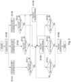
- Fig. 4 is a flowchart showing a method of controlling the drive device 1.
- the damper 9 is in the disabled mode when the construction machine 100 is stopped or in normal operation.
- normal operation refers to operation in which the construction machine 100 is not subjected to excessive impact loads.
- step ST100 when an impact load is applied to the construction machine 100 (step ST100), the impact load is detected by any of the impact detection sensors 8 installed in the BM, AM, and BKT coupling portions. If the impact load is detected by the impact detection sensor 8 in the BM coupling portion (step ST110), the control unit 20 determines whether or not the detected impact load exceeds the impact load threshold for the BM coupling portion (step ST111).
- step ST111 If the determination in step ST111 is "No", i.e., the impact load detected from the BM coupling portion is less than or equal to the impact load threshold, the damper 9 remains in the disabled mode (step ST140). If the determination in step ST111 is "Yes”, i.e., the impact load detected from the BM coupling portion exceeds the impact load threshold, the control unit 20 switches the damper 9 to the enabled mode (step ST150). The impact load transmitted from the BM coupling portion to the swing bracket 105 is then mitigated by the damper 9. As a result, the load applied to the BM coupling portion is mitigated.
- the control unit 20 determines whether or not the impact load detected from the BM coupling portion has been reduced to less than or equal to the impact load threshold (step ST112). If the determination in step ST112 is "No", i.e., the impact load detected from the BM coupling portion has not been reduced to less than or equal to the impact load threshold, the damper 9 remains in the enabled mode (step ST150). If the determination in step ST112 is "Yes”, i.e., the impact load detected from the BM coupling portion has been reduced to less than or equal to the impact load threshold, the control unit 20 switches the damper 9 to the disabled mode (step ST160). The construction machine 100 returns to normal operation or stops.
- step ST120 If the impact load is detected by the impact detection sensor 8 in the AM coupling portion (step ST120), the control unit 20 determines whether or not the detected impact load exceeds the impact load threshold for the AM coupling portion (step ST121). If the determination in step ST121 is "No", i.e., the impact load detected from the AM coupling portion is less than or equal to the impact load threshold, the damper 9 remains in the disabled mode (step ST140).
- step ST121 If the determination in step ST121 is "Yes", i.e., the impact load detected from the AM coupling portion exceeds the impact load threshold, the control unit 20 switches the damper 9 to the enabled mode (step ST150). The impact load transmitted from the AM coupling portion to the swing bracket 105 is then mitigated by the damper 9. As a result, the load applied to the AM coupling portion is mitigated.
- the control unit 20 determines whether or not the impact load detected from the AM coupling portion has been reduced to less than or equal to the impact load threshold (step ST122). If the determination in step ST122 is "No", i.e., the impact load detected from the AM coupling portion has not been reduced to less than or equal to the impact load threshold, the damper 9 remains in the enabled mode (step ST150). If the determination in step ST122 is "Yes”, i.e., the impact load detected from the AM coupling portion has been reduced to less than or equal to the impact load threshold, the control unit 20 switches the damper 9 to the disabled mode (step ST160). The construction machine 100 returns to normal operation or stops.
- step ST130 If the impact load is detected by the impact detection sensor 8 in the BKT coupling portion (step ST130), the control unit 20 determines whether or not the detected impact load exceeds the impact load threshold for the BKT coupling portion (step ST131). If the determination in step ST131 is "No", i.e., the impact load detected from the BKT coupling portion is less than or equal to the impact load threshold, the damper 9 remains in the disabled mode (step ST140).
- step ST131 If the determination in step ST131 is "Yes", i.e., the impact load detected from the BKT coupling portion exceeds the impact load threshold, the control unit 20 switches the damper 9 to the enabled mode (step ST150).
- the impact load transmitted from the BKT coupling portion to the swing bracket 105 is then mitigated by the damper 9. As a result, the load applied to the BKT coupling portion is mitigated.
- the control unit 20 determines whether or not the impact load detected from the BKT coupling portion has been reduced to less than or equal to the impact load threshold (step ST132). If the determination in step ST132 is "No", i.e., the impact load detected from the BKT coupling portion has not been reduced to less than or equal to the impact load threshold, the damper 9 remains in the enabled mode (step ST150). If the determination in step ST132 is "Yes”, i.e., the impact load detected from the BKT coupling portion has been reduced to less than or equal to the impact load threshold, the control unit 20 switches the damper 9 to the disabled mode (step ST160). The construction machine 100 returns to normal operation or stops.
- the drive device 1 includes the electric actuator 2 and the damper 9. Therefore, the impact loads applied to the coupling portions (the BM coupling portion, the AM coupling portion, and the BKT coupling portion) can be reduced by the damper 9. As a result, the impact loads applied to the electric actuators 2 provided in the coupling portions can be mitigated. Thus, damage to the electric actuators 2 can be prevented.
- the damper 9 is configured to operate in the enabled mode, which enables the function of mitigating the impact loads applied to the swing bracket 105 (rod 16), and the disabled mode, which disables the function of mitigating the impact loads applied to the swing bracket 105 (rod 16). This prevents the damper 9 from acting constantly and thus imparting a load on the electric actuators 2. Therefore, reduction in the drive efficiency of the drive device 1 can be prevented.
- the damper 9 is set to the enabled mode when the impact load applied to the coupling portions (BM coupling portion, AM coupling portion, and BKT coupling portion) exceeds a predetermined impact load threshold.
- the damper 9 is set to the disabled mode when the impact load applied to the coupling portions (BM coupling portion, AM coupling portion, and BKT coupling portion) is less than or equal to a predetermined impact load threshold.
- the first embodiment described above is based on the case where the damper 9 is connected to the slewable upper structure 101b and the swing bracket 105.
- the damper 9 may be provided in any manner to be connected to two members (first and second members) provided rotatably.
- the drive device 1 should include, in addition to the damper 9, a first member, a second member rotatable relative to the first member so as to move closer to and away from the first member, and an electric actuator 2 that rotates the second member relative to the first member. It is also possible that the drive device 1 is not used in the construction machine 100.
- the first and second members are, for example, the boom 102, the arm 103, the bucket 104 or the like. If use of the drive device 1 is limited to the construction machine 100, it is also possible that the damper 9 cannot be switched between the enabled mode and the disabled mode. The damper 9 should act constantly. In this case, the damper 9 is provided to be connected to the slewable upper structure 101b and the swing bracket 105. This configuration prevents the damper 9 from imparting a load to the electric actuator 2 while acting constantly. Therefore, it is possible to prevent reduction in the drive efficiency of the drive device 1 while preventing damage to the electric actuator 2 caused by the impact loads.
- the first embodiment described above is based on the case where the damper 9 is an extensible cylinder damper, for example.
- the damper 9 may be configured in any manner to have the ability to mitigate the impact loads on the swing bracket 105 or the like and have the enabled mode, which enables the function of mitigating the impact loads, and the disabled mode, which disables the function of mitigating the impact loads.
- the damper 9 may be a rotary damper instead of an extensible cylinder damper.
- the first embodiment described above is based on the case where the damper 9 has a cylinder 11 filled with a hydraulic fluid.
- the resistance produced by the flow of the hydraulic fluid mitigates the impact loads applied to the rod 16.
- the invention is not limited to such configuration. Any configuration is possible as long as the cylinder 11 is filled with a fluid. Any configuration is possible as long as the resistance produced by the flow of the fluid mitigates the impact loads applied to the rod 16.
- a gas such as the air can be used in place of the hydraulic fluid.
- damper 9 may be configured in the following manner.
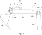
- FIG. 5 schematically illustrates configuration of a drive device 201 according to a second embodiment.
- the same elements as in the first embodiment described above will be denoted by the same reference numerals and detailed descriptions thereof will be omitted (this also applies to the embodiments and variations described further below).
- the drive device 201 includes an electro-hydraulic actuator 30 in place of the damper 9 of the first embodiment. This is the difference between the first embodiment and the second embodiment.
- Fig. 5 shows the case where the electro-hydraulic actuator 30 is provided to be connected to the arm 103 and the bucket 104.
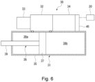
- Fig. 6 schematically illustrates configuration of the electro-hydraulic actuator 30.
- the electro-hydraulic actuator 30 includes a hydraulic cylinder 31, a hydraulic pump 32 for circulating a hydraulic fluid to the hydraulic cylinder 31, a tank 33 for storing the hydraulic fluid, and a hydraulic actuator-adapted electric motor 34 for driving the hydraulic pump 32.
- the hydraulic cylinder 31 includes a cylinder 35 and a piston rod 36 that slides within the cylinder 35 along the axial direction of the cylinder 35.
- the hydraulic actuator-adapted electric motor 34 is, for example, a brushless electric motor.
- the hydraulic actuator-adapted electric motor 34 has a driver 45 integrated thereon for selectively supplying current to the coil (not shown).
- the driver 45 is connected to, for example, the control unit 20.
- the control unit 20 controls the driving of the hydraulic actuator-adapted electric motor 34.
- the cylinder 35 of the electro-hydraulic actuator 30 is fixed to the arm 103, for example.
- the rod 39 of the piston rod 36 of the electro-hydraulic actuator 30 is fixed to the bucket 104, for example.
- the electric actuator 2 is driven, and the electro-hydraulic actuator 30 is driven as well.
- these two actuators 2, 30 are driven and controlled in synchronization by the control unit 20.
- the driving forces of these two actuators 2, 30 are used to drive the bucket 104 relative to the arm 103, for example.
- the drive device 201 includes the electro-hydraulic actuator 30 in place of the damper 9 of the first embodiment.
- This configuration produces the same effects as in the first embodiment described above.
- the electro-hydraulic actuator 30 the movement of the hydraulic fluid is allowed and blocked between the hydraulic chambers 38a and 38b via the hydraulic pump 32. This allows the damper to be put into the enabled mode and the disabled mode, as in the first embodiment described above.
- the electro-hydraulic actuator 30 can assist in driving the electric actuator 2. Therefore, the drive efficiency of the drive device 201 can be increased.
- Fig. 7 schematically illustrates configuration of the drive device 201 according to the first variation of the second embodiment.
- the grapple 106 and the cylinder 35 of the electro-hydraulic actuator 30 may be connected via tubes 40a and 40b.
- the hydraulic fluid in the cylinder 35 is used as the hydraulic power source for driving the grapple 106.
- the tubes 40a, 40b are tubes with high pressure resistance, such as high-pressure tubes or metal piping.
- the attachment can be driven without additional components. This allows for greater versatility of the equipment on which the drive device 201 is installed, such as the construction machine 100, and also prevents the increase in the number of parts.
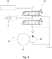
- Fig. 8 is a hydraulic circuit diagram of the drive device 201 according to the second variation of the second embodiment.
- control valves 41, 42 may be provided in the electro-hydraulic actuator 30 included in the drive device 201.
- the control valves 41, 42 are provided between the hydraulic pump 32 and the attachment (grapple 106) or the hydraulic cylinder 31.
- the driving of the control valves 41, 42 is controlled by the control unit 20.
- control valves 41, 42 are used as follows.
- the control valves 41, 42 adjust the flow rate of the hydraulic fluid supplied from the hydraulic pump 32 to the attachment (grapple 106) and the hydraulic cylinder 31.
- the attachment (grapple 106) and the hydraulic cylinder 31 can be driven efficiently by the drive device 201 having a simplified configuration.
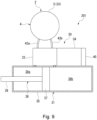
- Fig. 9 schematically illustrates configuration of the drive device 201 according to the third variation of the second embodiment.
- the electro-hydraulic actuator 30 does not necessarily include the tank 33.
- the case 5 of the electric actuator 2 may serve as the tank 33.
- the case 5 of the speed reducer 4 is filled with the hydraulic fluid (lubricating fluid) for the purpose of suppressing the wear of the reduction mechanism 6. This hydraulic fluid is used to drive the hydraulic cylinder 31.
- the case 5 is connected to the hydraulic pump 32 via the tubes 43a, 43b.
- the tubes 43a, 43b are tubes with high pressure resistance, such as high-pressure tubes or metal piping.
- the hydraulic pump 32 supplies the hydraulic fluid in the case 5 to the hydraulic cylinder 31 or discharges the hydraulic fluid from the hydraulic cylinder 31, thereby driving the hydraulic cylinder 31.
- the speed reducer 4 having the case 5, or the tubes 43a, 43b are provided with a filtering portion (not shown) for filtering the hydraulic fluid in the case 5 that is sucked by the hydraulic pump 32.
- the filtering portion is, for example, a magnet or filter that attracts the wear debris.
- the case 5 of the electric actuator 2 serves as the tank 33 for storing the hydraulic fluid. This reduces the number of parts in the electro-hydraulic actuator 30, allowing the entire drive device 201 to have a smaller size and a smaller weight. Therefore, the drive efficiency of the drive device 201 can be further increased.
- the tubes 43a, 43b may be exposed to the outside air or may be housed inside the electric actuator 2 or the electro-hydraulic actuator 30. When the tubes 43a, 43b are exposed to the outside air, heat can be dissipated from the hydraulic fluid flowing through the tubes 43a, 43b.
- the hydraulic fluid cooled when flowing through the tubes 43a, 43b lubricates the speed reducer 4, the hydraulic pump 32, and the hydraulic cylinder 31. This allows the reduction gear 4, the hydraulic pump 32, the hydraulic cylinder 31 and the like to be efficiently cooled by the hydraulic fluid.
- the amount of iron debris in the hydraulic fluid flowing through the tubes 43a, 43b may be detected.
- the amount of iron debris is greater than a predetermined value, it can be determined that abnormal wear has occurred in the reduction mechanism 6, the hydraulic pump 32, or the like.
- detecting the amount of iron powder in the hydraulic fluid flowing through the tubes 43a, 43b makes it possible to detect failures of the electric actuator 2 or the electro-hydraulic actuator 30.
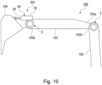
- Fig. 10 schematically illustrates configuration of the drive device 201 according to the fourth variation of the second embodiment.
- the electric actuator 2 and the electro-hydraulic actuator 30 may be integrated together.
- the cylinder 35 of the electro-hydraulic actuator 30 is fixed to the arm 103.
- the cylinder 35 is fixed to the case 5 of the electric actuator 2.
- the electro-hydraulic actuator 30 rotates and moves as the electric actuator 2 drives.
- the driving force of the electric actuator 2 is transmitted to the bucket 104 via the electro-hydraulic actuator 30, and the bucket 104 is driven by this driving force.
- the electric actuator 2 and the electro-hydraulic actuator 30 may separately drive.
- the electric actuator 2 and the electro-hydraulic actuator 30 may synchronously drive.
- the sum of the amount of driving of the electric actuator 2 and the amount of driving of the electro-hydraulic actuator 30 (the amount of extension and contraction of the rod 39) is the amount of movement of the bucket 104 relative to the arm 103.
- the case 5 may serve as the tank 33, or the tank 33 may be installed in the electro-hydraulic actuator 30.
- the electric actuator 2 and the electro-hydraulic actuator 30 are integrated together.
- the drive device 201 may be used to drive the arm 103 relative to the boom 102 or to drive the boom 102 relative to the swing bracket 105.
- the electro-hydraulic actuator 30 may be provided to be connected to the boom 102 and the arm 103, or the electro-hydraulic actuator 30 may be provided to be connected to the swing bracket 105 and the boom 102. It is also possible to integrate the electric actuator 2 and the electro-hydraulic actuator 30 in each of the BM coupling portion and the AM coupling portion.
- the electro-hydraulic actuator 30 having the hydraulic fluid serving as a drive source.
- the invention is not limited to such configuration. Electric fluid actuators using various fluids as a drive source may be used.
- the hydraulic cylinder 31 and the hydraulic pump 32 may drive with any fluid stored in the tank.
- the fluid is not limited to a liquid but may be a gas.
- the electric actuator 2 includes the actuator-adapted electric motor 3 and the speed reducer 4 integrated with the actuator-adapted electric motor 3.
- the electric actuator 2 may be configured in any manner to drive the two members (first and second members) provided rotatably.
- the electric actuator 2 may be a linear actuator.
- FIG. 11 schematically illustrates configuration of a drive device 301 according to the third embodiment.
- the drive device 301 according to the third embodiment includes a hydraulic actuator 50 (an example of the fluid rotator recited in the claims) in place of the damper 9 of the first embodiment.
- the third embodiment is different from the first and second embodiments.
- the external appearance of the electric actuator 2 according to the third embodiment differs from that of the electric actuator 2 according to the first embodiment shown in Fig. 2 , but the basic configuration is the same.
- the electric actuator 2 according to the third embodiment includes the actuator-adapted electric motor 3 and the speed reducer 4 integrated with the actuator-adapted electric motor 3.
- the actuator-adapted electric motor 3 includes an outer flange portion 21.
- the outer flange portion 21 is, for example, a fixing portion (an example of the electric rotator fixing portion recited in the claims) for fixing the electric actuator 2 to the boom 102, the arm 103, the bucket 104, or the swing bracket 105 at the BM coupling portion, the AM coupling portion, or the BKT coupling portion.
- the electric actuator 2 in the third embodiment is an example of the electric rotator recited in the claims.
- the output unit 7 of the electric actuator 2 in the third embodiment is an example of the electric rotator output unit recited in the claims.
- the hydraulic actuator 50 includes a suction/discharge unit 52 for sucking the hydraulic fluid from the tank 33 or discharging the hydraulic fluid to the tank 33, and a drive unit 53 that is rotated by the hydraulic fluid sucked in through the suction/discharge unit 52 as a power source.
- the hydraulic actuator 50 is located coaxially with the electric actuator 2.
- the suction/discharge unit 52 and the drive unit 53 are arranged in the axial direction.
- the hydraulic actuator 50 is disposed such that the drive unit 53 and the output unit 7 (case 5) of the electric actuator 2 are opposed to each other in the axial direction.
- the suction/discharge unit 52 has two suction/discharge ports 54a, 54b.
- the two suction/discharge ports 54a, 54b are connected to the tank 33 via tank channels 71.
- a relief valve 72 and control valves 73 are provided on the middle of the tank channels 71.
- the hydraulic fluid is sucked into or discharged from the drive unit 53 via the suction/discharge ports 54a, 54b.
- the relief valve 72 restricts the pressure of the hydraulic fluid sucked into the suction/discharge unit 52 from the tank 33.
- the control valves 73 control the flow of the hydraulic fluid into the tank channels 71.
- the suction/discharge unit 52 has an outer flange portion 55.
- the outer flange portion 55 is, for example, a fixing portion (an example of the fluid rotator fixing portion recited in the claims) for fixing the hydraulic actuator 50 to the boom 102, the arm 103, the bucket 104, or the swing bracket 105 at the BM coupling portion, the AM coupling portion, or the BKT coupling portion.
- the drive unit 53 includes a case 56, and a rotor portion 57 and a valve plate 58 housed in the case 56.
- the rotor portion 57 includes an internal gear 61 and an external gear 62 located radially inside the internal gear 61.
- the internal gear 61 is shaped annularly.
- the outer circumference of the internal gear 61 is fixed to the case 56.
- Internal teeth 61a are provided on the inner circumference of the internal gear 61.
- the outer circumference of the external gear 62 has external teeth 62a that mesh with the internal teeth 61a.
- a plurality of volume chambers 63 are formed between the internal gear 61 and the external gear 62. Supplying the hydraulic fluid to these volume chambers 63 causes planetary motion of the external gear 62 radially inside the internal gear 61.
- the valve plate 58 is located on the suction/discharge unit 52 side of the case 56. The valve plate 58 is fixed to the case 56.
- the valve plate 58 has a port 58a that allows communication between the suction/discharge unit 52 and predetermined one of the volume chambers 63.
- the valve plate 58 supplies to the predetermined one of the volume chambers 63 the hydraulic fluid supplied from the suction/discharge unit 52 or drains the hydraulic fluid from the predetermined one of the volume chambers 63 via the port 58a.
- the planetary motion of the external gear 62 radially inside the internal gear 61 causes shift of the meshing position between the internal gear 61 and the external gear 62.
- the rotational force is thus generated in the internal gear 61.
- the case 56 serves as the output unit (an example of the fluid rotator output unit recited in the claims) 60 of the hydraulic actuator 50 that rotates relative to the suction/discharge unit 52 (the outer flange portion 55).
- the valve plate 58 As the valve plate 58 is rotated, the hydraulic fluid is supplied to different volume chambers 63. In this way, the rotational force is continuously generated in the internal gear 61.
- the case 5 (output unit 7) of the electric actuator 2 and the case 56 (output unit 60) of the hydraulic actuator 50 are connected via a member corresponding to the member to which the outer flange portions 21, 55 are fixed in the BM coupling portion, the AM coupling portion, and the BKT coupling portion.
- the cases 5, 56 are connected via the bucket 104 (see also Fig. 1 ).
- the bucket 104 corresponds to the drive member recited in the claims.
- the drive device 301 is provided in the BKT coupling portion.
- the outer flange portions 21, 55 are fixed to the arm 103, and the cases 5, 56 are fixed to the bucket 104.
- the tank channel 71 is opened by the control valve 73.
- the rotation of the case 56 causes the valve plate 58 to rotate integrally with the case 56.
- the hydraulic fluid in the tank 33 is then supplied to the volume chambers 63 via the suction/discharge unit 52 and the valve plate 58.
- the rotational force is also generated in the electro-hydraulic actuator 30.
- This rotational force in the electro-hydraulic actuator 30 assists in driving the electric actuator 2.
- the driving forces of these two actuators 2, 50 are used to drive the bucket 104 relative to the arm 103, for example.
- a braking mode in which the hydraulic actuator 50 applies a braking force to the electric actuator 2
- a regenerative mode in which the electric actuator 2 provides regenerative energy.
- the control valve 73 blocks the tank channel 71. This blocks the circulation (flow) of the hydraulic fluid between the hydraulic actuator 50 and the tank 33 and prevents the rotation of the case 56. Therefore, the hydraulic actuator 50 applies a braking force to the electric actuator 2.
- the tank channel 71 is opened by the control valve 73 in the same manner as described above for the operation of the drive device. This allows the cases 5, 56 to rotate freely. As a result, regenerative energy can be obtained by the actuator-adapted electric motor 3 of the electric actuator 2.
- the hydraulic actuator 50 includes the rotor portion 57 having the volume chambers 63, and a valve plate 58 for supplying the hydraulic fluid to and draining the hydraulic fluid from the volume chambers 63.
- the valve plate 58 rotates integrally with the output unit 60 (case 56). This ensures that the electric actuator 2 and the hydraulic actuator 50 can be synchronized. Therefore, control of driving of the hydraulic actuator 50 can be simplified, and the drive efficiency of the drive device 301 can be further increased.
- the rotor portion 57 includes the internal gear 61 and the external gear 62 located radially inside the internal gear 61 and configured to perform planetary motion.
- the volume chambers 63 are formed between the internal gear 61 and the external gear 62.
- the method of controlling the drive device 301 has the regenerative mode in which the control valve 73 opens the tank channel 71. This allows the cases 5, 56 to rotate freely. As a result, regenerative energy can be obtained by the actuator-adapted electric motor 3 of the electric actuator 2.
- the control valve 73 blocks the tank channel 71. This blocks the circulation (flow) of the hydraulic fluid between the hydraulic actuator 50 and the tank 33 and prevents the rotation of the case 56. Therefore, the hydraulic actuator 50 can apply a braking force to the electric actuator 2.
- the electric actuator 2 includes the actuator-adapted electric motor 3 and the speed reducer 4 integrated with the actuator-adapted electric motor 3.
- the electric actuator 2 can be any electric rotational device that rotates coaxially with the electric actuator 50.
- the electric actuator 2 does not necessarily include the speed reducer 4.
- the actuator-adapted electric motor 3 of the electric actuator 2 includes the outer flange portion 21.
- the outer flange portion 21 is a fixing portion (an example of the electric rotator fixing portion recited in the claims) for fixing the electric actuator 2 to the boom 102, the arm 103, the bucket 104, or the swing bracket 105.
- a description was given of the case where the outer flange portion 55 is provided on the suction/discharge unit 52 of the hydraulic actuator 50.
- the outer flange portion 55 is a fixing portion (an example of the fluid rotator fixing portion recited in the claims) for fixing the hydraulic actuator 50 to the boom 102, the arm 103, the bucket 104, or the swing bracket 105.
- the invention is not limited to such configuration.
- Each of the fixing portions can be configured in any manner to fix the electric actuator 2 or the hydraulic actuator 50 to the boom 102, the arm 103, the bucket 104, or the swing bracket 105.
- the invention is not limited to such configuration.
- the hydraulic actuator 50 can be driven in any manner to assist the driving of the electric actuator 2.
- the control valves 73 are omitted and the switching between the regenerative mode and the braking mode is not performed.
- the relief valve 72 may be replaced with a control valve. This may mitigate a sudden pressure increase in the hydraulic actuator 50.
- the hydraulic circuit of the hydraulic actuator 50 can be an open circuit.
- a what is called a counterbalance valve is preferably provided on the middle of the channel to maintain the reverse driving force of the hydraulic actuator 50.
- the hydraulic actuator 50 includes the volume chambers 63 defined by the internal gear 61 and the external gear 62 and includes the valve plate 58 that supplies and drains the hydraulic fluid to and from the volume chambers 63.
- a description was given of the case where the valve plate 58 is rotated from the outside (case 56) to obtain the driving force of the hydraulic actuator 50.
- the hydraulic actuator 50 can be configured in any manner to provide the driving force by having the output unit rotated from the outside.
- the hydraulic actuator 50 may be what is called a swash plate hydraulic motor.
- This type of hydraulic motor includes a swash plate, a plurality of pistons that move along the swash plate around a rotational axis, a timing plate provided between the swash plate and the pistons, and a cylinder block having the pistons slidably inserted therein and configured to rotate around the rotational axis.
- the timing plate functions similarly to the valve plate 58.
- the cylinder block functions similarly to the rotor portion 57.
- rotation of the timing plate causes the cylinder block to rotate and the pistons to reciprocate in the cylinder block.
- the hydraulic fluid is supplied into or drained from the cylinder block, and a rotational force is generated in the cylinder block.
- the driving force of the hydraulic motor can be obtained.
- the invention is also not limited to the embodiments described above. Various modifications can be made to these embodiments without departing from the true scope and spirit of the present invention.
- An output shaft may be provided separately from the case 5.
- a member formed of multiple components may be integrated into a single component, or conversely, a member formed of a single component may be divided into multiple components. Irrespective of whether or not the components are integrated, they are acceptable as long as they are configured to attain the object of the invention.
Landscapes
- Engineering & Computer Science (AREA)
- General Engineering & Computer Science (AREA)
- Structural Engineering (AREA)
- Civil Engineering (AREA)
- Mining & Mineral Resources (AREA)
- Mechanical Engineering (AREA)
- Power Engineering (AREA)
- Physics & Mathematics (AREA)
- Aviation & Aerospace Engineering (AREA)
- Acoustics & Sound (AREA)
- Fluid Mechanics (AREA)
- Operation Control Of Excavators (AREA)
- Fluid-Pressure Circuits (AREA)
- Retarders (AREA)
Abstract
The present invention relates to a drive device (1) and a method of controlling the drive device. The drive device (1) according to the invention includes a first member (102, 103, 104, 105, 106), a second member (102, 103, 104, 105, 106), an electric actuator (2), and a damper (9). The damper (9) is configured to drive in an enabled mode and a disabled mode, the enabled mode enables a function of mitigating an impact load applied to either one of the first member and the second member, and the disabled mode disables the function of mitigating an impact load applied to either one of the first member and the second member.
Description
- The present invention relates to a drive device and a method of controlling the drive device.
- Devices using hydraulic pressure such as hydraulic motors and hydraulic cylinders are known as, for example, drive devices for hydraulic excavators and other construction machines. Devices using electric power such as electric motors and linear actuators are also known to be used in place of the devices using hydraulic pressure.
- When electric motors or linear actuators are used as drive devices, the impact loads applied to the electric motors or linear actuators used as described above could damage the drive devices. To address this issue, various techniques have been proposed to absorb the impact loads. For example,
Patent Literature 1 discloses a technique in which a mechanism composed of a disc spring or a torsion spring is provided in a linear actuator. This mechanism for absorbing the impact loads operates in the event of an overload to prevent damage to the linear actuator. - Patent Literature 1: Publication of
Japanese Patent No. 5497198 - However, the conventional technique described above has an issue that the above configuration is not applicable to the case where an electric motor is used as a drive device for rotational drive. Furthermore, when the mechanism for absorbing the impact loads is used in an actual construction machine, it would need to be configured to withstand large impact loads, resulting in a larger size of the device. Thus, drive efficiency of the drive device is reduced.
- The present invention provides a drive device and a method of controlling the drive device capable of mitigating the impact loads applied to the rotationally driving device and preventing reduction in drive efficiency.
- A drive device according to one aspect of the invention includes: a first member; a second member rotatable relative to the first member so as to move closer to and away from the first member; an electric actuator configured to rotate the second member relative to the first member; and a damper connected to the first member and the second member. The damper is configured to drive in an enabled mode and a disabled mode, the enabled mode enables a function of mitigating an impact load applied to either one of the first member and the second member, and the disabled mode disables the function of mitigating an impact load applied to either one of the first member and the second member.
- This configuration allows the damper to mitigate the impact load applied to the electric actuator driving rotationally. Damage to the electric actuator can be prevented. The damper is configured to operate in the enabled mode, which enables the function of mitigating the impact load, and the disabled mode, which disables the function of mitigating the impact load. This prevents the damper from acting constantly and thus imparting a load on the electric actuator. Therefore, reduction in the drive efficiency of the drive device can be prevented.
- A drive device according to another aspect of the invention includes: a boom rotatably coupled to a swing bracket provided on a vehicle body; an arm rotatably coupled to the boom; an attachment rotatably coupled to the arm; an electric actuator provided in at least one of a coupling portion between the swing bracket and the boom, a coupling portion between the boom and the arm, or a coupling portion between the arm and the attachment; and a damper connected to the vehicle body and the swing bracket and configured to mitigate an impact load applied to the swing bracket.
- This configuration allows impact loads applied to the arm, boom, and attachment to be transmitted to the swing bracket and then to the damper via the swing bracket before the impact loads are applied to the electric actuator. Since the damper can mitigate the impact loads, it is possible to mitigate the impact loads applied to the electric actuator driving rotationally and to prevent damage to the electric actuator. Since the damper is connected to the vehicle body and the swing bracket, it can be prevented that a load is imparted to the electric actuator even if the damper acts constantly. Therefore, reduction in the drive efficiency of the drive device can be prevented.
- In the above configuration, the damper may include an electric fluid actuator, The electric fluid actuator may include: a cylinder; a fluid pump configured to circulate a fluid to the cylinder; and a fluid actuator-adapted electric motor configured to drive the fluid pump.
- In the above configuration, the electric actuator may include: an actuator-adapted electric motor; and a speed reducer integrated with the actuator-adapted electric motor. The speed reducer may include: a case; and a reduction mechanism housed in the case and configured to decelerate rotation input from the actuator-adapted electric motor and output the decelerated rotation. The case may serve as a tank for storing the fluid.
- In the above configuration, the electric fluid actuator and the electric actuator may be integrated together.
- In the above configuration, the fluid pump and the case may be connected via a tube conveying the fluid, and the tube may be exposed to an outside air.
- A drive device according to another aspect of the invention includes: a drive member; and a fluid rotator and an electric rotator configured to drive the drive member. The fluid rotator and the electric rotator are located coaxially, a fluid rotator output unit for outputting rotation of the fluid rotator and an electric rotator output unit for outputting rotation of the electric rotator are opposed to each other, and the fluid rotator output unit and the electric rotator output unit are connected via the drive member.
- With such configuration, when an impact load is applied to the drive member, the fluid rotator can mitigate the impact load applied to the electric rotator. This can mitigate the impact load applied to the electric rotator driving rotationally and prevent damage to the electric rotator. Since the fluid rotator can assist the drive of the electric rotator, the drive efficiency of the drive device can be improved.
- In the above configuration, it is also possible that the fluid rotator includes a fluid rotator fixing portion located on an opposite side to the fluid rotator output unit in an axial direction, the fluid rotator output unit is rotated relative to the fluid rotator fixing portion, the electric rotator includes an electric rotator fixing portion located on an opposite side to the electric rotator output unit in the axial direction, the electric rotator output unit is rotated relative to the electric rotator fixing portion, and the fluid rotator fixing portion and the electric rotator fixing portion are fixed to a fixing member other than the drive member.
- In the above configuration, it is also possible that the fluid rotator includes: a rotor portion having a volume chamber with a liquid supplied to and drained from the volume chamber; and a valve plate having a port for supplying and draining the liquid into and from the volume chamber. It is also possible that the rotor portion generates a rotational force with the liquid supplied to and drained from the volume chamber, and the valve plate rotates integrally with the fluid rotator output unit.
- In the above configuration, it is also possible that the rotor portion includes: an internal gear; and an external gear configured to perform planetary motion radially inside the internal gear. It is also possible that the volume chamber is formed between the internal gear and the external gear.
- A method of controlling a drive device according to one aspect of the invention controls the drive device. The drive device includes: a first member; a second member rotatable relative to the first member so as to move closer to and away from the first member; an electric actuator configured to rotate the second member relative to the first member; and a damper connected to the first member and the second member, and the damper is configured to drive in an enabled mode and a disabled mode, the enabled mode enables a function of mitigating an impact load applied to either one of the first member and the second member, and the disabled mode disables the function of mitigating an impact load applied to either one of the first member and the second member. The control method includes: putting the damper into the enabled mode when an impact load applied to either one of the first member and the second member exceeds a predetermined threshold; and putting the damper into the disabled mode when an impact load applied to either one of the first member and the second member is less than or equal to the predetermined threshold.
- This method allows the damper to mitigate the impact load applied to the electric actuator. By switching the damper between the enabled mode, which enables the function of mitigating the impact load, and the disabled mode, which disables the function of mitigating the impact load, the damper can be prevented from imparting a load to the electric actuator. Therefore, reduction in the drive efficiency of the drive device can be prevented.
- A method of controlling a drive device according to one aspect of the invention controls the drive device. The drive device includes: a drive member; a fluid rotator and an electric rotator configured to drive the drive member, and a tank channel configured to return a fluid for driving the fluid rotator to a tank, the fluid rotator and the electric rotator are located coaxially, a fluid rotator output unit for outputting rotation of the fluid rotator and an electric rotator output unit for outputting rotation of the electric rotator are opposed to each other, and the fluid rotator output unit and the electric rotator output unit are connected via the drive member. The control method includes: opening the tank channel to obtain regenerative energy by the electric rotator; and blocking the tank channel to cause the fluid rotator to function as a brake for braking rotation of the electric rotator.
- This method allows the hydraulic motor to function as a brake for the electric motor, thus simplifying the drive device. The regenerative energy can be obtained by the electric motor without being inhibited by the hydraulic motor. Therefore, the drive efficiency of the drive device can be increased.
- The drive device and the method of controlling the drive device described above are capable of mitigating the impact loads applied to the rotationally driving device and preventing reduction in drive efficiency.
-
-
Fig. 1 schematically illustrates configuration of a construction machine according to a first embodiment of the invention. -
Fig. 2 schematically illustrates configuration of an electric actuator according to the first embodiment of the invention. -
Fig. 3 schematically illustrates configuration of a damper according to the first embodiment of the invention. -
Fig. 4 is a flowchart showing a method of controlling the drive device according to the first embodiment of the invention. -
Fig. 5 schematically illustrates configuration of a drive device according to a second embodiment of the invention. -
Fig. 6 schematically illustrates configuration of an electric hydraulic actuator according to the second embodiment of the invention. -
Fig. 7 schematically illustrates configuration of a drive device according to a first variation of the second embodiment of the invention. -
Fig. 8 is a hydraulic circuit diagram of a drive device according to a second variation of the second embodiment of the invention. -
Fig. 9 schematically illustrates configuration of a drive device according to a third variation of the second embodiment of the invention. -
Fig. 10 schematically illustrates configuration of a drive device according to a fourth variation of the second embodiment of the invention. -
Fig. 11 schematically illustrates configuration of a drive device according to a third embodiment of the invention. - The embodiments of the present invention will be hereinafter described with reference to the drawings.
-
Fig. 1 schematically illustrates configuration of aconstruction machine 100 including adrive device 1 according to a first embodiment. Theconstruction machine 100 is a type of excavator, such as a power shovel. As shown inFig. 1 , theconstruction machine 100 includes: avehicle body 101 having anundercarriage 101a and a slewableupper structure 101b; and aboom 102, anarm 103, a bucket (an example of an attachment recited in the claims) 104, and a plurality ofdrive devices 1 provided on thevehicle body 101. In the following description, the "top-bottom direction" refers to the top-bottom direction of theconstruction machine 100 placed on the road surface, and the "front-rear direction" and the "left-right direction" refer to the front-rear direction and the left-right direction with respect to the slewableupper structure 101b. - The slewable
upper structure 101b is slewable relative to theundercarriage 101a around a rotational axis extending in the top-bottom direction. Theproximal end 102a of theboom 102 is rotatably coupled to the slewableupper structure 101b via aswing bracket 105. Theproximal end 103a of thearm 103 is rotatably coupled to thedistal end 102b of theboom 102. Thebucket 104 is rotatably coupled to thedistal end 103b of thearm 103. - The first rotational axis J1 between the
swing bracket 105 and theboom 102, the second rotational axis J2 between theboom 102 and thearm 103, and the third rotational axis J3 between thearm 103 and thebucket 104 extend along the left-right direction. Theswing bracket 105 is provided on the slewableupper structure 101b so as to be swingable in the left-right direction. Anelectric actuator 2 is provided in each of the coupling portion between theswing bracket 105 and theboom 102, the coupling portion between theboom 102 and thearm 103, and the coupling portion between thearm 103 and thebucket 104. Each of theelectric actuators 2 constitutes a part of thedrive device 1. - A description will now be first given of the
electric actuator 2 with reference toFig. 2. Fig. 2 schematically illustrates configuration of theelectric actuator 2. As shown inFig. 2 , theelectric actuator 2 includes an actuator-adaptedelectric motor 3 and aspeed reducer 4 integrated with the actuator-adaptedelectric motor 3. The actuator-adaptedelectric motor 3 and thespeed reducer 4 are arranged in the axial direction. Thespeed reducer 4 includes acase 5 and areduction mechanism 6 housed in thecase 5. - The
reduction mechanism 6 decelerates the rotation input from the actuator-adaptedelectric motor 3 and outputs the decelerated rotation. Thereduction mechanism 6 is constituted by, for example, a plurality of gears. Thecase 5 functions as anoutput unit 7 for thereduction mechanism 6. Theelectric actuator 2 is installed such that the rotational axis of the actuator-adaptedelectric motor 3 and thespeed reducer 4 coincide with the corresponding one of the rotational axes J1 to J3. - For example, in the
electric actuator 2 installed at the coupling portion between theswing bracket 105 and theboom 102, the actuator-adaptedelectric motor 3 is fixed to either one of theswing bracket 105 or theboom 102. Thecase 5 is fixed to the other of theswing bracket 105 or theboom 102. This configuration allows theboom 102 to rotationally drive relative to theswing bracket 105 around the first rotational axis J1. - For example, in the
electric actuator 2 installed at the coupling portion between theboom 102 and thearm 103, the actuator-adaptedelectric motor 3 is fixed to either one of theboom 102 or thearm 103. Thecase 5 is fixed to the other of theboom 102 or thearm 103. This configuration allows thearm 103 to rotationally drive relative to theboom 102 around the second rotational axis J2. - For example, in the
electric actuator 2 installed at the coupling portion between thearm 103 and thebucket 104, the actuator-adaptedelectric motor 3 is fixed to either one of thearm 103 or thebucket 104. Thecase 5 is fixed to the other of thearm 103 or thebucket 104. This configuration allows thebucket 104 to rotationally drive relative to thearm 103 around the third rotational axis J3. - Each
electric actuator 2 is equipped with animpact detection sensor 8. Theimpact detection sensors 8 detect impact loads applied to theboom 102, thearm 103, and thebucket 104. Theimpact detection sensors 8 may be, for example, strain sensors, current sensors, acceleration sensors, or angular velocity sensors. A strain sensor would detect the impact loads applied to theboom 102, thearm 103, or thebucket 104 by, for example, detecting the strain generated in thecase 5. If the strain value exceeds a predetermined threshold, it is determined that theboom 102, thearm 103, or thebucket 104 is subjected to excessive impact loads. - A current sensor detects a current value supplied to the actuator-adapted
electric motor 3. If the current value exceeds a predetermined threshold, it is determined that theboom 102, thearm 103, or thebucket 104 is subjected to excessive impact loads. With an acceleration sensor or an angular velocity sensor, if the degree of speed reduction after driving theboom 102, thearm 103, or thebucket 104 falls below a predetermined threshold, it is determined that theboom 102, thearm 103, or thebucket 104 is subjected to excessive impact loads. The acceleration sensor or the angular velocity sensor can also be installed on theboom 102, thearm 103 or thebucket 104. In the following description, the above thresholds are collectively referred to as impact load thresholds. - The
drive device 1 includes adamper 9 in addition to theelectric actuator 2. Thedamper 9 is provided to be connected to the slewableupper structure 101b and theswing bracket 105. Thedamper 9 mitigates the impact loads applied to theswing bracket 105. In other words, the impact loads applied to theboom 102, thearm 103, or thebucket 104 are transmitted to theswing bracket 105. Therefore, thedamper 9 which mitigates the impact loads applied to theswing bracket 105 resultantly mitigates the impact loads applied to theboom 102, thearm 103, or thebucket 104. -
Fig. 3 schematically shows the configuration of thedamper 9. As shown inFigs. 1 and3 , thedamper 9 is, for example, an extensible cylinder damper. Thedamper 9 includes acylinder 11 and apiston rod 12 that slides within thecylinder 11 along the axial direction of thecylinder 11. The interior of thecylinder 11 is partitioned into twohydraulic chambers piston 13 of thepiston rod 12. Thecylinder 11 is filled with a hydraulic fluid. The twohydraulic chambers channel 14 that allows communication between these twohydraulic chambers channel 14 is provided with an open/close switch 15. The open/close switch 15 allows or blocks the flow of the hydraulic fluid in thechannel 14. - The open/
close switch 15 is connected to thecontrol unit 20 provided on theconstruction machine 100. Thecontrol unit 20 receives signals representing the values detected by theimpact detection sensors 8. Thecontrol unit 20 has impact load thresholds that are set separately for the coupling portion between theswing bracket 105 and the boom 102 (hereinafter referred to as "BM coupling portion"), the coupling portion between theboom 102 and the arm 103 (hereinafter referred to as "AM coupling portion"), and the coupling portion between thearm 103 and the bucket 104 (hereinafter referred to as "BKT coupling portion"). Thecontrol unit 20 controls the opening and closing of the open/close switch 15 based on the signals input from theimpact detection sensors 8 and the impact load thresholds. - In the
damper 9 thus configured, thecylinder 11 is fixed to either one of the slewableupper structure 101b or theswing bracket 105. In thedamper 9, therod 16 of thepiston rod 12 is fixed to the other of the slewableupper structure 101b or theswing bracket 105. When a predetermined amount of impact load is applied to the rod 16 (see the arrow F inFig. 3 ), thepiston 13 is pushed in, and the volumes of the twohydraulic chambers hydraulic chambers rod 16. At this time, the flow of the hydraulic fluid in thechannel 14 is allowed by the open/close switch 15. - On the other hand, when the flow of the hydraulic fluid in the channel is blocked by the open/
close switch 15, the movement of thepiston rod 12 is inhibited. Therefore, thedamper 9 cannot mitigate the impact loads applied to therod 16. In other words, thedamper 9 is configured to operate in an enabled mode, which enables the function of mitigating the impact loads applied to the swing bracket 105 (rod 16), and a disabled mode, which disables the function of mitigating the impact loads applied to the swing bracket 105 (rod 16). - Next, a detailed description is given of a method of controlling the
drive device 1.Fig. 4 is a flowchart showing a method of controlling thedrive device 1. In thedrive device 1, thedamper 9 is in the disabled mode when theconstruction machine 100 is stopped or in normal operation. The term "normal operation" refers to operation in which theconstruction machine 100 is not subjected to excessive impact loads. - As shown in
Fig. 4 , when an impact load is applied to the construction machine 100 (step ST100), the impact load is detected by any of theimpact detection sensors 8 installed in the BM, AM, and BKT coupling portions. If the impact load is detected by theimpact detection sensor 8 in the BM coupling portion (step ST110), thecontrol unit 20 determines whether or not the detected impact load exceeds the impact load threshold for the BM coupling portion (step ST111). - If the determination in step ST111 is "No", i.e., the impact load detected from the BM coupling portion is less than or equal to the impact load threshold, the
damper 9 remains in the disabled mode (step ST140). If the determination in step ST111 is "Yes", i.e., the impact load detected from the BM coupling portion exceeds the impact load threshold, thecontrol unit 20 switches thedamper 9 to the enabled mode (step ST150). The impact load transmitted from the BM coupling portion to theswing bracket 105 is then mitigated by thedamper 9. As a result, the load applied to the BM coupling portion is mitigated. - Subsequently, the
control unit 20 determines whether or not the impact load detected from the BM coupling portion has been reduced to less than or equal to the impact load threshold (step ST112). If the determination in step ST112 is "No", i.e., the impact load detected from the BM coupling portion has not been reduced to less than or equal to the impact load threshold, thedamper 9 remains in the enabled mode (step ST150). If the determination in step ST112 is "Yes", i.e., the impact load detected from the BM coupling portion has been reduced to less than or equal to the impact load threshold, thecontrol unit 20 switches thedamper 9 to the disabled mode (step ST160). Theconstruction machine 100 returns to normal operation or stops. - If the impact load is detected by the
impact detection sensor 8 in the AM coupling portion (step ST120), thecontrol unit 20 determines whether or not the detected impact load exceeds the impact load threshold for the AM coupling portion (step ST121). If the determination in step ST121 is "No", i.e., the impact load detected from the AM coupling portion is less than or equal to the impact load threshold, thedamper 9 remains in the disabled mode (step ST140). - If the determination in step ST121 is "Yes", i.e., the impact load detected from the AM coupling portion exceeds the impact load threshold, the
control unit 20 switches thedamper 9 to the enabled mode (step ST150). The impact load transmitted from the AM coupling portion to theswing bracket 105 is then mitigated by thedamper 9. As a result, the load applied to the AM coupling portion is mitigated. - Subsequently, the
control unit 20 determines whether or not the impact load detected from the AM coupling portion has been reduced to less than or equal to the impact load threshold (step ST122). If the determination in step ST122 is "No", i.e., the impact load detected from the AM coupling portion has not been reduced to less than or equal to the impact load threshold, thedamper 9 remains in the enabled mode (step ST150). If the determination in step ST122 is "Yes", i.e., the impact load detected from the AM coupling portion has been reduced to less than or equal to the impact load threshold, thecontrol unit 20 switches thedamper 9 to the disabled mode (step ST160). Theconstruction machine 100 returns to normal operation or stops. - If the impact load is detected by the
impact detection sensor 8 in the BKT coupling portion (step ST130), thecontrol unit 20 determines whether or not the detected impact load exceeds the impact load threshold for the BKT coupling portion (step ST131). If the determination in step ST131 is "No", i.e., the impact load detected from the BKT coupling portion is less than or equal to the impact load threshold, thedamper 9 remains in the disabled mode (step ST140). - If the determination in step ST131 is "Yes", i.e., the impact load detected from the BKT coupling portion exceeds the impact load threshold, the
control unit 20 switches thedamper 9 to the enabled mode (step ST150). The impact load transmitted from the BKT coupling portion to theswing bracket 105 is then mitigated by thedamper 9. As a result, the load applied to the BKT coupling portion is mitigated. - Subsequently, the
control unit 20 determines whether or not the impact load detected from the BKT coupling portion has been reduced to less than or equal to the impact load threshold (step ST132). If the determination in step ST132 is "No", i.e., the impact load detected from the BKT coupling portion has not been reduced to less than or equal to the impact load threshold, thedamper 9 remains in the enabled mode (step ST150). If the determination in step ST132 is "Yes", i.e., the impact load detected from the BKT coupling portion has been reduced to less than or equal to the impact load threshold, thecontrol unit 20 switches thedamper 9 to the disabled mode (step ST160). Theconstruction machine 100 returns to normal operation or stops. - In the first embodiment described above, the
drive device 1 includes theelectric actuator 2 and thedamper 9. Therefore, the impact loads applied to the coupling portions (the BM coupling portion, the AM coupling portion, and the BKT coupling portion) can be reduced by thedamper 9. As a result, the impact loads applied to theelectric actuators 2 provided in the coupling portions can be mitigated. Thus, damage to theelectric actuators 2 can be prevented. - The
damper 9 is configured to operate in the enabled mode, which enables the function of mitigating the impact loads applied to the swing bracket 105 (rod 16), and the disabled mode, which disables the function of mitigating the impact loads applied to the swing bracket 105 (rod 16). This prevents thedamper 9 from acting constantly and thus imparting a load on theelectric actuators 2. Therefore, reduction in the drive efficiency of thedrive device 1 can be prevented. - In the method of controlling the
drive device 1, thedamper 9 is set to the enabled mode when the impact load applied to the coupling portions (BM coupling portion, AM coupling portion, and BKT coupling portion) exceeds a predetermined impact load threshold. Thedamper 9 is set to the disabled mode when the impact load applied to the coupling portions (BM coupling portion, AM coupling portion, and BKT coupling portion) is less than or equal to a predetermined impact load threshold. This method prevents thedamper 9 from imparting a load on theelectric actuators 2, while effectively reducing the impact load applied to theelectric actuators 2 by thedamper 9. Therefore, reduction in the drive efficiency of thedrive device 1 can be prevented. - The first embodiment described above is based on the case where the
damper 9 is connected to the slewableupper structure 101b and theswing bracket 105. However, the invention is not limited to such configuration. Thedamper 9 may be provided in any manner to be connected to two members (first and second members) provided rotatably. In this case, thedrive device 1 should include, in addition to thedamper 9, a first member, a second member rotatable relative to the first member so as to move closer to and away from the first member, and anelectric actuator 2 that rotates the second member relative to the first member. It is also possible that thedrive device 1 is not used in theconstruction machine 100. - When the
drive device 1 is used in theconstruction machine 100, the first and second members are, for example, theboom 102, thearm 103, thebucket 104 or the like. If use of thedrive device 1 is limited to theconstruction machine 100, it is also possible that thedamper 9 cannot be switched between the enabled mode and the disabled mode. Thedamper 9 should act constantly. In this case, thedamper 9 is provided to be connected to the slewableupper structure 101b and theswing bracket 105. This configuration prevents thedamper 9 from imparting a load to theelectric actuator 2 while acting constantly. Therefore, it is possible to prevent reduction in the drive efficiency of thedrive device 1 while preventing damage to theelectric actuator 2 caused by the impact loads. - The first embodiment described above is based on the case where the
damper 9 is an extensible cylinder damper, for example. However, the invention is not limited to such configuration. Thedamper 9 may be configured in any manner to have the ability to mitigate the impact loads on theswing bracket 105 or the like and have the enabled mode, which enables the function of mitigating the impact loads, and the disabled mode, which disables the function of mitigating the impact loads. For example, thedamper 9 may be a rotary damper instead of an extensible cylinder damper. - The first embodiment described above is based on the case where the
damper 9 has acylinder 11 filled with a hydraulic fluid. The resistance produced by the flow of the hydraulic fluid mitigates the impact loads applied to therod 16. However, the invention is not limited to such configuration. Any configuration is possible as long as thecylinder 11 is filled with a fluid. Any configuration is possible as long as the resistance produced by the flow of the fluid mitigates the impact loads applied to therod 16. For example, a gas such as the air can be used in place of the hydraulic fluid. - In addition, the
damper 9 may be configured in the following manner. - A second embodiment will now be described with reference to
Figs. 5 and6 .Fig. 5 schematically illustrates configuration of adrive device 201 according to a second embodiment. In the following description, the same elements as in the first embodiment described above will be denoted by the same reference numerals and detailed descriptions thereof will be omitted (this also applies to the embodiments and variations described further below). - In the second embodiment, for example, the
drive device 201 is used in theconstruction machine 100, as in the first embodiment described above. Thedrive device 201 includes theelectric actuators 2, as in the first embodiment described above. The remaining features of thedrive device 201 are the same as those of thedrive device 1 according to the first embodiment described above (this also applies to the embodiments and variations described further below). - As shown in
Fig. 5 , thedrive device 201 according to the second embodiment includes an electro-hydraulic actuator 30 in place of thedamper 9 of the first embodiment. This is the difference between the first embodiment and the second embodiment.Fig. 5 shows the case where the electro-hydraulic actuator 30 is provided to be connected to thearm 103 and thebucket 104. -
Fig. 6 schematically illustrates configuration of the electro-hydraulic actuator 30. As shown inFigs. 5 and6 , the electro-hydraulic actuator 30 includes ahydraulic cylinder 31, ahydraulic pump 32 for circulating a hydraulic fluid to thehydraulic cylinder 31, atank 33 for storing the hydraulic fluid, and a hydraulic actuator-adaptedelectric motor 34 for driving thehydraulic pump 32. Thehydraulic cylinder 31 includes acylinder 35 and apiston rod 36 that slides within thecylinder 35 along the axial direction of thecylinder 35. - The interior of the
cylinder 35 is partitioned into twohydraulic chambers piston 37 of thepiston rod 36. Thehydraulic pump 32 supplies the hydraulic fluid stored in thetank 33 to the twohydraulic chambers hydraulic chambers piston 37 causes thepiston rod 36 to slide. - The hydraulic actuator-adapted
electric motor 34 is, for example, a brushless electric motor. The hydraulic actuator-adaptedelectric motor 34 has adriver 45 integrated thereon for selectively supplying current to the coil (not shown). Thedriver 45 is connected to, for example, thecontrol unit 20. Thecontrol unit 20 controls the driving of the hydraulic actuator-adaptedelectric motor 34. - With such configuration, the
cylinder 35 of the electro-hydraulic actuator 30 is fixed to thearm 103, for example. Therod 39 of thepiston rod 36 of the electro-hydraulic actuator 30 is fixed to thebucket 104, for example. During normal operation of theconstruction machine 100, theelectric actuator 2 is driven, and the electro-hydraulic actuator 30 is driven as well. At this time, these twoactuators control unit 20. Thus, the driving forces of these twoactuators bucket 104 relative to thearm 103, for example. - In contrast, if, for example, an excessive impact load is applied to the
bucket 104, this impact load is transferred distributively to theelectric actuator 2 and the electro-hydraulic actuator 30. Moreover, for example, when free driving of thehydraulic pump 32 is possible, the movement of the hydraulic fluid is allowed between thehydraulic chambers hydraulic pump 32. This allows the electro-hydraulic actuator 30 to function as a damper for mitigating impact loads. - In the second embodiment described above, the
drive device 201 includes the electro-hydraulic actuator 30 in place of thedamper 9 of the first embodiment. This configuration produces the same effects as in the first embodiment described above. In the electro-hydraulic actuator 30, the movement of the hydraulic fluid is allowed and blocked between thehydraulic chambers hydraulic pump 32. This allows the damper to be put into the enabled mode and the disabled mode, as in the first embodiment described above. In addition, the electro-hydraulic actuator 30 can assist in driving theelectric actuator 2. Therefore, the drive efficiency of thedrive device 201 can be increased. - The following now describes a first variation of the second embodiment with reference to
Fig. 7. Fig. 7 schematically illustrates configuration of thedrive device 201 according to the first variation of the second embodiment. As shown inFig. 7 , for example, when agrapple 106 is used in place of thebucket 104 as an attachment for theconstruction machine 100, thegrapple 106 and thecylinder 35 of the electro-hydraulic actuator 30 may be connected viatubes cylinder 35 is used as the hydraulic power source for driving thegrapple 106. Thetubes - Therefore, according to the first variation of the second embodiment described above, even when the hydraulic fluid is used as a power source for the attachment (e.g., the grapple 106), the attachment can be driven without additional components. This allows for greater versatility of the equipment on which the
drive device 201 is installed, such as theconstruction machine 100, and also prevents the increase in the number of parts. - The following now describes a second variation of the second embodiment with reference to
Fig. 8. Fig. 8 is a hydraulic circuit diagram of thedrive device 201 according to the second variation of the second embodiment. As shown inFig. 8 ,control valves hydraulic actuator 30 included in thedrive device 201. Thecontrol valves hydraulic pump 32 and the attachment (grapple 106) or thehydraulic cylinder 31. The driving of thecontrol valves control unit 20. - When the hydraulic fluid is used as the power source for the attachment (e.g., grapple 106) of the
construction machine 100, thecontrol valves control valves hydraulic pump 32 to the attachment (grapple 106) and thehydraulic cylinder 31. - Therefore, according to the second variation of the second embodiment described above, the attachment (grapple 106) and the
hydraulic cylinder 31 can be driven efficiently by thedrive device 201 having a simplified configuration. - The following now describes a third variation of the second embodiment with reference to
Fig. 9. Fig. 9 schematically illustrates configuration of thedrive device 201 according to the third variation of the second embodiment. As shown inFig. 9 , the electro-hydraulic actuator 30 does not necessarily include thetank 33. In an alternative configuration. thecase 5 of theelectric actuator 2 may serve as thetank 33. Specifically, thecase 5 of thespeed reducer 4 is filled with the hydraulic fluid (lubricating fluid) for the purpose of suppressing the wear of thereduction mechanism 6. This hydraulic fluid is used to drive thehydraulic cylinder 31. - The
case 5 is connected to thehydraulic pump 32 via thetubes tubes hydraulic pump 32 supplies the hydraulic fluid in thecase 5 to thehydraulic cylinder 31 or discharges the hydraulic fluid from thehydraulic cylinder 31, thereby driving thehydraulic cylinder 31. - The
speed reducer 4 having thecase 5, or thetubes case 5 that is sucked by thehydraulic pump 32. This prevents wear debris or the like produced in thereduction mechanism 6 from being sucked into thehydraulic pump 32. The filtering portion is, for example, a magnet or filter that attracts the wear debris. - In the third embodiment described above, the
case 5 of theelectric actuator 2 serves as thetank 33 for storing the hydraulic fluid. This reduces the number of parts in the electro-hydraulic actuator 30, allowing theentire drive device 201 to have a smaller size and a smaller weight. Therefore, the drive efficiency of thedrive device 201 can be further increased. - The
tubes electric actuator 2 or the electro-hydraulic actuator 30. When thetubes tubes tubes speed reducer 4, thehydraulic pump 32, and thehydraulic cylinder 31. This allows thereduction gear 4, thehydraulic pump 32, thehydraulic cylinder 31 and the like to be efficiently cooled by the hydraulic fluid. - In addition, for example, the amount of iron debris in the hydraulic fluid flowing through the
tubes reduction mechanism 6, thehydraulic pump 32, or the like. In other words, detecting the amount of iron powder in the hydraulic fluid flowing through thetubes electric actuator 2 or the electro-hydraulic actuator 30. - The following now describes a fourth variation of the second embodiment with reference to
Fig. 10. Fig. 10 schematically illustrates configuration of thedrive device 201 according to the fourth variation of the second embodiment. As shown inFig. 10 , theelectric actuator 2 and the electro-hydraulic actuator 30 may be integrated together. In the second embodiment described above, thecylinder 35 of the electro-hydraulic actuator 30 is fixed to thearm 103. In the fourth variation, for example, thecylinder 35 is fixed to thecase 5 of theelectric actuator 2. - In this configuration, the electro-
hydraulic actuator 30 rotates and moves as theelectric actuator 2 drives. The driving force of theelectric actuator 2 is transmitted to thebucket 104 via the electro-hydraulic actuator 30, and thebucket 104 is driven by this driving force. In this case, theelectric actuator 2 and the electro-hydraulic actuator 30 may separately drive. Moreover, theelectric actuator 2 and the electro-hydraulic actuator 30 may synchronously drive. The sum of the amount of driving of theelectric actuator 2 and the amount of driving of the electro-hydraulic actuator 30 (the amount of extension and contraction of the rod 39) is the amount of movement of thebucket 104 relative to thearm 103. In the fourth variation, thecase 5 may serve as thetank 33, or thetank 33 may be installed in the electro-hydraulic actuator 30. - In the fourth variation, the
electric actuator 2 and the electro-hydraulic actuator 30 are integrated together. Thus, for example, there is no need to provide a bracket or the like to fix the electro-hydraulic actuator 30 to thearm 103. Therefore, the number of parts in thedrive device 201 can be reduced. - Since the sum of the amount of driving of the
electric actuator 2 and the amount of driving of the electro-hydraulic actuator 30 (the amount of extension and contraction of the rod 39) is the amount of movement of thebucket 104 relative to thearm 103, the amounts of driving of theactuators actuators - In the fourth variation, a description was given of the case where the
cylinder 35 of the electro-hydraulic actuator 30 is fixed to thecase 5 of theelectric actuator 2. However, the invention is not limited to such configuration. It is also possible that thecylinder 35 is fixed to thebucket 104 and therod 39 of the electro-hydraulic actuator 30 is fixed to thecase 5. - In the second embodiment and the variations described above, a description was given of the case where, for example, the
bucket 104 is driven relative to thearm 103. However, the invention is not limited to such configuration. Thedrive device 201 may be used to drive thearm 103 relative to theboom 102 or to drive theboom 102 relative to theswing bracket 105. For example, the electro-hydraulic actuator 30 may be provided to be connected to theboom 102 and thearm 103, or the electro-hydraulic actuator 30 may be provided to be connected to theswing bracket 105 and theboom 102. It is also possible to integrate theelectric actuator 2 and the electro-hydraulic actuator 30 in each of the BM coupling portion and the AM coupling portion. - In the second embodiment and the variations described above, a description was given of the electro-
hydraulic actuator 30 having the hydraulic fluid serving as a drive source. However, the invention is not limited to such configuration. Electric fluid actuators using various fluids as a drive source may be used. Thehydraulic cylinder 31 and thehydraulic pump 32 may drive with any fluid stored in the tank. The fluid is not limited to a liquid but may be a gas. - In the first embodiment, the second embodiment, and the variations described above, a description was given of the case where the
electric actuator 2 includes the actuator-adaptedelectric motor 3 and thespeed reducer 4 integrated with the actuator-adaptedelectric motor 3. However, the invention is not limited to such configuration. Theelectric actuator 2 may be configured in any manner to drive the two members (first and second members) provided rotatably. For example, theelectric actuator 2 may be a linear actuator. - A third embodiment will now be described with reference to
Fig. 11. Fig. 11 schematically illustrates configuration of adrive device 301 according to the third embodiment. As shown inFig. 11 , thedrive device 301 according to the third embodiment includes a hydraulic actuator 50 (an example of the fluid rotator recited in the claims) in place of thedamper 9 of the first embodiment. In this respect, the third embodiment is different from the first and second embodiments. - The external appearance of the
electric actuator 2 according to the third embodiment differs from that of theelectric actuator 2 according to the first embodiment shown inFig. 2 , but the basic configuration is the same. Specifically, theelectric actuator 2 according to the third embodiment includes the actuator-adaptedelectric motor 3 and thespeed reducer 4 integrated with the actuator-adaptedelectric motor 3. - The actuator-adapted
electric motor 3 includes anouter flange portion 21. Theouter flange portion 21 is, for example, a fixing portion (an example of the electric rotator fixing portion recited in the claims) for fixing theelectric actuator 2 to theboom 102, thearm 103, thebucket 104, or theswing bracket 105 at the BM coupling portion, the AM coupling portion, or the BKT coupling portion. Theelectric actuator 2 in the third embodiment is an example of the electric rotator recited in the claims. Theoutput unit 7 of theelectric actuator 2 in the third embodiment is an example of the electric rotator output unit recited in the claims. - The
hydraulic actuator 50 includes a suction/discharge unit 52 for sucking the hydraulic fluid from thetank 33 or discharging the hydraulic fluid to thetank 33, and adrive unit 53 that is rotated by the hydraulic fluid sucked in through the suction/discharge unit 52 as a power source. Thehydraulic actuator 50 is located coaxially with theelectric actuator 2. The suction/discharge unit 52 and thedrive unit 53 are arranged in the axial direction. Thehydraulic actuator 50 is disposed such that thedrive unit 53 and the output unit 7 (case 5) of theelectric actuator 2 are opposed to each other in the axial direction. - The suction/
discharge unit 52 has two suction/discharge ports discharge ports tank 33 viatank channels 71. Arelief valve 72 andcontrol valves 73 are provided on the middle of thetank channels 71. The hydraulic fluid is sucked into or discharged from thedrive unit 53 via the suction/discharge ports relief valve 72 restricts the pressure of the hydraulic fluid sucked into the suction/discharge unit 52 from thetank 33. Thecontrol valves 73 control the flow of the hydraulic fluid into thetank channels 71. - The suction/
discharge unit 52 has anouter flange portion 55. Theouter flange portion 55 is, for example, a fixing portion (an example of the fluid rotator fixing portion recited in the claims) for fixing thehydraulic actuator 50 to theboom 102, thearm 103, thebucket 104, or theswing bracket 105 at the BM coupling portion, the AM coupling portion, or the BKT coupling portion. - The
drive unit 53 includes acase 56, and arotor portion 57 and avalve plate 58 housed in thecase 56. Therotor portion 57 includes aninternal gear 61 and anexternal gear 62 located radially inside theinternal gear 61. Theinternal gear 61 is shaped annularly. The outer circumference of theinternal gear 61 is fixed to thecase 56.Internal teeth 61a are provided on the inner circumference of theinternal gear 61. - The outer circumference of the
external gear 62 hasexternal teeth 62a that mesh with theinternal teeth 61a. A plurality ofvolume chambers 63 are formed between theinternal gear 61 and theexternal gear 62. Supplying the hydraulic fluid to thesevolume chambers 63 causes planetary motion of theexternal gear 62 radially inside theinternal gear 61. Thevalve plate 58 is located on the suction/discharge unit 52 side of thecase 56. Thevalve plate 58 is fixed to thecase 56. Thevalve plate 58 has aport 58a that allows communication between the suction/discharge unit 52 and predetermined one of thevolume chambers 63. Thevalve plate 58 supplies to the predetermined one of thevolume chambers 63 the hydraulic fluid supplied from the suction/discharge unit 52 or drains the hydraulic fluid from the predetermined one of thevolume chambers 63 via theport 58a. - With such configuration, when the hydraulic fluid is supplied from the suction/
discharge unit 52 to the predetermined one of thevolume chambers 63 via thevalve plate 58, a pressure difference is generated between thevolume chamber 63 to which the hydraulic fluid is supplied and theother volume chambers 63. This causes planetary motion of theexternal gear 62 radially inside theinternal gear 61. At this time, the hydraulic fluid is discharged from adifferent volume chamber 63 than thevolume chamber 63 to which the hydraulic fluid was supplied, to the suction/discharge unit 52 via thevalve plate 58. - The planetary motion of the
external gear 62 radially inside theinternal gear 61 causes shift of the meshing position between theinternal gear 61 and theexternal gear 62. The rotational force is thus generated in theinternal gear 61. This causes rotation of thecase 56 and thevalve plate 58 that are integrated with theinternal gear 61. In other words, thecase 56 serves as the output unit (an example of the fluid rotator output unit recited in the claims) 60 of thehydraulic actuator 50 that rotates relative to the suction/discharge unit 52 (the outer flange portion 55). As thevalve plate 58 is rotated, the hydraulic fluid is supplied todifferent volume chambers 63. In this way, the rotational force is continuously generated in theinternal gear 61. - The case 5 (output unit 7) of the
electric actuator 2 and the case 56 (output unit 60) of thehydraulic actuator 50 are connected via a member corresponding to the member to which theouter flange portions outer flange portions arm 103 at the BKT coupling portion, thecases Fig. 1 ). In such a case, thebucket 104 corresponds to the drive member recited in the claims. - Next, a description is given of operation of the
drive device 301. The following describes the case in which thedrive device 301 is provided in the BKT coupling portion. In thedrive device 301, theouter flange portions arm 103, and thecases bucket 104. Thetank channel 71 is opened by thecontrol valve 73. - When the
electric actuator 2 is driven, the rotational force is transmitted to thebucket 104 by the case 5 (output unit 7). The rotational force of thecase 5 is then transmitted to the case 56 (output unit 60) of thehydraulic actuator 50 via thebucket 104. The twocases bucket 104 rotate integrally. - In the
hydraulic actuator 50, the rotation of thecase 56 causes thevalve plate 58 to rotate integrally with thecase 56. The hydraulic fluid in thetank 33 is then supplied to thevolume chambers 63 via the suction/discharge unit 52 and thevalve plate 58. As thevalve plate 58 continues to rotate, the rotational force is also generated in the electro-hydraulic actuator 30. This rotational force in the electro-hydraulic actuator 30 assists in driving theelectric actuator 2. Thus, the driving forces of these twoactuators bucket 104 relative to thearm 103, for example. - In contrast, if, for example, an excessive impact load is applied to the
bucket 104, this impact load is transferred distributively to theelectric actuator 2 and thehydraulic actuator 50. At this time, in thehydraulic actuator 50, thedrive unit 53 is filled with the hydraulic fluid. Therefore, compression of the hydraulic fluid reduces the impact load transmitted to thehydraulic actuator 50. In other words, thehydraulic actuator 50 can function as a damper for reducing the impact load. - In addition to the case where the
drive device 301 is driven as described above, there are two other methods for controlling the drive device 301: a braking mode in which thehydraulic actuator 50 applies a braking force to theelectric actuator 2; and a regenerative mode in which theelectric actuator 2 provides regenerative energy. In the braking mode, thecontrol valve 73 blocks thetank channel 71. This blocks the circulation (flow) of the hydraulic fluid between thehydraulic actuator 50 and thetank 33 and prevents the rotation of thecase 56. Therefore, thehydraulic actuator 50 applies a braking force to theelectric actuator 2. - In the regenerative mode, the
tank channel 71 is opened by thecontrol valve 73 in the same manner as described above for the operation of the drive device. This allows thecases electric motor 3 of theelectric actuator 2. - In this way, the third embodiment described above produces the same effects as the second embodiment described previously. In addition, the
electric actuator 2 and thehydraulic actuator 50 are located coaxially. The output unit 7 (case 5) of theelectric actuator 2 and the output unit 60 (case 56) of thehydraulic actuator 50 are opposed to each other. Theseoutput units bucket 104, theboom 102, thearm 103, and the swing bracket 105). Therefore, when an impact load is applied to the drive members (thebucket 104, theboom 102, thearm 103, and the swing bracket 105), thehydraulic actuator 50 can mitigate the impact load applied to theelectric actuator 2, thereby preventing damage to theelectric actuator 2. Since thehydraulic actuator 50 can assist the drive of theelectric actuator 2, the drive efficiency of thedrive device 301 can be improved. - The
actuators outer flange portions respective output units 7, 60 (cases 5, 56) in the axial direction. Theseouter flange portions arm 103, for example. Theoutput units 7, 60 (cases 5, 56) are fixed to thebucket 104, which rotates relative to thearm 103. This allows the drive member (thebucket 104 or the like) to be driven efficiently relative to the fixing member (thearm 103 or the like) to which theouter flange portions - The
hydraulic actuator 50 includes therotor portion 57 having thevolume chambers 63, and avalve plate 58 for supplying the hydraulic fluid to and draining the hydraulic fluid from thevolume chambers 63. Thevalve plate 58 rotates integrally with the output unit 60 (case 56). This ensures that theelectric actuator 2 and thehydraulic actuator 50 can be synchronized. Therefore, control of driving of thehydraulic actuator 50 can be simplified, and the drive efficiency of thedrive device 301 can be further increased. - The
rotor portion 57 includes theinternal gear 61 and theexternal gear 62 located radially inside theinternal gear 61 and configured to perform planetary motion. Thevolume chambers 63 are formed between theinternal gear 61 and theexternal gear 62. With this configuration, thehydraulic actuator 50 can obtain a large torque. Therefore, the drive efficiency of thedrive device 301 can be further increased. - The method of controlling the
drive device 301 has the regenerative mode in which thecontrol valve 73 opens thetank channel 71. This allows thecases electric motor 3 of theelectric actuator 2. In the braking mode, thecontrol valve 73 blocks thetank channel 71. This blocks the circulation (flow) of the hydraulic fluid between thehydraulic actuator 50 and thetank 33 and prevents the rotation of thecase 56. Therefore, thehydraulic actuator 50 can apply a braking force to theelectric actuator 2. - In the third embodiment described above, a description was given of the case where the hydraulic fluid is used as the drive source of the
hydraulic actuator 50. However, the invention is not limited to such configuration. The invention is applicable to any devices that are both fluid devices using various liquids as the drive source and rotational devices that rotate coaxially with theelectric actuator 2. - In the third embodiment described above, a description was given of the case where the
electric actuator 2 includes the actuator-adaptedelectric motor 3 and thespeed reducer 4 integrated with the actuator-adaptedelectric motor 3. However, the invention is not limited to such configuration. Theelectric actuator 2 can be any electric rotational device that rotates coaxially with theelectric actuator 50. Theelectric actuator 2 does not necessarily include thespeed reducer 4. - In the third embodiment described above, a description was given of the case where the
case 56 of thehydraulic actuator 50 serves as theoutput unit 60. However, the invention is not limited to such configuration. An output shaft may be provided separately from thecase 56. In this case, this output shaft and thevalve plate 58 are configured to rotate integrally. - In the third embodiment described above, a description was given of the case where the actuator-adapted
electric motor 3 of theelectric actuator 2 includes theouter flange portion 21. A description was given of the case where theouter flange portion 21 is a fixing portion (an example of the electric rotator fixing portion recited in the claims) for fixing theelectric actuator 2 to theboom 102, thearm 103, thebucket 104, or theswing bracket 105. A description was given of the case where theouter flange portion 55 is provided on the suction/discharge unit 52 of thehydraulic actuator 50. A description was given of the case where theouter flange portion 55 is a fixing portion (an example of the fluid rotator fixing portion recited in the claims) for fixing thehydraulic actuator 50 to theboom 102, thearm 103, thebucket 104, or theswing bracket 105. However, the invention is not limited to such configuration. Each of the fixing portions can be configured in any manner to fix theelectric actuator 2 or thehydraulic actuator 50 to theboom 102, thearm 103, thebucket 104, or theswing bracket 105. - In the third embodiment described above, a description was given of the case where a closed circuit is formed between the
tank 33 and thehydraulic actuator 50 via thetank channel 71. A description was given of the case where therelief valve 72 and thecontrol valves 73 are provided on the middle of thetank channel 71. However, the invention is not limited to such configuration. Thehydraulic actuator 50 can be driven in any manner to assist the driving of theelectric actuator 2. For example, it is also possible that thecontrol valves 73 are omitted and the switching between the regenerative mode and the braking mode is not performed. Therelief valve 72 may be replaced with a control valve. This may mitigate a sudden pressure increase in thehydraulic actuator 50. - The hydraulic circuit of the
hydraulic actuator 50 can be an open circuit. For the open circuit, a what is called a counterbalance valve is preferably provided on the middle of the channel to maintain the reverse driving force of thehydraulic actuator 50. - In the third embodiment described above, a description was given of the case where the
hydraulic actuator 50 includes thevolume chambers 63 defined by theinternal gear 61 and theexternal gear 62 and includes thevalve plate 58 that supplies and drains the hydraulic fluid to and from thevolume chambers 63. A description was given of the case where thevalve plate 58 is rotated from the outside (case 56) to obtain the driving force of thehydraulic actuator 50. However, the invention is not limited to such configuration. Thehydraulic actuator 50 can be configured in any manner to provide the driving force by having the output unit rotated from the outside. - For example, the
hydraulic actuator 50 may be what is called a swash plate hydraulic motor. This type of hydraulic motor includes a swash plate, a plurality of pistons that move along the swash plate around a rotational axis, a timing plate provided between the swash plate and the pistons, and a cylinder block having the pistons slidably inserted therein and configured to rotate around the rotational axis. - In this type of hydraulic motor, the timing plate functions similarly to the
valve plate 58. The cylinder block functions similarly to therotor portion 57. In other words, rotation of the timing plate causes the cylinder block to rotate and the pistons to reciprocate in the cylinder block. Then, the hydraulic fluid is supplied into or drained from the cylinder block, and a rotational force is generated in the cylinder block. Thus, the driving force of the hydraulic motor can be obtained. - In other respects, the invention is also not limited to the embodiments described above. Various modifications can be made to these embodiments without departing from the true scope and spirit of the present invention. For example, in the embodiments described above, a description was given of the case where the
case 5 of theelectric actuator 2 serves as theoutput unit 7. However, the invention is not limited to such configuration. An output shaft may be provided separately from thecase 5. - In the embodiments disclosed herein, a member formed of multiple components may be integrated into a single component, or conversely, a member formed of a single component may be divided into multiple components. Irrespective of whether or not the components are integrated, they are acceptable as long as they are configured to attain the object of the invention.
-
- 1, 201, 301 drive device
- 2 electric actuator (electric rotator)
- 3 actuator-adapted electric motor
- 4 speed reducer
- 5 case
- 6 reduction mechanism
- 7 output unit (electric rotator output unit)
- 9 damper
- 11, 35 cylinder
- 16, 39 rod
- 20 control unit
- 21 outer flange portion (electric rotator fixing portion)
- 30 electro-hydraulic actuator (electric fluid actuator)
- 32 hydraulic pump (fluid pump)
- 33 tank
- 34 hydraulic actuator-adapted electric motor (fluid actuator-adapted electric motor)
- 43a, 43b tube
- 50 hydraulic actuator (fluid rotator)
- 55 outer flange portion (fluid rotator fixing portion)
- 57 rotor portion
- 58 valve plate
- 58a port
- 60 output unit (fluid rotator output unit)
- 61 internal gear
- 62 external gear
- 63 volume chamber
- 71 tank channel
- 101 vehicle body
- 102 boom (first member, second member, drive member, fixing member)
- 103 arm (first member, second member, drive member, fixing member)
- 104 bucket (first member, second member, drive member, fixing member)
- 105 swing bracket (first member, second member, drive member, fixing member)
- 106 grapple (first member, second member, drive member, fixing member)
Claims (12)
- A drive device (1) comprising:a first member (102, 103, 104, 105, 106);a second member (102, 103, 104, 105, 106) rotatable relative to the first member so as to move closer to and away from the first member;an electric actuator (2) configured to rotate the second member relative to the first member; anda damper (9) connected to the first member and the second member,wherein the damper (9) is configured to drive in an enabled mode and a disabled mode, the enabled mode enables a function of mitigating an impact load applied to either one of the first member and the second member, and the disabled mode disables the function of mitigating an impact load applied to either one of the first member and the second member.
- A drive device (1) comprising:a boom (102) rotatably coupled to a swing bracket (105) provided on a vehicle body (101);an arm (103) rotatably coupled to the boom (102);an attachment (104, 106) rotatably coupled to the arm (103);an electric actuator (2) provided in at least one of a coupling portion between the swing bracket (105) and the boom (102), a coupling portion between the boom (102) and the arm (103), or a coupling portion between the arm (103) and the attachment (104, 106); anda damper (9) connected to the vehicle body (101) and the swing bracket (105) and configured to mitigate an impact load applied to the swing bracket (105).
- The drive device (201) of claim 1 or 2,wherein the damper (9) includes an electric fluid actuator (30),wherein the electric fluid actuator (30) includes:a cylinder (31);a fluid pump (32) configured to circulate a fluid to the cylinder (31); anda fluid actuator-adapted electric motor (34) configured to drive the fluid pump (32).
- The drive device (201) of claim 3,wherein the electric actuator (2) includes:an actuator-adapted electric motor (3); anda speed reducer (4) integrated with the actuator-adapted electric motor (3),wherein the speed reducer (4) includes:a case (5); anda reduction mechanism (6) housed in the case (5) and configured to decelerate rotation input from the actuator-adapted electric motor (3) and output the decelerated rotation, andwherein the case (5) serves as a tank (33) for storing the fluid.
- The drive device (201) of claim 4, wherein the electric fluid actuator (30) and the electric actuator (2) are integrated together.
- The drive device (201) of claim 4,wherein the fluid pump (32) and the case (5) are connected via a tube (43a, 43b) conveying the fluid, andwherein the tube (43a, 43b) is exposed to an outside air.
- A drive device (301) comprising:a drive member (102, 103, 104, 105, 106); anda fluid rotator (50) and an electric rotator (2) configured to drive the drive member (102, 103, 104, 105, 106),wherein the fluid rotator (50) and the electric rotator (2) are located coaxially,wherein a fluid rotator output unit (60) for outputting rotation of the fluid rotator (50) and an electric rotator output unit (7) for outputting rotation of the electric rotator (2) are opposed to each other, andwherein the fluid rotator output unit (60) and the electric rotator output unit (7) are connected via the drive member (102, 103, 104, 105, 106).
- The drive device (301) of claim 7,wherein the fluid rotator (50) includes a fluid rotator fixing portion (55) located on an opposite side to the fluid rotator output unit (60) in an axial direction,wherein the fluid rotator output unit (60) is rotated relative to the fluid rotator fixing portion (55),wherein the electric rotator (2) includes an electric rotator fixing portion (21) located on an opposite side to the electric rotator output unit (7) in the axial direction,wherein the electric rotator output unit (7) is rotated relative to the electric rotator fixing portion (21), andwherein the fluid rotator fixing portion (55) and the electric rotator fixing portion (21) are fixed to a fixing member (102, 103, 104, 105, 106) other than the drive member (102, 103, 104, 105, 106).
- The drive device (301) of claim 7 or 8,wherein the fluid rotator (50) includes:a rotor portion (57) having a volume chamber (63) with a liquid supplied to and drained from the volume chamber (63); anda valve plate (58) having a port (58a) for supplying and draining the liquid into and from the volume chamber (63),wherein the rotor portion (57) generates a rotational force with the liquid supplied to and drained from the volume chamber (63), andwherein the valve plate (58) rotates integrally with the fluid rotator output unit (60).
- The drive device (301) of claim 9,wherein the rotor portion (57) includes:an internal gear (61); andan external gear (62) configured to perform planetary motion radially inside the internal gear (61), andwherein the volume chamber (63) is formed between the internal gear (61) and the external gear (62).
- A control method for controlling a drive device (1),the drive device (1) including:a first (102, 103, 104, 105, 106) member;a second member (102, 103, 104, 105, 106) rotatable relative to the first member so as to move closer to and away from the first member;an electric actuator (2) configured to rotate the second member relative to the first member; anda damper (9) connected to the first member and the second member,the damper (9) being configured to drive in an enabled mode and a disabled mode, the enabled mode enabling a function of mitigating an impact load applied to either one of the first member and the second member, the disabled mode disabling the function of mitigating an impact load applied to either one of the first member and the second member,the control method comprising:putting the damper (9) into the enabled mode when an impact load applied to either one of the first member and the second member exceeds a predetermined threshold; andputting the damper (9) into the disabled mode when an impact load applied to either one of the first member and the second member is less than or equal to the predetermined threshold.
- A control method for controlling a drive device (301),the drive device (301) including:a drive member (102, 103, 104, 105, 106);a fluid rotator (50) and an electric rotator (2) configured to drive the drive member (102, 103, 104, 105, 106), anda tank channel (71) configured to return a fluid for driving the fluid rotator (50) to a tank,the fluid rotator (50) and the electric rotator (2) being located coaxially,a fluid rotator output unit (60) for outputting rotation of the fluid rotator (50) and an electric rotator output unit (7) for outputting rotation of the electric rotator (2) being opposed to each other,the fluid rotator output unit (60) and the electric rotator output unit (7) being connected via the drive member (102, 103, 104, 105, 106),the control method comprising:opening the tank channel (71) to obtain regenerative energy by the electric rotator (2); andblocking the tank channel (71) to cause the fluid rotator (50) to function as a brake for braking rotation of the electric rotator (2).
Applications Claiming Priority (1)
| Application Number | Priority Date | Filing Date | Title |
|---|---|---|---|
| JP2023086819A JP2024169944A (en) | 2023-05-26 | 2023-05-26 | Driving device and control method for driving device |
Publications (1)
| Publication Number | Publication Date |
|---|---|
| EP4528038A1 true EP4528038A1 (en) | 2025-03-26 |
Family
ID=91226969
Family Applications (1)
| Application Number | Title | Priority Date | Filing Date |
|---|---|---|---|
| EP24177338.1A Pending EP4528038A1 (en) | 2023-05-26 | 2024-05-22 | Drive device and method of controlling the same |
Country Status (5)
| Country | Link |
|---|---|
| US (1) | US20240392530A1 (en) |
| EP (1) | EP4528038A1 (en) |
| JP (1) | JP2024169944A (en) |
| KR (1) | KR20240170423A (en) |
| CN (1) | CN119021304A (en) |
Citations (5)
| Publication number | Priority date | Publication date | Assignee | Title |
|---|---|---|---|---|
| EP0962597A2 (en) * | 1998-06-01 | 1999-12-08 | Kabushiki Kaisha Kobe Seiko Sho | Battery-powered working machine |
| US6635973B1 (en) * | 1999-03-31 | 2003-10-21 | Kobelco Construction Machinery Co., Ltd. | Capacitor-equipped working machine |
| JP5497198B2 (en) | 2010-12-09 | 2014-05-21 | 株式会社日立製作所 | Linear actuator |
| JP2022119075A (en) * | 2021-02-03 | 2022-08-16 | 株式会社小松製作所 | Work machine |
| GB2611078A (en) * | 2021-09-27 | 2023-03-29 | Caterpillar Inc | Boom assembly |
Family Cites Families (1)
| Publication number | Priority date | Publication date | Assignee | Title |
|---|---|---|---|---|
| JPS5497198U (en) | 1977-12-22 | 1979-07-09 |
-
2023
- 2023-05-26 JP JP2023086819A patent/JP2024169944A/en active Pending
-
2024
- 2024-05-13 CN CN202410589476.7A patent/CN119021304A/en active Pending
- 2024-05-17 KR KR1020240064439A patent/KR20240170423A/en active Pending
- 2024-05-21 US US18/670,252 patent/US20240392530A1/en active Pending
- 2024-05-22 EP EP24177338.1A patent/EP4528038A1/en active Pending
Patent Citations (5)
| Publication number | Priority date | Publication date | Assignee | Title |
|---|---|---|---|---|
| EP0962597A2 (en) * | 1998-06-01 | 1999-12-08 | Kabushiki Kaisha Kobe Seiko Sho | Battery-powered working machine |
| US6635973B1 (en) * | 1999-03-31 | 2003-10-21 | Kobelco Construction Machinery Co., Ltd. | Capacitor-equipped working machine |
| JP5497198B2 (en) | 2010-12-09 | 2014-05-21 | 株式会社日立製作所 | Linear actuator |
| JP2022119075A (en) * | 2021-02-03 | 2022-08-16 | 株式会社小松製作所 | Work machine |
| GB2611078A (en) * | 2021-09-27 | 2023-03-29 | Caterpillar Inc | Boom assembly |
Also Published As
| Publication number | Publication date |
|---|---|
| CN119021304A (en) | 2024-11-26 |
| JP2024169944A (en) | 2024-12-06 |
| US20240392530A1 (en) | 2024-11-28 |
| KR20240170423A (en) | 2024-12-03 |
Similar Documents
| Publication | Publication Date | Title |
|---|---|---|
| EP1979546B1 (en) | Method for controlling a hydraulic cylinder in a work machine and control system for a work machine | |
| CN107949707B (en) | Hydraulic drives for work machines | |
| JP5504423B2 (en) | Hydraulic drive device for hydraulic working machine | |
| JP2007010006A (en) | Hybrid system for work machines | |
| US20140150415A1 (en) | Energy Recovery Hydraulic System | |
| KR101623488B1 (en) | Rotary controller | |
| KR20160132030A (en) | Shovel | |
| JP2003021104A (en) | Hydraulic cylinder driving device for electric closing circuit | |
| JP4479976B2 (en) | Valve device | |
| JP2002323005A (en) | Hydraulic cylinder drive unit | |
| US20240392530A1 (en) | Drive device and method of controlling the same | |
| JP5111435B2 (en) | Traveling vehicle | |
| JP2006349093A (en) | Hybrid system of working machine | |
| KR20160074420A (en) | Hydrostatic drive for a slewing gear, slewing gear having such a drive, and mobile working machine having such a slewing gear | |
| JP5286156B2 (en) | Working machine | |
| JP6534946B2 (en) | Hydraulic drive of hydraulic motor | |
| JP2019007586A (en) | Hydraulic drive system | |
| CA1093936A (en) | Hydrodynamic reversing drive | |
| JP7501430B2 (en) | Swing-type hydraulic work machine | |
| JP2014105621A (en) | Hydraulic device | |
| JP6675870B2 (en) | Excavator | |
| JP6580301B2 (en) | Excavator | |
| JP4739329B2 (en) | Drive device for self-propelled vehicle | |
| JP2007100317A (en) | Excavator | |
| JP6936754B2 (en) | Vibration damping device for railway vehicles |
Legal Events
| Date | Code | Title | Description |
|---|---|---|---|
| PUAI | Public reference made under article 153(3) epc to a published international application that has entered the european phase |
Free format text: ORIGINAL CODE: 0009012 |
|
| STAA | Information on the status of an ep patent application or granted ep patent |
Free format text: STATUS: REQUEST FOR EXAMINATION WAS MADE |
|
| 17P | Request for examination filed |
Effective date: 20240522 |
|
| AK | Designated contracting states |
Kind code of ref document: A1 Designated state(s): AL AT BE BG CH CY CZ DE DK EE ES FI FR GB GR HR HU IE IS IT LI LT LU LV MC ME MK MT NL NO PL PT RO RS SE SI SK SM TR |