EP4528028A2 - Kreuzung mit wärmeausdehnungsfuge für ein schienenbasiertes gitter - Google Patents
Kreuzung mit wärmeausdehnungsfuge für ein schienenbasiertes gitter Download PDFInfo
- Publication number
- EP4528028A2 EP4528028A2 EP25155901.9A EP25155901A EP4528028A2 EP 4528028 A2 EP4528028 A2 EP 4528028A2 EP 25155901 A EP25155901 A EP 25155901A EP 4528028 A2 EP4528028 A2 EP 4528028A2
- Authority
- EP
- European Patent Office
- Prior art keywords
- rail
- profile
- crossing
- thermal expansion
- rails
- Prior art date
- Legal status (The legal status is an assumption and is not a legal conclusion. Google has not performed a legal analysis and makes no representation as to the accuracy of the status listed.)
- Withdrawn
Links
Images









Classifications
-
- E—FIXED CONSTRUCTIONS
- E01—CONSTRUCTION OF ROADS, RAILWAYS, OR BRIDGES
- E01B—PERMANENT WAY; PERMANENT-WAY TOOLS; MACHINES FOR MAKING RAILWAYS OF ALL KINDS
- E01B11/00—Rail joints
- E01B11/02—Dismountable rail joints
- E01B11/20—Dismountable rail joints with gap-bridging
- E01B11/28—Dismountable rail joints with gap-bridging by parts of the joining members
-
- B—PERFORMING OPERATIONS; TRANSPORTING
- B65—CONVEYING; PACKING; STORING; HANDLING THIN OR FILAMENTARY MATERIAL
- B65G—TRANSPORT OR STORAGE DEVICES, e.g. CONVEYORS FOR LOADING OR TIPPING, SHOP CONVEYOR SYSTEMS OR PNEUMATIC TUBE CONVEYORS
- B65G1/00—Storing articles, individually or in orderly arrangement, in warehouses or magazines
- B65G1/02—Storage devices
- B65G1/04—Storage devices mechanical
-
- B—PERFORMING OPERATIONS; TRANSPORTING
- B65—CONVEYING; PACKING; STORING; HANDLING THIN OR FILAMENTARY MATERIAL
- B65G—TRANSPORT OR STORAGE DEVICES, e.g. CONVEYORS FOR LOADING OR TIPPING, SHOP CONVEYOR SYSTEMS OR PNEUMATIC TUBE CONVEYORS
- B65G1/00—Storing articles, individually or in orderly arrangement, in warehouses or magazines
- B65G1/02—Storage devices
- B65G1/04—Storage devices mechanical
- B65G1/0464—Storage devices mechanical with access from above
-
- B—PERFORMING OPERATIONS; TRANSPORTING
- B65—CONVEYING; PACKING; STORING; HANDLING THIN OR FILAMENTARY MATERIAL
- B65G—TRANSPORT OR STORAGE DEVICES, e.g. CONVEYORS FOR LOADING OR TIPPING, SHOP CONVEYOR SYSTEMS OR PNEUMATIC TUBE CONVEYORS
- B65G1/00—Storing articles, individually or in orderly arrangement, in warehouses or magazines
- B65G1/02—Storage devices
- B65G1/04—Storage devices mechanical
- B65G1/0478—Storage devices mechanical for matrix-arrangements
-
- B—PERFORMING OPERATIONS; TRANSPORTING
- B65—CONVEYING; PACKING; STORING; HANDLING THIN OR FILAMENTARY MATERIAL
- B65G—TRANSPORT OR STORAGE DEVICES, e.g. CONVEYORS FOR LOADING OR TIPPING, SHOP CONVEYOR SYSTEMS OR PNEUMATIC TUBE CONVEYORS
- B65G1/00—Storing articles, individually or in orderly arrangement, in warehouses or magazines
- B65G1/02—Storage devices
- B65G1/04—Storage devices mechanical
- B65G1/06—Storage devices mechanical with means for presenting articles for removal at predetermined position or level
- B65G1/065—Storage devices mechanical with means for presenting articles for removal at predetermined position or level with self propelled cars
-
- E—FIXED CONSTRUCTIONS
- E01—CONSTRUCTION OF ROADS, RAILWAYS, OR BRIDGES
- E01B—PERMANENT WAY; PERMANENT-WAY TOOLS; MACHINES FOR MAKING RAILWAYS OF ALL KINDS
- E01B11/00—Rail joints
- E01B11/02—Dismountable rail joints
-
- E—FIXED CONSTRUCTIONS
- E01—CONSTRUCTION OF ROADS, RAILWAYS, OR BRIDGES
- E01B—PERMANENT WAY; PERMANENT-WAY TOOLS; MACHINES FOR MAKING RAILWAYS OF ALL KINDS
- E01B11/00—Rail joints
- E01B11/02—Dismountable rail joints
- E01B11/20—Dismountable rail joints with gap-bridging
- E01B11/32—Dismountable rail joints with gap-bridging by separate parts, Inserts bridging both rail heads
-
- E—FIXED CONSTRUCTIONS
- E01—CONSTRUCTION OF ROADS, RAILWAYS, OR BRIDGES
- E01B—PERMANENT WAY; PERMANENT-WAY TOOLS; MACHINES FOR MAKING RAILWAYS OF ALL KINDS
- E01B23/00—Easily dismountable or movable tracks, e.g. temporary railways; Details specially adapted therefor
-
- E—FIXED CONSTRUCTIONS
- E01—CONSTRUCTION OF ROADS, RAILWAYS, OR BRIDGES
- E01B—PERMANENT WAY; PERMANENT-WAY TOOLS; MACHINES FOR MAKING RAILWAYS OF ALL KINDS
- E01B25/00—Tracks for special kinds of railways
- E01B25/02—Tracks for rack railways
-
- E—FIXED CONSTRUCTIONS
- E01—CONSTRUCTION OF ROADS, RAILWAYS, OR BRIDGES
- E01B—PERMANENT WAY; PERMANENT-WAY TOOLS; MACHINES FOR MAKING RAILWAYS OF ALL KINDS
- E01B25/00—Tracks for special kinds of railways
- E01B25/02—Tracks for rack railways
- E01B25/06—Switches; Frogs; Crossings
-
- E—FIXED CONSTRUCTIONS
- E01—CONSTRUCTION OF ROADS, RAILWAYS, OR BRIDGES
- E01B—PERMANENT WAY; PERMANENT-WAY TOOLS; MACHINES FOR MAKING RAILWAYS OF ALL KINDS
- E01B25/00—Tracks for special kinds of railways
- E01B25/28—Rail tracks for guiding vehicles when running on road or similar surface
-
- E—FIXED CONSTRUCTIONS
- E01—CONSTRUCTION OF ROADS, RAILWAYS, OR BRIDGES
- E01B—PERMANENT WAY; PERMANENT-WAY TOOLS; MACHINES FOR MAKING RAILWAYS OF ALL KINDS
- E01B7/00—Switches; Crossings
- E01B7/28—Crossings
-
- B—PERFORMING OPERATIONS; TRANSPORTING
- B65—CONVEYING; PACKING; STORING; HANDLING THIN OR FILAMENTARY MATERIAL
- B65G—TRANSPORT OR STORAGE DEVICES, e.g. CONVEYORS FOR LOADING OR TIPPING, SHOP CONVEYOR SYSTEMS OR PNEUMATIC TUBE CONVEYORS
- B65G2201/00—Indexing codes relating to handling devices, e.g. conveyors, characterised by the type of product or load being conveyed or handled
- B65G2201/02—Articles
- B65G2201/0235—Containers
Definitions
- the present invention relates to a crossing with a thermal expansion joint for a rail-based grid.
- the invention also relates to an automated storage and retrieval system comprising one or more such crossings and methods of connecting a crossing to allow for thermal expansion of a rail running through the crossing.
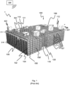
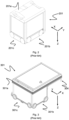
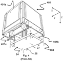
- Fig. 1 discloses a prior art automated storage and retrieval system 1 with a framework structure 100 and Figs. 2, 3 and 4 disclose three different prior art container handling vehicles 201,301,401 suitable for operating on such a system 1.
- the framework structure 100 comprises upright members 102 and a storage volume comprising storage columns 105 arranged in rows between the upright members 102.
- storage columns 105 storage containers 106, also known as bins, are stacked one on top of one another to form stacks 107.
- the members 102 may typically be made of metal, e.g. extruded aluminum profiles.
- the framework structure 100 of the automated storage and retrieval system 1 comprises a rail system 108 arranged across the top of framework structure 100, on which rail system 108 a plurality of container handling vehicles 201,301,401 may be operated to raise storage containers 106 from, and lower storage containers 106 into, the storage columns 105, and also to transport the storage containers 106 above the storage columns 105.
- the rail system 108 comprises a first set of parallel rails 110 arranged to guide movement of the container handling vehicles 201,301,401 in a first direction X across the top of the frame structure 100, and a second set of parallel rails 111 arranged perpendicular to the first set of parallel rails 110 to guide movement of the container handling vehicles 201,301,401 in a second direction Y which is perpendicular to the first direction X.
- Containers 106 stored in the columns 105 are accessed by the container handling vehicles 201,301,401 through access openings 112 in the rail system 108.
- the container handling vehicles 201,301,401 can move laterally above the storage columns 105, i.e. in a plane which is parallel to the horizontal X-Y plane.
- the upright members 102 of the framework structure 100 may be used to guide the storage containers during raising of the containers out from and lowering of the containers into the columns 105.
- the stacks 107 of containers 106 are typically self-supporting.
- Each prior art container handling vehicle 201,301,401 comprises a vehicle body 201a,301a,401a and first and second sets of wheels 201b,201c,301b,301c,401b,401c which enable the lateral movement of the container handling vehicles 201,301,401 in the X direction and in the Y direction, respectively.
- the first set of wheels 201b,301b,401b is arranged to engage with two adjacent rails of the first set of parallel rails 110
- the second set of wheels 201c,301c,401c is arranged to engage with two adjacent rails of the second set of parallel rails 111.
- At least one of the sets of wheels 201b,201c,301b,301c,401b,401c can be lifted and lowered, so that the first set of wheels 201b,301b,401b and/or the second set of wheels 201c,301c,401c can be engaged with the respective set of parallel rails 110, 111 at any one time.
- Each prior art container handling vehicle 201,301,401 also comprises a lifting device for vertical transportation of storage containers 106, e.g. raising a storage container 106 from, and lowering a storage container 106 into, a storage column 105.
- the lifting device comprises one or more gripping / engaging devices which are adapted to engage a storage container 106, and which gripping / engaging devices can be lowered from the vehicle 201,301,401 so that the position of the gripping / engaging devices with respect to the vehicle 201,301,401 can be adjusted in a third direction Z which is orthogonal the first direction X and the second direction Y.
- Parts of the gripping device of the container handling vehicles 301,401 are shown in Figs. 3 and 4 indicated with reference number 304,404.
- the gripping device of the container handling device 201 is located within the vehicle body 201a in Fig. 2 and is thus not shown.
- the lifting device may comprise a lifting frame 27 suspended from lifting bands 25.
- the lifting bands 25 may provide power and communication between the container handling vehicle and the lifting frame 27.
- the lifting frame 27 may comprise gripping engaging devices 26 for connection to gripping recesses of a storage container 106.
- the storage volume of the framework structure 100 has often been referred to as a grid 104, where the possible storage positions within this grid are referred to as storage cells.
- Each storage column may be identified by a position in an X- and Y- direction, while each storage cell may be identified by a container number in the X -, Y- and Z -direction.
- Each prior art container handling vehicle 201,301,401 comprises a storage compartment or space for receiving and stowing a storage container 106 when transporting the storage container 106 across the rail system 108.
- the storage space may comprise a cavity arranged internally within the vehicle body 201a,401a as shown in Figs. 2 and 4 and as described in e.g. WO2015/193278A1 and WO2019/206487A1 , the contents of which are incorporated herein by reference.
- Fig. 3 shows an alternative configuration of a container handling vehicle 301 with a cantilever construction.
- a container handling vehicle 301 with a cantilever construction.
- Such a vehicle is described in detail in e.g. NO317366, the contents of which are also incorporated herein by reference.
- the cavity container handling vehicle 201 shown in Fig. 2 may have a footprint that covers an area with dimensions in the X and Y directions which is generally equal to the lateral extent of a storage column 105, e.g. as is described in WO2015/193278A1 , the contents of which are incorporated herein by reference.
- the term ⁇ lateral' used herein may mean 'horizontal'.
- the cavity container handling vehicles 401 may have a footprint which is larger than the lateral area defined by a storage column 105 as shown in Fig. 1 and 4 , e.g. as is disclosed in WO2014/090684A1 or WO2019/206487A1 .
- the rail system 108 typically comprises rails with grooves in which the wheels of the vehicles run.
- the rails may comprise upwardly protruding elements, where the wheels of the vehicles comprise flanges to prevent derailing. These grooves and upwardly protruding elements are collectively known as tracks.
- Each rail may comprise one track, or each rail 110,111 may comprise two parallel tracks.
- each rail in one direction e.g. an X direction
- each rail in the other, perpendicular direction e.g. a Y direction
- Each rail 110,111 may also comprise two track members that are fastened together, each track member providing one of a pair of tracks provided by each rail.
- WO2018/146304A1 illustrates a typical configuration of rail system 108 comprising rails and parallel tracks in both X and Y directions.
- columns 105 In the framework structure 100, a majority of the columns 105 are storage columns 105, i.e. columns 105 where storage containers 106 are stored in stacks 107. However, some columns 105 may have other purposes.
- columns 119 and 120 are such special-purpose columns used by the container handling vehicles 201,301,401 to drop off and/or pick up storage containers 106 so that they can be transported to an access station (not shown) where the storage containers 106 can be accessed from outside of the framework structure 100 or transferred out of or into the framework structure 100.
- such a location is normally referred to as a 'port' and the column in which the port is located may be referred to as a ⁇ port column' 119,120.
- the transportation to the access station may be in any direction, that is horizontal, tilted and/or vertical.
- the storage containers 106 may be placed in a random or dedicated column 105 within the framework structure 100, then picked up by any container handling vehicle and transported to a port column 119,120 for further transportation to an access station.
- the transportation from the port to the access station may require movement along various different directions, by means such as delivery vehicles, trolleys or other transportation lines.
- the term 'tilted' means transportation of storage containers 106 having a general transportation orientation somewhere between horizontal and vertical.
- the first port column 119 may for example be a dedicated drop-off port column where the container handling vehicles 201,301,401 can drop off storage containers 106 to be transported to an access or a transfer station
- the second port column 120 may be a dedicated pick-up port column where the container handling vehicles 201,301,401 can pick up storage containers 106 that have been transported from an access or a transfer station.
- the access station may typically be a picking or a stocking station where product items are removed from or positioned into the storage containers 106.
- the storage containers 106 are normally not removed from the automated storage and retrieval system 1, but are returned into the framework structure 100 again once accessed.
- a port can also be used for transferring storage containers to another storage facility (e.g. to another framework structure or to another automated storage and retrieval system), to a transport vehicle (e.g. a train or a lorry), or to a production facility.
- a conveyor system comprising conveyors is normally employed to transport the storage containers between the port columns 119,120 and the access station.
- the conveyor system may comprise a lift device with a vertical component for transporting the storage containers 106 vertically between the port column 119,120 and the access station.
- the conveyor system may be arranged to transfer storage containers 106 between different framework structures, e.g. as is described in WO2014/075937A1 , the contents of which are incorporated herein by reference.
- one of the container handling vehicles 201,301,401 is instructed to pick up the storage container 106 from the pick-up port column 120 and transport it to a location above the storage column 105 where it is to be stored.
- the container handling vehicle 201,301,401 positions the storage container 106 at the desired position. The removed storage containers 106 may then be lowered back into the storage column 105, or relocated to other storage columns 105.
- the automated storage and retrieval system 1 For monitoring and controlling the automated storage and retrieval system 1, e.g. monitoring and controlling the location of respective storage containers 106 within the framework structure 100, the content of each storage container 106; and the movement of the container handling vehicles 201,301,401 so that a desired storage container 106 can be delivered to the desired location at the desired time without the container handling vehicles 201,301,401 colliding with each other, the automated storage and retrieval system 1 comprises a control system 500 which typically is computerized and which typically comprises a database for keeping track of the storage containers 106.
- WO 2020/074257 A1 (AutoStore AS) relates to an expansion joint which allows relative movement in the longitudinal direction.
- the longitudinal extension in the thermal expansion joint is between two crossings.
- a container handling vehicle enters an X-Y crossing, there are no sidewalls, thus the light is not reflected back to the sensor. This effect can be used to determine the position of a container handling vehicle.
- the expander joint has a part without side walls, false signals can result.
- Software in the vehicle can correct for any such false signal of the rail/track sensor in the container handling vehicles when driving over an expander joint, possibly in connection with measurement of cell size (the size of the cells with expander joints are not fixed as is the case for fixed grid cells).
- the control system keeps track of all vehicles in the system and knows when the vehicle is about to enter a cell with an expansion joint.
- the overall control system may then either ignore the signal representing the false signal at the expansion joint or, turn off the sensor in the vehicle when passing the expansion joint.
- the risk of such false signals may be reduced by arranging a sliding sidewall at the expansion joint which moves together with the expansion joint or which is of such a size that it covers the expansion joint also in a maximum extended position.
- One objective of the invention is to solve at least some of the drawbacks related to prior art solutions.
- both the first and the second rails may be provided as a pair of rail sections arranged in an end-to-end manner in the longitudinal direction of said rail, the ends of the rail sections meeting in a central portion of the crossing and the rail sections being configured to permit a range of movement of one end relative to the other in the longitudinal direction of the said rail.
- the crossing can provide a thermal expansion joint for both the first and the second rails within the volume of the crossing defined by the engagement of the first and second rails.
- the profiles of the crossing may be arranged to form one or more expansion gaps as the rails contract and expand the expansion j oint, these expansion gaps being located within the crossing defined by the engagement of the first and second rails.
- At least a majority of, if not all, of the longitudinal expansion and retraction of the thermal expansion joint is within the volume defined by the engagement of the first and second rails.
- At least one of the rail sections of the said rail may comprise a cutout on a lower portion thereof, wherein the cutout extends in a longitudinal direction of the rail section for receiving an upper edge of the upright member such that the rail section can move in a longitudinal direction relative the upper edge of the upright member.
- cutouts on both or only one side of the crossing.
- the cutouts are of such a size that the upper edge of the upright member can move "freely” therein, thus avoiding a risk that the upright member could be bent upon expansion or contraction of a rail connected to the upper edge of the upright member.
- the cutouts are smaller such that the upper edge of the upright member and the cutout form a tight fit therebetween with no room for relative movement of the rail section compared to the upright member.
- the crossing may comprise:
- one of the pair of rail sections may comprise the X top profile extending in the first direction X and the X bottom profile extending in the first direction X.
- the other of the pair of rail sections may also comprise a X top profile extending in the first direction X and a X bottom profile extending in the first direction X.
- the profiles of the first and second direction X,Y may define a hollow where the tracks of the rails cross one another.
- the crossing may be provided with a horizontal member, or a set of horizontal members, that can slide with respect to at least one of the rail sections in the hollow as the thermal expansion joint expands and contracts.
- the horizontal member(s) may have an upper surface which provides a continuation of a rolling surface of the tracks across the thermal expansion joint.
- a lower surface of the horizontal member(s) may be arranged to slide on a surface of the hollow between the rail sections or on another of the horizontal members during expansion and contraction of the rail(s). Expansion gaps may form on opposite sides of the horizontal member as the rail contracts and the expansion joint expands, or on only one side, depending on whether the horizontal member is tethered to one of the rail sections.
- one of the first portions is arranged on one side of the second portion and the other first portion is arranged on the other side of the second portion, and wherein the X top profile comprises a groove for accommodating one of the first portions of the splice piece.
- the X top profile comprises two lip portions and an opening in between the two lip portions, wherein the opening is formed in an extension of the groove and is configured to receive one of the first portions and a part of the second portion of the splice piece, and wherein, when the first portion of the splice piece is positioned in the groove, an upper surface of the second portion is flush with a rolling surface of the track of a rail of the first rail.
- the X bottom profile comprises an upper end face and a lower end face, and wherein a receiving space formed between two opposing upper end faces of the X bottom profile is larger than a volume occupied by a perpendicular Y profile extending in the second direction such that at least one of the X bottom profiles can move in the first direction relative to a side surface of the perpendicular Y profile.
- the X bottom profile comprises a hollow portion and wherein the crossing comprises a reinforcement bar having a first end and a second end, and wherein the first end is connectable within the hollow portion and the second end of the reinforcement bar extends out of the hollow portion and is configured to extend into a hollow portion of an opposing X bottom profile.
- the second end of the reinforcement bar is not secured to the hollow portion of the opposing X bottom profile but rather arranged to slide inside the hollow portion of the opposing X bottom profile.
- a thickness of the connection piece is chosen such that, when connected, a top surface of the connection piece is flush with a rolling surface of the track of a rail of the second rail.
- an upper end of the lower end face comprises a recess with a larger extent in the second direction than width in the second direction of a protruding rim of the X bottom profile, such that when the protruding rim is positioned within the recess, the Y profile can move relative the protruding rim.
- the Y profile according to the second embodiment of the invention can move relative the perpendicular X bottom profile.
- a lower receiving space formed between two opposing lower end faces of the Y profile is larger than a volume occupied by a perpendicular X bottom profile extending in the first direction X such that at least one of the Y bottom profiles can move in the second direction Y relative to a side surface of the perpendicular X bottom profile.
- the Y profile comprises a hollow portion and wherein the crossing comprises a reinforcement bar having a first end and a second end, and wherein the first end is connectable within the hollow portion and the second end of the reinforcement bar extends out of the hollow portion and is configured to extend into a hollow portion of an opposing Y profile.
- the thermal expansion joint comprises a splice piece having a first portion of a first thickness and a second portion of the same first thickness, and an intermediate portion with a second thickness arranged between the first and second portions.
- the X top profile comprises a groove for receiving the first portion of the splice piece such that the first portion can be accommodated in the groove.
- the first portion comprises connection portions complementary shaped as connection holes of the X top profile such that the splice piece can be secured to the X top profile.
- the second thickness of the intermediate portion is selected such that an upper surface of the intermediate portion is flush with a rolling surface of the track of a rail of the first rail of the X top profiles when the first portion of the splice piece is positioned in the groove of the X top profile.
- the second portion of the splice piece is formed as a lip.
- the two protruding members have a thickness equal to the first thickness while the remaining part of the intermediate section is of the second thickness.
- the thermal expansion joint features two cradle pieces, wherein the cradle pieces feature connection holes for connection to complementary holes of an underlying Y profile.
- the cradle pieces feature a first portion having the second thickness and a second portion having the second thickness, and an intermediate portion of the first thickness.
- the intermediate portion is shaped such that the protruding member of the splice piece is allowed to slide therein upon expansion and retraction of the first rail or the second rail.
- a storage system comprising a framework structure, the framework structure comprising upright members and a two-dimensional rail system arranged across the top of the upright members, the rail system comprises a first set of parallel rails arranged to guide movement of container handling vehicles in a first direction X across the top of the frame structure, and a second set of parallel rails arranged perpendicular to the first set of rails to guide movement of the container handling vehicles in a second direction Y which is perpendicular to the first direction, the first and second sets of parallel rails dividing the rail system into a plurality of access openings in the rail system for lifting and lowering of a storage container between a position above the rail system and a position below the rail system, and wherein the storage system comprises at least one crossing as defined above arranged along each rail of the of first or second set of parallel rails forming a continuous track from one end of the rail system to an opposite end of the rail system.
- a set of parallel rails comprises two rails in the same direction with a distance therebetween.
- both of the rails in the set of parallel rails has at least one crossing each.
- the above described crossings may be interspersed though the two-dimensional rail system (grid-based rail system), for example, every 2, 3, 4, 5 or other number of conventional crossings without a thermal expansion joint. Depending on the proportions of the spaces in the framework structure, the above described crossings may be provided more frequently at the crossings in one direction compared to the other direction.
- the crossing may be arranged to lie within a vertical proj ection of a hollow center section of an upright member when supported by the upright members.
- the crossings according to the three described embodiments are preferably connectable to the prior art first and second set of parallel rails. There may be one or more crossings along one length of rail, dependent on the expected temperature variations and thus expansion and contraction of the rails. Therefore, one length of rail, i.e. one rail extending from one end of the rail system to the other end of the rail system typically comprises a plurality of standard prior art crossings and one or more of the crossings according to the three described embodiments.
- a framework structure 100 of the automated storage and retrieval system 1 may be constructed in a similar manner to the prior art framework structure 100 described above in connection with Figs. 1 . That is, the framework structure 100 may comprise a number of upright members 102, and comprise a first, upper rail system 108 extending in the X direction and Y direction.
- the framework structure 100 may further comprise storage compartments in the form of storage columns 105 provided between the members 102 wherein storage containers 106 may be stackable in stacks 107 within the storage columns 105.
- the framework structure 100 can be of any size. In particular, it is understood that the framework structure can be considerably wider and/or longer and/or deeper than disclosed in Fig. 1 .
- the framework structure 100 may have a horizontal extent of more than 700x700 columns and a storage depth of more than twelve containers.
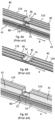
- Fig. 5A is a side perspective view of part of a prior art rail system 108 with crossing 30 between a first set of parallel rails 110 comprising X top profiles 40 and X bottom profiles 41, wherein the first set of parallel rails 110 extends in a first direction X, and a second set of parallel rails 111 comprising Y profiles 42, wherein the second set of parallel rails 111 extends in a second direction Y which is perpendicular to the first direction X.
- the rail system 108 is supported on top of an upright member 102 at the crossing 30.
- the X bottom profiles 41 each comprise cutouts 73 for receiving an upper edge 103 (just visible in Fig. 5A , but see also Fig.
- a receiving space 80 is formed for accommodating a Y profile 42 which extends in a perpendicular direction therein.
- the Y profile 42 is provided with a similar receiving space 81 on an underside thereof (not illustrated in Fig. 5A , see details in e.g. Figs. 11A and 11B ) for accommodating the X bottom profiles 41.
- the X top profile 40 is positioned on top of the X bottom profile 41.
- the crossing 30 formed by the first set of parallel rails 110 and the second set of parallel rails 111 thus do not provide any flexibility in terms of longitudinal expansion and contraction in any of the first direction X or the second direction Y.
- the lip portions 74 of the X top profiles 40 are in contact with each other.
- the lip portions 74 have a flat upper surface such that vehicles (not shown in Fig. 5A , but see Figs. 2, 3 and 4 ) driving in both the first direction X and the second direction Y can pass over the crossing 30 unhindered.
- the crossings according to the three described embodiments are preferably connectable to rails of the prior art first and second set of parallel rails 110,111 and can be integrated within such rail systems, e.g., mixed with the prior art crossings.
- length of the rail is referring to the extent of the rail as a whole across the framework structure rather the sections of rail that might make a full rail.
- the rail may include breaks at unit intervals, expansion joints like those described in WO 2020/074257 , or other forms of expansion joint like that described herein, along a given length. Therefore, one length of rail, i.e. one rail extending from one end of the rail system 108 to the other end of the rail system 108 typically comprises a plurality of standard prior art crossings and one or more of the crossings according to, for example, one of the three described embodiments.
- Fig. 5B is a top view of the cross section of a prior art upright member 102.
- the upright member 102 comprises an inwardly facing surface (i.e. the corner 117) in the area of the upright member where the lifting frames are guided.
- the upright member 102 comprises vertical guide surfaces 116 (or vertical guide plates) for guiding a storage container being moved inside a storage column 105.
- each of the four upright members 102 provides an inside corner 117 for guiding a corresponding corner of a storage container 106.
- each upright member 102 features eight vertical guide surfaces 116 and may thus provide an inside corner 117 of four separate storage columns 112 of the storage grid 104.
- the upright member 102 comprises a hollow center section 113 (represented by dashed area 113 in Fig. 5B ) delimited by the upper edges 103 on four sides of the hollow center section 113.
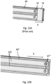
- Fig. 6A shows a prior art first set of parallel rails 110 comprising X top profiles 40 and X bottom profiles 41 extending in a first direction X.
- the two X top profiles 40 are arranged in contact with each other (end-to-end contact).
- the two X bottom profiles 41 are also in contact with each other (also end-to-end contact), and a receiving space 80 is formed between the X bottom profiles 41.
- Fig. 6B shows details of a connection between two prior art X top profiles 40.
- the top profile 40 displays two parallel tracks, i.e. so-called double tracks, such that one vehicle having one set of wheels in one of the tracks can pass adjacent another vehicle having one set of wheels in the other track.
- Fig. 6C shows details of a connection between two prior art X bottom profiles 41.
- the first rail 130 is provided as a pair of rail sections 130',130" arranged in an end-to-end manner in the longitudinal direction of said first rail 130.
- Rail section 130' comprises an X top profile 40' according to the first embodiment of the invention and a prior art X bottom profile 41.
- Rail section 130" on the opposite side of the crossing 30' comprises an X top profile 40' according to the first embodiment of the invention and an X bottom profile 41' according to the first embodiment of the invention.
- Fig. 7A shows details of one prior art X top profile 40.
- the X top profile 40 features a lip 74 which has a size equal to half of the width of a crossing 30 such that when connected to another lip 74 of another prior art X top profile 40, the two lips 74 form the crossing 30.
- Fig. 7B shows details of rail section 130' of a first rail 130 extending in the first direction X. It is shown a X top profile 40' according to a first embodiment of the invention.
- the X top profile 40' features a first set of parallel tracks 125 in the first direction X.
- connection holes 47 are provided in the first set of parallel tracks 125 for connecting the X top profile 40' to an underlying X bottom profile (underlying X bottom profile not shown in Fig. 7B , see e.g. Fig. 8B ) by suitable fastening means, such as screws or bolts, which is known to the skilled person.
- the X top profile 40' further comprises an opening 48 in between two lip portions 74' for receiving a splice piece 43' (see Figs. 7C and 7D ).
- the opening 48 has a width W2 which is equal to or somewhat larger than a width W1 of the splice piece 43'.
- the second thickness H2 of the second portion 45 is selected such that an upper surface of the second portion 45 is flush with a rolling surface of the first set of parallel tracks 125 of the X top profiles 40' when the first portion 44 of the splice piece 43' is positioned in the groove 46 of the X top profile 40'.
- the opening 48 has a length L2.
- a length L1 of the second portion 45 may be equal to or somewhat smaller than a total length (L2+L2) of two openings 48, such that two X top profiles 40 can come into contact with each other in the lip portions 74' when the splice piece 43' is positioned therebetween.
- the splice piece 43', including the first portion 44 and the second portion 45 has the same width W1 along its whole length L3.
- Fig. 8A shows details of one prior art X bottom profile 41.
- the prior art X bottom profile comprises cutouts 73 for receiving the upper edge 103 of the upright member 102 (not shown in Fig. 8A , see Fig. 5B ).
- the prior art X bottom profile 41 features an upper end face 75 and a lower end face 76.
- the lower end face 76 is for contacting an opposing lower end face of another prior art X bottom profile 41 whereas the upper end face 75 is arranged for contacting a side surface of a perpendicular prior art Y profile (not shown in Fig. 8A , see e.g. Fig. 11B ) to be arranged in the receiving space 80 formed between two opposing upper end faces 75 of the prior art X bottom profile 41.
- Fig. 8B shows details of a X bottom profile 41' according to the first embodiment of the invention.
- the X bottom profile 41' features cutouts 73' with an increased width compared to the cutouts 73 of the prior art X bottom profile 41 in Fig. 8A .
- the increased width of the cutouts 73' enables the possibility that the X bottom profile 41' (and the fixedly connected X top profile 40' (see Fig. 7B ) can slide relative the upper edge 103 of the upright member 102 and avoids bending of the upright member 102 during expansion and contraction of the rails in the first direction X.
- the upper end face 75' and the lower end face 76 are cut/shorter relative to the upper and lower end faces 75,76 in Fig. 8A .
- a perpendicular Y profile arranged in the receiving space 80' will thus not be in contact with at least one of the upper end faces 75' because of the increased distance between the opposing upper end faces 75'.
- the lower end face 76' is cut shorter relative to the lower end face 76 in Fig. 8A .
- the lower end faces 76' of two opposing X bottom profiles 41' according to the first embodiment are not in contact when the thermal expansion joint 35' has expanded (e.g., when the rails in the X direction have contracted).
- a first end of a reinforcement bar 51' can be secured in a hollow portion 49' of one of the X bottom profiles 41' and a second end of the reinforcement bar 51' may extend out from the hollow portion 49' and into a hollow portion 49' (not shown) of an opposing X bottom profile 41,41'.
- the second end of the reinforcement bar 51' is not secured to the hollow portion of the opposing X bottom profile 41,41' but rather arranged to slide inside the hollow portion of the opposing X bottom profile 41,41'.
- Fig. 8C illustrates the differences between the prior art X bottom profile 41 and the X bottom profile 41' according to the first embodiment, where the dotted lines indicate differences of the X bottom profile 41' according to the first embodiment of the invention and the solid lines indicate the prior art X bottom profile 41.
- the relative positions of the dotted lines and the fully lines are only for illustrative purposes.
- Fig. 9A shows details of the first rail 130 comprising the X top profiles 40' and the X bottom profiles 41',41 according to the first embodiment of the invention, where the thermal expansion joint 35' has contracted in the X direction, for example, as a result of expansion in the first rails 130 in the X direction.
- the X bottom profile 41' of the rail section 130" on the right-hand side has a cutout 73' which is wider than the cutout 73 of the prior art X bottom profile 41 on the left hand side.
- the X top profiles 40' are in contact with each other and the prior art X bottom profile 41 and the X bottom profile 41' according to the first embodiment of the invention are in contact with each other.
- the first portions 44 of the splice piece 43' are accommodated in the grooves 46 of the opposing X top profiles 40' (details of first portions 44 and grooves 46 not shown in Fig, 9A , see e.g. Figs. 7B and 7C ).
- Fig. 9B shows details of the X top profile in Fig. 9A where the X bottom profiles, the Y profile and the upright member have been removed for illustrative purposes.
- Fig. 9C shows details of the X bottom profile in Fig. 9A where the X top profile, the Y profile and the upright member have been removed for illustrative purposes.
- a prior art X bottom profile 41 is shown to the left in Fig. 9C .
- This prior art X bottom profile 41 has cutouts 73 of relatively smaller with than the cutouts of the X bottom profile 41' according to the first embodiment of the invention.
- Fig. 10A shows details of the first rails 130 comprising the X top profiles 40' and the X bottom profiles 41',41 according to the first embodiment of the invention, where the thermal expansion joint 35' has expanded in the first direction X of the first rails (in the first direction X) for example as a result of contraction of the rails in the first direction X.
- Fig. 10B shows details of the X top profiles 40' in Fig. 10A where the X bottom profiles, the Y profile and the upright member have been removed for illustrative purposes.
- Fig. 10C shows details of the X bottom profiles 41',41 in Fig. 10A where the X top profiles, Y profile and the upright member have been removed for illustrative purposes.
- Fig. 10C there is a gap G between the X bottom profiles 41',41 illustrating that the thermal expansion joint 35' has expanded (e.g. as compared to Fig. 9C where the X bottom profiles 41',41 are in contact with each other), e.g., as a result of the rails in the X direction contracting.
- Fig. 11A is a side perspective view of the prior art rail system in Fig. 5A where the rail system has been rotated 90 degrees.
- Fig. 11A better illustrates the prior art Y profiles of the rail system.
- Fig. 11B shows details of a connection between two prior art Y profiles 42 of Fig. 11A where the prior art X top profile 40, the prior art X bottom profile 41 and the upright member 102 have been removed for illustrative purposes. Similar to the prior art X bottom profiles 41 (see e.g. Fig 8A ), the prior art Y profiles comprise cutouts 73 for receiving the upper edge 103 of the upright member 102.
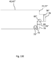
- the prior art Y profile 42 features an upper end face 77, an intermediate end face 78 and a lower end face 79.
- the upper end face 77 is for contacting a side surface of a perpendicular prior art X top profile 40 (not shown in Fig 11B , see e.g. Figs. 6B or 7A ) which is to be arranged in the upper receiving space 81 formed between two opposing upper end faces 77 of the prior art Y profiles 42.
- the lower end face 79 is for contacting a side surface of a perpendicular prior art X bottom profile 41 (not shown in Fig 11B , see e.g. Figs. 6C or 8A ) which is to be arranged in the lower receiving space 82 formed between two opposing lower end faces 79 of the prior art Y profiles 42.
- a recess 83 for locking prior art X bottom profile 41.
- Fig. 13B shows details of a Y profile 42" according to the second embodiment of the invention.
- connection piece 52 is disclosed as being made up of three elements 54,55,56 it is clear that the connection piece can be manufactured from one piece of raw material.
- the connection piece 52 features fastening holes 53 for connecting the connection piece 52 to complementary shaped holes 57 in the Y profile 42" using suitable fastening means such as screws or bolts which is known to the skilled person.
- the thickness H3 of the connection piece 52 is chosen such that, when connected, a top surface of the connection piece 52 is flush with a rolling surface of tracks 125 of the second rails 131.
- Fig. 13E illustrates the physical differences of the prior art Y profile and the Y profile 42" according to the second embodiment of the invention, where the dotted lines indicate the Y profile 42" according to the second embodiment of the invention and the solid lines indicate the prior art Y profile 42.
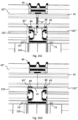
- Fig. 15A details of a crossing 30" of the second rails 131 comprising a Y profile 42" according to the second embodiment of the invention and one prior art Y profile 42, where the thermal expansion joint 35" has expanded in the second direction Y of the second rails 131, e.g. as a result of contraction of the rails in the second direction Y.
- Fig. 15B shows details of the Y profiles 42, 42" in Fig. 15A where the upright member 102 has also been removed for illustrative purposes.
- the reinforcement bar 51" is visible in between the Y profiles 42".
- Figs. 15A and 15B it can be seen that the first and second elements 55,56 of the first and second connection pieces 52, do not fully overlap with each other.
- Figs. 15A and 15B it can be clearly seen that the Y profiles 42, 42" have moved further away from each other (i.e. the Y profile 42" according to the second embodiment of the invention have contracted away from the fixed prior art Y profile 42 represented by expansion of the thermal expansion joint 35"). All of the required expansion in the crossing 30" for enabling the contraction of the Y profile 42" according to the second embodiment of the invention is taken up by the thermal expansion joint 35" within the crossing 30.
- Fig. 15C is a side view of Fig. 15A .
- Fig. 15D is a side view of Fig. 14A .
- a gap G is formed between the Y profile 42" according to the second embodiment of the invention and the prior art Y profile 42. This gap G is not visible in Fig. 15D .
- the protruding rim 84 of the X bottom profile 41 has moved to the left in Fig. 15D compared to Fig. 15C .
- the first rail 130 is provided as a pair of rail sections 130',130" arranged in an end-to-end manner in the longitudinal direction of said first rail 130.
- Rail section 130' of the first rail 130 comprises an X top profile 40′′′ according to the third embodiment of the invention and an X bottom profile 41' according to the first embodiment of the invention.
- Rail section 130" of the first rail 130 on the opposite side of the crossing 30' comprises an X top profile 40" according to the second embodiment of the invention and a prior art X bottom profile 41.
- the second rail 131 is provided as a pair of rail sections 131', 131" arranged in an end-to-end manner in the longitudinal direction of said second rail 131.
- Rail section 131' of the second rail 131 comprises a Y profile 42" according to the second embodiment of the invention.
- Rail section 131" of the second rail 131 on the opposite side of the crossing 30 comprises a prior art Y profile 42.
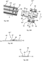
- Fig. 16A is a side perspective view of a X top profile 40′′′ according to a third embodiment of the invention.
- a corner 70 at the end of the X top profile 40′′′ closest to the crossing 30 has been cut or removed in order to make space for a perpendicular Y profile (not shown in Fig. 16A ) when the thermal expansion joint 35'" (see Fig. 16B ) has contracted.
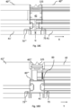
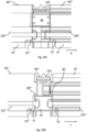
- Fig. 16B shows a third embodiment of the invention, and is an exploded view of the components forming part of the thermal expansion joint 35′′′, where the thermal expansion joint 35'" permits longitudinal extension in both a first direction X and a second direction Y.
- Fig. 16C is a side view of a splice piece 43′′′ of the thermal expansion joint 35'" in Fig. 16B .
- Fig. 16D is a side view of a cradle piece 60 of the thermal expansion joint 35'" in Fig. 16B .
- the thermal expansion joint 35'" features a splice piece 43'".
- the splice piece 43′′′ features a first portion 65 of a first thickness H1 and a second portion 66 of the same first thickness H1, the first and second portions 65,66 being arranged on opposite sides of an intermediate portion 67 with a greater second thickness H2.
- the first thickness H1 of the first portion 65 is somewhat smaller than a groove 46 in the X top profile 40′′′ such that the first portion 65 can be accommodated in the groove 46.
- the second portion 66 is also somewhat smaller than the groove 46 in the X top profile 40" (not shown in Figs. 16A-16D ) such that the second portion 66 can be accommodated in the groove 46.
- the first portion 65 comprises connection portions 68 complementary shaped as the connection holes 47′′′ of the X top profile 40′′′ such that the splice piece 43′′′ can be secured to the X top profile 40'".
- the second thickness H2 of the intermediate portion 67 is selected such that an upper surface of the intermediate portion 67 is flush with a rolling surface of the tracks 125 of the first rails 130 of the X top profiles 40′′′ when the first portion 65 of the splice piece 43′′′ is positioned in the groove 46 of the X top profile 40'".
- the second portion 66 of the splice piece 43′′′ is formed as a lip which can extend into a groove 46 of the X top profile 40" (not shown in Figs. 16A-16D ) as discussed above.
- the intermediate portion 67 of the splice piece 43′′′ is formed as a cross with two protruding members 69 extends perpendicular (in the second direction Y in Figs. 16A-16D ) relative a longitudinal direction of the splice piece 43'".
- the two protruding members 69 have a thickness equal to the first thickness H1 while the remaining part of the intermediate portion 67 is of the second thickness H2.
- the thermal expansion joint 35'" features two cradle pieces 60.
- the cradle pieces 60 feature connection holes 64 for connection to complementary holes 57 of an underlying Y profile 42,42" (Y profile not shown in Figs. 16A-16D , see e.g. Fig. 17A ).
- the cradle piece 60 features a first portion 61 having the second thickness H2 and a second portion 62 having the second thickness H2, and an intermediate portion 63 of the first thickness H1.
- the intermediate portion 63 is shaped such that the protruding member 69 of the splice piece 43′′′ is allowed to slide therein. I.e., a length of the intermediate portion 63 is somewhat larger than the extent of the protruding member 69 in the longitudinal direction (i.e. in the first direction X) of the splice piece 43'".
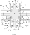
- Fig. 17A is a top view of the third embodiment of the invention, where the components in Figs. 16A-16D have been connected to respective X top profiles 40",40′′′ and Y profiles 42,42", and where the thermal expansion joint 35'" has contracted in both the first direction X and the second direction Y. e.g. as a result of expansion of the rails in the first direction X and in the second direction Y.
- the first rails 130 comprises rail sections 130',130" in the first direction X extends from below to above the crossing 30, whereas the second rail 131 comprises rail sections 131',131" in the second direction Y extending from left to right-hand side of the crossing 30.
- the rail section 130' below the crossing 30 is supported on a X bottom profile 41' similar to the X bottom profile 41' according to the first embodiment of the invention and X top profile 40′′′ according to a third embodiment of the invention where a corner 70 at the end of the X top profile 40′′′ closest to the crossing 30 has been cut or removed in order to make space for a perpendicular Y profile 42".
- the splice piece 43′′′ is connected to the X top profile 40′′′ (and connected to the X bottom profile 41') of the rail section 130'.
- the X bottom profile 41', the X top profile 40′′′ and the splice piece 43′′′ of rail section 130' are configured to move relative the opposing rail section 130" on the opposite side of the crossing 30 (similar to the function in the first embodiment of the invention).
- the rail section 130" above the crossing 30 is supported on a prior art X bottom profile 41 and a X top profile 40" similar to the X top profile 40" according to the second embodiment of the invention where the lip portion has been cut off such that the X top profile 40" does not extend into the crossing 30.
- the prior art X bottom profile 41 and X top profile 40" are stationary, but the X top profile 40" allows the second portion 66 of the splice piece to move within the groove 46 (not shown).
- Fig. 17C is a top view of the third embodiment of the invention, where the thermal expansion joint 35'" has expanded both in the first direction X and in the second direction Y, e.g. as a result of contraction of the rails in the first direction X and in the second direction Y.
- the disclosure comprises the following items:
Landscapes
- Engineering & Computer Science (AREA)
- Mechanical Engineering (AREA)
- Architecture (AREA)
- Civil Engineering (AREA)
- Structural Engineering (AREA)
- Physics & Mathematics (AREA)
- Mathematical Physics (AREA)
- Warehouses Or Storage Devices (AREA)
- Container, Conveyance, Adherence, Positioning, Of Wafer (AREA)
- Machines For Laying And Maintaining Railways (AREA)
- Monitoring And Testing Of Nuclear Reactors (AREA)
- Manipulator (AREA)
Applications Claiming Priority (3)
| Application Number | Priority Date | Filing Date | Title |
|---|---|---|---|
| NO20211521A NO20211521A1 (en) | 2021-12-16 | 2021-12-16 | Crossing with thermal expansion joint for a rail-based grid and method providing a crossing |
| PCT/EP2022/085086 WO2023110649A1 (en) | 2021-12-16 | 2022-12-09 | Crossing with thermal expansion joint for a rail-based grid |
| EP22835277.9A EP4448419A1 (de) | 2021-12-16 | 2022-12-09 | Kreuzung mit wärmeausdehnungsfuge für ein schienenbasiertes gitter |
Related Parent Applications (1)
| Application Number | Title | Priority Date | Filing Date |
|---|---|---|---|
| EP22835277.9A Division EP4448419A1 (de) | 2021-12-16 | 2022-12-09 | Kreuzung mit wärmeausdehnungsfuge für ein schienenbasiertes gitter |
Publications (2)
| Publication Number | Publication Date |
|---|---|
| EP4528028A2 true EP4528028A2 (de) | 2025-03-26 |
| EP4528028A3 EP4528028A3 (de) | 2025-06-04 |
Family
ID=84785196
Family Applications (2)
| Application Number | Title | Priority Date | Filing Date |
|---|---|---|---|
| EP22835277.9A Pending EP4448419A1 (de) | 2021-12-16 | 2022-12-09 | Kreuzung mit wärmeausdehnungsfuge für ein schienenbasiertes gitter |
| EP25155901.9A Withdrawn EP4528028A3 (de) | 2021-12-16 | 2022-12-09 | Kreuzung mit wärmeausdehnungsfuge für ein schienenbasiertes gitter |
Family Applications Before (1)
| Application Number | Title | Priority Date | Filing Date |
|---|---|---|---|
| EP22835277.9A Pending EP4448419A1 (de) | 2021-12-16 | 2022-12-09 | Kreuzung mit wärmeausdehnungsfuge für ein schienenbasiertes gitter |
Country Status (9)
| Country | Link |
|---|---|
| US (1) | US20250034817A1 (de) |
| EP (2) | EP4448419A1 (de) |
| JP (1) | JP2025500166A (de) |
| KR (1) | KR20240121297A (de) |
| CN (1) | CN118414289A (de) |
| CA (1) | CA3237518A1 (de) |
| NO (1) | NO20211521A1 (de) |
| TW (1) | TW202344452A (de) |
| WO (1) | WO2023110649A1 (de) |
Citations (9)
| Publication number | Priority date | Publication date | Assignee | Title |
|---|---|---|---|---|
| NO317366B1 (no) | 1999-07-01 | 2004-10-18 | Autostore As | Lagringsanlegg med fjernstyrte vogner med to hjulsett og heisinnretning for drift på skinner anlagt i kryss over kolonner av lagringsenheter som er adskilt med vertikale profilstolper |
| WO2014075937A1 (en) | 2012-11-13 | 2014-05-22 | Jakob Hatteland Logistics As | Storage system |
| WO2014090684A1 (en) | 2012-12-10 | 2014-06-19 | Jakob Hatteland Logistics As | Robot for transporting storage bins |
| WO2015193278A1 (en) | 2014-06-19 | 2015-12-23 | Jakob Hatteland Logistics As | Robot for transporting storage bins |
| WO2018146304A1 (en) | 2017-02-13 | 2018-08-16 | Autostore Technology AS | Rail arrangement for a storage system |
| WO2019206487A1 (en) | 2018-04-25 | 2019-10-31 | Autostore Technology AS | Container handling vehicle with first and second sections and lifting device motor in second section |
| WO2019238694A1 (en) | 2018-06-12 | 2019-12-19 | Autostore Technology AS | Storage system |
| WO2019238697A1 (en) | 2018-06-12 | 2019-12-19 | Autostore Technology AS | Automated storage system |
| WO2020074257A1 (en) | 2018-10-09 | 2020-04-16 | Autostore Technology AS | Expansion joint, system and method for connecting regions of a rail-based grid storage system |
Family Cites Families (4)
| Publication number | Priority date | Publication date | Assignee | Title |
|---|---|---|---|---|
| US3951365A (en) * | 1973-02-26 | 1976-04-20 | Mitsui Shipbuilding & Engineering Co., Ltd. | Rail crossover arrangement |
| JPS6189001U (de) * | 1984-11-16 | 1986-06-10 | ||
| FR3007430B1 (fr) * | 2013-06-25 | 2015-06-19 | Newtl | Croisement de rails prevu pour le croisement d'un rail de guidage avec un second rail. |
| KR102330832B1 (ko) * | 2020-05-12 | 2021-11-25 | (주)신세계엔지니어링 | 레일유닛의 조립성 및 설치 편의성을 향상시킨 팔레트 이송장치 |
-
2021
- 2021-12-16 NO NO20211521A patent/NO20211521A1/en unknown
-
2022
- 2022-12-05 TW TW111146546A patent/TW202344452A/zh unknown
- 2022-12-09 CA CA3237518A patent/CA3237518A1/en active Pending
- 2022-12-09 EP EP22835277.9A patent/EP4448419A1/de active Pending
- 2022-12-09 JP JP2024534256A patent/JP2025500166A/ja active Pending
- 2022-12-09 KR KR1020247023213A patent/KR20240121297A/ko active Pending
- 2022-12-09 CN CN202280083370.9A patent/CN118414289A/zh active Pending
- 2022-12-09 WO PCT/EP2022/085086 patent/WO2023110649A1/en not_active Ceased
- 2022-12-09 EP EP25155901.9A patent/EP4528028A3/de not_active Withdrawn
- 2022-12-09 US US18/715,656 patent/US20250034817A1/en active Pending
Patent Citations (9)
| Publication number | Priority date | Publication date | Assignee | Title |
|---|---|---|---|---|
| NO317366B1 (no) | 1999-07-01 | 2004-10-18 | Autostore As | Lagringsanlegg med fjernstyrte vogner med to hjulsett og heisinnretning for drift på skinner anlagt i kryss over kolonner av lagringsenheter som er adskilt med vertikale profilstolper |
| WO2014075937A1 (en) | 2012-11-13 | 2014-05-22 | Jakob Hatteland Logistics As | Storage system |
| WO2014090684A1 (en) | 2012-12-10 | 2014-06-19 | Jakob Hatteland Logistics As | Robot for transporting storage bins |
| WO2015193278A1 (en) | 2014-06-19 | 2015-12-23 | Jakob Hatteland Logistics As | Robot for transporting storage bins |
| WO2018146304A1 (en) | 2017-02-13 | 2018-08-16 | Autostore Technology AS | Rail arrangement for a storage system |
| WO2019206487A1 (en) | 2018-04-25 | 2019-10-31 | Autostore Technology AS | Container handling vehicle with first and second sections and lifting device motor in second section |
| WO2019238694A1 (en) | 2018-06-12 | 2019-12-19 | Autostore Technology AS | Storage system |
| WO2019238697A1 (en) | 2018-06-12 | 2019-12-19 | Autostore Technology AS | Automated storage system |
| WO2020074257A1 (en) | 2018-10-09 | 2020-04-16 | Autostore Technology AS | Expansion joint, system and method for connecting regions of a rail-based grid storage system |
Also Published As
| Publication number | Publication date |
|---|---|
| WO2023110649A1 (en) | 2023-06-22 |
| EP4448419A1 (de) | 2024-10-23 |
| JP2025500166A (ja) | 2025-01-09 |
| CA3237518A1 (en) | 2023-06-22 |
| US20250034817A1 (en) | 2025-01-30 |
| KR20240121297A (ko) | 2024-08-08 |
| NO20211521A1 (en) | 2023-06-19 |
| CN118414289A (zh) | 2024-07-30 |
| TW202344452A (zh) | 2023-11-16 |
| EP4528028A3 (de) | 2025-06-04 |
Similar Documents
| Publication | Publication Date | Title |
|---|---|---|
| US20250011082A1 (en) | Lifting frame assembly with extendible and retractable guide members, container handling vehicle and storage system, and associated method | |
| JP7528071B2 (ja) | レールベースのグリッド保管システムの領域同士を接続するためのエキスパンションジョイント、システム、および方法 | |
| US12139336B2 (en) | Transport of container handling vehicles between storage grids of different heights | |
| US12606374B2 (en) | Automated storage tower with multiple rows | |
| EP4347437B1 (de) | Dehnungsfuge zum verbinden eines ersten bereichs und eines zweiten bereichs eines schienensystems | |
| CA3210107A1 (en) | An automated storage system | |
| US20250034817A1 (en) | Crossing with thermal expansion joint for a rail-based grid | |
| HK40121242A (en) | Crossing with thermal expansion joint for a rail‑based grid | |
| US20250091804A1 (en) | Storage System | |
| WO2024120840A2 (en) | Lift arrangement and method for moving a storage container in a multiframework storage system | |
| NO20220489A1 (en) | Conveyor access station for an automated storage and retrieval system and a method for using same | |
| WO2024236056A1 (en) | Storage system comprising stack storage columns and shelf storage columns, and associated method | |
| NO348585B1 (en) | Leveling foot method for spacing upright members of a framework structure | |
| WO2024200791A1 (en) | Storage system |
Legal Events
| Date | Code | Title | Description |
|---|---|---|---|
| PUAI | Public reference made under article 153(3) epc to a published international application that has entered the european phase |
Free format text: ORIGINAL CODE: 0009012 |
|
| STAA | Information on the status of an ep patent application or granted ep patent |
Free format text: STATUS: THE APPLICATION HAS BEEN PUBLISHED |
|
| AC | Divisional application: reference to earlier application |
Ref document number: 4448419 Country of ref document: EP Kind code of ref document: P |
|
| AK | Designated contracting states |
Kind code of ref document: A2 Designated state(s): AL AT BE BG CH CY CZ DE DK EE ES FI FR GB GR HR HU IE IS IT LI LT LU LV MC ME MK MT NL NO PL PT RO RS SE SI SK SM TR |
|
| REG | Reference to a national code |
Ref country code: DE Ref legal event code: R079 Free format text: PREVIOUS MAIN CLASS: E01B0025280000 Ipc: B65G0001040000 |
|
| PUAL | Search report despatched |
Free format text: ORIGINAL CODE: 0009013 |
|
| AK | Designated contracting states |
Kind code of ref document: A3 Designated state(s): AL AT BE BG CH CY CZ DE DK EE ES FI FR GB GR HR HU IE IS IT LI LT LU LV MC ME MK MT NL NO PL PT RO RS SE SI SK SM TR |
|
| RIC1 | Information provided on ipc code assigned before grant |
Ipc: E01B 11/32 20060101ALI20250425BHEP Ipc: E01B 25/28 20060101ALI20250425BHEP Ipc: E01B 11/24 20060101ALI20250425BHEP Ipc: B65G 1/04 20060101AFI20250425BHEP |
|
| REG | Reference to a national code |
Ref country code: HK Ref legal event code: DE Ref document number: 40121242 Country of ref document: HK |
|
| STAA | Information on the status of an ep patent application or granted ep patent |
Free format text: STATUS: THE APPLICATION IS DEEMED TO BE WITHDRAWN |
|
| RAP3 | Party data changed (applicant data changed or rights of an application transferred) |
Owner name: AUTOSTORE TECHNOLOGY AS |
|
| 18D | Application deemed to be withdrawn |
Effective date: 20251205 |