EP4527683A1 - Conveyor vehicle system and method for controlling conveyor vehicle - Google Patents
Conveyor vehicle system and method for controlling conveyor vehicle Download PDFInfo
- Publication number
- EP4527683A1 EP4527683A1 EP23803389.8A EP23803389A EP4527683A1 EP 4527683 A1 EP4527683 A1 EP 4527683A1 EP 23803389 A EP23803389 A EP 23803389A EP 4527683 A1 EP4527683 A1 EP 4527683A1
- Authority
- EP
- European Patent Office
- Prior art keywords
- transport
- charging
- transport vehicle
- transport vehicles
- threshold value
- Prior art date
- Legal status (The legal status is an assumption and is not a legal conclusion. Google has not performed a legal analysis and makes no representation as to the accuracy of the status listed.)
- Pending
Links
Images




Classifications
-
- H—ELECTRICITY
- H02—GENERATION; CONVERSION OR DISTRIBUTION OF ELECTRIC POWER
- H02J—ELECTRIC POWER NETWORKS; CIRCUIT ARRANGEMENTS OR SYSTEMS FOR SUPPLYING OR DISTRIBUTING ELECTRIC POWER; SYSTEMS FOR STORING ELECTRIC ENERGY
- H02J7/00—Circuit arrangements for charging or discharging batteries or for supplying loads from batteries
- H02J7/02—Circuit arrangements for charging or discharging batteries or for supplying loads from batteries for charging batteries from AC mains by converters
-
- B—PERFORMING OPERATIONS; TRANSPORTING
- B60—VEHICLES IN GENERAL
- B60L—PROPULSION OF ELECTRICALLY-PROPELLED VEHICLES; SUPPLYING ELECTRIC POWER FOR AUXILIARY EQUIPMENT OF ELECTRICALLY-PROPELLED VEHICLES; ELECTRODYNAMIC BRAKE SYSTEMS FOR VEHICLES IN GENERAL; MAGNETIC SUSPENSION OR LEVITATION FOR VEHICLES; MONITORING OPERATING VARIABLES OF ELECTRICALLY-PROPELLED VEHICLES; ELECTRIC SAFETY DEVICES FOR ELECTRICALLY-PROPELLED VEHICLES
- B60L53/00—Methods of charging batteries, specially adapted for electric vehicles; Charging stations or on-board charging equipment therefor; Exchange of energy storage elements in electric vehicles
- B60L53/10—Methods of charging batteries, specially adapted for electric vehicles; Charging stations or on-board charging equipment therefor; Exchange of energy storage elements in electric vehicles characterised by the energy transfer between the charging station and the vehicle
- B60L53/14—Conductive energy transfer
-
- B—PERFORMING OPERATIONS; TRANSPORTING
- B60—VEHICLES IN GENERAL
- B60L—PROPULSION OF ELECTRICALLY-PROPELLED VEHICLES; SUPPLYING ELECTRIC POWER FOR AUXILIARY EQUIPMENT OF ELECTRICALLY-PROPELLED VEHICLES; ELECTRODYNAMIC BRAKE SYSTEMS FOR VEHICLES IN GENERAL; MAGNETIC SUSPENSION OR LEVITATION FOR VEHICLES; MONITORING OPERATING VARIABLES OF ELECTRICALLY-PROPELLED VEHICLES; ELECTRIC SAFETY DEVICES FOR ELECTRICALLY-PROPELLED VEHICLES
- B60L50/00—Electric propulsion with power supplied within the vehicle
- B60L50/50—Electric propulsion with power supplied within the vehicle using propulsion power supplied by batteries or fuel cells
- B60L50/60—Electric propulsion with power supplied within the vehicle using propulsion power supplied by batteries or fuel cells using power supplied by batteries
-
- B—PERFORMING OPERATIONS; TRANSPORTING
- B60—VEHICLES IN GENERAL
- B60L—PROPULSION OF ELECTRICALLY-PROPELLED VEHICLES; SUPPLYING ELECTRIC POWER FOR AUXILIARY EQUIPMENT OF ELECTRICALLY-PROPELLED VEHICLES; ELECTRODYNAMIC BRAKE SYSTEMS FOR VEHICLES IN GENERAL; MAGNETIC SUSPENSION OR LEVITATION FOR VEHICLES; MONITORING OPERATING VARIABLES OF ELECTRICALLY-PROPELLED VEHICLES; ELECTRIC SAFETY DEVICES FOR ELECTRICALLY-PROPELLED VEHICLES
- B60L53/00—Methods of charging batteries, specially adapted for electric vehicles; Charging stations or on-board charging equipment therefor; Exchange of energy storage elements in electric vehicles
- B60L53/30—Constructional details of charging stations
- B60L53/32—Constructional details of charging stations by charging in short intervals along the itinerary, e.g. during short stops
-
- B—PERFORMING OPERATIONS; TRANSPORTING
- B60—VEHICLES IN GENERAL
- B60L—PROPULSION OF ELECTRICALLY-PROPELLED VEHICLES; SUPPLYING ELECTRIC POWER FOR AUXILIARY EQUIPMENT OF ELECTRICALLY-PROPELLED VEHICLES; ELECTRODYNAMIC BRAKE SYSTEMS FOR VEHICLES IN GENERAL; MAGNETIC SUSPENSION OR LEVITATION FOR VEHICLES; MONITORING OPERATING VARIABLES OF ELECTRICALLY-PROPELLED VEHICLES; ELECTRIC SAFETY DEVICES FOR ELECTRICALLY-PROPELLED VEHICLES
- B60L53/00—Methods of charging batteries, specially adapted for electric vehicles; Charging stations or on-board charging equipment therefor; Exchange of energy storage elements in electric vehicles
- B60L53/60—Monitoring or controlling charging stations
-
- B—PERFORMING OPERATIONS; TRANSPORTING
- B60—VEHICLES IN GENERAL
- B60L—PROPULSION OF ELECTRICALLY-PROPELLED VEHICLES; SUPPLYING ELECTRIC POWER FOR AUXILIARY EQUIPMENT OF ELECTRICALLY-PROPELLED VEHICLES; ELECTRODYNAMIC BRAKE SYSTEMS FOR VEHICLES IN GENERAL; MAGNETIC SUSPENSION OR LEVITATION FOR VEHICLES; MONITORING OPERATING VARIABLES OF ELECTRICALLY-PROPELLED VEHICLES; ELECTRIC SAFETY DEVICES FOR ELECTRICALLY-PROPELLED VEHICLES
- B60L53/00—Methods of charging batteries, specially adapted for electric vehicles; Charging stations or on-board charging equipment therefor; Exchange of energy storage elements in electric vehicles
- B60L53/60—Monitoring or controlling charging stations
- B60L53/62—Monitoring or controlling charging stations in response to charging parameters, e.g. current, voltage or electrical charge
-
- B—PERFORMING OPERATIONS; TRANSPORTING
- B60—VEHICLES IN GENERAL
- B60L—PROPULSION OF ELECTRICALLY-PROPELLED VEHICLES; SUPPLYING ELECTRIC POWER FOR AUXILIARY EQUIPMENT OF ELECTRICALLY-PROPELLED VEHICLES; ELECTRODYNAMIC BRAKE SYSTEMS FOR VEHICLES IN GENERAL; MAGNETIC SUSPENSION OR LEVITATION FOR VEHICLES; MONITORING OPERATING VARIABLES OF ELECTRICALLY-PROPELLED VEHICLES; ELECTRIC SAFETY DEVICES FOR ELECTRICALLY-PROPELLED VEHICLES
- B60L53/00—Methods of charging batteries, specially adapted for electric vehicles; Charging stations or on-board charging equipment therefor; Exchange of energy storage elements in electric vehicles
- B60L53/60—Monitoring or controlling charging stations
- B60L53/66—Data transfer between charging stations and vehicles
-
- B—PERFORMING OPERATIONS; TRANSPORTING
- B60—VEHICLES IN GENERAL
- B60L—PROPULSION OF ELECTRICALLY-PROPELLED VEHICLES; SUPPLYING ELECTRIC POWER FOR AUXILIARY EQUIPMENT OF ELECTRICALLY-PROPELLED VEHICLES; ELECTRODYNAMIC BRAKE SYSTEMS FOR VEHICLES IN GENERAL; MAGNETIC SUSPENSION OR LEVITATION FOR VEHICLES; MONITORING OPERATING VARIABLES OF ELECTRICALLY-PROPELLED VEHICLES; ELECTRIC SAFETY DEVICES FOR ELECTRICALLY-PROPELLED VEHICLES
- B60L53/00—Methods of charging batteries, specially adapted for electric vehicles; Charging stations or on-board charging equipment therefor; Exchange of energy storage elements in electric vehicles
- B60L53/60—Monitoring or controlling charging stations
- B60L53/67—Controlling two or more charging stations
-
- B—PERFORMING OPERATIONS; TRANSPORTING
- B60—VEHICLES IN GENERAL
- B60L—PROPULSION OF ELECTRICALLY-PROPELLED VEHICLES; SUPPLYING ELECTRIC POWER FOR AUXILIARY EQUIPMENT OF ELECTRICALLY-PROPELLED VEHICLES; ELECTRODYNAMIC BRAKE SYSTEMS FOR VEHICLES IN GENERAL; MAGNETIC SUSPENSION OR LEVITATION FOR VEHICLES; MONITORING OPERATING VARIABLES OF ELECTRICALLY-PROPELLED VEHICLES; ELECTRIC SAFETY DEVICES FOR ELECTRICALLY-PROPELLED VEHICLES
- B60L58/00—Methods or circuit arrangements for monitoring or controlling batteries or fuel cells, specially adapted for electric vehicles
- B60L58/10—Methods or circuit arrangements for monitoring or controlling batteries or fuel cells, specially adapted for electric vehicles for monitoring or controlling batteries
- B60L58/12—Methods or circuit arrangements for monitoring or controlling batteries or fuel cells, specially adapted for electric vehicles for monitoring or controlling batteries responding to state of charge [SoC]
-
- B—PERFORMING OPERATIONS; TRANSPORTING
- B60—VEHICLES IN GENERAL
- B60L—PROPULSION OF ELECTRICALLY-PROPELLED VEHICLES; SUPPLYING ELECTRIC POWER FOR AUXILIARY EQUIPMENT OF ELECTRICALLY-PROPELLED VEHICLES; ELECTRODYNAMIC BRAKE SYSTEMS FOR VEHICLES IN GENERAL; MAGNETIC SUSPENSION OR LEVITATION FOR VEHICLES; MONITORING OPERATING VARIABLES OF ELECTRICALLY-PROPELLED VEHICLES; ELECTRIC SAFETY DEVICES FOR ELECTRICALLY-PROPELLED VEHICLES
- B60L58/00—Methods or circuit arrangements for monitoring or controlling batteries or fuel cells, specially adapted for electric vehicles
- B60L58/10—Methods or circuit arrangements for monitoring or controlling batteries or fuel cells, specially adapted for electric vehicles for monitoring or controlling batteries
- B60L58/12—Methods or circuit arrangements for monitoring or controlling batteries or fuel cells, specially adapted for electric vehicles for monitoring or controlling batteries responding to state of charge [SoC]
- B60L58/14—Preventing excessive discharging
-
- B—PERFORMING OPERATIONS; TRANSPORTING
- B66—HOISTING; LIFTING; HAULING
- B66C—CRANES; LOAD-ENGAGING ELEMENTS OR DEVICES FOR CRANES, CAPSTANS, WINCHES, OR TACKLES
- B66C13/00—Other constructional features or details
- B66C13/18—Control systems or devices
- B66C13/48—Automatic control of crane drives for producing a single or repeated working cycle; Program control
-
- G—PHYSICS
- G05—CONTROLLING; REGULATING
- G05D—SYSTEMS FOR CONTROLLING OR REGULATING NON-ELECTRIC VARIABLES
- G05D1/00—Control of position, course, altitude or attitude of land, water, air or space vehicles, e.g. using automatic pilots
- G05D1/60—Intended control result
- G05D1/69—Coordinated control of the position or course of two or more vehicles
-
- H—ELECTRICITY
- H02—GENERATION; CONVERSION OR DISTRIBUTION OF ELECTRIC POWER
- H02J—ELECTRIC POWER NETWORKS; CIRCUIT ARRANGEMENTS OR SYSTEMS FOR SUPPLYING OR DISTRIBUTING ELECTRIC POWER; SYSTEMS FOR STORING ELECTRIC ENERGY
- H02J7/00—Circuit arrangements for charging or discharging batteries or for supplying loads from batteries
-
- B—PERFORMING OPERATIONS; TRANSPORTING
- B60—VEHICLES IN GENERAL
- B60L—PROPULSION OF ELECTRICALLY-PROPELLED VEHICLES; SUPPLYING ELECTRIC POWER FOR AUXILIARY EQUIPMENT OF ELECTRICALLY-PROPELLED VEHICLES; ELECTRODYNAMIC BRAKE SYSTEMS FOR VEHICLES IN GENERAL; MAGNETIC SUSPENSION OR LEVITATION FOR VEHICLES; MONITORING OPERATING VARIABLES OF ELECTRICALLY-PROPELLED VEHICLES; ELECTRIC SAFETY DEVICES FOR ELECTRICALLY-PROPELLED VEHICLES
- B60L2200/00—Type of vehicles
- B60L2200/26—Rail vehicles
-
- B—PERFORMING OPERATIONS; TRANSPORTING
- B60—VEHICLES IN GENERAL
- B60L—PROPULSION OF ELECTRICALLY-PROPELLED VEHICLES; SUPPLYING ELECTRIC POWER FOR AUXILIARY EQUIPMENT OF ELECTRICALLY-PROPELLED VEHICLES; ELECTRODYNAMIC BRAKE SYSTEMS FOR VEHICLES IN GENERAL; MAGNETIC SUSPENSION OR LEVITATION FOR VEHICLES; MONITORING OPERATING VARIABLES OF ELECTRICALLY-PROPELLED VEHICLES; ELECTRIC SAFETY DEVICES FOR ELECTRICALLY-PROPELLED VEHICLES
- B60L2200/00—Type of vehicles
- B60L2200/40—Working vehicles
- B60L2200/44—Industrial trucks or floor conveyors
-
- B—PERFORMING OPERATIONS; TRANSPORTING
- B60—VEHICLES IN GENERAL
- B60L—PROPULSION OF ELECTRICALLY-PROPELLED VEHICLES; SUPPLYING ELECTRIC POWER FOR AUXILIARY EQUIPMENT OF ELECTRICALLY-PROPELLED VEHICLES; ELECTRODYNAMIC BRAKE SYSTEMS FOR VEHICLES IN GENERAL; MAGNETIC SUSPENSION OR LEVITATION FOR VEHICLES; MONITORING OPERATING VARIABLES OF ELECTRICALLY-PROPELLED VEHICLES; ELECTRIC SAFETY DEVICES FOR ELECTRICALLY-PROPELLED VEHICLES
- B60L2240/00—Control parameters of input or output; Target parameters
- B60L2240/40—Drive Train control parameters
- B60L2240/54—Drive Train control parameters related to batteries
-
- B—PERFORMING OPERATIONS; TRANSPORTING
- B60—VEHICLES IN GENERAL
- B60L—PROPULSION OF ELECTRICALLY-PROPELLED VEHICLES; SUPPLYING ELECTRIC POWER FOR AUXILIARY EQUIPMENT OF ELECTRICALLY-PROPELLED VEHICLES; ELECTRODYNAMIC BRAKE SYSTEMS FOR VEHICLES IN GENERAL; MAGNETIC SUSPENSION OR LEVITATION FOR VEHICLES; MONITORING OPERATING VARIABLES OF ELECTRICALLY-PROPELLED VEHICLES; ELECTRIC SAFETY DEVICES FOR ELECTRICALLY-PROPELLED VEHICLES
- B60L2240/00—Control parameters of input or output; Target parameters
- B60L2240/60—Navigation input
- B60L2240/62—Vehicle position
-
- B—PERFORMING OPERATIONS; TRANSPORTING
- B60—VEHICLES IN GENERAL
- B60L—PROPULSION OF ELECTRICALLY-PROPELLED VEHICLES; SUPPLYING ELECTRIC POWER FOR AUXILIARY EQUIPMENT OF ELECTRICALLY-PROPELLED VEHICLES; ELECTRODYNAMIC BRAKE SYSTEMS FOR VEHICLES IN GENERAL; MAGNETIC SUSPENSION OR LEVITATION FOR VEHICLES; MONITORING OPERATING VARIABLES OF ELECTRICALLY-PROPELLED VEHICLES; ELECTRIC SAFETY DEVICES FOR ELECTRICALLY-PROPELLED VEHICLES
- B60L2240/00—Control parameters of input or output; Target parameters
- B60L2240/80—Time limits
-
- B—PERFORMING OPERATIONS; TRANSPORTING
- B61—RAILWAYS
- B61B—RAILWAY SYSTEMS; EQUIPMENT THEREFOR NOT OTHERWISE PROVIDED FOR
- B61B3/00—Elevated railway systems with suspended vehicles
- B61B3/02—Elevated railway systems with suspended vehicles with self-propelled vehicles
-
- B—PERFORMING OPERATIONS; TRANSPORTING
- B66—HOISTING; LIFTING; HAULING
- B66C—CRANES; LOAD-ENGAGING ELEMENTS OR DEVICES FOR CRANES, CAPSTANS, WINCHES, OR TACKLES
- B66C19/00—Cranes comprising trolleys or crabs running on fixed or movable bridges or gantries
-
- H—ELECTRICITY
- H10—SEMICONDUCTOR DEVICES; ELECTRIC SOLID-STATE DEVICES NOT OTHERWISE PROVIDED FOR
- H10P—GENERIC PROCESSES OR APPARATUS FOR THE MANUFACTURE OR TREATMENT OF DEVICES COVERED BY CLASS H10
- H10P72/00—Handling or holding of wafers, substrates or devices during manufacture or treatment thereof
- H10P72/30—Handling or holding of wafers, substrates or devices during manufacture or treatment thereof for conveying, e.g. between different workstations
- H10P72/32—Handling or holding of wafers, substrates or devices during manufacture or treatment thereof for conveying, e.g. between different workstations between different workstations
- H10P72/3218—Conveying cassettes, containers or carriers
-
- H—ELECTRICITY
- H10—SEMICONDUCTOR DEVICES; ELECTRIC SOLID-STATE DEVICES NOT OTHERWISE PROVIDED FOR
- H10P—GENERIC PROCESSES OR APPARATUS FOR THE MANUFACTURE OR TREATMENT OF DEVICES COVERED BY CLASS H10
- H10P72/00—Handling or holding of wafers, substrates or devices during manufacture or treatment thereof
- H10P72/30—Handling or holding of wafers, substrates or devices during manufacture or treatment thereof for conveying, e.g. between different workstations
- H10P72/32—Handling or holding of wafers, substrates or devices during manufacture or treatment thereof for conveying, e.g. between different workstations between different workstations
- H10P72/3221—Overhead conveying
-
- Y—GENERAL TAGGING OF NEW TECHNOLOGICAL DEVELOPMENTS; GENERAL TAGGING OF CROSS-SECTIONAL TECHNOLOGIES SPANNING OVER SEVERAL SECTIONS OF THE IPC; TECHNICAL SUBJECTS COVERED BY FORMER USPC CROSS-REFERENCE ART COLLECTIONS [XRACs] AND DIGESTS
- Y02—TECHNOLOGIES OR APPLICATIONS FOR MITIGATION OR ADAPTATION AGAINST CLIMATE CHANGE
- Y02T—CLIMATE CHANGE MITIGATION TECHNOLOGIES RELATED TO TRANSPORTATION
- Y02T10/00—Road transport of goods or passengers
- Y02T10/60—Other road transportation technologies with climate change mitigation effect
- Y02T10/7072—Electromobility specific charging systems or methods for batteries, ultracapacitors, supercapacitors or double-layer capacitors
Definitions
- the present invention relates to a transport vehicle system and a method of controlling transport vehicles.
- Patent Literature 1 discloses a technique in which, when causing a transport vehicle with a battery voltage that has dropped to a level requiring charging to travel to the charging facility for charging, the transport vehicle that has been charging at each charging facility and has had the longest charging time is dispatched, ensuring a certain number of transport vehicles remain available on the main route.
- Patent Literature 1 Japanese Patent No. 4539887
- the battery voltage of each transport vehicle is checked individually, and any transport vehicle that has dropped to a level requiring charging is sent to be charged at a charging facility, and one of the transport vehicles that is already charging at the charging facility is returned to the main route while charging is still in progress.
- the conventional technique when multiple transport vehicles drop to a level requiring charging at the same time, multiple transport vehicles that are already charging at the charging facility are caused to return to the main route at the same time.
- the presence of multiple transport vehicles within the system that are not fully charged means that transport vehicles in the system as a whole will need to be charged in a short period of time, resulting in a reduction in the transport efficiency of the entire system.
- the present invention provides a transport vehicle system and a method of controlling transport vehicles capable of suppressing a decrease in the transport efficiency of the entire system.
- a transport vehicle system is a transport vehicle system comprising: a plurality of transport vehicles that transport articles; a controller that assigns a transport instruction to any one of the plurality of transport vehicles; and a charger that is located on a route along which the plurality of transport vehicles can travel and supplies electric power to the transport vehicles, wherein the controller includes a charging instructor that instructs to start charging each transport vehicle, wherein the charging instructor performs a first determination process to determine whether a charge rate of an entirety of the plurality of transport vehicles is below a first threshold value, and instructs to start charging at least any one of the transport vehicles if the charge rate of the entirety of the plurality of transport vehicles is determined as being below the first threshold value, and wherein the charging instructor performs a second determination process to determine whether the charge rate of each transport vehicle is below a second threshold value that is lower than the first threshold value, and instructs to start charging each transport vehicle if the charge rate of the transport vehicle is determined as being below the
- a method of controlling transport vehicles is a method of controlling transport vehicles in a transport vehicle system comprising a plurality of transport vehicles that transport articles, a controller that assigns a transport instruction to any one of the plurality of transport vehicles, and a charger that is located on a route along which the plurality of transport vehicles can travel and supplies electric power to the transport vehicles, the method comprising steps, implemented by the controller, of: performing a first determination process to determine whether a charge rate of an entirety of the plurality of transport vehicles is below a first threshold value, and instructing to start charging at least any one of the transport vehicles if the charge rate of the entirety of the plurality of transport vehicles is determined as being below the first threshold value; and performing a second determination process to determine whether the charge rate of each transport vehicle is below a second threshold value that is lower than the first threshold value, and instructing to start charging each transport vehicle if the charge rate of the transport vehicle is determined as being below the second threshold value.
- any one of the transport vehicles is instructed to start charging if the charge rate of the entire plurality of transport vehicles is below the first threshold value, and each transport vehicle the charge rate of which is below the second threshold value that is lower than the first threshold value is instructed to start charging.
- the conventional technique which instructs to start charging using only the individual charge rates of transport vehicles, it is possible to suppress multiple transport vehicles from being instructed to start charging at the same timing, thereby suppressing a decrease in the transport efficiency of the entire system.
- the charging instructor may check a system margin rate, which indicates a degree of margin in the entirety of the plurality of transport vehicles, at predetermined timings against processing of the transport instruction, instruct to start charging any one of the transport vehicles if the degree of margin indicated by the system margin rate is higher than or equal to a predetermined degree and also the charge rate of the entirety of the plurality of transport vehicles is determined as being below the first threshold value, and instruct to start charging a transport vehicle if the degree of margin indicated by the system margin rate is higher than or equal to the predetermined degree and also the charge rate of the transport vehicle is determined as being below the second threshold value.
- charging instructions for the transport vehicles are given taking the system margin rate into account.
- the charging instructor may check the system margin rate periodically at the predetermined timings.
- the system margin rate is periodically checked while giving charging instructions to the transport vehicles.
- the charging instructor may check whether or not at least one of following is satisfied: an effective transport vehicle ratio, which serves as the system margin rate to represent a proportion of transport vehicles that are on standby relative to the entirety of the plurality of transport vehicles, is higher than or equal to a predetermined ratio; a transport volume of the entirety of the plurality of transport vehicles is below a predetermined transport volume; and a utilization rate of the entirety of the plurality of transport vehicles is below a predetermined utilization rate.
- the system margin rate is found using various information related to the transport efficiency. Thus, it is possible to suitably suppress a decrease in the transport efficiency of the entire system.
- the charging instructor may instruct to start charging two or more of the transport vehicles at different timings. According to such an aspect, multiple transport vehicles are not sent to charge at the same time. Thus, it is possible to suppress a decrease in the transport efficiency of the entire system.
- the charging instructor may instruct to start charging the transport vehicles in order from the transport vehicle closest to the charger. According to such an aspect, when multiple transport vehicles require charging, it is possible to improve charging efficiency.
- the charging instructor may instruct to start charging the transport vehicles in order from the transport vehicle with the lowest charge rate.
- the controller may acquire state information of the plurality of transport vehicles through periodic communication with the plurality of transport vehicles. According to such an aspect, it is possible to identify the transport vehicles that are suitable for instructing charging.
- the plurality of transport vehicles may be able to move in a first direction and a second direction along a grid-patterned track that extends in a first direction and a second direction intersecting the first direction, and the charger may be provided so as to correspond to one of grid cells of the grid-patterned track.
- the present invention can be applied to a transport vehicle system arranged on a grid-patterned track.
- an XYZ Cartesian coordinate system may be used to describe directions in each drawing.
- the horizontal directions are taken as the X direction and the Y direction
- the vertical direction is taken as the Z direction.
- the traveling direction of the transport vehicle can change from the state shown in the figures to another direction, and may also travel along, for example, a curved direction in some cases.
- a direction indicated by an arrow is the positive (+) direction and a direction opposite to the direction indicated by the arrow is the negative (-) direction.
- the rotational direction about the Z axis is referred to as the ⁇ Z direction.
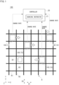
- FIG. 1 is a diagram for describing a processing example of a transport vehicle system according to the embodiment.
- a transport vehicle system 100 is a system to transport articles 1 (see Fig. 3 and so forth) such as FOUPs (Front-Opening Unified Pods) containing semiconductor wafers and reticle pods containing reticles in a clean room of a semiconductor manufacturing factory, for example.
- FOUPs Front-Opening Unified Pods
- a transport vehicle 10 that travels on a grid-patterned track R suspended from the ceiling will be described as an example.
- the transport vehicle 10 may be a track-guided transport vehicle or a trackless transport vehicle that travels on the ground.
- the transport vehicle system 100 includes a plurality of transport vehicles 10 that transport articles 1, a controller 20 that assigns a transport instruction to one of the plurality of transport vehicles 10, and a charger 30 that is located on a route (for example, the grid-patterned track R) along which the plurality of transport vehicles 10 can move and that supplies electric power to the transport vehicles 10.
- a route for example, the grid-patterned track R
- Each transport vehicle 10 can move in a first direction D1 and a second direction D2 along the grid-patterned track R that extends in the first direction D1 and the second direction D2 intersecting the first direction D1.
- the grid-patterned track R is a type of track and is installed near the ceiling of a clean room.
- the charger 30 is provided so as to correspond to one of grid cells of the grid-patterned track R.
- the charger 30 supplies electric power to a battery 116 of the transport vehicle 10 (see Fig. 4 ).
- the grid-patterned track R has first tracks R1 provided along the X direction (for example, the first direction D1), second tracks R2 provided along the Y direction (for example, the second direction D2), and partial tracks R3 provided at intersections of the first tracks R1 and the second tracks R2.
- the four transport vehicles 10 are presented as transport vehicle 10A, transport vehicle 10B, transport vehicle 10C, and transport vehicle 10D, respectively. When not specifically distinguishing between the transport vehicle 10A, the transport vehicle 10B, the transport vehicle 10C, and the transport vehicle 10D, they will be simply referred to as "transport vehicle 10".
- the number of transport vehicles 10 is not limited to four.
- Each transport vehicle 10 transmits its own state information to the controller 20 in response to a request (periodic request) from the controller 20.
- the controller 20 acquires state information of the multiple transport vehicles 10 through periodic communication with the multiple transport vehicles 10, and assigns a transport instruction to one of the transport vehicle 10 on the basis of the acquired state information.
- the state information includes, for example, identification information for identifying the transport vehicle 10, along with information related to the current location, destination, traveling state (for example, on standby, charging, traveling for pickup, traveling for unloading), and charge rate (remaining battery level).
- the transport vehicle 10 travels on the grid-patterned track R upon receiving a transport instruction from the controller 20.
- the transport instruction includes information on the transport route along which the transport vehicle 10 transporting an article 1 is scheduled to travel.
- the information on the transport route is information that designates at least a part of the traveling route from an origin to a destination of the transport vehicle 10.
- the controller 20 includes a charging instructor 21 that instructs to start charging each transport vehicle 10.
- the charging instructor 21 performs a first determination process to determine whether the charge rate of the entire multiple transport vehicles 10 is below a first threshold value, and instructs to start charging at least any one of the transport vehicles 10 if the charge rate of the entire multiple transport vehicles 10 is determined as being below the first threshold value.
- the charging instructor 21 calculates the charge rate for all of the multiple transport vehicles 10 present on the grid-patterned track R, on the basis of the information related to the charge rate (remaining battery level) contained in the state information received from each transport vehicle 10. Then, the charging instructor 21 performs the first determination process to determine whether the calculated charge rate of the entire multiple transport vehicles 10 are below the first threshold value.
- the charging instructor 21 instructs to start charging at least any one of the transport vehicles 10 if the charge rate of the entire multiple transport vehicles 10 is determined as being below the first threshold value in the first determination process.
- the number of transport vehicles 10 to which the charging start instruction is to be given may be set in advance, on the basis of the scale of the transport vehicle system 100, the number of transport vehicles 10 to be introduced, and so forth.
- the charging instructor 21 may identify the transport vehicle 10 whose charge rate is below the first threshold value on the basis of the information on the charge rate (remaining battery level) contained in the state information of each transport vehicle 10, and instruct to start charging the identified transport vehicles 10. At this time, the charging instructor 21 may instruct to start charging at least any one of the transport vehicles 10 whose charge rate is below the first threshold value.
- the charging instructor 21 performs a second determination process to determine whether the charge rate of each transport vehicle 10 is below a second threshold value that is lower than the first threshold value, and instructs to start charging each transport vehicle 10 if the charge rate of the transport vehicle 10 is determined as being below the second threshold value. Specifically, the charging instructor 21 performs the second determination point process to determine whether the charge rate of each transport vehicle 10 is below the second threshold value that is lower than the first threshold value, on the basis of information related to the charge rate (remaining battery level) contained in the state information received from each transport vehicle 10. At this time, the charging instructor 21 identifies the transport vehicle 10 whose charge rate is below the second threshold value through the second determination process, and instructs to start charging the identified transport vehicle 10.
- the second threshold value is, for example, a level requiring charging relative to the charge rate of the battery 116. That is to say, the controller 20 charges at least any one of the transport vehicles 10 when the overall charge rate of the system falls below a certain level, using the first threshold value, which is a level requiring charging and higher than the second threshold value, as the threshold value for the charge rate of the entire multiple transport vehicles 10. Thus, it is possible to shift the timing of instructing to start charging, and suppress a decrease in the transport efficiency of the entire transport vehicle system 100. In other words, the controller 20 determines which transport vehicle 10 should start charging by comparing the charge rate of the entire system with the threshold value, and directs the transport vehicle 10 that would not normally require charging yet to the charger 30.
- the controller 20 preemptively instructs to charge the transport vehicle 10 with a low charge rate from the perspective of the entire system, even if the transport vehicle 10 would not normally require charging yet.
- the controller 20 preemptively instructs to charge the transport vehicle 10 with a low charge rate from the perspective of the entire system, even if the transport vehicle 10 would not normally require charging yet.
- it is possible to suppress a decrease in the transport efficiency of the entire transport vehicle system 100 without transport vehicles 10 that require charging (at the level requiring charging) occurring in a short period of time.
- the charging instructor 21 may check the system margin rate, which indicates a degree of margin in the entire multiple transport vehicles 10, at predetermined timings against the processing of transport instructions, and instruct to start charging any one of the transport vehicles 10 if the degree of margin indicated by the system margin rate is higher than or equal to a predetermined degree and also the charge rate of the entire multiple transport vehicles 10 is determined as being below the first threshold value.
- the charging instructor 21 may instruct to start charging a transport vehicle 10 (a transport vehicle 10 with a charge rate below the second threshold value) if the degree of margin indicated by the system margin rate is higher than or equal to the predetermined degree and also the charge rate of the transport vehicle 10 is determined as being below the second threshold value.
- the charging instructor 21 checks whether or not at least one of following conditions is satisfied: the effective transport vehicle ratio, which serves as the system margin rate to represent the proportion of transport vehicles 10 that are on standby relative to the entire multiple transport vehicles 10, is higher than or equal to a predetermined ratio; the transport volume of the entire multiple transport vehicles 10 is below a predetermined transport volume; and the utilization rate of the entire multiple transport vehicles 10 is below a predetermined utilization rate. If at least one of these conditions is satisfied, it is determined that there is a sufficient system margin.
- the effective transport vehicle ratio corresponds to the ratio of transport vehicles 10 that can execute transport instructions (that are available for executing transport instructions), and can be found, for example, by calculating the ratio of transport vehicles 10 on standby to the total number of transport vehicles 10, on the basis of the traveling state contained in state information.
- the transport volume corresponds to the number of transport instructions per unit time, or the weighted value for transport instructions with longer transport distances added to the number of transport instructions per unit time.
- the utilization rate corresponds to the ratio of transport vehicles 10 that are operating throughout the entire transport vehicle system 100, and can be found, for example, by calculating the ratio of transport vehicles 10 that are currently traveling for pickup or traveling for unloading, on the basis of the traveling state contained in state information.
- the threshold value for each item of the system margin rate can be set as appropriate, depending on the layout, transport pattern, and so forth of the transport vehicle system 100.
- the predetermined transport distance may be set smaller than the limit value of the transport distance at which the transport instructions can be processed by the entire multiple transport vehicles 10, thereby allowing a margin in the execution of transport.
- the predetermined utilization rate may be set lower than the limit value of the utilization rate of the entire multiple transport vehicles 10, thereby allowing a margin in the number of operational transport vehicles 10.
- the charging instructor 21 checks the system margin rate periodically at predetermined timings. For example, the cycle for checking the system margin rate is longer than the cycle for sending state information from each transport vehicle 10.
- the cycle for checking the system margin rate is approximately once per minute, whereas the cycle for transmitting state information is once every few seconds.
- the charging instructor 21 executes the first determination process and the second determination process.
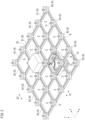
- Fig. 2 is a perspective view showing an example of the transport vehicle system according to the embodiment.
- the transport vehicle system 100 is a system to transport articles 1 such as FOUPs containing semiconductor wafers and reticle pods containing reticles in a clean room of a semiconductor manufacturing factory, for example.
- the transport vehicles 10 and the charger 30 are arranged on the grid-patterned track R.
- the grid-patterned track R is provided in a state of being suspended from the ceiling via suspenders H.
- Multiple first tracks R1 are provided along the X direction (for example, the first direction D1).
- Multiple second tracks R2 are provided along the Y direction (for example, the second direction D2).
- the partial track R3 is arranged at each portion where the first track R1 and the second track R2 intersect with each other. Between the first track R1 and the partial track R3 and between the second track R2 and the partial track R3, there is provided a gap D.
- the gap D is a portion through which a coupler 130 (see Fig. 3 ) serving as a part of the transport vehicle 10 passes when the transport vehicle 10 having traveled on the first track R1 crosses the second track R2 or when the transport vehicle 10 having traveled on the second track R2 crosses the first track R1.
- the gap D is provided with a width that allows the coupler 130 to pass therethrough.
- the first tracks R1, the second tracks R2, and the partial tracks R3 are provided along the same or substantially the same horizontal plane.
- the first tracks R1 and the second tracks R2 orthogonally intersect with each other, thereby establishing a state where a plurality of cells C are adjacent to each other as viewed in a plan view.
- a single cell C is a region or a space surrounded by two first tracks R1 adjacent to each other in the Y direction and two second tracks R2 adjacent to each other in the X direction.
- Fig. 3 is a perspective view showing an example of the transport vehicle according to the embodiment.
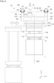
- Fig. 4 is a front elevation view showing an example of the transport vehicle according to an embodiment.
- the transport vehicle 10 has a main body 110, travelers 120, couplers 130, and a controller 140.
- the transport vehicle 10 moves along the grid-patterned track R and transports articles 1 such as FOUPs and reticle pods.
- Multiple transport vehicles 10 may be arranged in the grid-patterned track R.
- the main body 110 is arranged below the grid-patterned track R (on the -Z side).
- the main body 110 is formed, for example, in a rectangular shape as seen in a plan view. Therefore, an upper face 110a of the main body 110 has a rectangular shape and has four corners.
- the main body 110 is formed in a size that fits in a single cell C within the grid-patterned track R as viewed in a plan view. Therefore, in the grid-patterned track R, there is no interference between the transport vehicles 10 traveling adjacent to each other.
- the main body 110 has an article holder 113 to hold an article 1, a lift driver 114 to raise or lower the article holder 113 in the vertical direction, and a lateral extender 111 to move the lift driver 114.
- the article holder 113 suspends and holds an article 1 by grasping a flange 1a provided on the upper part of the article 1.
- the article holder 113 is, for example, a chuck having claws 113a movable in the horizontal direction, and inserts the claws 113a under the flange 1a of the article 1 and lifts the article holder 113, to thereby suspend and hold the article 1.
- the article holder 113 is connected to the lower end of suspenders 113b such as wires and belts.
- the lift driver 114 is, for example, a hoist, and lowers the article holder 113 by feeding out the suspenders 113b and lifts the article holder 113 by taking up the suspenders 113b.
- the lift driver 114 is controlled by the controller 140 to raise or lower the article holder 113 at a predetermined speed. Also, the lift driver 114 is controlled by the controller 140 to maintain the article holder 113 at a target height.
- the lateral extender 111 has a plurality of movable plates arranged stacked, for example, in the Z direction. The movable plates can move in the Y direction.
- the lift driver 114 is mounted on the lowermost movable plate.
- the lateral extender 111 can, by moving the movable plates by means of a driver not shown in the drawings, extend laterally with respect to the traveling direction the lift driver 114 attached to the lowermost movable plate and the article holder 113.
- the rotator 112 has a rotation member 112a and a rotation driver 112b.
- the rotation member 112a is provided so as to be rotatable in an axial direction about the Z axis.
- the rotation member 112a supports the lateral extender 111.
- An electric motor or the like is used for the rotation driver 112b and causes the rotation member 112a to rotate in the axial direction about the Z direction axis.
- the rotator 112 can, by rotating the rotation member 112a by means of the driving force from the rotation driver 112b, rotate the lateral extender 111 (the lift driver 114 and the article holder 113) in the axial direction about the Z direction axis.
- a rotator to control the attitude of the lift driver 114 and the article holder 113 within the horizontal plane may be further provided between the lateral extender 111 and the lift driver 114.
- the main body 110 includes a battery 116 and charging electrodes 117.
- the battery 116 is arranged inside the main body 110.
- the battery 116 stores electric power to be supplied to the travelers 120, the rotation driver 112b, the lift driver 114, and so forth of the transport vehicle 10.
- a secondary battery such as a lithium ion battery is used for the battery 116.
- the capacity of the battery 116 is determined on the basis of electric power used in the transport vehicle 10, operating time thereof, and so forth.
- the charging electrodes 117 are held by a holder 118 and are arranged on the upper face 110a of the main body 110.
- the charging electrodes 117 are provided side by side at two locations on the upper face side of the holder 118.
- One of the two charging electrodes 117 is electrically connected to the + side terminal of the battery 116.
- the other charging electrode 117 is electrically connected to the - side terminal of the battery 116. Electric power is supplied to the battery 116 from the charger 30 (a terminal 31 of the charger 30) via the charging electrodes 117.
- Each traveler 120 has a traveling wheel 121 and auxiliary wheels 122.
- the traveling wheel 121 is arranged in each of the four corners on the upper face 110a of the main body 110.
- Each traveling wheel 121 is rotatably supported on the coupler 130 by a rotation shaft not shown in the drawings. This rotation shaft is provided in parallel or substantially parallel along the XY plane (horizontal plane). Therefore, the traveling wheel 121 can rotate about the axis line of the rotation shaft along the horizontal direction.
- Each traveling wheel 121 is driven to rotate by the driving force of a traveling driver 133.
- Each traveling wheel 121 rolls on the traveling surfaces of the first track R1, the second track R2, and the partial track R3 of the grid-patterned track R, causing the transport vehicle 10 to travel.
- Each traveling wheel 121 is provided so as to be able to pivot in the ⁇ Z direction about the pivot axis AX1 along the Z direction.
- the traveling wheel 121 can, by pivoting in the ⁇ Z direction, change the traveling direction thereof from the first direction D1 to the second direction D2 or from the second direction D2 to the first direction D1.
- the configuration is not limited to driving all of the four traveling wheels 121 to rotate by the drive force of the traveling driver 133, and some of the four traveling wheels 121 may be driven to rotate.
- the auxiliary wheels 122 are each arranged in front and rear of the traveling wheel 121 in the traveling direction. As with the traveling wheel 121, each auxiliary wheel 122 can rotate about the axis line of the rotation axis thereof parallel or substantially parallel along the XY plane. The lower end of the auxiliary wheel 122 is arranged higher than the lower end of the traveling wheel 121. Therefore, when the traveling wheel 121 is traveling on the traveling surfaces, the auxiliary wheels 122 do not come into contact with the traveling surfaces. When the traveling wheel 121 passes through the gap, the auxiliary wheels 122 come into contact with the traveling surfaces, preventing the traveling wheel 121 from falling.
- the configuration is not limited to providing two auxiliary wheels 122 for a single traveling wheel 121, and for example, a single auxiliary wheel 122 may be provided for a single traveling wheel 121, or no auxiliary wheel 122 may be provided.
- the coupler 130 connects the main body 110 and the traveler 120.
- the coupler 130 is provided at each of the four corners on the upper face 110a of the main body 110.
- the main body 110 is suspended by the coupler 130 and is arranged below the grid-patterned track R.
- the coupler 130 has a support member 131 and a connection member 132.
- the support member 131 rotatably supports the rotation axle of the traveling wheel 121 and the rotation axles of the auxiliary wheels 122. The relative positions between the traveling wheel 121 and the auxiliary wheel 122 are maintained by the support member 131.
- connection member 132 extends downward from the support member 131 and is coupled to the upper face 110a of the main body 110 to hold the main body 110.
- the connection member 132 therein includes a transmission for transmitting the driving force of the traveling driver 133 to the traveling wheel 121.
- This transmission may be of a configuration in which a chain or a belt is used, or a configuration in which a gear train is used.
- the connection member 132 is provided so as to be able to pivot in the ⁇ Z direction about the pivot axis AX1. The rotation of the connection member 132 about the pivot axis AX1 can cause the traveling wheel 121 to pivot in the ⁇ Z direction.
- the traveling driver 133 and the steerer 134 are provided in the coupler 130.
- the traveling driver 133 is attached to the connection member 132.
- the traveling driver 133 is a drive source for driving the traveling wheel 121, and for example, an electric motor or the like is used therefor.
- Each of the four traveling wheels 121 is driven by the traveling driver 133 to serve as a driving wheel.
- the four traveling wheels 121 are controlled by the controller 140 so as to rotate at the same or substantially the same rotation speed.
- the steerer 134 causes the connection member 132 of the coupler 130 to rotate about the pivot axis AX1 to thereby cause the traveling wheel 121 to pivot in the ⁇ Z direction.
- the traveling direction of the transport vehicle 10 can be changed from the first direction D1 to the second direction D2 or from the second direction D2 to the first direction D1, by causing the traveling wheel 121 to pivot in the ⁇ Z direction.
- the steerer 134 has a drive source 135, and a pinion gear and a rack 137, which are not shown in the drawings.
- the drive source 135 is mounted on a side face of the traveling driver 133 away from the pivot axis AX1.
- the pinion gear is mounted on the lower face side of the drive source 135, and is driven to rotate in the ⁇ Z direction by the driving force generated by the drive source 135.
- the pinion gear is of a circular shape as seen in a plan view and has a plurality of teeth on the outer circumference thereof along the circumferential direction.
- the rack 137 is fixed to the upper face 110a of the main body 110.
- the rack 137 is provided at each of the four corners on the upper face 110a of the main body 110, and is provided having an arc shape centered on the pivot axis AX1 of the traveling wheel 121.
- the rack 137 has multiple teeth which mesh with the teeth of the pinion gear, on the outer circumference thereof along the circumferential direction.
- the pinion gear and the rack 137 are each arranged in the state where the teeth of the pinion gear and the teeth of the rack 37 are in mesh with each other.
- the pinion gear rotates in the ⁇ Z direction, the pinion gear moves in the circumferential direction about the pivot axis AX1 along the outer circumference of the rack 137.
- This movement of the pinion gear causes the traveling driver 133 and the steerer 134 to pivot together with the pinion gear in the circumferential direction about the pivot axis AX1.
- Fig. 5 is a diagram showing an example of transmitting and receiving state information according to the embodiment.
- the controller 20 transmits a state information request to each of the transport vehicles 10 (for example, transport vehicles 10A, 10B, 10C, and 10D) through periodic communication.
- each transport vehicle 10 transmits its state information to the controller 20.
- the transport vehicle 10A transmits its own state information S1 (state information S1A) to the controller 20.
- the transport vehicle 10B similarly transmits its own state information S2 (state information S2A) to the controller 20.
- the transport vehicle 10C similarly transmits its own state information S3 (state information S3A) to the controller 20.
- the transport vehicle 10D similarly transmits its own state information S4 (state information S4A) to the controller 20.
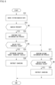
- Fig. 6 is a flowchart showing an example of the flow of processing performed by a controller according to the embodiment.
- Fig. 6 shows an example in which the system margin rate is checked prior to the execution of the first determination process and the second determination process.
- the charging instructor 21 checks the system margin rate (Step S01). Specifically, the charging instructor 21 checks whether at least one of the following is satisfied: the effective transport vehicle ratio is higher than or equal to a predetermined ratio; the transport volume is lower than a predetermined transport volume; and the utilization rate is lower than a predetermined utilization rate. Then, if there is a margin in the system margin rate (Step S02: YES), the charging instructor 21 executes the first determination process (Step S03).
- the charging instructor 21 upon determining that there is a margin by checking the system margin rate, calculates the charge rate for all of the multiple transport vehicles 10 present on the grid-patterned track R, on the basis of the information related to the charge rate contained in the state information received from each transport vehicle 10.
- Step S04 determines the charging target transport vehicle 10 to be charged (Step S05) and instructs to charge the determined charging target transport vehicle 10 (Step S06). Specifically, if the calculated charge rate for the entire multiple transport vehicles 10 is determined as being below the first threshold value, the charging instructor 21 determines at least one of the transport vehicles 10 as a charging target and instructs to start charging the transport vehicle 10 determined as the charging target. That is to say, when the system margin rate has a margin and the charge rate of the entire system is below the first threshold value, the controller 20 prompts at least one of the transport vehicles 10 to charge early.
- Step S07 the charging instructor 21 executes the second determination process (Step S07). Specifically, the charging instructor 21, upon determining that there is no margin by checking the system margin rate, determines whether the charge rate of each transport vehicle 10 is below the second threshold value that is lower than the first threshold value, on the basis of the information related to the charge rate contained in the state information received from each transport vehicle 10. Then, if the charge rate is below the second threshold value on the basis of the second determination process (Step S08: YES), the charging instructor 21 instructs to charge the transport vehicle 10 (Step S09).
- the charging instructor 21 instructs to charge the transport vehicle 10.
- the charging instructor 21 ends the processing. Specifically, if there is no transport vehicle 10 whose charge rate is below the second threshold value as a result of the second determination process, the charging instructor 21 ends the processing because there is no transport vehicle 10 that currently requires charging. In other words, if there is no margin in the system margin rate, the controller 20 prompts to charge the transport vehicle 10 that requires charging, without prompting to charge at a timing that is different from the usual timing.
- the charging instructor 21 executes the second determination process. Specifically, the charging instructor 21, upon determining that the calculated charge rate of the entire multiple transport vehicles 10 is not below the first threshold value, determines whether the charge rate of each transport vehicle 10 is below the second threshold value that is lower than the first threshold value, on the basis of the information related to the charge rate contained in the state information received from each transport vehicle 10. That is to say, when the system margin rate has a margin and the charge rate of the entire system is not below the first threshold value, the controller 20 checks whether or not there is any transport vehicle 10 that requires charging. In other words, when the charge rate of the entire system is relatively high but there is a transport vehicle 10 that requires charging, the controller 20 prompts to charge the transport vehicle 10.
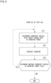
- Fig. 7 is a diagram for describing another processing example of the charging instructor according to the embodiment.
- the charging instructor 21 may instruct to start charging two or more transport vehicles at different timings. Specifically, when instructing to start charging two or more transport vehicles, the charging instructor 21 may instruct to start charging the transport vehicles 10 in order from the transport vehicle 10 closest to the charger 30.
- the charging instructor 21 determines the transport vehicle 10 closest to the charger 30 as a charging target (Step S21) and instructs to charge the transport vehicle 10 determined as the charging target (Step S22). Specifically, the charging instructor 21, upon determining that the calculated charge rate of the entire multiple transport vehicles 10 is below the first threshold value, determines the transport vehicle 10 that is closest to the charger 30 as a charging target on the basis of information related to the current location contained in the state information of each transport vehicle 10. Thereafter, the charging instructor 21 instructs to charge the transport vehicle 10 determined as the charging target.
- Step S23 YES
- the charging instructor 21 executes the process of Step S21 again.
- Step S23: NO the charging instructor 21 ends the processing. Specifically, after having instructed to charge a transport vehicle 10 determined as a charging target, if another transport vehicle 10 is also determined as a charging target, the charging instructor 21 determines the transport vehicle 10 closest to the charger 30 as being a charging target and instructs to charge the transport vehicle 10 that is determined as the charging target. After having instructed to charge the transport vehicle 10 determined as being a charging target, if another transport vehicle 10 is not determined as the charging target, the charging instructor 21 ends the processing.
- the controller 20 may execute the instructions at certain intervals. In other words, the controller 20 instructs to charge the transport vehicles 10 closest to the charger 30 (in order from the transport vehicle 10 closest to the charger 30) at certain intervals between the instruction, because it is undesirable for the transport efficiency to decrease due to a charging wait that arises when multiple transport vehicles 10 are sent for charging at the same time. Also, in the case where a transport vehicle 10 with a charging rate below the first threshold value is determined as a charging target, if multiple transport vehicles 10 are charging targets, the charging instructor 21 may instruct to charge the charging target transport vehicles 10 in order from the transport vehicle 10 closest to the charger 30, at certain intervals.
- Fig. 8 is a diagram for describing another processing example of the charging instructor according to the embodiment.
- the charging instructor 21 may instruct to start charging two or more transport vehicles at different timings. Specifically, when instructing to start charging two or more transport vehicles, the charging instructor 21 may instruct to start charging the transport vehicles 10 in order from the transport vehicle 10 with the lowest charge rate.
- the charging instructor 21 determines the transport vehicle 10 with the lowest charge rate as a charging target (Step S31) and instructs to charge the transport vehicle 10 determined as the charging target (Step S32). Specifically, the charging instructor 21, upon determining that the calculated charge rate of the entire multiple transport vehicles 10 is below the first threshold value, determines the transport vehicle 10 with the lowest charge rate as a charging target, on the basis of information related to the charge rate contained in the state information of each transport vehicle 10. Then, the charging instructor 21 instructs to charge the transport vehicle 10 determined as the charging target.
- Step S33: YES If another transport vehicle 10 is also determined as being a charging target (Step S33: YES), the charging instructor 21 executes the process of Step S31 again. On the other hand, if another transport vehicles 10 is not determined as being a charging target (Step S33: NO), the charging instructor 21 ends the processing. Specifically, after having instructed to charge a transport vehicle 10 determined as a charging target, if another transport vehicle 10 is also determined as a charging target, the charging instructor 21 determines the transport vehicle 10 with the lowest charge rate as being a charging target and instructs to charge the transport vehicle 10 that is determined as the charging target. After having instructed to charge the transport vehicle 10 determined as being a charging target, if another transport vehicle 10 is not determined as the charging target, the charging instructor 21 ends the processing.
- the controller 20 may execute the instructions at certain intervals. In other words, the controller 20 instructs to charge the transport vehicles 10 with the lowest charge rate (in order from the transport vehicle 10 with the lowest charge rate) at certain intervals between the instruction, because it is undesirable for the transport efficiency to decrease due to a charging wait that arises when multiple transport vehicles 10 are sent for charging at the same time. Also, in the case where a transport vehicle 10 with a charging rate below the first threshold value is determined as a charging target, if multiple transport vehicles 10 are charging targets, the charging instructor 21 may instruct to charge the charging target transport vehicles 10 in order from the transport vehicle 10 with the lowest charge rate, at certain intervals.
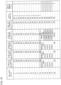
- Fig. 9 is a diagram showing an example of a charging instruction processing image according to the embodiment.
- description is premised on that three chargers 30 are arranged, the battery 116 decreases by 1 percent per minute, the travel time for charging is 1 minute, and the charging time is 4 minutes.
- the first threshold value (corresponding to the charging rate of the entire system) is "30" percent
- the second threshold value (corresponding to the charging rate of each individual transport vehicle 10) is "20" percent.
- the effective transport vehicle ratio is taken as an example of the system margin rate where the threshold value thereof is set to "60" percent.
- the controller 20 calculates the charge rate of the entire multiple transport vehicles 10 every minute, and recognizes it falling below the first threshold value of "30" percent as the overall charge rate becomes “29.2" percent when "4" minutes have elapsed.
- the controller 20 treats transport vehicles V1, V2, V3, and V4 as charging targets. Then, the controller 20 instructs to charge any one of the transport vehicles 10, the transport vehicle 10 that is closest to the charger 30, or the transport vehicle 10 with the lowest charge rate among the transport vehicles V1, V2, V3, and V4.
- the controller 20 instructs to charge any one of the transport vehicles 10, the transport vehicle 10 that is closest to the charger 30, or the transport vehicle 10 with the lowest charge rate among the transport vehicles V1, V2, V3, and V4.
- the controller 20 may instruct to charge any transport vehicle 10, or the transport vehicle 10 closest to the charger 30, and it instructs to charge the transport vehicle V1, for example. Since there is an available charger 30 and there is a margin in the system margin rate (here, the effective transport vehicle ratio), the controller 20 instructs to charge the transport vehicle V2. Although the charging instructions to the transport vehicles V1, V2 are executed at different timings, they may be executed at the same timing. At this time, if the controller 20 instructs to charge either the transport vehicle V3 or V4, the system margin rate (here, the effective transport vehicle ratio) will fall below the threshold value of "60" percent, and therefore, the controller 20 does not instruct to charge the transport vehicles V3, V4.
- the system margin rate here, the effective transport vehicle ratio
- the controller 20 recognizes the completion of charging the transport vehicles V1, V2. At this time, the controller 20 does not instruct to charge the transport vehicles V3, V4 because there is a margin in the system margin rate (here, the effective transport vehicle ratio), the charge rate of the entire system is not below the first threshold value of "30" percent and the individual charge rates are not below the second threshold value of "20" percent.
- the controller 20 recognizes the individual charge rates of the transport vehicles V1, V2 falling below the second threshold value of "20” percent. The controller 20 then instructs to charge the transport vehicles V3, V4. Then, when "18" minutes have elapsed, the controller 20 recognizes the completion of charging the transport vehicles V3, V4.
- Fig. 10 is a diagram showing an example of a charging instruction processing image according to the conventional technique.
- the conventional technique when "12" minutes have elapsed, the individual charge rates of the transport vehicles V1, V2, V3, and V4 fall below the threshold value (the second threshold value in the present embodiment), and charging becomes necessary.
- the transport vehicles V1, V2, and V3 are directed to the chargers, and the transport vehicle V4 is placed on standby for charging. At this time, the number of transport vehicles that are able to operate in the entire system will be "1" (transport vehicle V5), and this reduces the transport efficiency.
- any one of the transport vehicles 10 is instructed to start charging if the charge rate of the entire plurality of transport vehicles 10 is below the first threshold value, and each transport vehicle 10 the charge rate of which is below the second threshold value that is lower than the first threshold value is instructed to start charging.
- charging instructions for the transport vehicles are given taking the system margin rate into account.
- the system margin rate is periodically checked while giving charging instructions to the transport vehicles 10.
- the system margin rate is found using various information related to the transport efficiency.
- multiple transport vehicles 10 are not sent to charge at the same time.
- the transport vehicles 10 are instructed to start charging in order from the transport vehicle 10 closest to the charger 30.
- the transport vehicles 10 are instructed to start charging in order from the transport vehicle 10 with the lowest charge rate. Thus, it is possible to prevent the increase in the number of transport vehicles 10 being unable to execute transport instructions due to a reduced charge rate.
- state information is acquired through periodic communication between the multiple transport vehicles 10 and the controller 20. Thus, it is possible to identify transport vehicles 10 that are suitable for instructing charging.
- the multiple transport vehicles 10 can move in the first direction D1 or the second direction D2 along the grid-patterned track R, and the charger 30 is provided so as to correspond to one of the grid cells of the grid-patterned track R. Thus, it is possible to apply the present invention to a transport vehicle system 100 arranged on a grid-patterned track R.
Landscapes
- Engineering & Computer Science (AREA)
- Power Engineering (AREA)
- Mechanical Engineering (AREA)
- Transportation (AREA)
- Sustainable Energy (AREA)
- Life Sciences & Earth Sciences (AREA)
- Sustainable Development (AREA)
- Automation & Control Theory (AREA)
- Aviation & Aerospace Engineering (AREA)
- Radar, Positioning & Navigation (AREA)
- Remote Sensing (AREA)
- Physics & Mathematics (AREA)
- General Physics & Mathematics (AREA)
- Control Of Position, Course, Altitude, Or Attitude Of Moving Bodies (AREA)
- Electric Propulsion And Braking For Vehicles (AREA)
- Management, Administration, Business Operations System, And Electronic Commerce (AREA)
Abstract
Description
- The present invention relates to a transport vehicle system and a method of controlling transport vehicles.
- Conventionally, transport vehicle systems that transport articles in factories and the like on the basis of transport instructions are known. In these transport vehicle systems, transport vehicles, which transport articles on the basis of transport instructions, are equipped with driving batteries, and charging facilities are provided to charge the batteries while the vehicles are stationary.
Patent Literature 1 discloses a technique in which, when causing a transport vehicle with a battery voltage that has dropped to a level requiring charging to travel to the charging facility for charging, the transport vehicle that has been charging at each charging facility and has had the longest charging time is dispatched, ensuring a certain number of transport vehicles remain available on the main route. - [Patent Literature 1]
Japanese Patent No. 4539887 - In the conventional technique, the battery voltage of each transport vehicle is checked individually, and any transport vehicle that has dropped to a level requiring charging is sent to be charged at a charging facility, and one of the transport vehicles that is already charging at the charging facility is returned to the main route while charging is still in progress. In other words, in the conventional technique, when multiple transport vehicles drop to a level requiring charging at the same time, multiple transport vehicles that are already charging at the charging facility are caused to return to the main route at the same time. As a result, in conventional technique, the presence of multiple transport vehicles within the system that are not fully charged means that transport vehicles in the system as a whole will need to be charged in a short period of time, resulting in a reduction in the transport efficiency of the entire system.
- Thus, the present invention provides a transport vehicle system and a method of controlling transport vehicles capable of suppressing a decrease in the transport efficiency of the entire system.
- A transport vehicle system according to an aspect of the present invention is a transport vehicle system comprising: a plurality of transport vehicles that transport articles; a controller that assigns a transport instruction to any one of the plurality of transport vehicles; and a charger that is located on a route along which the plurality of transport vehicles can travel and supplies electric power to the transport vehicles, wherein the controller includes a charging instructor that instructs to start charging each transport vehicle, wherein the charging instructor performs a first determination process to determine whether a charge rate of an entirety of the plurality of transport vehicles is below a first threshold value, and instructs to start charging at least any one of the transport vehicles if the charge rate of the entirety of the plurality of transport vehicles is determined as being below the first threshold value, and wherein the charging instructor performs a second determination process to determine whether the charge rate of each transport vehicle is below a second threshold value that is lower than the first threshold value, and instructs to start charging each transport vehicle if the charge rate of the transport vehicle is determined as being below the
- A method of controlling transport vehicles according to an aspect of the present invention is a method of controlling transport vehicles in a transport vehicle system comprising a plurality of transport vehicles that transport articles, a controller that assigns a transport instruction to any one of the plurality of transport vehicles, and a charger that is located on a route along which the plurality of transport vehicles can travel and supplies electric power to the transport vehicles, the method comprising steps, implemented by the controller, of: performing a first determination process to determine whether a charge rate of an entirety of the plurality of transport vehicles is below a first threshold value, and instructing to start charging at least any one of the transport vehicles if the charge rate of the entirety of the plurality of transport vehicles is determined as being below the first threshold value; and performing a second determination process to determine whether the charge rate of each transport vehicle is below a second threshold value that is lower than the first threshold value, and instructing to start charging each transport vehicle if the charge rate of the transport vehicle is determined as being below the second threshold value.
- According to the transport vehicle system and the method of controlling transport vehicles according to an aspect of the present invention, any one of the transport vehicles is instructed to start charging if the charge rate of the entire plurality of transport vehicles is below the first threshold value, and each transport vehicle the charge rate of which is below the second threshold value that is lower than the first threshold value is instructed to start charging. Thus, compared to the conventional technique, which instructs to start charging using only the individual charge rates of transport vehicles, it is possible to suppress multiple transport vehicles from being instructed to start charging at the same timing, thereby suppressing a decrease in the transport efficiency of the entire system.
- In the transport vehicle system of the above aspect, the charging instructor may check a system margin rate, which indicates a degree of margin in the entirety of the plurality of transport vehicles, at predetermined timings against processing of the transport instruction, instruct to start charging any one of the transport vehicles if the degree of margin indicated by the system margin rate is higher than or equal to a predetermined degree and also the charge rate of the entirety of the plurality of transport vehicles is determined as being below the first threshold value, and instruct to start charging a transport vehicle if the degree of margin indicated by the system margin rate is higher than or equal to the predetermined degree and also the charge rate of the transport vehicle is determined as being below the second threshold value. According to such an aspect, charging instructions for the transport vehicles are given taking the system margin rate into account. Thus, it is possible to prevent situations where there is no transport vehicle to which a transport instruction can be assigned. In the transport vehicle system of the above aspect, the charging instructor may check the system margin rate periodically at the predetermined timings. According to such an aspect, the system margin rate is periodically checked while giving charging instructions to the transport vehicles. Thus, it is possible to prevent situations transport vehicles become unable to execute transport instructions due to a reduced charge rate. In the transport vehicle system of the above aspect, the charging instructor may check whether or not at least one of following is satisfied: an effective transport vehicle ratio, which serves as the system margin rate to represent a proportion of transport vehicles that are on standby relative to the entirety of the plurality of transport vehicles, is higher than or equal to a predetermined ratio; a transport volume of the entirety of the plurality of transport vehicles is below a predetermined transport volume; and a utilization rate of the entirety of the plurality of transport vehicles is below a predetermined utilization rate. According to such an aspect, in the transport vehicle system, the system margin rate is found using various information related to the transport efficiency. Thus, it is possible to suitably suppress a decrease in the transport efficiency of the entire system. In the transport vehicle system of the above aspect, if there are multiple vehicles having a charge rate below the first threshold value, the charging instructor may instruct to start charging two or more of the transport vehicles at different timings. According to such an aspect, multiple transport vehicles are not sent to charge at the same time. Thus, it is possible to suppress a decrease in the transport efficiency of the entire system. In the transport vehicle system of the above aspect, the charging instructor may instruct to start charging the transport vehicles in order from the transport vehicle closest to the charger. According to such an aspect, when multiple transport vehicles require charging, it is possible to improve charging efficiency. In the transport vehicle system of the above aspect, the charging instructor may instruct to start charging the transport vehicles in order from the transport vehicle with the lowest charge rate. According to such an aspect, it is possible to prevent an increase in the number of transport vehicles being unable to execute transport instructions due to a reduced charge rate. In the transport vehicle system of the above aspect, the controller may acquire state information of the plurality of transport vehicles through periodic communication with the plurality of transport vehicles. According to such an aspect, it is possible to identify the transport vehicles that are suitable for instructing charging. In the transport vehicle system of the above aspect, the plurality of transport vehicles may be able to move in a first direction and a second direction along a grid-patterned track that extends in a first direction and a second direction intersecting the first direction, and the charger may be provided so as to correspond to one of grid cells of the grid-patterned track. According to such an aspect, the present invention can be applied to a transport vehicle system arranged on a grid-patterned track.
-
-
Fig. 1 is a diagram for describing a processing example of a transport vehicle system according to an embodiment. -
Fig. 2 is a perspective view showing an example of the transport vehicle system according to the embodiment. -
Fig. 3 is a perspective view showing an example of a transport vehicle according to the embodiment. -
Fig. 4 is a front elevation view showing an example of the transport vehicle according to an embodiment. -
Fig. 5 is a diagram showing an example of transmitting and receiving state information according to the embodiment. -
Fig. 6 is a flowchart showing an example of the flow of processing performed by a controller according to the embodiment. -
Fig. 7 is a diagram for describing another processing example of a charging instructor according to the embodiment. -
Fig. 8 is a diagram for describing still another processing example of the charging instructor according to the embodiment. -
Fig. 9 is a diagram showing an example of a charging instruction processing image according to the embodiment. -
Fig. 10 is a diagram showing an example of a charging instruction processing image according to the conventional technique. - Hereunder, an embodiment will be described, with reference to the drawings. However, the present invention should not be considered as limited to the embodiment described below. In the drawings, scale may be changed as necessary to illustrate the embodiment, such as by enlarging, reducing or emphasizing a portion. In the drawings, an XYZ Cartesian coordinate system may be used to describe directions in each drawing. In the XYZ Cartesian coordinate system, the horizontal directions are taken as the X direction and the Y direction, and the vertical direction is taken as the Z direction. The traveling direction of the transport vehicle can change from the state shown in the figures to another direction, and may also travel along, for example, a curved direction in some cases. For each of the X direction, the Y direction, and the Z direction, description is made with a definition in which a direction indicated by an arrow is the positive (+) direction and a direction opposite to the direction indicated by the arrow is the negative (-) direction. The rotational direction about the Z axis is referred to as the θZ direction.
-
Fig. 1 is a diagram for describing a processing example of a transport vehicle system according to the embodiment. Atransport vehicle system 100 is a system to transport articles 1 (seeFig. 3 and so forth) such as FOUPs (Front-Opening Unified Pods) containing semiconductor wafers and reticle pods containing reticles in a clean room of a semiconductor manufacturing factory, for example. In the embodiment, atransport vehicle 10 that travels on a grid-patterned track R suspended from the ceiling will be described as an example. Thetransport vehicle 10 may be a track-guided transport vehicle or a trackless transport vehicle that travels on the ground. - As shown in
Fig. 1 , thetransport vehicle system 100 includes a plurality oftransport vehicles 10 that transportarticles 1, acontroller 20 that assigns a transport instruction to one of the plurality oftransport vehicles 10, and acharger 30 that is located on a route (for example, the grid-patterned track R) along which the plurality oftransport vehicles 10 can move and that supplies electric power to thetransport vehicles 10. Eachtransport vehicle 10 can move in a first direction D1 and a second direction D2 along the grid-patterned track R that extends in the first direction D1 and the second direction D2 intersecting the first direction D1. The grid-patterned track R is a type of track and is installed near the ceiling of a clean room. Thecharger 30 is provided so as to correspond to one of grid cells of the grid-patterned track R. Thecharger 30 supplies electric power to abattery 116 of the transport vehicle 10 (seeFig. 4 ). The grid-patterned track R has first tracks R1 provided along the X direction (for example, the first direction D1), second tracks R2 provided along the Y direction (for example, the second direction D2), and partial tracks R3 provided at intersections of the first tracks R1 and the second tracks R2. InFig. 1 , the fourtransport vehicles 10 are presented astransport vehicle 10A,transport vehicle 10B,transport vehicle 10C, andtransport vehicle 10D, respectively. When not specifically distinguishing between thetransport vehicle 10A, thetransport vehicle 10B, thetransport vehicle 10C, and thetransport vehicle 10D, they will be simply referred to as "transport vehicle 10". However, the number oftransport vehicles 10 is not limited to four. - Each
transport vehicle 10 transmits its own state information to thecontroller 20 in response to a request (periodic request) from thecontroller 20. Thecontroller 20 acquires state information of themultiple transport vehicles 10 through periodic communication with themultiple transport vehicles 10, and assigns a transport instruction to one of thetransport vehicle 10 on the basis of the acquired state information. The state information includes, for example, identification information for identifying thetransport vehicle 10, along with information related to the current location, destination, traveling state (for example, on standby, charging, traveling for pickup, traveling for unloading), and charge rate (remaining battery level). Thetransport vehicle 10 travels on the grid-patterned track R upon receiving a transport instruction from thecontroller 20. The transport instruction includes information on the transport route along which thetransport vehicle 10 transporting anarticle 1 is scheduled to travel. The information on the transport route is information that designates at least a part of the traveling route from an origin to a destination of thetransport vehicle 10. - In the configuration described above, the
controller 20 includes a charginginstructor 21 that instructs to start charging eachtransport vehicle 10. The charginginstructor 21 performs a first determination process to determine whether the charge rate of the entiremultiple transport vehicles 10 is below a first threshold value, and instructs to start charging at least any one of thetransport vehicles 10 if the charge rate of the entiremultiple transport vehicles 10 is determined as being below the first threshold value. Specifically, the charginginstructor 21 calculates the charge rate for all of themultiple transport vehicles 10 present on the grid-patterned track R, on the basis of the information related to the charge rate (remaining battery level) contained in the state information received from eachtransport vehicle 10. Then, the charginginstructor 21 performs the first determination process to determine whether the calculated charge rate of the entiremultiple transport vehicles 10 are below the first threshold value. At this time, the charginginstructor 21 instructs to start charging at least any one of thetransport vehicles 10 if the charge rate of the entiremultiple transport vehicles 10 is determined as being below the first threshold value in the first determination process. Here, the number oftransport vehicles 10 to which the charging start instruction is to be given may be set in advance, on the basis of the scale of thetransport vehicle system 100, the number oftransport vehicles 10 to be introduced, and so forth. When the charge rate of the entiremultiple transport vehicles 10 is determined as being below the first threshold value in the first determination process, the charginginstructor 21 may identify thetransport vehicle 10 whose charge rate is below the first threshold value on the basis of the information on the charge rate (remaining battery level) contained in the state information of eachtransport vehicle 10, and instruct to start charging the identifiedtransport vehicles 10. At this time, the charginginstructor 21 may instruct to start charging at least any one of thetransport vehicles 10 whose charge rate is below the first threshold value. - The charging
instructor 21 performs a second determination process to determine whether the charge rate of eachtransport vehicle 10 is below a second threshold value that is lower than the first threshold value, and instructs to start charging eachtransport vehicle 10 if the charge rate of thetransport vehicle 10 is determined as being below the second threshold value. Specifically, the charginginstructor 21 performs the second determination point process to determine whether the charge rate of eachtransport vehicle 10 is below the second threshold value that is lower than the first threshold value, on the basis of information related to the charge rate (remaining battery level) contained in the state information received from eachtransport vehicle 10. At this time, the charginginstructor 21 identifies thetransport vehicle 10 whose charge rate is below the second threshold value through the second determination process, and instructs to start charging the identifiedtransport vehicle 10. Here, the second threshold value is, for example, a level requiring charging relative to the charge rate of thebattery 116. That is to say, thecontroller 20 charges at least any one of thetransport vehicles 10 when the overall charge rate of the system falls below a certain level, using the first threshold value, which is a level requiring charging and higher than the second threshold value, as the threshold value for the charge rate of the entiremultiple transport vehicles 10. Thus, it is possible to shift the timing of instructing to start charging, and suppress a decrease in the transport efficiency of the entiretransport vehicle system 100. In other words, thecontroller 20 determines whichtransport vehicle 10 should start charging by comparing the charge rate of the entire system with the threshold value, and directs thetransport vehicle 10 that would not normally require charging yet to thecharger 30. Thus, it is possible to shift the timing of instructing to start charging, and suppress a decrease in the transport efficiency. When instructing to start charging atransport vehicle 10 whose charge rate is below the first threshold value in the first determination process, thecontroller 20 preemptively instructs to charge thetransport vehicle 10 with a low charge rate from the perspective of the entire system, even if thetransport vehicle 10 would not normally require charging yet. Thus, it is possible to suppress a decrease in the transport efficiency of the entiretransport vehicle system 100 withouttransport vehicles 10 that require charging (at the level requiring charging) occurring in a short period of time. - The charging
instructor 21 may check the system margin rate, which indicates a degree of margin in the entiremultiple transport vehicles 10, at predetermined timings against the processing of transport instructions, and instruct to start charging any one of thetransport vehicles 10 if the degree of margin indicated by the system margin rate is higher than or equal to a predetermined degree and also the charge rate of the entiremultiple transport vehicles 10 is determined as being below the first threshold value. The charginginstructor 21 may instruct to start charging a transport vehicle 10 (atransport vehicle 10 with a charge rate below the second threshold value) if the degree of margin indicated by the system margin rate is higher than or equal to the predetermined degree and also the charge rate of thetransport vehicle 10 is determined as being below the second threshold value. Specifically, the charginginstructor 21 checks whether or not at least one of following conditions is satisfied: the effective transport vehicle ratio, which serves as the system margin rate to represent the proportion oftransport vehicles 10 that are on standby relative to the entiremultiple transport vehicles 10, is higher than or equal to a predetermined ratio; the transport volume of the entiremultiple transport vehicles 10 is below a predetermined transport volume; and the utilization rate of the entiremultiple transport vehicles 10 is below a predetermined utilization rate. If at least one of these conditions is satisfied, it is determined that there is a sufficient system margin. - The effective transport vehicle ratio corresponds to the ratio of
transport vehicles 10 that can execute transport instructions (that are available for executing transport instructions), and can be found, for example, by calculating the ratio oftransport vehicles 10 on standby to the total number oftransport vehicles 10, on the basis of the traveling state contained in state information. The transport volume corresponds to the number of transport instructions per unit time, or the weighted value for transport instructions with longer transport distances added to the number of transport instructions per unit time. The utilization rate corresponds to the ratio oftransport vehicles 10 that are operating throughout the entiretransport vehicle system 100, and can be found, for example, by calculating the ratio oftransport vehicles 10 that are currently traveling for pickup or traveling for unloading, on the basis of the traveling state contained in state information. The threshold value for each item of the system margin rate can be set as appropriate, depending on the layout, transport pattern, and so forth of thetransport vehicle system 100. For example, the predetermined transport distance may be set smaller than the limit value of the transport distance at which the transport instructions can be processed by the entiremultiple transport vehicles 10, thereby allowing a margin in the execution of transport. For example, the predetermined utilization rate may be set lower than the limit value of the utilization rate of the entiremultiple transport vehicles 10, thereby allowing a margin in the number ofoperational transport vehicles 10. The charginginstructor 21 checks the system margin rate periodically at predetermined timings. For example, the cycle for checking the system margin rate is longer than the cycle for sending state information from eachtransport vehicle 10. As an example of the embodiment, the cycle for checking the system margin rate is approximately once per minute, whereas the cycle for transmitting state information is once every few seconds. After having checked the system margin rate as described above, or prior to checking the system margin rate, the charginginstructor 21 executes the first determination process and the second determination process. -
Fig. 2 is a perspective view showing an example of the transport vehicle system according to the embodiment. As described above, thetransport vehicle system 100 is a system to transportarticles 1 such as FOUPs containing semiconductor wafers and reticle pods containing reticles in a clean room of a semiconductor manufacturing factory, for example. Thetransport vehicles 10 and thecharger 30 are arranged on the grid-patterned track R. The grid-patterned track R is provided in a state of being suspended from the ceiling via suspenders H. Multiple first tracks R1 are provided along the X direction (for example, the first direction D1). Multiple second tracks R2 are provided along the Y direction (for example, the second direction D2). In the present embodiment, the first direction D1, along which the first tracks R1 are provided, and the second direction D2, along which the second tracks R2 are provided, orthogonally intersect with each other. The partial track R3 is arranged at each portion where the first track R1 and the second track R2 intersect with each other. Between the first track R1 and the partial track R3 and between the second track R2 and the partial track R3, there is provided a gap D. The gap D is a portion through which a coupler 130 (seeFig. 3 ) serving as a part of thetransport vehicle 10 passes when thetransport vehicle 10 having traveled on the first track R1 crosses the second track R2 or when thetransport vehicle 10 having traveled on the second track R2 crosses the first track R1. Therefore, the gap D is provided with a width that allows thecoupler 130 to pass therethrough. The first tracks R1, the second tracks R2, and the partial tracks R3 are provided along the same or substantially the same horizontal plane. In the grid-patterned track R, the first tracks R1 and the second tracks R2 orthogonally intersect with each other, thereby establishing a state where a plurality of cells C are adjacent to each other as viewed in a plan view. A single cell C is a region or a space surrounded by two first tracks R1 adjacent to each other in the Y direction and two second tracks R2 adjacent to each other in the X direction. -
Fig. 3 is a perspective view showing an example of the transport vehicle according to the embodiment.Fig. 4 is a front elevation view showing an example of the transport vehicle according to an embodiment. As shown inFig. 3 andFig. 4 , thetransport vehicle 10 has amain body 110,travelers 120,couplers 130, and acontroller 140. Thetransport vehicle 10 moves along the grid-patterned track R and transportsarticles 1 such as FOUPs and reticle pods.Multiple transport vehicles 10 may be arranged in the grid-patterned track R. By transportingarticles 1 bymultiple transport vehicles 10, it is possible to improve the efficiency of transportingarticles 1. - The
main body 110 is arranged below the grid-patterned track R (on the -Z side). Themain body 110 is formed, for example, in a rectangular shape as seen in a plan view. Therefore, anupper face 110a of themain body 110 has a rectangular shape and has four corners. Themain body 110 is formed in a size that fits in a single cell C within the grid-patterned track R as viewed in a plan view. Therefore, in the grid-patterned track R, there is no interference between thetransport vehicles 10 traveling adjacent to each other. Themain body 110 has anarticle holder 113 to hold anarticle 1, alift driver 114 to raise or lower thearticle holder 113 in the vertical direction, and alateral extender 111 to move thelift driver 114. Thearticle holder 113 suspends and holds anarticle 1 by grasping aflange 1a provided on the upper part of thearticle 1. Thearticle holder 113 is, for example, achuck having claws 113a movable in the horizontal direction, and inserts theclaws 113a under theflange 1a of thearticle 1 and lifts thearticle holder 113, to thereby suspend and hold thearticle 1. Thearticle holder 113 is connected to the lower end ofsuspenders 113b such as wires and belts. - The
lift driver 114 is, for example, a hoist, and lowers thearticle holder 113 by feeding out thesuspenders 113b and lifts thearticle holder 113 by taking up thesuspenders 113b. Thelift driver 114 is controlled by thecontroller 140 to raise or lower thearticle holder 113 at a predetermined speed. Also, thelift driver 114 is controlled by thecontroller 140 to maintain thearticle holder 113 at a target height. Thelateral extender 111 has a plurality of movable plates arranged stacked, for example, in the Z direction. The movable plates can move in the Y direction. Thelift driver 114 is mounted on the lowermost movable plate. Thelateral extender 111 can, by moving the movable plates by means of a driver not shown in the drawings, extend laterally with respect to the traveling direction thelift driver 114 attached to the lowermost movable plate and thearticle holder 113. - The
rotator 112 has arotation member 112a and arotation driver 112b. Therotation member 112a is provided so as to be rotatable in an axial direction about the Z axis. Therotation member 112a supports thelateral extender 111. An electric motor or the like is used for therotation driver 112b and causes therotation member 112a to rotate in the axial direction about the Z direction axis. Therotator 112 can, by rotating therotation member 112a by means of the driving force from therotation driver 112b, rotate the lateral extender 111 (thelift driver 114 and the article holder 113) in the axial direction about the Z direction axis. In addition to therotator 112 to control the direction of laterally extending thelift driver 114 and thearticle holder 113, a rotator to control the attitude of thelift driver 114 and thearticle holder 113 within the horizontal plane may be further provided between thelateral extender 111 and thelift driver 114. - The
main body 110 includes abattery 116 and chargingelectrodes 117. Thebattery 116 is arranged inside themain body 110. Thebattery 116 stores electric power to be supplied to thetravelers 120, therotation driver 112b, thelift driver 114, and so forth of thetransport vehicle 10. A secondary battery such as a lithium ion battery is used for thebattery 116. The capacity of thebattery 116 is determined on the basis of electric power used in thetransport vehicle 10, operating time thereof, and so forth. The chargingelectrodes 117 are held by aholder 118 and are arranged on theupper face 110a of themain body 110. The chargingelectrodes 117 are provided side by side at two locations on the upper face side of theholder 118. One of the two chargingelectrodes 117 is electrically connected to the + side terminal of thebattery 116. Theother charging electrode 117 is electrically connected to the - side terminal of thebattery 116. Electric power is supplied to thebattery 116 from the charger 30 (a terminal 31 of the charger 30) via the chargingelectrodes 117. - Each
traveler 120 has a travelingwheel 121 andauxiliary wheels 122. The travelingwheel 121 is arranged in each of the four corners on theupper face 110a of themain body 110. Each travelingwheel 121 is rotatably supported on thecoupler 130 by a rotation shaft not shown in the drawings. This rotation shaft is provided in parallel or substantially parallel along the XY plane (horizontal plane). Therefore, the travelingwheel 121 can rotate about the axis line of the rotation shaft along the horizontal direction. Each travelingwheel 121 is driven to rotate by the driving force of a travelingdriver 133. Each travelingwheel 121 rolls on the traveling surfaces of the first track R1, the second track R2, and the partial track R3 of the grid-patterned track R, causing thetransport vehicle 10 to travel. Each travelingwheel 121 is provided so as to be able to pivot in the θZ direction about the pivot axis AX1 along the Z direction. The travelingwheel 121 can, by pivoting in the θZ direction, change the traveling direction thereof from the first direction D1 to the second direction D2 or from the second direction D2 to the first direction D1. The configuration is not limited to driving all of the four travelingwheels 121 to rotate by the drive force of the travelingdriver 133, and some of the four travelingwheels 121 may be driven to rotate. - The
auxiliary wheels 122 are each arranged in front and rear of the travelingwheel 121 in the traveling direction. As with the travelingwheel 121, eachauxiliary wheel 122 can rotate about the axis line of the rotation axis thereof parallel or substantially parallel along the XY plane. The lower end of theauxiliary wheel 122 is arranged higher than the lower end of the travelingwheel 121. Therefore, when the travelingwheel 121 is traveling on the traveling surfaces, theauxiliary wheels 122 do not come into contact with the traveling surfaces. When the travelingwheel 121 passes through the gap, theauxiliary wheels 122 come into contact with the traveling surfaces, preventing the travelingwheel 121 from falling. The configuration is not limited to providing twoauxiliary wheels 122 for asingle traveling wheel 121, and for example, a singleauxiliary wheel 122 may be provided for asingle traveling wheel 121, or noauxiliary wheel 122 may be provided. - The
coupler 130 connects themain body 110 and thetraveler 120. Thecoupler 130 is provided at each of the four corners on theupper face 110a of themain body 110. Themain body 110 is suspended by thecoupler 130 and is arranged below the grid-patterned track R. Thecoupler 130 has asupport member 131 and aconnection member 132. Thesupport member 131 rotatably supports the rotation axle of the travelingwheel 121 and the rotation axles of theauxiliary wheels 122. The relative positions between the travelingwheel 121 and theauxiliary wheel 122 are maintained by thesupport member 131. - The
connection member 132 extends downward from thesupport member 131 and is coupled to theupper face 110a of themain body 110 to hold themain body 110. Theconnection member 132 therein includes a transmission for transmitting the driving force of the travelingdriver 133 to the travelingwheel 121. This transmission may be of a configuration in which a chain or a belt is used, or a configuration in which a gear train is used. Theconnection member 132 is provided so as to be able to pivot in the θZ direction about the pivot axis AX1. The rotation of theconnection member 132 about the pivot axis AX1 can cause thetraveling wheel 121 to pivot in the θZ direction. - The traveling
driver 133 and thesteerer 134 are provided in thecoupler 130. The travelingdriver 133 is attached to theconnection member 132. The travelingdriver 133 is a drive source for driving thetraveling wheel 121, and for example, an electric motor or the like is used therefor. Each of the four travelingwheels 121 is driven by the travelingdriver 133 to serve as a driving wheel. The four travelingwheels 121 are controlled by thecontroller 140 so as to rotate at the same or substantially the same rotation speed. - The
steerer 134 causes theconnection member 132 of thecoupler 130 to rotate about the pivot axis AX1 to thereby cause thetraveling wheel 121 to pivot in the θZ direction. The traveling direction of thetransport vehicle 10 can be changed from the first direction D1 to the second direction D2 or from the second direction D2 to the first direction D1, by causing the travelingwheel 121 to pivot in the θZ direction. - The
steerer 134 has adrive source 135, and a pinion gear and arack 137, which are not shown in the drawings. Thedrive source 135 is mounted on a side face of the travelingdriver 133 away from the pivot axis AX1. As thedrive source 135, for example, an electric motor or the like is used. The pinion gear is mounted on the lower face side of thedrive source 135, and is driven to rotate in the θZ direction by the driving force generated by thedrive source 135. The pinion gear is of a circular shape as seen in a plan view and has a plurality of teeth on the outer circumference thereof along the circumferential direction. Therack 137 is fixed to theupper face 110a of themain body 110. Therack 137 is provided at each of the four corners on theupper face 110a of themain body 110, and is provided having an arc shape centered on the pivot axis AX1 of the travelingwheel 121. Therack 137 has multiple teeth which mesh with the teeth of the pinion gear, on the outer circumference thereof along the circumferential direction. - The pinion gear and the
rack 137 are each arranged in the state where the teeth of the pinion gear and the teeth of therack 37 are in mesh with each other. As the pinion gear rotates in the θZ direction, the pinion gear moves in the circumferential direction about the pivot axis AX1 along the outer circumference of therack 137. This movement of the pinion gear causes the travelingdriver 133 and thesteerer 134 to pivot together with the pinion gear in the circumferential direction about the pivot axis AX1. -
Fig. 5 is a diagram showing an example of transmitting and receiving state information according to the embodiment. As shown inFig. 5 , thecontroller 20 transmits a state information request to each of the transport vehicles 10 (for example,transport vehicles transport vehicle 10 transmits its state information to thecontroller 20. Specifically, thetransport vehicle 10A transmits its own state information S1 (state information S1A) to thecontroller 20. Thetransport vehicle 10B similarly transmits its own state information S2 (state information S2A) to thecontroller 20. Thetransport vehicle 10C similarly transmits its own state information S3 (state information S3A) to thecontroller 20. Thetransport vehicle 10D similarly transmits its own state information S4 (state information S4A) to thecontroller 20. -
Fig. 6 is a flowchart showing an example of the flow of processing performed by a controller according to the embodiment.Fig. 6 shows an example in which the system margin rate is checked prior to the execution of the first determination process and the second determination process. As shown inFig. 6 , the charginginstructor 21 checks the system margin rate (Step S01). Specifically, the charginginstructor 21 checks whether at least one of the following is satisfied: the effective transport vehicle ratio is higher than or equal to a predetermined ratio; the transport volume is lower than a predetermined transport volume; and the utilization rate is lower than a predetermined utilization rate. Then, if there is a margin in the system margin rate (Step S02: YES), the charginginstructor 21 executes the first determination process (Step S03). Specifically, the charginginstructor 21, upon determining that there is a margin by checking the system margin rate, calculates the charge rate for all of themultiple transport vehicles 10 present on the grid-patterned track R, on the basis of the information related to the charge rate contained in the state information received from eachtransport vehicle 10. - Subsequently, if the charge rate calculated through the first determination process is below the first threshold value (Step S04: YES), the charging
instructor 21 determines the chargingtarget transport vehicle 10 to be charged (Step S05) and instructs to charge the determined charging target transport vehicle 10 (Step S06). Specifically, if the calculated charge rate for the entiremultiple transport vehicles 10 is determined as being below the first threshold value, the charginginstructor 21 determines at least one of thetransport vehicles 10 as a charging target and instructs to start charging thetransport vehicle 10 determined as the charging target. That is to say, when the system margin rate has a margin and the charge rate of the entire system is below the first threshold value, thecontroller 20 prompts at least one of thetransport vehicles 10 to charge early. As described above, the charginginstructor 21 may determine, on the basis of information related to the charge rate contained in the state information of eachtransport vehicle 10, that atransport vehicle 10 having a charge rate below the first threshold value (at least any one of thetransport vehicles 10 having a charge rate below the first threshold value) as a charging target. - If there is no margin in the system margin rate (Step S02: NO), the charging
instructor 21 executes the second determination process (Step S07). Specifically, the charginginstructor 21, upon determining that there is no margin by checking the system margin rate, determines whether the charge rate of eachtransport vehicle 10 is below the second threshold value that is lower than the first threshold value, on the basis of the information related to the charge rate contained in the state information received from eachtransport vehicle 10. Then, if the charge rate is below the second threshold value on the basis of the second determination process (Step S08: YES), the charginginstructor 21 instructs to charge the transport vehicle 10 (Step S09). Specifically, if there is atransport vehicle 10 whose charge rate is below the second threshold value as a result of the second determination process, the charginginstructor 21 instructs to charge thetransport vehicle 10. On the other hand, if the charge level is not below the second threshold value on the basis of the second determination process (Step S08: NO), the charginginstructor 21 ends the processing. Specifically, if there is notransport vehicle 10 whose charge rate is below the second threshold value as a result of the second determination process, the charginginstructor 21 ends the processing because there is notransport vehicle 10 that currently requires charging. In other words, if there is no margin in the system margin rate, thecontroller 20 prompts to charge thetransport vehicle 10 that requires charging, without prompting to charge at a timing that is different from the usual timing. - If the charge level calculated through the first determination process is not below the first threshold value (Step S04: NO), the charging
instructor 21 executes the second determination process. Specifically, the charginginstructor 21, upon determining that the calculated charge rate of the entiremultiple transport vehicles 10 is not below the first threshold value, determines whether the charge rate of eachtransport vehicle 10 is below the second threshold value that is lower than the first threshold value, on the basis of the information related to the charge rate contained in the state information received from eachtransport vehicle 10. That is to say, when the system margin rate has a margin and the charge rate of the entire system is not below the first threshold value, thecontroller 20 checks whether or not there is anytransport vehicle 10 that requires charging. In other words, when the charge rate of the entire system is relatively high but there is atransport vehicle 10 that requires charging, thecontroller 20 prompts to charge thetransport vehicle 10. -
Fig. 7 is a diagram for describing another processing example of the charging instructor according to the embodiment. In addition to what has been described in the above embodiment, the charginginstructor 21 may instruct to start charging two or more transport vehicles at different timings. Specifically, when instructing to start charging two or more transport vehicles, the charginginstructor 21 may instruct to start charging thetransport vehicles 10 in order from thetransport vehicle 10 closest to thecharger 30. - As shown in
Fig. 7 , if the charge rate calculated through the first determination process is below the first threshold value (Step S04: YES), the charginginstructor 21 determines thetransport vehicle 10 closest to thecharger 30 as a charging target (Step S21) and instructs to charge thetransport vehicle 10 determined as the charging target (Step S22). Specifically, the charginginstructor 21, upon determining that the calculated charge rate of the entiremultiple transport vehicles 10 is below the first threshold value, determines thetransport vehicle 10 that is closest to thecharger 30 as a charging target on the basis of information related to the current location contained in the state information of eachtransport vehicle 10. Thereafter, the charginginstructor 21 instructs to charge thetransport vehicle 10 determined as the charging target. - If another
transport vehicle 10 is also determined as being a charging target (Step S23: YES), the charginginstructor 21 executes the process of Step S21 again. On the other hand, if anothertransport vehicles 10 is not determined as being a charging target (Step S23: NO), the charginginstructor 21 ends the processing. Specifically, after having instructed to charge atransport vehicle 10 determined as a charging target, if anothertransport vehicle 10 is also determined as a charging target, the charginginstructor 21 determines thetransport vehicle 10 closest to thecharger 30 as being a charging target and instructs to charge thetransport vehicle 10 that is determined as the charging target. After having instructed to charge thetransport vehicle 10 determined as being a charging target, if anothertransport vehicle 10 is not determined as the charging target, the charginginstructor 21 ends the processing. - In the case where the
charger 30 becomes unavailable for successive charging instructions to transportvehicles 10, thecontroller 20 may execute the instructions at certain intervals. In other words, thecontroller 20 instructs to charge thetransport vehicles 10 closest to the charger 30 (in order from thetransport vehicle 10 closest to the charger 30) at certain intervals between the instruction, because it is undesirable for the transport efficiency to decrease due to a charging wait that arises whenmultiple transport vehicles 10 are sent for charging at the same time. Also, in the case where atransport vehicle 10 with a charging rate below the first threshold value is determined as a charging target, ifmultiple transport vehicles 10 are charging targets, the charginginstructor 21 may instruct to charge the chargingtarget transport vehicles 10 in order from thetransport vehicle 10 closest to thecharger 30, at certain intervals. -
Fig. 8 is a diagram for describing another processing example of the charging instructor according to the embodiment. In addition to what has been described in the above embodiment, the charginginstructor 21 may instruct to start charging two or more transport vehicles at different timings. Specifically, when instructing to start charging two or more transport vehicles, the charginginstructor 21 may instruct to start charging thetransport vehicles 10 in order from thetransport vehicle 10 with the lowest charge rate. - As shown in
Fig. 8 , if the charge rate calculated through the first determination process is below the first threshold value (Step S04: YES), the charginginstructor 21 determines thetransport vehicle 10 with the lowest charge rate as a charging target (Step S31) and instructs to charge thetransport vehicle 10 determined as the charging target (Step S32). Specifically, the charginginstructor 21, upon determining that the calculated charge rate of the entiremultiple transport vehicles 10 is below the first threshold value, determines thetransport vehicle 10 with the lowest charge rate as a charging target, on the basis of information related to the charge rate contained in the state information of eachtransport vehicle 10. Then, the charginginstructor 21 instructs to charge thetransport vehicle 10 determined as the charging target. - If another
transport vehicle 10 is also determined as being a charging target (Step S33: YES), the charginginstructor 21 executes the process of Step S31 again. On the other hand, if anothertransport vehicles 10 is not determined as being a charging target (Step S33: NO), the charginginstructor 21 ends the processing. Specifically, after having instructed to charge atransport vehicle 10 determined as a charging target, if anothertransport vehicle 10 is also determined as a charging target, the charginginstructor 21 determines thetransport vehicle 10 with the lowest charge rate as being a charging target and instructs to charge thetransport vehicle 10 that is determined as the charging target. After having instructed to charge thetransport vehicle 10 determined as being a charging target, if anothertransport vehicle 10 is not determined as the charging target, the charginginstructor 21 ends the processing. In the case where thecharger 30 becomes unavailable for successive charging instructions to transportvehicles 10, thecontroller 20 may execute the instructions at certain intervals. In other words, thecontroller 20 instructs to charge thetransport vehicles 10 with the lowest charge rate (in order from thetransport vehicle 10 with the lowest charge rate) at certain intervals between the instruction, because it is undesirable for the transport efficiency to decrease due to a charging wait that arises whenmultiple transport vehicles 10 are sent for charging at the same time. Also, in the case where atransport vehicle 10 with a charging rate below the first threshold value is determined as a charging target, ifmultiple transport vehicles 10 are charging targets, the charginginstructor 21 may instruct to charge the chargingtarget transport vehicles 10 in order from thetransport vehicle 10 with the lowest charge rate, at certain intervals. -
Fig. 9 is a diagram showing an example of a charging instruction processing image according to the embodiment. InFig. 9 , description is premised on that threechargers 30 are arranged, thebattery 116 decreases by 1 percent per minute, the travel time for charging is 1 minute, and the charging time is 4 minutes. Also, inFig. 9 , as an example, the first threshold value (corresponding to the charging rate of the entire system) is "30" percent, and the second threshold value (corresponding to the charging rate of each individual transport vehicle 10) is "20" percent. In addition, inFig. 9 , the effective transport vehicle ratio is taken as an example of the system margin rate where the threshold value thereof is set to "60" percent. - As shown in
Fig. 9 , thecontroller 20 calculates the charge rate of the entiremultiple transport vehicles 10 every minute, and recognizes it falling below the first threshold value of "30" percent as the overall charge rate becomes "29.2" percent when "4" minutes have elapsed. Here, thecontroller 20 treats transport vehicles V1, V2, V3, and V4 as charging targets. Then, thecontroller 20 instructs to charge any one of thetransport vehicles 10, thetransport vehicle 10 that is closest to thecharger 30, or thetransport vehicle 10 with the lowest charge rate among the transport vehicles V1, V2, V3, and V4. In the example shown inFig. 9 , the charge rates of the transport vehicles V1, V2, V3, and V4 are the same, thecontroller 20 may instruct to charge anytransport vehicle 10, or thetransport vehicle 10 closest to thecharger 30, and it instructs to charge the transport vehicle V1, for example. Since there is anavailable charger 30 and there is a margin in the system margin rate (here, the effective transport vehicle ratio), thecontroller 20 instructs to charge the transport vehicle V2. Although the charging instructions to the transport vehicles V1, V2 are executed at different timings, they may be executed at the same timing. At this time, if thecontroller 20 instructs to charge either the transport vehicle V3 or V4, the system margin rate (here, the effective transport vehicle ratio) will fall below the threshold value of "60" percent, and therefore, thecontroller 20 does not instruct to charge the transport vehicles V3, V4. - Then, when "11" minutes have elapsed, the
controller 20 recognizes the completion of charging the transport vehicles V1, V2. At this time, thecontroller 20 does not instruct to charge the transport vehicles V3, V4 because there is a margin in the system margin rate (here, the effective transport vehicle ratio), the charge rate of the entire system is not below the first threshold value of "30" percent and the individual charge rates are not below the second threshold value of "20" percent. When "12" minutes have elapsed, thecontroller 20 recognizes the individual charge rates of the transport vehicles V1, V2 falling below the second threshold value of "20" percent. Thecontroller 20 then instructs to charge the transport vehicles V3, V4. Then, when "18" minutes have elapsed, thecontroller 20 recognizes the completion of charging the transport vehicles V3, V4. While there is a margin in the system margin rate and the charge rate of the entire system is not below the first threshold value when "19" minutes have elapsed, there is a possibility of the individual charge rate of the transport vehicle V5 falling below "20" percent, and therefore, an instruction to charge the transport vehicle V5 may be given. -
Fig. 10 is a diagram showing an example of a charging instruction processing image according to the conventional technique. As shown inFig. 10 , in the conventional technique, when "12" minutes have elapsed, the individual charge rates of the transport vehicles V1, V2, V3, and V4 fall below the threshold value (the second threshold value in the present embodiment), and charging becomes necessary. However, since there are three chargers, the transport vehicles V1, V2, and V3 are directed to the chargers, and the transport vehicle V4 is placed on standby for charging. At this time, the number of transport vehicles that are able to operate in the entire system will be "1" (transport vehicle V5), and this reduces the transport efficiency. - As described above, according to the
transport vehicle system 100 of the present embodiment, any one of thetransport vehicles 10 is instructed to start charging if the charge rate of the entire plurality oftransport vehicles 10 is below the first threshold value, and eachtransport vehicle 10 the charge rate of which is below the second threshold value that is lower than the first threshold value is instructed to start charging. Thus, it is possible to suppressmultiple transport vehicles 10 from being instructed to start charging at the same timing, thereby suppressing a decrease in the transport efficiency of the entire system. According to thetransport vehicle system 100 of the present embodiment, charging instructions for the transport vehicles are given taking the system margin rate into account. Thus, it is possible to prevent situations where there is notransport vehicle 10 to which a transport instruction can be assigned. According to thetransport vehicle system 100 of the present embodiment, the system margin rate is periodically checked while giving charging instructions to thetransport vehicles 10. Thus, it is possible to prevent situations wheretransport vehicles 10 become unable to execute transport instructions due to a reduced charge rate. According to thetransport vehicle system 100 of the present embodiment, the system margin rate is found using various information related to the transport efficiency. Thus, it is possible to suitably suppress a decrease in the transport efficiency of the entire system. According to thetransport vehicle system 100 of the present embodiment,multiple transport vehicles 10 are not sent to charge at the same time. Thus, it is possible to suppress a decrease in the transport efficiency of the entire system. According to thetransport vehicle system 100 of the present embodiment, thetransport vehicles 10 are instructed to start charging in order from thetransport vehicle 10 closest to thecharger 30. Whenmultiple transport vehicles 10 require charging, it is possible to improve charging efficiency. According to thetransport vehicle system 100 of the present embodiment, thetransport vehicles 10 are instructed to start charging in order from thetransport vehicle 10 with the lowest charge rate. Thus, it is possible to prevent the increase in the number oftransport vehicles 10 being unable to execute transport instructions due to a reduced charge rate. According to thetransport vehicle system 100 of the present embodiment, state information is acquired through periodic communication between themultiple transport vehicles 10 and thecontroller 20. Thus, it is possible to identifytransport vehicles 10 that are suitable for instructing charging. According to thetransport vehicle system 100 of the present embodiment, themultiple transport vehicles 10 can move in the first direction D1 or the second direction D2 along the grid-patterned track R, and thecharger 30 is provided so as to correspond to one of the grid cells of the grid-patterned track R. Thus, it is possible to apply the present invention to atransport vehicle system 100 arranged on a grid-patterned track R. - In addition, the following supplementary notes are disclosed in relation to the embodiment described above.
- (Supplementary Note 1) A transport vehicle system comprising:
- a plurality of transport vehicles that transport articles; a controller that assigns a transport instruction to any one of the plurality of transport vehicles; and a charger that is located on a route along which the plurality of transport vehicles can travel and supplies electric power to the transport vehicles,
- wherein the controller includes a charging instructor that instructs to start charging each transport vehicle,
- wherein the charging instructor performs a first determination process to determine whether a charge rate of an entirety of the plurality of transport vehicles is below a first threshold value, and instructs to start charging at least any one of the transport vehicles if the charge rate of the entirety of the plurality of transport vehicles is determined as being below the first threshold value, and
- wherein the charging instructor performs a second determination process to determine whether the charge rate of each transport vehicle is below a second threshold value that is lower than the first threshold value, and instructs to start charging each transport vehicle if the charge rate of the transport vehicle is determined as being below the second threshold value.
- (Supplementary Note 2) The transport vehicle system according to
supplementary note 1,- wherein the charging instructor checks a system margin rate, which indicates a degree of margin in the entirety of the plurality of transport vehicles, at predetermined timings against processing of the transport instruction,
- wherein the charging instructor instructs to start charging the any one of the transport vehicles if the degree of margin indicated by the system margin rate is higher than or equal to a predetermined degree and also the charge rate of the entirety of the plurality of transport vehicles is determined as being below the first threshold value, and
- wherein the charging instructor instructs to start charging a transport vehicle if the degree of margin indicated by the system margin rate is higher than or equal to the predetermined degree and also the charge rate of the transport vehicle is determined as being below the second threshold value.
- (Supplementary Note 3) The transport vehicle system according to
supplementary note 2,
wherein the charging instructor checks the system margin rate periodically at the predetermined timings. - (Supplementary Note 4) The transport vehicle system according to
supplementary note
wherein the charging instructor checks whether or not at least one of following is satisfied: an effective transport vehicle ratio, which serves as the system margin rate to represent a proportion of transport vehicles that are on standby relative to the entirety of the plurality of transport vehicles, is higher than or equal to a predetermined ratio; a transport volume of the entirety of the plurality of transport vehicles is below a predetermined transport volume; and a utilization rate of the entirety of the plurality of transport vehicles is below a predetermined utilization rate. - (Supplementary Note 5) The transport vehicle system according to any one of
supplementary notes 1 to 4,
wherein the charging instructor instructs to start charging two or more of the transport vehicles at different timings. - (Supplementary Note 6) The transport vehicle system according to
supplementary note 5,
wherein the charging instructor instructs to start charging the transport vehicles in order from the transport vehicle closest to the charger. - (Supplementary Note 7) The transport vehicle system according to
supplementary note 5,
wherein the charging instructor instructs to start charging the transport vehicles in order from the transport vehicle with the lowest charge rate. - (Supplementary Note 8) The transport vehicle system according to any one of
supplementary notes 1 to 7,
wherein the controller acquires state information of the plurality of transport vehicles through periodic communication with the plurality of transport vehicles. - (Supplementary Note 9) The transport vehicle system according to any one of
supplementary notes 1 to 8,- wherein the plurality of transport vehicles can move in a first direction and a second direction along a grid-patterned track that extends in a first direction and a second direction intersecting the first direction, and
- wherein the charger is provided so as to correspond to one of grid cells of the grid-patterned track.
- (Supplementary Note 10) A method of controlling transport vehicles in a transport vehicle system including a plurality of transport vehicles that transport articles, a controller that assigns a transport instruction to any one of the plurality of transport vehicles, and a charger that is located on a route along which the plurality of transport vehicles can travel and supplies electric power to the transport vehicles,
the method comprising steps, implemented by the controller, of:- performing a first determination process to determine whether a charge rate of an entirety of the plurality of transport vehicles is below a first threshold value, and instructing to start charging at least any one of the transport vehicles if the charge rate of the entirety of the plurality of transport vehicles is determined as being below the first threshold value; and
- performing a second determination process to determine whether the charge rate of each transport vehicle is below a second threshold value that is lower than the first threshold value, and instructing to start charging each transport vehicle if the charge rate of the transport vehicle is determined as being below the second threshold value.
- The embodiment of the present invention has been described above. However, the technical scope of the invention is not limited to the description of the above embodiment. It is apparent to those skilled in the art that various modifications or improvements can be added to the above embodiment. The technical scope of the present invention also encompasses one or more of such modifications or improvements. One or more of the requirements described in the above embodiment may be omitted in some cases. Furthermore, one or more of the requirements described in the above embodiment may be combined where appropriate. The contents of all documents cited in the detailed description of the present invention are incorporated herein by reference to the extent permitted by law.
- It should be noted that the technical scope of the present invention is not limited to the mode described in the above embodiment. One or more of the requirements described in the above embodiment may be omitted in some cases. One or more of the requirements described in the above embodiment may be combined where appropriate. The contents of
Japanese Patent Application No. 2022-078653 -
- 10:
- Transport vehicle
- 20:
- Controller
- 21:
- Charging instructor
- 30:
- Charger
- 100:
- Transport vehicle system
Claims (10)
- A transport vehicle system comprising:a plurality of transport vehicles that transport articles;a controller that assigns a transport instruction to any one of the plurality of transport vehicles; anda charger that is located on a route along which the plurality of transport vehicles can travel and supplies electric power to the transport vehicles,wherein the controller includes a charging instructor that instructs to start charging each transport vehicle,wherein the charging instructor performs a first determination process to determine whether a charge rate of an entirety of the plurality of transport vehicles is below a first threshold value, and instructs to start charging at least any one of the transport vehicles if the charge rate of the entirety of the plurality of transport vehicles is determined as being below the first threshold value, andwherein the charging instructor performs a second determination process to determine whether the charge rate of each transport vehicle is below a second threshold value that is lower than the first threshold value, and instructs to start charging each transport vehicle if the charge rate of the transport vehicle is determined as being below the second threshold value.
- The transport vehicle system according to claim 1,wherein the charging instructorchecks a system margin rate, which indicates a degree of margin in the entirety of the plurality of transport vehicles, at predetermined timings against processing of the transport instruction,instructs to start charging at least the any one of the transport vehicles if the degree of margin indicated by the system margin rate is higher than or equal to a predetermined degree and also the charge rate of the entirety of the plurality of transport vehicles is determined as being below the first threshold value, andinstructs to start charging a transport vehicle if the degree of margin indicated by the system margin rate is higher than or equal to the predetermined degree and also the charge rate of the transport vehicle is determined as being below the second threshold value.
- The transport vehicle system according to claim 2,
wherein the charging instructor checks the system margin rate periodically at the predetermined timings. - The transport vehicle system according to claim 2 or 3,
wherein the charging instructor checks whether or not at least one of following is satisfied: an effective transport vehicle ratio, which serves as the system margin rate to represent a proportion of transport vehicles that are on standby relative to the entirety of the plurality of transport vehicles, is higher than or equal to a predetermined ratio; a transport volume of the entirety of the plurality of transport vehicles is below a predetermined transport volume; and a utilization rate of the entirety of the plurality of transport vehicles is below a predetermined utilization rate. - The transport vehicle system according to any one of claims 1 to 3,
wherein the charging instructor instructs to start charging two or more of the transport vehicles at different timings. - The transport vehicle system according to claim 5,
wherein the charging instructor instructs to start charging the transport vehicles in order from the transport vehicle closest to the charger. - The transport vehicle system according to claim 5,
wherein the charging instructor instructs to start charging the transport vehicles in order from the transport vehicle with the lowest charge rate. - The transport vehicle system according to any one of claims 1 to 3,
wherein the controller acquires state information of the plurality of transport vehicles through periodic communication with the plurality of transport vehicles. - The transport vehicle system according to any one of claims 1 to 3,wherein the plurality of transport vehicles can move in a first direction and a second direction along a grid-patterned track that extends in a first direction and a second direction intersecting the first direction, andwherein the charger is provided so as to correspond to one of grid cells of the grid-patterned track.
- A method of controlling transport vehicles in a transport vehicle system including a plurality of transport vehicles that transport articles, a controller that assigns a transport instruction to any one of the plurality of transport vehicles, and a charger that is located on a route along which the plurality of transport vehicles can travel and supplies electric power to the transport vehicles,
the method comprising steps, implemented by the controller, of:performing a first determination process to determine whether a charge rate of an entirety of the plurality of transport vehicles is below a first threshold value, and instructing to start charging at least any one of the transport vehicles if the charge rate of the entirety of the plurality of transport vehicles is determined as being below the first threshold value; andperforming a second determination process to determine whether the charge rate of each transport vehicle is below a second threshold value that is lower than the first threshold value, and instructing to start charging each transport vehicle if the charge rate of the transport vehicle is determined as being below the second threshold value.
Applications Claiming Priority (2)
| Application Number | Priority Date | Filing Date | Title |
|---|---|---|---|
| JP2022078653 | 2022-05-12 | ||
| PCT/JP2023/015923 WO2023218907A1 (en) | 2022-05-12 | 2023-04-21 | Conveyor vehicle system and method for controlling conveyor vehicle |
Publications (2)
| Publication Number | Publication Date |
|---|---|
| EP4527683A1 true EP4527683A1 (en) | 2025-03-26 |
| EP4527683A4 EP4527683A4 (en) | 2026-04-15 |
Family
ID=88730214
Family Applications (1)
| Application Number | Title | Priority Date | Filing Date |
|---|---|---|---|
| EP23803389.8A Pending EP4527683A4 (en) | 2022-05-12 | 2023-04-21 | CONVEYOR VEHICLE SYSTEM AND METHOD FOR CONTROLLING THE CONVEYOR VEHICLE |
Country Status (8)
| Country | Link |
|---|---|
| US (1) | US20260001416A1 (en) |
| EP (1) | EP4527683A4 (en) |
| JP (1) | JP7775998B2 (en) |
| KR (1) | KR102894548B1 (en) |
| CN (1) | CN119095744A (en) |
| IL (1) | IL316580A (en) |
| TW (1) | TW202347068A (en) |
| WO (1) | WO2023218907A1 (en) |
Family Cites Families (11)
| Publication number | Priority date | Publication date | Assignee | Title |
|---|---|---|---|---|
| JP4539887B2 (en) | 2008-01-31 | 2010-09-08 | トヨタ自動車株式会社 | Charging management method and system for self-propelled vehicles for transportation |
| JP5991209B2 (en) * | 2013-01-22 | 2016-09-14 | 株式会社豊田自動織機 | Operation control system for automated guided vehicles |
| KR101866645B1 (en) * | 2016-06-30 | 2018-06-12 | 한국과학기술원 | Controlling apparatus and method for charging electric vehicles |
| JP7001167B2 (en) * | 2018-08-09 | 2022-01-19 | 村田機械株式会社 | Ceiling vehicle system |
| JP2020155076A (en) * | 2019-03-22 | 2020-09-24 | アイシン・エィ・ダブリュ株式会社 | Transport system control device and transport system control method |
| KR102303408B1 (en) * | 2019-08-28 | 2021-09-24 | (주)제인모터스 | Method about improving to charge time through fast and slow charging |
| KR20210075430A (en) * | 2019-12-13 | 2021-06-23 | 재단법인 지능형자동차부품진흥원 | Apparatus and method for controlling of replaceable battery charging |
| JP2021175257A (en) * | 2020-04-23 | 2021-11-01 | 株式会社豊田自動織機 | Charge control apparatus and power system |
| GB202006089D0 (en) * | 2020-04-24 | 2020-06-10 | Ocado Innovation Ltd | Apparatus and method for charging a load handling device on a grid |
| JP7283438B2 (en) | 2020-05-01 | 2023-05-30 | 株式会社豊田自動織機 | charging device |
| JP7249667B2 (en) | 2020-11-13 | 2023-03-31 | 株式会社オリンピア | game machine |
-
2023
- 2023-04-21 IL IL316580A patent/IL316580A/en unknown
- 2023-04-21 WO PCT/JP2023/015923 patent/WO2023218907A1/en not_active Ceased
- 2023-04-21 US US18/860,176 patent/US20260001416A1/en active Pending
- 2023-04-21 JP JP2024520347A patent/JP7775998B2/en active Active
- 2023-04-21 CN CN202380035256.3A patent/CN119095744A/en active Pending
- 2023-04-21 KR KR1020247035117A patent/KR102894548B1/en active Active
- 2023-04-21 EP EP23803389.8A patent/EP4527683A4/en active Pending
- 2023-04-27 TW TW112115709A patent/TW202347068A/en unknown
Also Published As
| Publication number | Publication date |
|---|---|
| IL316580A (en) | 2024-12-01 |
| US20260001416A1 (en) | 2026-01-01 |
| KR102894548B1 (en) | 2025-12-04 |
| KR20240167847A (en) | 2024-11-28 |
| JP7775998B2 (en) | 2025-11-26 |
| EP4527683A4 (en) | 2026-04-15 |
| WO2023218907A1 (en) | 2023-11-16 |
| JPWO2023218907A1 (en) | 2023-11-16 |
| CN119095744A (en) | 2024-12-06 |
| TW202347068A (en) | 2023-12-01 |
Similar Documents
| Publication | Publication Date | Title |
|---|---|---|
| US11932096B2 (en) | Overhead traveling vehicle system | |
| EP2450297B1 (en) | System and method for transporting an article between processing devices | |
| EP2450296A1 (en) | System and method for transporting an article between processing devices | |
| US12466645B2 (en) | Traveling vehicle system and traveling vehicle control method | |
| JP2908940B2 (en) | Mechanical parking device with charging device | |
| EP3988474A1 (en) | Conveyance vehicle | |
| JP6769410B2 (en) | Automatic guided vehicle | |
| CN115009087A (en) | Battery positioning method and system for battery transportation | |
| CN115009081A (en) | Double-side battery replacement system and battery replacement method | |
| US20260001416A1 (en) | Transport vehicle system and method of controlling transport vehicles | |
| US12025989B2 (en) | Traveling vehicle system and traveling vehicle control method | |
| JPH05316605A (en) | Unmanned vehicle | |
| EP4559838A1 (en) | Traveling vehicle system | |
| CN115009077A (en) | Battery replacement control method for battery replacement station | |
| WO2024070621A1 (en) | Traveling vehicle system | |
| EP4354246A1 (en) | Conveyance system | |
| CN117022035A (en) | Double-robot cooperation type power exchange station and power exchange method | |
| JP2007074800A (en) | Battery charge/discharge management system of automatic carrier vehicle | |
| JPS62166710A (en) | Conveyor using magnetic levitation type linear motor | |
| JP3650699B2 (en) | Charging system for automated guided vehicles | |
| JP2023045459A (en) | Collection and delivery system | |
| CN115009083A (en) | Battery replacement control method for battery replacement station | |
| JPS62166701A (en) | Magnetic levitation type conveyor using linear motor | |
| US20250368089A1 (en) | Replacement system for power storage device | |
| JP2024083055A (en) | Battery exchange device |
Legal Events
| Date | Code | Title | Description |
|---|---|---|---|
| STAA | Information on the status of an ep patent application or granted ep patent |
Free format text: STATUS: THE INTERNATIONAL PUBLICATION HAS BEEN MADE |
|
| PUAI | Public reference made under article 153(3) epc to a published international application that has entered the european phase |
Free format text: ORIGINAL CODE: 0009012 |
|
| STAA | Information on the status of an ep patent application or granted ep patent |
Free format text: STATUS: REQUEST FOR EXAMINATION WAS MADE |
|
| 17P | Request for examination filed |
Effective date: 20241031 |
|
| AK | Designated contracting states |
Kind code of ref document: A1 Designated state(s): AL AT BE BG CH CY CZ DE DK EE ES FI FR GB GR HR HU IE IS IT LI LT LU LV MC ME MK MT NL NO PL PT RO RS SE SI SK SM TR |
|
| DAV | Request for validation of the european patent (deleted) | ||
| DAX | Request for extension of the european patent (deleted) | ||
| A4 | Supplementary search report drawn up and despatched |
Effective date: 20260316 |
|
| RIC1 | Information provided on ipc code assigned before grant |
Ipc: B60L 58/12 20190101AFI20260310BHEP Ipc: B60L 50/60 20190101ALI20260310BHEP Ipc: B60L 53/14 20190101ALI20260310BHEP Ipc: H02J 7/00 20060101ALI20260310BHEP Ipc: H02J 7/02 20160101ALI20260310BHEP Ipc: B60L 53/30 20190101ALI20260310BHEP Ipc: B60L 53/62 20190101ALI20260310BHEP Ipc: B60L 53/66 20190101ALI20260310BHEP Ipc: B60L 53/67 20190101ALI20260310BHEP Ipc: B60L 58/14 20190101ALI20260310BHEP Ipc: B65G 1/00 20060101ALI20260310BHEP Ipc: B65G 61/00 20060101ALI20260310BHEP Ipc: G05B 19/418 20060101ALI20260310BHEP |