EP4527664A1 - Control method and apparatus for driving active short circuit for electric vehicle - Google Patents
Control method and apparatus for driving active short circuit for electric vehicle Download PDFInfo
- Publication number
- EP4527664A1 EP4527664A1 EP22945496.2A EP22945496A EP4527664A1 EP 4527664 A1 EP4527664 A1 EP 4527664A1 EP 22945496 A EP22945496 A EP 22945496A EP 4527664 A1 EP4527664 A1 EP 4527664A1
- Authority
- EP
- European Patent Office
- Prior art keywords
- short circuit
- active short
- safety state
- pdu
- control system
- Prior art date
- Legal status (The legal status is an assumption and is not a legal conclusion. Google has not performed a legal analysis and makes no representation as to the accuracy of the status listed.)
- Pending
Links
Images
Classifications
-
- B—PERFORMING OPERATIONS; TRANSPORTING
- B60—VEHICLES IN GENERAL
- B60L—PROPULSION OF ELECTRICALLY-PROPELLED VEHICLES; SUPPLYING ELECTRIC POWER FOR AUXILIARY EQUIPMENT OF ELECTRICALLY-PROPELLED VEHICLES; ELECTRODYNAMIC BRAKE SYSTEMS FOR VEHICLES IN GENERAL; MAGNETIC SUSPENSION OR LEVITATION FOR VEHICLES; MONITORING OPERATING VARIABLES OF ELECTRICALLY-PROPELLED VEHICLES; ELECTRIC SAFETY DEVICES FOR ELECTRICALLY-PROPELLED VEHICLES
- B60L3/00—Electric devices on electrically-propelled vehicles for safety purposes; Monitoring operating variables, e.g. speed, deceleration or energy consumption
- B60L3/12—Recording operating variables ; Monitoring of operating variables
-
- B—PERFORMING OPERATIONS; TRANSPORTING
- B60—VEHICLES IN GENERAL
- B60L—PROPULSION OF ELECTRICALLY-PROPELLED VEHICLES; SUPPLYING ELECTRIC POWER FOR AUXILIARY EQUIPMENT OF ELECTRICALLY-PROPELLED VEHICLES; ELECTRODYNAMIC BRAKE SYSTEMS FOR VEHICLES IN GENERAL; MAGNETIC SUSPENSION OR LEVITATION FOR VEHICLES; MONITORING OPERATING VARIABLES OF ELECTRICALLY-PROPELLED VEHICLES; ELECTRIC SAFETY DEVICES FOR ELECTRICALLY-PROPELLED VEHICLES
- B60L3/00—Electric devices on electrically-propelled vehicles for safety purposes; Monitoring operating variables, e.g. speed, deceleration or energy consumption
-
- B—PERFORMING OPERATIONS; TRANSPORTING
- B60—VEHICLES IN GENERAL
- B60L—PROPULSION OF ELECTRICALLY-PROPELLED VEHICLES; SUPPLYING ELECTRIC POWER FOR AUXILIARY EQUIPMENT OF ELECTRICALLY-PROPELLED VEHICLES; ELECTRODYNAMIC BRAKE SYSTEMS FOR VEHICLES IN GENERAL; MAGNETIC SUSPENSION OR LEVITATION FOR VEHICLES; MONITORING OPERATING VARIABLES OF ELECTRICALLY-PROPELLED VEHICLES; ELECTRIC SAFETY DEVICES FOR ELECTRICALLY-PROPELLED VEHICLES
- B60L3/00—Electric devices on electrically-propelled vehicles for safety purposes; Monitoring operating variables, e.g. speed, deceleration or energy consumption
- B60L3/0023—Detecting, eliminating, remedying or compensating for drive train abnormalities, e.g. failures within the drive train
-
- B—PERFORMING OPERATIONS; TRANSPORTING
- B60—VEHICLES IN GENERAL
- B60L—PROPULSION OF ELECTRICALLY-PROPELLED VEHICLES; SUPPLYING ELECTRIC POWER FOR AUXILIARY EQUIPMENT OF ELECTRICALLY-PROPELLED VEHICLES; ELECTRODYNAMIC BRAKE SYSTEMS FOR VEHICLES IN GENERAL; MAGNETIC SUSPENSION OR LEVITATION FOR VEHICLES; MONITORING OPERATING VARIABLES OF ELECTRICALLY-PROPELLED VEHICLES; ELECTRIC SAFETY DEVICES FOR ELECTRICALLY-PROPELLED VEHICLES
- B60L3/00—Electric devices on electrically-propelled vehicles for safety purposes; Monitoring operating variables, e.g. speed, deceleration or energy consumption
- B60L3/0023—Detecting, eliminating, remedying or compensating for drive train abnormalities, e.g. failures within the drive train
- B60L3/003—Detecting, eliminating, remedying or compensating for drive train abnormalities, e.g. failures within the drive train relating to inverters
-
- B—PERFORMING OPERATIONS; TRANSPORTING
- B60—VEHICLES IN GENERAL
- B60L—PROPULSION OF ELECTRICALLY-PROPELLED VEHICLES; SUPPLYING ELECTRIC POWER FOR AUXILIARY EQUIPMENT OF ELECTRICALLY-PROPELLED VEHICLES; ELECTRODYNAMIC BRAKE SYSTEMS FOR VEHICLES IN GENERAL; MAGNETIC SUSPENSION OR LEVITATION FOR VEHICLES; MONITORING OPERATING VARIABLES OF ELECTRICALLY-PROPELLED VEHICLES; ELECTRIC SAFETY DEVICES FOR ELECTRICALLY-PROPELLED VEHICLES
- B60L3/00—Electric devices on electrically-propelled vehicles for safety purposes; Monitoring operating variables, e.g. speed, deceleration or energy consumption
- B60L3/0023—Detecting, eliminating, remedying or compensating for drive train abnormalities, e.g. failures within the drive train
- B60L3/0046—Detecting, eliminating, remedying or compensating for drive train abnormalities, e.g. failures within the drive train relating to electric energy storage systems, e.g. batteries or capacitors
-
- B—PERFORMING OPERATIONS; TRANSPORTING
- B60—VEHICLES IN GENERAL
- B60L—PROPULSION OF ELECTRICALLY-PROPELLED VEHICLES; SUPPLYING ELECTRIC POWER FOR AUXILIARY EQUIPMENT OF ELECTRICALLY-PROPELLED VEHICLES; ELECTRODYNAMIC BRAKE SYSTEMS FOR VEHICLES IN GENERAL; MAGNETIC SUSPENSION OR LEVITATION FOR VEHICLES; MONITORING OPERATING VARIABLES OF ELECTRICALLY-PROPELLED VEHICLES; ELECTRIC SAFETY DEVICES FOR ELECTRICALLY-PROPELLED VEHICLES
- B60L3/00—Electric devices on electrically-propelled vehicles for safety purposes; Monitoring operating variables, e.g. speed, deceleration or energy consumption
- B60L3/0023—Detecting, eliminating, remedying or compensating for drive train abnormalities, e.g. failures within the drive train
- B60L3/0069—Detecting, eliminating, remedying or compensating for drive train abnormalities, e.g. failures within the drive train relating to the isolation, e.g. ground fault or leak current
-
- B—PERFORMING OPERATIONS; TRANSPORTING
- B60—VEHICLES IN GENERAL
- B60L—PROPULSION OF ELECTRICALLY-PROPELLED VEHICLES; SUPPLYING ELECTRIC POWER FOR AUXILIARY EQUIPMENT OF ELECTRICALLY-PROPELLED VEHICLES; ELECTRODYNAMIC BRAKE SYSTEMS FOR VEHICLES IN GENERAL; MAGNETIC SUSPENSION OR LEVITATION FOR VEHICLES; MONITORING OPERATING VARIABLES OF ELECTRICALLY-PROPELLED VEHICLES; ELECTRIC SAFETY DEVICES FOR ELECTRICALLY-PROPELLED VEHICLES
- B60L3/00—Electric devices on electrically-propelled vehicles for safety purposes; Monitoring operating variables, e.g. speed, deceleration or energy consumption
- B60L3/0023—Detecting, eliminating, remedying or compensating for drive train abnormalities, e.g. failures within the drive train
- B60L3/0084—Detecting, eliminating, remedying or compensating for drive train abnormalities, e.g. failures within the drive train relating to control modules
-
- B—PERFORMING OPERATIONS; TRANSPORTING
- B60—VEHICLES IN GENERAL
- B60L—PROPULSION OF ELECTRICALLY-PROPELLED VEHICLES; SUPPLYING ELECTRIC POWER FOR AUXILIARY EQUIPMENT OF ELECTRICALLY-PROPELLED VEHICLES; ELECTRODYNAMIC BRAKE SYSTEMS FOR VEHICLES IN GENERAL; MAGNETIC SUSPENSION OR LEVITATION FOR VEHICLES; MONITORING OPERATING VARIABLES OF ELECTRICALLY-PROPELLED VEHICLES; ELECTRIC SAFETY DEVICES FOR ELECTRICALLY-PROPELLED VEHICLES
- B60L3/00—Electric devices on electrically-propelled vehicles for safety purposes; Monitoring operating variables, e.g. speed, deceleration or energy consumption
- B60L3/0092—Electric devices on electrically-propelled vehicles for safety purposes; Monitoring operating variables, e.g. speed, deceleration or energy consumption with use of redundant elements for safety purposes
-
- B—PERFORMING OPERATIONS; TRANSPORTING
- B60—VEHICLES IN GENERAL
- B60L—PROPULSION OF ELECTRICALLY-PROPELLED VEHICLES; SUPPLYING ELECTRIC POWER FOR AUXILIARY EQUIPMENT OF ELECTRICALLY-PROPELLED VEHICLES; ELECTRODYNAMIC BRAKE SYSTEMS FOR VEHICLES IN GENERAL; MAGNETIC SUSPENSION OR LEVITATION FOR VEHICLES; MONITORING OPERATING VARIABLES OF ELECTRICALLY-PROPELLED VEHICLES; ELECTRIC SAFETY DEVICES FOR ELECTRICALLY-PROPELLED VEHICLES
- B60L3/00—Electric devices on electrically-propelled vehicles for safety purposes; Monitoring operating variables, e.g. speed, deceleration or energy consumption
- B60L3/04—Cutting off the power supply under fault conditions
-
- B—PERFORMING OPERATIONS; TRANSPORTING
- B60—VEHICLES IN GENERAL
- B60L—PROPULSION OF ELECTRICALLY-PROPELLED VEHICLES; SUPPLYING ELECTRIC POWER FOR AUXILIARY EQUIPMENT OF ELECTRICALLY-PROPELLED VEHICLES; ELECTRODYNAMIC BRAKE SYSTEMS FOR VEHICLES IN GENERAL; MAGNETIC SUSPENSION OR LEVITATION FOR VEHICLES; MONITORING OPERATING VARIABLES OF ELECTRICALLY-PROPELLED VEHICLES; ELECTRIC SAFETY DEVICES FOR ELECTRICALLY-PROPELLED VEHICLES
- B60L50/00—Electric propulsion with power supplied within the vehicle
- B60L50/50—Electric propulsion with power supplied within the vehicle using propulsion power supplied by batteries or fuel cells
- B60L50/60—Electric propulsion with power supplied within the vehicle using propulsion power supplied by batteries or fuel cells using power supplied by batteries
-
- B—PERFORMING OPERATIONS; TRANSPORTING
- B60—VEHICLES IN GENERAL
- B60L—PROPULSION OF ELECTRICALLY-PROPELLED VEHICLES; SUPPLYING ELECTRIC POWER FOR AUXILIARY EQUIPMENT OF ELECTRICALLY-PROPELLED VEHICLES; ELECTRODYNAMIC BRAKE SYSTEMS FOR VEHICLES IN GENERAL; MAGNETIC SUSPENSION OR LEVITATION FOR VEHICLES; MONITORING OPERATING VARIABLES OF ELECTRICALLY-PROPELLED VEHICLES; ELECTRIC SAFETY DEVICES FOR ELECTRICALLY-PROPELLED VEHICLES
- B60L2240/00—Control parameters of input or output; Target parameters
- B60L2240/40—Drive Train control parameters
- B60L2240/54—Drive Train control parameters related to batteries
- B60L2240/547—Voltage
-
- G—PHYSICS
- G01—MEASURING; TESTING
- G01R—MEASURING ELECTRIC VARIABLES; MEASURING MAGNETIC VARIABLES
- G01R31/00—Arrangements for testing electric properties; Arrangements for locating electric faults; Arrangements for electrical testing characterised by what is being tested not provided for elsewhere
- G01R31/005—Testing of electric installations on transport means
- G01R31/006—Testing of electric installations on transport means on road vehicles, e.g. automobiles or trucks
-
- G—PHYSICS
- G01—MEASURING; TESTING
- G01R—MEASURING ELECTRIC VARIABLES; MEASURING MAGNETIC VARIABLES
- G01R31/00—Arrangements for testing electric properties; Arrangements for locating electric faults; Arrangements for electrical testing characterised by what is being tested not provided for elsewhere
- G01R31/34—Testing dynamo-electric machines
Definitions
- the present application relates to the technical field of electric vehicles, and in particular to a control method and an apparatus of driving active short circuits for electric vehicles.
- 800V pure electric vehicles are the new trend in the current electric vehicle market.
- Most electric vehicles on the current market are 400V, and supporting facilities and charging piles are generally 400V standard.
- the 800V drive platform is equipped with the boost charging function to solve the battery charging problem.
- the driving mode and the boost charging mode share the controller and the power module, and use the motor coil as the charging inductor of the boost charging mode.
- the vehicle has three working conditions that will affect the control strategy of the controller, namely the driving mode, the boost charging mode and the trailer mode, which brings new challenges to how the controller can achieve safe and reliable control in the three modes, and can still make effective responses especially in the case of failure where the controller cannot distinguish whether it is currently in the drive, the boost charging or the trailer mode.
- a power distribution unit PDU
- the controller usually manages several solenoid valves and monitors the voltage of each node of the high-voltage path.
- the 800V platform is still a new technology in the market.
- the active short circuit control solution on the 400V platform cannot currently take into account the boost charging mode, and the fault working condition cannot make the system enter the active short circuit (ASC) state in the boost charging mode, which brings failure risks to the high-voltage drive module.
- ASC active short circuit
- the purpose of the present application is to provide a control method and an apparatus of driving active short circuit for electric vehicles to solve the risk of damage to the drive module caused by the motor controller mistakenly entering the active short circuit safety state due to a fault in the boost charging mode.
- the present application provides a control method of driving active short circuit for electric vehicles, comprising the following steps:
- the active short circuit safety state enable signal is transmitted lagged behind the PDU relay shut-off signal through a delay circuit.
- the PDU controller in response to that the vehicle is under a normal working condition and in the boost charging mode, is configured to output a PDU relay start signal and output synchronously to a motor controller, so as to lock an output of the active short circuit safety state; and in response to that the vehicle fails in a driving mode, the motor control system is triggered to enter the active short circuit safety state based on a functional safety management signal.
- control method in response to that the vehicle is under the normal working condition and in the driving mode, the control method further includes:
- the control method in response to that a connection of a connector between a motor controller and the PDU controller is unreliable, the control method further includes: in response to determining that the motor control system needs to enter the active short circuit safety state based on a bus voltage of the motor controller and a current mode of the vehicle, making the motor control system enter the active short circuit safety state based on the active short circuit safety state enable signal.
- control method in response to that the vehicle is in a trailer mode, the control method further includes:
- a control apparatus of driving an active short circuit for an electric vehicle including:
- control apparatus of driving the active short circuit for the electric vehicle further includes: a signal delay unit configured to make the active short circuit safety state enable signal lag behind a transmission of the PDU relay shut-off signal, so that after the motor control system exits the boost charging mode, the motor control system is configured to enter the active short circuit safety state based on the active short circuit safety state enable signal.
- control apparatus of driving the active short circuit for the electric vehicle further includes: an active short circuit safety state locking unit configured to lock an output of the active short circuit safety state in response to that the a PDU relay start signal is output by the PDU management unit.
- control apparatus of driving the active short circuit for the electric vehicle further includes:
- control apparatus of driving the active short circuit for the electric vehicle further includes: a determination unit configured to determine whether the motor control system needs to enter the active short circuit safety state based on a bus voltage of the motor controller in response to that the vehicle is in the driving mode or a trailer mode and under a normal working condition.
- the determination unit is further configured to determine whether the motor control system needs to enter the active short circuit safety state based on the bus voltage of the motor controller and a current mode of the vehicle in response to that a connection of a connector between the motor controller and a PDU controller is unreliable.
- An electric vehicle including the control apparatus of driving the active short circuit.
- the present application solves the risk of damage to the drive module caused by the motor controller mistakenly entering the active short circuit (ASC) safety state due to a fault in the boost charging mode; distinguishes overvoltage in the trailer mode and the boost charging mode, so that the hardware enters the corresponding correct protection mode; and provides a simple implementation method with a relatively low cost, avoiding the logical risks caused by the complex circuit design.
- ASC active short circuit
- the control method of driving active short circuit for electric vehicle includes the steps of: outputting, by the power distribution unit (PDU) controller, the active short circuit safety state enable signal and the PDU relay shut-off signal synchronously.
- the PDU relay shut-off signal output by the PDU controller is synchronously output to the motor controller.
- the control method for different working conditions is as follows.
- the logic circuit schematic view includes two circuits for executing the active short circuit installation state.
- the active short circuit safety state execution (ASC_LS_EM) signal is directly triggered; in the second circuit, the ASC_LS_EM signal is selected to be triggered through the logic tri-state gate IC1. Since the output results of the two circuits are consistent, the first logic OR gate is adopted to reduce the complexity of the circuit.
- the PDU management micro controller unit (MCU) of the PDU controller outputs the active short circuit safety state enable (PDU_ASC_EN) signal through the ASC enable signal control circuit, and outputs the PDU relay shut-off signal of the charging control relay CB1 through the PDU charging control relay interface circuit at the same time, thereby realizing the synchronous output of the PDU_ASC_EN signal and the PDU relay shut-off signal.
- PDU_ASC_EN active short circuit safety state enable
- the specific logic of the above working conditions is as follows: Under the third working condition, in response to that a fault occurs in the driving mode and an overvoltage state is generated, the motor control system is triggered by the functional safety management (SAFE STATE) signal to enter the active short circuit safety state. Since the logic of the PDU_ASC_EN signal is consistent with the logic of the SAFE STATE signal, the second logic OR gate is adopted to reduce the circuit complexity.
- SAFE STATE functional safety management
- the PDU controller Under the second working condition, the PDU controller outputs the PDU relay start signal with a logic high level, the logic high level is synchronously output to the motor controller, and the motor controller works normally. At this time, the PDU_ASC_EN signal and the SAFE STATE signal are not output, the logic tri-state gate IC1 is in the cut-off state, thereby locking the output of the active short circuit safety state.
- the PDU controller Under the first working condition, in response to that the vehicle fails in the boost charging mode, the PDU controller synchronously outputs the PDU_ASC_EN signal and the PDU relay shut-off signal.
- the PDU relay shut-off signal is a logic low level and is synchronously output to the motor controller to make the motor control system exit the boost charging mode.
- the PDU_ASC_EN signal lags behind the PDU relay shut-off signal through the delay circuit.
- the logic tri-state gate After passing through the isolation unit S1, the logic tri-state gate is turned on, thereby triggering the ASC gating under the overvoltage in the boost charging mode, that is, triggering the ASC_LS_EM signal. This ensures that the motor control system will not enter the ASC state in the boost charging mode.
- the delay circuit is the RC circuit, which acts as a filter and also provides delay for the signal.
- the RC circuit includes a resistance R1, a resistance R2 and a capacitor C1. Both ends of the R1 are connected between the PDU_ASC_EN signal and the second logic OR gate, the first end of the R2 is connected between the R1 and the the PDU_ASC_EN signal, the second end of the R2 is grounded, the first end of the C1 is connected between the R1 and the second logic OR gate, and the second end of the C1 is connected to the second end of the R2.
- the PDU controller In response to that the vehicle is in the driving mode or the trailer mode and under normal working conditions, the PDU controller outputs the PDU relay shut-off signal, i.e., the logic low level and outputs synchronously to the motor controller, and determines whether the motor control system needs to enter the active short circuit safety state based on the bus voltage of the motor controller.
- the PDU relay shut-off signal i.e., the logic low level and outputs synchronously to the motor controller
- the control port is configured as low level. Since the voltage threshold for entering the active short circuit safety state is different in different modes of the vehicle, whether the motor control system needs to enter the active short circuit safety state is controlled by the bus voltage of the motor controller and the current vehicle mode.
- the motor control system determines whether the motor control system needs to enter the active short circuit safety state based on the bus voltage of the motor controller. Specifically, in response to that the bus voltage of the motor controller exceeds the first threshold voltage in the driving mode, the motor control system is triggered to enter the active short circuit safety state; in response to that the bus voltage of the motor controller is higher than the second threshold voltage in the trailer mode, the motor control system is triggered to enter the active short circuit safety state.
- VDC_S is the bus voltage of the motor controller. Under normal working conditions, the logic tri-state gate is closed and VDC_S cannot affect the ASC logic. Under trailer working conditions, after the low-voltage test is powered off, since the high-voltage test has power (in the vehicle-mounted drive motor control system, the low voltage refers to the electronic unit or circuit powered by the 12V or 24V battery on the vehicle, and the high voltage refers to the power battery, usually 380V-800V powered electronic modules and units.
- isolation units S1 and S2 realize high and low voltage connection through magnetic field coupling), in response to that VDC_S is higher than the threshold, ASC can be triggered, that is, high-speed trailers can trigger ASC to avoid power module failure in the trailer mode.
- the present application also provides a control apparatus of driving active short circuit for electric vehicle, including:
- the implementation process of the functions and effects of the above module unit can be found in the implementation process of the corresponding steps in the control method of driving active short circuit for electric vehicle in the above embodiment of the present application, which will not be repeated.
- the present application also provides an electric vehicle, including the control apparatus for driving active short circuit in the above embodiment.
Landscapes
- Engineering & Computer Science (AREA)
- Power Engineering (AREA)
- Life Sciences & Earth Sciences (AREA)
- Sustainable Development (AREA)
- Sustainable Energy (AREA)
- Transportation (AREA)
- Mechanical Engineering (AREA)
- Electric Propulsion And Braking For Vehicles (AREA)
Abstract
Description
- The present application claims priority to
Chinese Patent Application No. 202210648061.3, filed on June 08, 2022 - The present application relates to the technical field of electric vehicles, and in particular to a control method and an apparatus of driving active short circuits for electric vehicles.
- With the rapid development of modern electric vehicle technology, 800V pure electric vehicles are the new trend in the current electric vehicle market. Most electric vehicles on the current market are 400V, and supporting facilities and charging piles are generally 400V standard. In order to promote the market application of 800V platform, the 800V drive platform is equipped with the boost charging function to solve the battery charging problem. At the same time, in order to save costs, the driving mode and the boost charging mode share the controller and the power module, and use the motor coil as the charging inductor of the boost charging mode. Under this premise, the vehicle has three working conditions that will affect the control strategy of the controller, namely the driving mode, the boost charging mode and the trailer mode, which brings new challenges to how the controller can achieve safe and reliable control in the three modes, and can still make effective responses especially in the case of failure where the controller cannot distinguish whether it is currently in the drive, the boost charging or the trailer mode. At the same time, in order to solve the charging problem, a power distribution unit (PDU) is usually configured. Since the unit is a high-voltage unit, a PDU management module is required to ensure the reliability and safety of the PDU. The controller usually manages several solenoid valves and monitors the voltage of each node of the high-voltage path.
- The 800V platform is still a new technology in the market. The active short circuit control solution on the 400V platform cannot currently take into account the boost charging mode, and the fault working condition cannot make the system enter the active short circuit (ASC) state in the boost charging mode, which brings failure risks to the high-voltage drive module. There is no clear solution in the market yet.
- The purpose of the present application is to provide a control method and an apparatus of driving active short circuit for electric vehicles to solve the risk of damage to the drive module caused by the motor controller mistakenly entering the active short circuit safety state due to a fault in the boost charging mode.
- In order to solve the above problems, the present application provides a control method of driving active short circuit for electric vehicles, comprising the following steps:
- outputting, by a power distribution unit, PDU controller, an active short circuit safety state enable signal and a PDU relay shut-off signal synchronously;
- in response to that the vehicle fails in a boost charging mode, making a motor control system exit the boost charging mode through the PDU relay shut-off signal; and
- after the motor control system exits the boost charging mode, making the motor control system enter an active short circuit safety state through the active short circuit safety state enable signal.
- In an embodiment, the active short circuit safety state enable signal is transmitted lagged behind the PDU relay shut-off signal through a delay circuit.
- In an embodiment, in response to that the vehicle is under a normal working condition and in the boost charging mode, the PDU controller is configured to output a PDU relay start signal and output synchronously to a motor controller, so as to lock an output of the active short circuit safety state; and
in response to that the vehicle fails in a driving mode, the motor control system is triggered to enter the active short circuit safety state based on a functional safety management signal. - In an embodiment, in response to that the vehicle is under the normal working condition and in the driving mode, the control method further includes:
- outputting the PDU relay shut-off signal output by the PDU controller to a motor controller synchronously; and
- in response to determining that the motor control system needs to enter the active short circuit safety state based on a bus voltage of the motor controller, making the motor control system enter the active short circuit safety state based on the active short circuit safety state enable signal.
- In an embodiment, in response to that a connection of a connector between a motor controller and the PDU controller is unreliable, the control method further includes:
in response to determining that the motor control system needs to enter the active short circuit safety state based on a bus voltage of the motor controller and a current mode of the vehicle, making the motor control system enter the active short circuit safety state based on the active short circuit safety state enable signal. - In an embodiment, in response to that the vehicle is in a trailer mode, the control method further includes:
- outputting the PDU relay shut-off signal output by the PDU controller to a motor controller synchronously; and
- in response to determining that the motor control system needs to enter the active short circuit safety state based on a bus voltage of the motor controller, making the motor control system enter the active short circuit safety state based on the active short circuit safety state enable signal.
- A control apparatus of driving an active short circuit for an electric vehicle, including:
- a power distribution unit, PDU management unit configured to synchronously output an active short circuit safety state enable signal and a PDU relay shut-off signal, wherein the PDU relay shut-off signal is synchronously output to a motor controller;
- a motor control unit configured to make a motor control system exit a boost charging mode based on the PDU relay shut-off signal; and
- an active short circuit safety state trigger unit configured to make the motor control system enter an active short circuit safety state based on the active short circuit safety state enable signal after the motor control system exits the boost charging mode.
- In an embodiment, the control apparatus of driving the active short circuit for the electric vehicle further includes:
a signal delay unit configured to make the active short circuit safety state enable signal lag behind a transmission of the PDU relay shut-off signal, so that after the motor control system exits the boost charging mode, the motor control system is configured to enter the active short circuit safety state based on the active short circuit safety state enable signal. - In an embodiment, the control apparatus of driving the active short circuit for the electric vehicle further includes:
an active short circuit safety state locking unit configured to lock an output of the active short circuit safety state in response to that the a PDU relay start signal is output by the PDU management unit. - In an embodiment, the control apparatus of driving the active short circuit for the electric vehicle further includes:
- a functional safety management unit configured to send a functional safety management signal in response to that the vehicle fails in a driving mode;
- wherein the active short circuit safety state trigger unit is further configured to trigger the motor control system to enter the active short circuit safety state based on the functional safety management signal.
- In an embodiment, the control apparatus of driving the active short circuit for the electric vehicle further includes:
a determination unit configured to determine whether the motor control system needs to enter the active short circuit safety state based on a bus voltage of the motor controller in response to that the vehicle is in the driving mode or a trailer mode and under a normal working condition. - In an embodiment, the determination unit is further configured to determine whether the motor control system needs to enter the active short circuit safety state based on the bus voltage of the motor controller and a current mode of the vehicle in response to that a connection of a connector between the motor controller and a PDU controller is unreliable.
- An electric vehicle, including the control apparatus of driving the active short circuit.
- In the above technical solution, the present application solves the risk of damage to the drive module caused by the motor controller mistakenly entering the active short circuit (ASC) safety state due to a fault in the boost charging mode; distinguishes overvoltage in the trailer mode and the boost charging mode, so that the hardware enters the corresponding correct protection mode; and provides a simple implementation method with a relatively low cost, avoiding the logical risks caused by the complex circuit design.
- Other features and advantages of the present application will be explained in the subsequent description, and part of them will become obvious from the description, or be understood by implementing the present application. The purpose and other advantages of the present application can be achieved and obtained by the structures indicated in the description, claims and drawings.
- In order to illustrate the technical solutions in the embodiments of the present application or in the related art more clearly, the following briefly introduces the accompanying drawings required for the description of the embodiments or the related art. Obviously, the drawings in the following description are only part of embodiments of the present application. For those skilled in the art, other drawings can also be obtained according to the structures shown in these drawings without any creative effort.
-
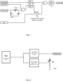
FIG. 1 shows a schematic view of a logic circuit according to an embodiment of the present application. -
FIG. 2 shows a schematic view of a signal output circuit according to an embodiment of the present application. - In order to make the purpose, technical scheme and advantages of the present application clearer, the technical solutions of the embodiments of the present application will be described in more detail below with reference to the accompanying drawings. It is obvious that the embodiments to be described are only some rather than all of the embodiments of the present application.
- All other embodiments obtained by those skilled in the art based on the embodiments of the present application without creative efforts shall fall within the scope of the present application.
- According to an embodiment of the present application, the control method of driving active short circuit for electric vehicle includes the steps of: outputting, by the power distribution unit (PDU) controller, the active short circuit safety state enable signal and the PDU relay shut-off signal synchronously. The PDU relay shut-off signal output by the PDU controller is synchronously output to the motor controller.
- The control method for different working conditions is as follows.
- 1. In response to that the vehicle fails in the boost charging mode (in overvoltage state): outputting, by the PDU relay, the shut-off signal, so that the motor control system exits the boost charging mode; and after the motor control system exits the boost charging mode, outputting the active short circuit safety state enable signal so that the motor control system enters the active short circuit safety state.
- 2. In response to that the vehicle is under a normal working condition and in the boost charging mode: outputting, by the PDU controller, the PDU relay start signal; and synchronously outputting to the motor controller to lock the output of the active short circuit safety state.
- 3. In response to that the vehicle fails in the driving mode and the overvoltage state is generated: triggering the motor control system to enter the active short circuit safety state based on the functional safety management signal.
- 4. In response to that the vehicle is under the normal working condition and in the driving mode: in response to that it is determined that the motor control system needs to enter the active short circuit safety state based on the bus voltage of the motor controller, making the motor control system to enter the active short circuit safety state based on the active short circuit safety state enable signal.
- 5. In response to that the connection of the connector between the motor controller and the PDU controller is unreliable: in response to that it is determined that the motor control system needs to enter the active short circuit safety state based on the bus voltage of the motor controller and the current mode of the vehicle, making the motor control system enter the active short circuit safety state based on the active short circuit safety state enable signal.
- 6. In response to that the vehicle is in the trailer mode: in response to that it is determined that the motor control system needs to enter the active short circuit safety state based on the bus voltage of the motor controller, making the motor control system enter the active short circuit safety state based on the active short circuit safety state enable signal.
- As shown in
FIG. 1 , the logic circuit schematic view includes two circuits for executing the active short circuit installation state. In the first circuit, in response to that a function fault signal is issued, and after function fault signal passes through isolation units S1 and S2, the active short circuit safety state execution (ASC_LS_EM) signal is directly triggered; in the second circuit, the ASC_LS_EM signal is selected to be triggered through the logic tri-state gate IC1. Since the output results of the two circuits are consistent, the first logic OR gate is adopted to reduce the complexity of the circuit. - As shown in
FIG. 2 , the PDU management micro controller unit (MCU) of the PDU controller outputs the active short circuit safety state enable (PDU_ASC_EN) signal through the ASC enable signal control circuit, and outputs the PDU relay shut-off signal of the charging control relay CB1 through the PDU charging control relay interface circuit at the same time, thereby realizing the synchronous output of the PDU_ASC_EN signal and the PDU relay shut-off signal. - Combined with the logic circuit view shown in
FIG. 1 , the specific logic of the above working conditions is as follows:
Under the third working condition, in response to that a fault occurs in the driving mode and an overvoltage state is generated, the motor control system is triggered by the functional safety management (SAFE STATE) signal to enter the active short circuit safety state. Since the logic of the PDU_ASC_EN signal is consistent with the logic of the SAFE STATE signal, the second logic OR gate is adopted to reduce the circuit complexity. - Under the second working condition, the PDU controller outputs the PDU relay start signal with a logic high level, the logic high level is synchronously output to the motor controller, and the motor controller works normally. At this time, the PDU_ASC_EN signal and the SAFE STATE signal are not output, the logic tri-state gate IC1 is in the cut-off state, thereby locking the output of the active short circuit safety state.
- Under the first working condition, in response to that the vehicle fails in the boost charging mode, the PDU controller synchronously outputs the PDU_ASC_EN signal and the PDU relay shut-off signal. The PDU relay shut-off signal is a logic low level and is synchronously output to the motor controller to make the motor control system exit the boost charging mode. The PDU_ASC_EN signal lags behind the PDU relay shut-off signal through the delay circuit. After passing through the isolation unit S1, the logic tri-state gate is turned on, thereby triggering the ASC gating under the overvoltage in the boost charging mode, that is, triggering the ASC_LS_EM signal. This ensures that the motor control system will not enter the ASC state in the boost charging mode.
- As shown in
FIG. 1 , the delay circuit is the RC circuit, which acts as a filter and also provides delay for the signal. The RC circuit includes a resistance R1, a resistance R2 and a capacitor C1. Both ends of the R1 are connected between the PDU_ASC_EN signal and the second logic OR gate, the first end of the R2 is connected between the R1 and the the PDU_ASC_EN signal, the second end of the R2 is grounded, the first end of the C1 is connected between the R1 and the second logic OR gate, and the second end of the C1 is connected to the second end of the R2. - Under the fourth working condition and the sixth working condition, in response to that the vehicle is in the driving mode or the trailer mode and under normal working conditions, the PDU controller outputs the PDU relay shut-off signal, i.e., the logic low level and outputs synchronously to the motor controller, and determines whether the motor control system needs to enter the active short circuit safety state based on the bus voltage of the motor controller.
- Under the fifth working condition, in response to that the connection of the connector between the motor controller and the PDU controller is unreliable, the control port is configured as low level. Since the voltage threshold for entering the active short circuit safety state is different in different modes of the vehicle, whether the motor control system needs to enter the active short circuit safety state is controlled by the bus voltage of the motor controller and the current vehicle mode.
- Under the fourth working condition, the fifth working condition and the sixth working condition, whether the motor control system needs to enter the active short circuit safety state is determined based on the bus voltage of the motor controller. Specifically, in response to that the bus voltage of the motor controller exceeds the first threshold voltage in the driving mode, the motor control system is triggered to enter the active short circuit safety state; in response to that the bus voltage of the motor controller is higher than the second threshold voltage in the trailer mode, the motor control system is triggered to enter the active short circuit safety state.
- As shown in
FIG. 1 , VDC_S is the bus voltage of the motor controller. Under normal working conditions, the logic tri-state gate is closed and VDC_S cannot affect the ASC logic. Under trailer working conditions, after the low-voltage test is powered off, since the high-voltage test has power (in the vehicle-mounted drive motor control system, the low voltage refers to the electronic unit or circuit powered by the 12V or 24V battery on the vehicle, and the high voltage refers to the power battery, usually 380V-800V powered electronic modules and units. Since the two power supply systems cannot have a physical path, isolation units S1 and S2 realize high and low voltage connection through magnetic field coupling), in response to that VDC_S is higher than the threshold, ASC can be triggered, that is, high-speed trailers can trigger ASC to avoid power module failure in the trailer mode. - The present application also provides a control apparatus of driving active short circuit for electric vehicle, including:
- a PDU management unit configured to synchronously output an active short circuit safety state enable signal and a PDU relay shut-off signal;
- a motor control unit configured to make the motor control system exit the boost charging mode based on the PDU relay shut-off signal;
- an active short circuit safety state trigger unit configured to make the motor control system enter the active short circuit safety state based on the active short circuit safety state enable signal after the motor control system exits the boost charging mode;
- a signal delay unit configured to make the active short circuit safety state enable signal lag behind the transmission of the PDU relay shut-off signal, so that after the motor control system exits the boost charging mode, the motor control system enters the active short circuit safety state based on the active short circuit safety state enable signal;
- an active short circuit safety state locking unit configured to lock the output of the active short circuit safety state in response to that the PDU management unit outputs the PDU relay start signal;
- a functional safety management unit configured to issue a functional safety management signal in response to that a fault occurs in the driving mode of the vehicle; the active short circuit safety state trigger unit is also configured to trigger the motor control system to enter the active short circuit safety state based on the functional safety management signal output by the functional safety management unit; and
- a determination unit configured to determine whether the motor control system needs to enter the active short circuit safety state based on the bus voltage of the motor controller in response to that the vehicle is in the driving mode or the trailer mode under normal working conditions; the determination unit is also configured to determine whether the motor control system needs to enter the active short circuit safety state based on the bus voltage of the motor controller and the current vehicle mode in response to that the connection of the connector between the motor controller and the PDU controller is unreliable.
- The implementation process of the functions and effects of the above module unit can be found in the implementation process of the corresponding steps in the control method of driving active short circuit for electric vehicle in the above embodiment of the present application, which will not be repeated. The present application also provides an electric vehicle, including the control apparatus for driving active short circuit in the above embodiment.
- The above are only embodiments of the present application and are not intended to limit the present application in any form. Although the present application has been disclosed as embodiments above, they are not intended to limit the present application. For those skilled in the art, without deviating from the technical scheme of the present application, when the technical content disclosed above can be used to make some changes or modifications into equivalent embodiments of equivalent changes, any content that does not deviate from the technical scheme of the present application and any simple modification, equivalent changes and modifications made to the above embodiments according to the technical substance of the present application shall still fall within the scope of the present application.
Claims (12)
- A control method of driving an active short circuit for an electric vehicle, characterized by comprising:outputting, by a power distribution unit, PDU controller, an active short circuit safety state enable signal and a PDU relay shut-off signal synchronously;in response to that the vehicle fails in a boost charging mode, making a motor control system exit the boost charging mode through the PDU relay shut-off signal; andafter the motor control system exits the boost charging mode, making the motor control system enter an active short circuit safety state through the active short circuit safety state enable signal.
- The control method of driving the active short circuit for the electric vehicle according to claim 1, wherein the active short circuit safety state enable signal is transmitted lagged behind the PDU relay shut-off signal through a delay circuit.
- The control method of driving the active short circuit for the electric vehicle according to claim 1, whereinin response to that the vehicle is under a normal working condition and in the boost charging mode, the PDU controller is configured to output a PDU relay start signal and output synchronously to a motor controller, so as to lock an output of the active short circuit safety state; andin response to that the vehicle fails in a driving mode, the motor control system is triggered to enter the active short circuit safety state based on a functional safety management signal.
- The control method of driving the active short circuit for the electric vehicle according to claim 1, wherein in response to that the vehicle is under the normal working condition and in the driving mode, the control method further comprises:outputting the PDU relay shut-off signal output by the PDU controller to a motor controller synchronously; andin response to determining that the motor control system needs to enter the active short circuit safety state based on a bus voltage of the motor controller, making the motor control system enter the active short circuit safety state based on the active short circuit safety state enable signal.
- The control method of driving the active short circuit for the electric vehicle according to claim 1, wherein in response to that a connection of a connector between a motor controller and the PDU controller is unreliable, the control method further comprises:
in response to determining that the motor control system needs to enter the active short circuit safety state based on a bus voltage of the motor controller and a current mode of the vehicle, making the motor control system enter the active short circuit safety state based on the active short circuit safety state enable signal. - The control method of driving the active short circuit for the electric vehicle according to claim 1, wherein in response to that the vehicle is in a trailer mode, the control method further comprises:outputting the PDU relay shut-off signal output by the PDU controller to a motor controller synchronously; andin response to determining that the motor control system needs to enter the active short circuit safety state based on a bus voltage of the motor controller, making the motor control system enter the active short circuit safety state based on the active short circuit safety state enable signal.
- A control apparatus of driving an active short circuit for an electric vehicle, characterized by comprising:a power distribution unit, PDU management unit configured to synchronously output an active short circuit safety state enable signal and a PDU relay shut-off signal, wherein the PDU relay shut-off signal is synchronously output to a motor controller;a motor control unit configured to make a motor control system exit a boost charging mode based on the PDU relay shut-off signal; andan active short circuit safety state trigger unit configured to make the motor control system enter an active short circuit safety state based on the active short circuit safety state enable signal after the motor control system exits the boost charging mode.
- The control apparatus of driving the active short circuit for the electric vehicle according to claim 7, further comprising:
a signal delay unit configured to make the active short circuit safety state enable signal lag behind a transmission of the PDU relay shut-off signal, so that after the motor control system exits the boost charging mode, the motor control system is configured to enter the active short circuit safety state based on the active short circuit safety state enable signal. - The control apparatus of driving the active short circuit for the electric vehicle according to claim 7, further comprising:
an active short circuit safety state locking unit configured to lock an output of the active short circuit safety state in response to that the a PDU relay start signal is output by the PDU management unit. - The control apparatus of driving the active short circuit for the electric vehicle according to claim 7, further comprising:a functional safety management unit configured to send a functional safety management signal in response to that the vehicle fails in a driving mode;wherein the active short circuit safety state trigger unit is further configured to trigger the motor control system to enter the active short circuit safety state based on the functional safety management signal.
- The control apparatus of driving the active short circuit for the electric vehicle according to claim 7, further comprising:
a determination unit configured to determine whether the motor control system needs to enter the active short circuit safety state based on a bus voltage of the motor controller in response to that the vehicle is in the driving mode or a trailer mode and under a normal working condition. - The control apparatus of driving the active short circuit for the electric vehicle according to claim 11, wherein the determination unit is further configured to determine whether the motor control system needs to enter the active short circuit safety state based on the bus voltage of the motor controller and a current mode of the vehicle in response to that a connection of a connector between the motor controller and a PDU controller is unreliable.
Applications Claiming Priority (2)
| Application Number | Priority Date | Filing Date | Title |
|---|---|---|---|
| CN202210648061.3A CN115107521B (en) | 2022-06-08 | 2022-06-08 | A control method and device for active short circuit of electric vehicle drive |
| PCT/CN2022/114713 WO2023236362A1 (en) | 2022-06-08 | 2022-08-25 | Control method and apparatus for driving active short circuit for electric vehicle |
Publications (2)
| Publication Number | Publication Date |
|---|---|
| EP4527664A1 true EP4527664A1 (en) | 2025-03-26 |
| EP4527664A4 EP4527664A4 (en) | 2026-03-18 |
Family
ID=83327167
Family Applications (1)
| Application Number | Title | Priority Date | Filing Date |
|---|---|---|---|
| EP22945496.2A Pending EP4527664A4 (en) | 2022-06-08 | 2022-08-25 | CONTROL METHOD AND DEVICE FOR CONTROLLING AN ACTIVE SHORT CIRCUIT FOR AN ELECTRIC VEHICLE |
Country Status (4)
| Country | Link |
|---|---|
| EP (1) | EP4527664A4 (en) |
| JP (1) | JP2025518919A (en) |
| CN (1) | CN115107521B (en) |
| WO (1) | WO2023236362A1 (en) |
Family Cites Families (20)
| Publication number | Priority date | Publication date | Assignee | Title |
|---|---|---|---|---|
| JP5311233B2 (en) * | 2010-12-27 | 2013-10-09 | 株式会社デンソー | Motor control device and electric power steering device using the same |
| DE102014211853A1 (en) * | 2014-06-20 | 2015-12-24 | Robert Bosch Gmbh | Voltage converter and method for converting an electrical voltage |
| CN104935143B (en) * | 2015-03-18 | 2018-09-07 | 中国科学院电工研究所 | A starter generator |
| CN105514941A (en) * | 2015-12-31 | 2016-04-20 | 联合汽车电子有限公司 | Electric vehicle inverter protective device and method |
| DE102016010740A1 (en) * | 2016-09-03 | 2017-03-30 | Daimler Ag | Operate a drive train by short-term active short circuit |
| CN107976627A (en) * | 2016-10-21 | 2018-05-01 | 宝沃汽车(中国)有限公司 | Method for diagnosing faults, system and the vehicle of motor driven systems |
| US10840845B2 (en) * | 2017-03-22 | 2020-11-17 | Aisin Aw Co., Ltd. | Vehicle drive control device |
| CN109159669B (en) * | 2018-07-24 | 2021-08-06 | 中国第一汽车股份有限公司 | A protection system and method for an electric drive system |
| CN111347853B (en) * | 2018-12-21 | 2022-01-07 | 比亚迪股份有限公司 | Motor control circuit, charging and discharging method, heating method and vehicle |
| CN109606156A (en) * | 2018-12-28 | 2019-04-12 | 深圳电擎科技有限公司 | A new energy vehicle and its motor drive and battery charging device |
| CN110011278B (en) * | 2019-04-10 | 2021-09-03 | 广州小鹏汽车科技有限公司 | Motor short-circuit protection method and device |
| DE102019002781A1 (en) * | 2019-04-16 | 2019-11-14 | Daimler Ag | A method of storing electrical energy in a high voltage power module for a vehicle and high voltage power module for storing electrical energy |
| JP7259563B2 (en) * | 2019-06-05 | 2023-04-18 | 株式会社アイシン | Rotating electric machine control system |
| CN113060001B (en) * | 2019-12-31 | 2023-06-20 | 北京新能源汽车股份有限公司 | Motor controller software overvoltage fault processing method and device and electric automobile |
| US11167644B2 (en) * | 2020-01-31 | 2021-11-09 | Lear Corporation | Method and system for notification of an active short circuit condition in an electric motor of a hybrid electric vehicle |
| KR102797069B1 (en) * | 2020-06-05 | 2025-04-18 | 현대자동차주식회사 | Vehicle and method for controlling thereof |
| CN112468057B (en) * | 2020-10-10 | 2025-06-10 | 蔚来汽车科技(安徽)有限公司 | Motor control method and circuit for vehicle, motor driving system and vehicle |
| CN113415164A (en) * | 2021-05-24 | 2021-09-21 | 江铃汽车股份有限公司 | Rapid discharge method, system and medium for electric vehicle and electric vehicle |
| CN113296022B (en) * | 2021-05-31 | 2023-06-20 | 一巨自动化装备(上海)有限公司 | A Real-time Diagnosis Method of Motor Active Short Circuit State |
| CN114336854B (en) * | 2021-12-30 | 2024-03-22 | 臻驱科技(上海)有限公司 | Protection system and method for high-voltage direct-current charging of electric automobile |
-
2022
- 2022-06-08 CN CN202210648061.3A patent/CN115107521B/en active Active
- 2022-08-25 JP JP2024572426A patent/JP2025518919A/en active Pending
- 2022-08-25 EP EP22945496.2A patent/EP4527664A4/en active Pending
- 2022-08-25 WO PCT/CN2022/114713 patent/WO2023236362A1/en not_active Ceased
Also Published As
| Publication number | Publication date |
|---|---|
| CN115107521A (en) | 2022-09-27 |
| JP2025518919A (en) | 2025-06-19 |
| CN115107521B (en) | 2025-06-24 |
| WO2023236362A1 (en) | 2023-12-14 |
| EP4527664A4 (en) | 2026-03-18 |
Similar Documents
| Publication | Publication Date | Title |
|---|---|---|
| CN112319259B (en) | Control system and control method for alternating-current charging electronic lock of electric automobile | |
| CN107662499A (en) | Electric control method and system under whole pure electric vehicle failure | |
| CN104943558A (en) | Charge control system and control method of plug-in hybrid power bus | |
| WO2023130945A1 (en) | Fault processing apparatus for high-voltage system of electric vehicle, and electric vehicle | |
| CN102501771B (en) | Control method for high voltage electricity safety protection of passenger vehicle | |
| CN219706697U (en) | Battery management system, automobile power supply system and automobile | |
| US12104424B2 (en) | Logic intelligent control system of train door based on intelligent control units | |
| CN204712890U (en) | A kind of charge control system of plug-in hybrid passenger car | |
| CN109532497B (en) | High-voltage interlocking control and detection circuit of electric automobile | |
| CN105711423A (en) | High-voltage safety control system of electric vehicle | |
| EP4527664A1 (en) | Control method and apparatus for driving active short circuit for electric vehicle | |
| CN105882421B (en) | A kind of limping control system, method and the electric vehicle of electric vehicle | |
| CN114872648B (en) | An intelligent power distribution control method and system | |
| CN112018750A (en) | Vehicle-mounted dual-power supply system | |
| CN108762173A (en) | Fault diagnosis and response method and system for hybrid electric vehicle | |
| CN111994128A (en) | Grid-connected control method and system for auxiliary inverter of urban rail train | |
| EP4696538A1 (en) | Safe power supply control system and method for range-extended electric test vehicle | |
| WO2023124759A1 (en) | Power battery relay control method, apparatus and new energy automobile | |
| CN212540669U (en) | Power-on self-detection circuit, air compressor controller and hydrogen fuel cell system | |
| CN212695713U (en) | Vehicle-mounted dual-power supply system | |
| CN115610352A (en) | A pure electric cement mixer truck top-mounted power extraction control circuit and method | |
| CN114670639A (en) | Active short circuit control framework, control method and system for pure electric vehicle | |
| CN111731103A (en) | Whole-vehicle power-off control strategy of pure electric vehicle | |
| CN118288792A (en) | A high voltage interlock fault detection method, device and medium | |
| CN110932392A (en) | Intelligent control system and control method for contactor |
Legal Events
| Date | Code | Title | Description |
|---|---|---|---|
| STAA | Information on the status of an ep patent application or granted ep patent |
Free format text: STATUS: THE INTERNATIONAL PUBLICATION HAS BEEN MADE |
|
| PUAI | Public reference made under article 153(3) epc to a published international application that has entered the european phase |
Free format text: ORIGINAL CODE: 0009012 |
|
| STAA | Information on the status of an ep patent application or granted ep patent |
Free format text: STATUS: REQUEST FOR EXAMINATION WAS MADE |
|
| 17P | Request for examination filed |
Effective date: 20241216 |
|
| AK | Designated contracting states |
Kind code of ref document: A1 Designated state(s): AL AT BE BG CH CY CZ DE DK EE ES FI FR GB GR HR HU IE IS IT LI LT LU LV MC MK MT NL NO PL PT RO RS SE SI SK SM TR |
|
| DAV | Request for validation of the european patent (deleted) | ||
| DAX | Request for extension of the european patent (deleted) | ||
| A4 | Supplementary search report drawn up and despatched |
Effective date: 20260216 |
|
| RIC1 | Information provided on ipc code assigned before grant |
Ipc: B60L 3/00 20190101AFI20260210BHEP Ipc: B60L 50/60 20190101ALI20260210BHEP Ipc: G01R 31/34 20200101ALI20260210BHEP |